

Page 1
Owner’s Manual
Main features
5 Provides numerous vocal eects for the guitarist
5 HARMONY automatically adds harmony to your vocal, based on your guitar playing
5 VOCODER uses your voice to add expressive power to your guitar performance
5 ENHANCE improves the clarity of your sound
5 PITCH CORRECT corrects inaccuracies in pitch
5 Four independent general-purpose FX units provide 20 distinctive eect types such as DISTORTION
and RADIO, and there are also two independent REVERB/DELAY units, giving you a high degree of
exibility for making eect settings
5 Panel layout that provides high functionality and emphasizes live performance, with an easily
readable screen display and an independent [HARMONY] switch
5 Memory function lets you store and recall 99 setups in internal memory
5 By connecting a USB cable or MIDI cable, you can synchronize the unit with an external MIDI device
or a DAW on your computer, or switch sounds and control parameters
Owner’s Manual (this document)
Read this rst. It explains the basic things you need to know in order to use the VE-500. For detailed information
on how to operate the VE-500, please download and refer to “Parameter Guide” (PDF le).
PDF Manual (download from the Web)
5 Parameter Guide
This explains all of the parameters of the
VE-500.
Before using this unit, carefully read “USING THE UNIT SAFELY” and “IMPORTANT NOTES” (the leaet “USING THE
UNIT SAFELY” and the Owner’s Manual (p. 20)). After reading, keep the document(s) where it will be available for
immediate reference.
© 2018 Roland Corporation
To obtain the PDF manual
1. Enter the following URL on your
computer.
http://www.boss.info/manuals/
?
2. Choose “VE-500” as the product name.
Page 2

Contents
Getting Ready . . . . . . . . . . . . . . . . . . . . . . . 3
Connecting the Equipment . . . . . . . . . . 3
Connecting the Equipment . . . . . . . . . . 4
Top Panel . . . . . . . . . . . . . . . . . . . . . . . . . . 5
Screen Structure . . . . . . . . . . . . . . . . . . . 6
Operation of the [1]–[3] Knobs . . . . . . . 7
Switching Pages . . . . . . . . . . . . . . . . . . . . 7
Turning On/O the Power . . . . . . . . . . . 8
Tuning (Tuner) . . . . . . . . . . . . . . . . . . . . . 8
Playing . . . . . . . . . . . . . . . . . . . . . . . . . . . . . . 9
Mic Settings . . . . . . . . . . . . . . . . . . . . . . . 9
Adjusting the Mic Sensitivity . . . 9
Phantom Power Settings . . . . . . . 9
Patch Structure . . . . . . . . . . . . . . . . . . . . . 9
Switching Between Memory and
Manual Modes . . . . . . . . . . . . . . . . . . . . . 9
Switching Patches . . . . . . . . . . . . . . . . . . 10
Adding a Harmony Eect . . . . . . . . . . . . 10
About the Play Screen . . . . . . . . . . . . . . . 10
Editing a Patch . . . . . . . . . . . . . . . . . . . . . . . 11
Basic Operation . . . . . . . . . . . . . . . . . . . . 11
Changing the Eect Connections 12
Changing the CTL & ASSIGN
Settings . . . . . . . . . . . . . . . . . . . . . . 13
Matching the Harmony to the
Key of the Song . . . . . . . . . . . . . . . 14
Saving a Patch (Write) . . . . . . . . . . . . . . . 15
Exchanging Patches . . . . . . . . . . . 15
Initializing a Patch . . . . . . . . . . . . . 15
System Settings (MENU) . . . . . . . . . . . . . 16
Basic Operation . . . . . . . . . . . . . . . . . . . . 16
Adjusting the Display Contrast . . . . . . . 17
Enabling/Disabling the Auto-O
Function . . . . . . . . . . . . . . . . . . . . . . . . . . 17
Returning to the Factory Settings
(Factory Reset) . . . . . . . . . . . . . . . . . . . . . 17
Synchronizing with a DAW or
External MIDI Device
Installing the USB Driver . . . . . . . . . . . . . 18
Installing the Dedicated Software . . . . 18
. . . . . . . . . . . . . . . . 18
Appendix . . . . . . . . . . . . . . . . . . . . . . . . . . . . 19
Error Messages . . . . . . . . . . . . . . . . . . . . . 19
Attaching the Rubber Feet . . . . . . . . . . . 19
Main Specications . . . . . . . . . . . . . . . . . 19
USING THE UNIT SAFELY . . . . . . . . . . . . . 20
IMPORTANT NOTES . . . . . . . . . . . . . . . . . . 20
* To prevent malfunction and equipment failure, always turn down the volume, and turn o all the units before
making any connections.
* The power to this unit will be turned o automatically after a predetermined amount of time has passed since it
was last used for playing music, or its buttons or controls were operated (Auto O function).If you do not want
the power to be turned o automatically, disengage the Auto O function (“Enabling/Disabling the Auto-O
Function” (p. 17)).
5 Any settings that you are in the process of editing will be lost when the power is turned o. If you have any
settings that you want to keep, you should save them beforehand.
5 To restore power, turn the power on again (p. 8).
2
Page 3
Getting Ready
1: GND 2: HOT
3: COLD
3: COLD
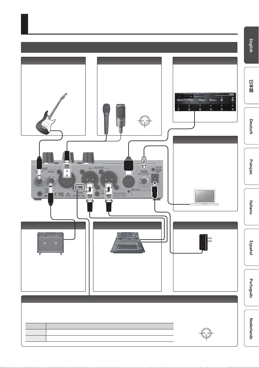
Connecting the Equipment
INST INPUT jack MIC IN connector
Connect your electric guitar or
other instrument here.
HARMONY or VOCODER eects
are applied to your vocal
according to your guitar playing.
Connect your mic here. If you
connect a condenser mic, turn
phantom power on as described
in "Phantom Power Settings"
(p. 9). The VE-500 is equipped
with a balanced (XLR) connector.
MIC IN connector
pin conguration
OUTPUT L, R connectorsINST THRU jack
3: COLD
MIDI IN connector
Connect an external MIDI device
here. The VE-500 can receive
program change messages, and
synchronize its tempo with a
MIDI device.
1: GND2: HOT
O (MICRO USB) port
Use a micro USB cable to connect
your computer here. This allows
MIDI and audio signals to be
exchanged.
* Do not use a micro USB cable that
is designed only for charging a
device. Charge-only cables cannot
transmit data.
DC IN jack
Connect your guitar amp or eect
unit here.
* The signal that enters the INST
INPUT jack is output from here.
Connect these connectors to your
PA mixer, etc. These connectors
output the signal processed by the
eects. The VE-500 is equipped with
balanced (XLR) connectors.
* The sound of the guitar is not output.
Connect the AC adaptor here.
* Use only the included AC
adaptor (PSA-S series), and
make sure that the AC outlet
is the correct voltage for the
adaptor.
[GND LIFT] switch
In some cases, you might hear “ground loop hum” (a buzz or hum) when the VE-500 is connected to an external device.
If this occurs, changing the setting of the [GND LIFT] switch might lessen the problem. Normally you'll leave this switch
in the NOR (NORMAL) position.
Switch Explanation
NOR Pin 1 of the OUTPUT jacks is connected to the VE-500’s GND.
LIFT Pin 1 of the OUTPUT jacks is disconnected from the VE-500’s GND.
OUTPUT connector pin
conguration
1: GND 2: HOT
3
Page 4
Getting Ready
1: GND2: HOT
1: GND 2: HOT
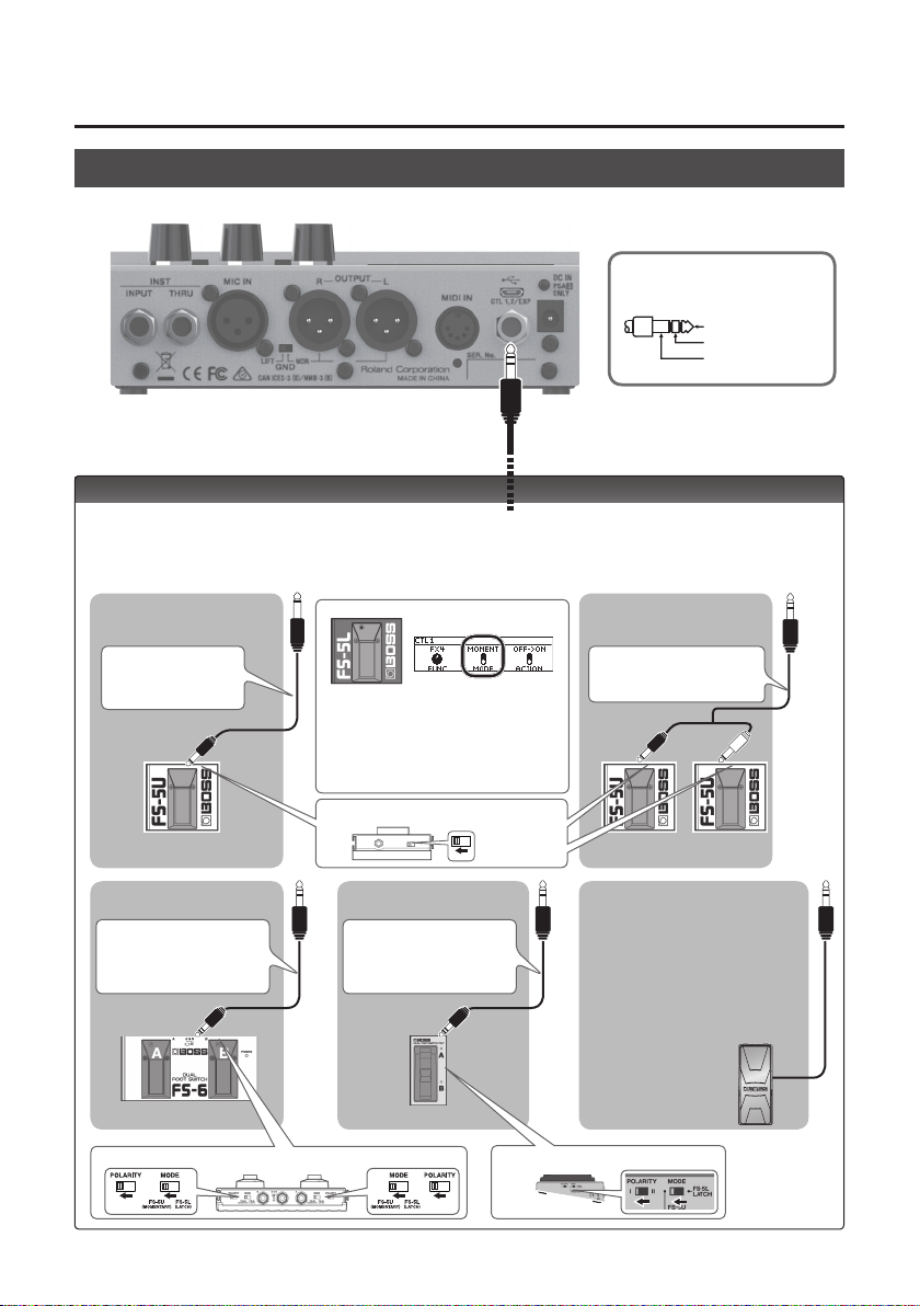
Connecting the Equipment
CTL 1, 2 / EXP jack pin
conguration
TIP: HOT
RING: COLD
SLEEVE: GND
CTL 1, 2/EXP jacks
You can control various parameters by connecting a footswitch (FS-5U, FS-5L, FS-6, FS-7: sold separately)
or an expression pedal (such as the FV-500H, FV-500L, EV-30, Roland EV-5: sold separately) to the CTL 1,
2/EXP jack (p. 13
When Connecting an FS-5U
(or FS-5L)
)
When Connecting Two FS-5Us
(or FS-5Ls)
1/4” phone type
,
1/4” phone type
Stereo 1/4” phone type
,
Stereo 1/4” phone type
CTL 2 CTL 1
4
Stereo 1/4” phone type
,
1/4” phone type x 2
When connecting an FS-5L, set MODE of
CTL IN1 / CTL IN2 to “MOMENT” (p. 13).
POLARITY switch
CTL 1 CTL 2 CTL 1
When Connecting an FS-7When Connecting an FS-6
Stereo 1/4” phone type
,
Stereo 1/4” phone
type
When connecting expression pedal
* Use only the specied
expression pedal (FV-500H,
F-500L, EV-30, Roland EV-5;
sold separately). By connecting
any other expression pedals,
you risk causing malfunction
and/or damage to the unit.
EXP
MODE/POLARITY switch
MODE/POLARITY switch
Page 5
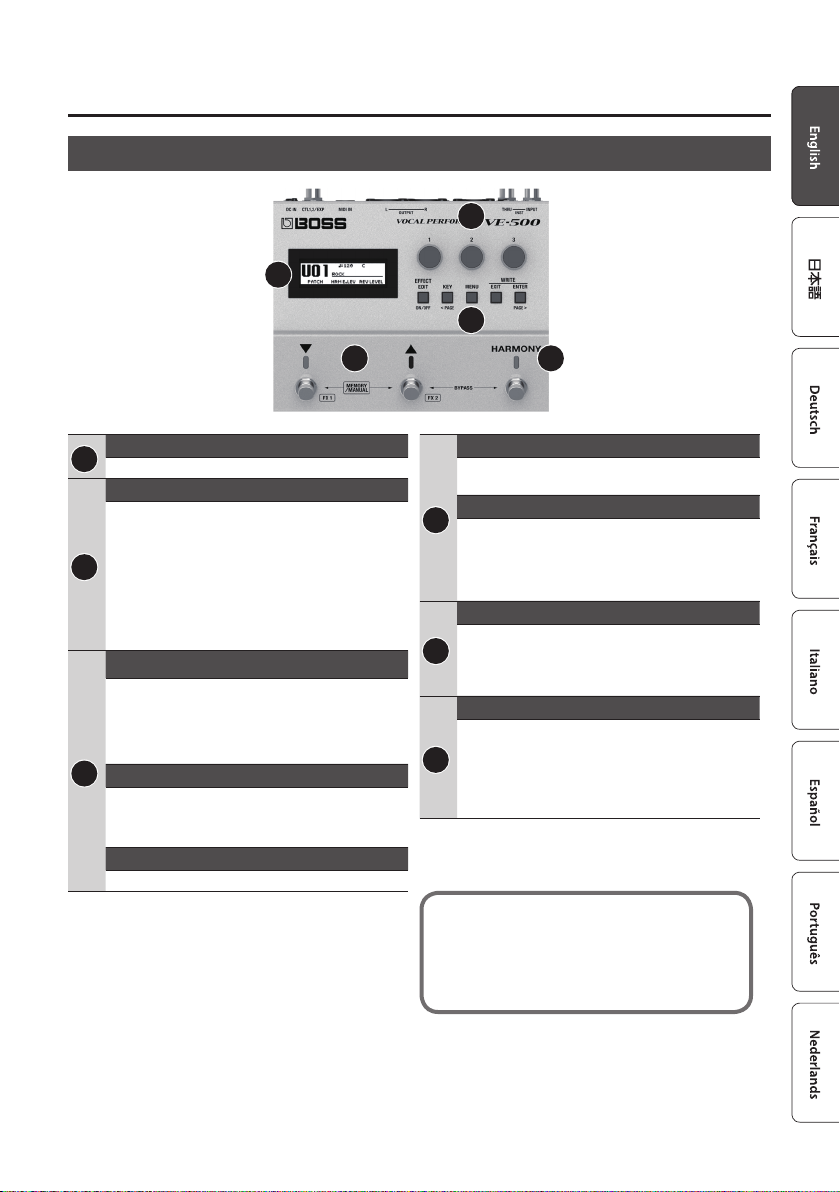
Top Panel
Getting Ready
2
1
3
4 5
Display
1
This shows various information for the VE-500.
[1]–[3] knob
Select and edit the parameter values shown in the
display.
* Refer to “Operation of the [1]–[3] Knobs” (p. 7)
2
* If the lock function is on, the [1]–[3] knobs are
disabled in the play screen (p. 10) to prevent
unintended operation. For more about the lock
function, refer to “Parameter Guide” (PDF).
[EFFECT EDIT] ( [ON/OFF] ) button
Makes patch settings. When editing, this button
turns on/o the selected eect.
3
[KEY]([< PAGE]) button
Species the key of the harmony.
5 In screens that show page tabs, use this as the
[< PAGE] button to switch pages.
[MENU] button
Lets you make system settings.
[EXIT] button
Cancels an operation or returns to the previous
screen.
[ENTER] ( [PAGE >] ) button
3
Press this to conrm an operation.
5 In screens that show page tabs, use this as the
[PAGE >] button to switch pages.
5 In the play screen, use this to switch the display.
[?] [=] switch
In memory mode, use these switches to select
4
patches. In manual mode, use these switches to
operate the assigned function (with the factory
settings, these turn FX1 and FX2 on/o).
[HARMONY] switch
Turns harmony on/o.
5 Press the [=] and [HARMONY] switches
5
simultaneously to bypass the eect.
5 Long-press the [=] and [HARMONY] switches
simultaneously to access the tuner screen.
The function of each switch can be freely assigned
in “CTL & ASSIGN SETTING” (p. 13). The color of
the indicator changes depending on the specied
function.
5
Page 6
Getting Ready
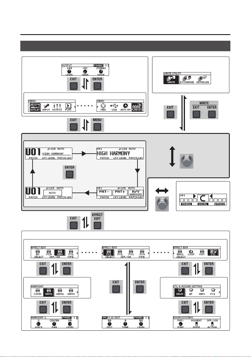
Screen Structure
MENU screen (p. 16)
Play screen (p. 10)
Use the [< PAGE]
[PAGE >] buttons to
change pages
Use the [1]–[3] knobs to
move the cursor
Use [ENTER] button to switch pages
WRITE UTILITY screen (p. 14)System settings (p. 16)
Use the [1]–[3] knobs to move the cursor
Memory mode
Press [?] + [=]
simultaneously
Manual mode
Tuner screen (p. 8)
[=] + [HARMONY] Hold for two seconds
Patch edit (p. 11)
Eect select screen (p. 11)
6
Use the [1]–[3] knobs to move the cursor
Use the [1]–[3] knobs
to move the cursor
Use the [< PAGE]
[PAGE >] buttons to
change pages
Use the [1]–[3] knobs
to move the cursor
CTL & ASSIGN screen (p. 13)HARMONY / VOCODER Screen (p. 11)
Use the [< PAGE]
[PAGE >] buttons to
change pages
Page 7

Operation of the [1]–[3] Knobs
5 In the play screen (p. 10), the [1]–[3] knobs
correspond to the functions that are assigned
by “System settings” -> “KNOB” (p. 16).
5 In the eect select screen (p. 11), the [1]–[3]
knobs have the following functions.
[1] knob [2] knob [3] knob
Move cursor Turn eect on/o Select eect type
Getting Ready
5 In the CTL & ASSIGN screen (p. 13), WRITE
UTILITY screen (p. 15), and MENU screen
(p. 16), you can move the cursor and select an
icon by operating any knob.
5 In screens where knob or switch icons are
shown, the [1]–[3] knobs correspond to those
icons.
OFF#ON
Switching Pages
5 When page tabs are displayed on the screen, you can switch pages by pressing the [< PAGE] [PAGE >]
buttons.
7
Page 8

Getting Ready
Turning On/O the Power
The DC IN jack also functions as the power switch. The power turns on when you insert the AC adaptor’s
plug into the DC IN jack, and turns o when you disconnect it.
* Before turning the unit on/o, always be sure to turn the volume down. Even with the volume turned down, you might hear
some sound when switching the unit on/o. However, this is normal and does not indicate a malfunction.
* Before you make connections, make sure that the input gain or volume of your mixer, recorder or amplier is turned down.
To turn the power on
Power-on in the following order: this unit (plug in the AC adaptor) 0 connected devices 0 amp.
To turn the power o
Power-o in the following order: amp 0 connected devices 0 this unit (unplug the AC adaptor).
Tuning (Tuner)
1. Simultaneously long-press (two
seconds or longer) the [=] switch and
[HARMONY] switch.
Specifying the reference pitch
Turn knob [1] to change the tuner's reference
pitch.
* Changing the tuner’s reference pitch also changes
the reference pitch for the harmony.
PITCH
435–445 Hz (default: 440 Hz)
Tuner Source
Turn knob [2] to select the input signal that is
The tuner screen appears.
detected by the tuner.
SOURCE Explanation
MIC Tune the mic
INST Tune the guitar
INST&M Tune both guitar and mic
2. Play your guitar or input your voice, and
tune your instrument. Tune so that only
the indicator in the center of the screen
is lit.
3. When you nish tuning, once again
long-press the [=] switch and
[HARMONY] switch simultaneously.
8
Output settings
Turn knob [3] to specify how the vocal sound is
output while you’re using the tuner.
VOCAL OUT Explanation
BYPASS Output with the eects o
DRY Output with ENHANCE applied
LEAD
MUTE Output is muted
Output with ENHANCE and PITCH
CORRECT applied
Page 9

Playing
Mic Settings
Adjusting the Mic Sensitivity
1. Press the [MENU] button.
2. Use the [1] knob to select “INPUT,” and
then press the [ENTER] button.
3. Use knob [1] to adjust the sensitivity of
the mic.
Triangular mark
Adjust the mic sensitivity appropriately while
watching the level meter in the screen.
* The appropriate sensitivity is when the loudest
input sound reaches the approximate position of
the triangular mark.
MIC SENS
0–200 (default: 100)
Phantom Power Settings
4. If you’re using a condenser mic, use
knob [3] to turn “PHANTOM” on.
Patch Structure
A combination of VE-500 eects and settings for
those eects is called a “patch.”
You can edit the settings of a patch and store it as
a “user patch.”
Preset patch User patch
Patch P50
Patch P03
Patch P02
Patch P01
HARMONY (VOCODER)
ENHANCE
PITCH CORRECT
FX1 / FX2 / FX3 / FX4
REVERB1/ REVERB2
CTL / MASTER / LOOP
Patch U99
Patch U03
Patch U02
Patch U01
HARMONY (VOCODER)
ENHANCE
PITCH CORRECT
FX1 / FX2 / FX3 / FX4
REVERB1/ REVERB2
CTL / MASTER / LOOP
Switching Between Memory and Manual Modes
Memory mode
In this mode you can recall and use patches that
are saved in the VE-500’s memory. Use the [?]
and [=] switches to select a patch.
Manual mode
In this mode you can operate the functions that
are assigned to the [?] and [=] switches.
1. Press the [?] switch and [=] switch
simultaneously.
PHANTOM Explanation
OFF Phantom power o
ON Phantom power on
5. Press the [EXIT] button a number of
times to return to the play screen.
Memory mode Manual mode
Each time you press these, you alternate
between memory mode and manual mode.
9
Page 10

Playing
Switching Patches
1. Switch to memory mode.
2. Use the [?] [=] switches to select a
patch.
Pressing [?] selects the previous patch number, and
pressing [=] selects the next patch number.
Patch down Patch up
You can turn knob [1] to select patches consecutively.
* You can’t switch patches unless you’re in the Play
screen (next item). Press the [EXIT] button to return
to the Play screen, and then switch patches.
About the Play Screen
The screen that appears after you turn on the
power is called the “Play screen.”
Press the [ENTER] button to switch the display.
Patch Number
[1] [2] [3]
Parameters edited by the three knobs
Patch Number
Patch Name
Parameters assigned to the switches
[?] [=]
Master BPM
Patch Name Key Setting
Master BPM
Key Setting
[HARMONY]
PHANTOM
power on
Knob
Lock on
PHANTOM
power on
Knob
Lock on
Adding a Harmony Eect
1. Press the [HARMONY] switch to make
the indicator light.
A harmony eect is applied.
Try singing while you play your guitar, and
notice the harmony eect.
* A function other than turning the harmony eect
on/o can also be assigned to the [HARMONY]
switch (p. 13).
10
Patch Number
Master BPM
Eect type
Key Setting
Page 11

Editing a Patch
Basic Operation
1. Recall the patch that you want to edit
(p. 10).
2. Press the [EFFECT EDIT] button.
The eect select screen appears.
3. Use knob [1] to select the eect that
you want to edit.
You can use the [EFFECT EDIT] ([ON/OFF])
button or knob [2] to turn on/o the eect
where the cursor is located (highlighted).
Eect Explanation
Improves the clarity of the sound.
Corrects inaccuracies in pitch. This is
available only when HRM (harmony)
is selected.
HRM: Adds harmony to your vocal.
VOC: A vocoder eect.
These let you select a variety of
eect types. You can also choose the
–
same eect for FX1–FX4.
These let you select reverb or delay.
Overdub-record additional sound,
and play it back as a loop.
Adjust the tonal character of
patches, and make other settings.
Refer to “Changing the CTL/ASSIGN
Settings” (p. 13).
MEMO
For FX1–4, and HRM (VOC), you can use knob
[3] to choose the eect type.
An eect that is on is shown by an icon. An eect that
is o is shown as "OFF."
For details on the parameter, refer to the
“Parameter Guide” (PDF le).
4. Press the [ENTER] button to access the
edit screen.
MEMO
In the edit screen, press the [ON/OFF] button
to turn the eect on/o. This lets you hear
what the eect does.
11
Page 12

Editing a Patch
In screens where page tabs are displayed,
use the [< PAGE] [PAGE >] buttons to move
between editing screen pages.
5. Use knobs [1]–[3] to specify the value of
each parameter shown in the screen.
6. Press the [EXIT] button a number of
times to return to the play screen.
Changing the Eect Connections
1. In the eect select screen, choose “MST.”
2. Use “FX STRUCTURE” to change the
order in which FX1–FX4 are connected.
3. Use “REVERB STRUCTURE” to change
the order in which REV1 and REV2 are
connected.
The eect connection changes.
FX STRUCTURE
STRUCTURE1: SERIES
LEAD
HARMONY1
HARMONY2
HARMONY3
STRUCTURE2: PARA+SER
LEAD
HARMONY1
HARMONY2
HARMONY3
STRUCTURE3: 2PARALLEL
LEAD
HARMONY1
HARMONY2
HARMONY3
STRUCTURE4: 4PARALLEL
LEAD
HARMONY1
FX1
FX2
FX1 FX2
FX3 FX4
FX1
FX2
Multi-FX
Multi-FX
FX3 FX4
Multi-FX
Multi-FX
FX OUT1FX1 FX2 FX3 FX4
FX OUT1
FX OUT1
FX OUT2
FX OUT1
FX OUT2
12
HARMONY2
HARMONY3
Output Explanation
LEAD
HARMONY1 Output the harmony sound
HARMONY2 Output the harmony sound
HARMONY3 Output the harmony sound
FX3
FX4
Output the sound with ENHANCE and
PITCH CORRECT applied
FX OUT3
FX OUT4
Page 13

Editing a Patch
REVERB STRUCTURE
STRUCTURE1: SERIES
FX OUT1
FX OUT2
FX OUT3
FX OUT4
STRUCTURE2: PARALLEL
FX OUT1
FX OUT2
FX OUT3
FX OUT4
STRUCTURE3: SEPARATE
FX OUT1
FX OUT2
FX OUT3
FX OUT4
REV/DLY1
REV/DLY2
REV/DLY1
REV/DLY2
REV/DLY1
REV/DLY2
Reverb
Reverb
Reverb
FX OUT
FX OUT
FX OUT
Changing the CTL & ASSIGN Settings
You can operate a variety of parameters by
making CTL and ASSIGN settings for each patch.
1. In the eect select screen, use knobs
[1]–[3] to select “CTL,” and then press
the [ENTER] button.
The CTL & ASSIGN screen appears.
2. Use knobs [1]–[3] to select the
controller that you want to edit.
An icon indicates controllers that are turned
on. Controllers that are o are indicated by
“OFF.”
Controller
Explanation
Species the parameter that is
controlled by the [?] and [=]
–
switches when in Memory mode.
* This works only in Memory mode.
Species the parameter that is
controlled by the [?] ([FX1]) and
[=] ([FX2]) switches when in Manual
–
mode.
* This works only in Manual mode.
Species the parameter that is
controlled by the [HARMONY]
switch.
Species the parameter that is
controlled by an expression pedal
(EXP) connected to the CTL 1, 2/
EXP jack.
Species the parameter that is
–
controlled by a footswitch (CTL 1–2)
connected to the CTL 1, 2/EXP jack.
Species the parameter that is
controlled by pressing the [?] and
[=] switches simultaneously.
Species the parameter that
is controlled by pressing the
[=] and [HARMONY] switches
simultaneously.
13
Page 14

Editing a Patch
Controller
Explanation
ASSIGN allows you to make more
detailed settings.For example,
you can use ASSIGN if you want
to simultaneously control another
–
parameter in addition to operating
the parameter of the [?] switch.
You can specify eight dierent
settings for each patch.
Make common settings for “ASSIGN.”
3. Press the [ENTER] button to move to the
edit screen.
In screens that show page tabs, use the [<
PAGE] [PAGE >] buttons to switch between edit
screen pages.
4. Use knobs [1]–[3] to edit the parameter
values in the screen.
5. Press the [EXIT] button a number of
times to return to the play screen.
Matching the Harmony to the Key of the Song
1. Press the [KEY] button.
2. Use knob [1] to specify the “AUTO”
setting.
If Auto is set to “FULL” or “HYBRID,” the key
is specied automatically according to the
chords and the chord progression that you
play on the connected guitar.
AUTO Explanation
FULL
HYBRID
OFF
* Try the FULL setting, and if you don’t get the
harmony that you expect, use the HYBRID setting. If
you’re not using a guitar, turn this OFF and specify
the key.
3. Use knob [2] to specify the “KEY.”
* As shown in the illustration below, specify the key of
the song that you’re singing.
(Example) If you’re singing a song in A minor, set the
key to the relative key of “C.”
Harmony is added according to the
chords and the chord progression that
you play on your guitar.
Harmony is added according to the
“KEY” setting and the chords that you
play on your guitar.
Harmony is added according to the
“KEY” setting.
14
4. Press the [EXIT] button a number of
times to return to the play screen.
You can also add harmony according to note
data that’s input via the MIDI IN connector.
Page 15

Editing a Patch
Saving a Patch (Write)
If you want to save the patch that you created,
execute the Write operation.
* You can use dedicated software to save,
exchange, initialize, or back up patches (p. 18).
NOTE
5 If you do not save the patch, the edited
settings will be lost when you turn o the
power or switch to another patch.
5 When you save, the patch that had been in the
save-destination is overwritten.
1. Press the [EXIT] button and [ENTER]
button simultaneously.
The WRITE UTILITY screen appears.
2. Select “WRITE” and then press the
[ENTER] button.
3. Choose the patch write destination
(U01–U99) with the [1] knob, and press
the [ENTER] button.
Here you can edit the name.
Controller Operation
[1] knob Changes the character
[2] knob Moves the cursor
[3] knob Selects the type of characters
[EFFECT EDIT]
button
[MENU] button
4. To save the patch, press the [ENTER]
button.
Delete the character at the cursor
location
Insert a space at the cursor
location
* If you decide to cancel, press the [EXIT] button.
Once the patch has been saved, you
arereturned to the Play screen.
Exchanging Patches
Here’s how to exchange the currently selected
patch with a patch that you specify.
1. In the WRITE UTILITY screen, select
“EXCHANGE” and press the [ENTER]
button.
2. Choose the exchange-destination patch
with the [1] knob.
3. To exchange the patches, press the
[ENTER] button.
* If you decide to cancel, press the [EXIT] button.
Once the patches has been exchanged, you are
returned to the Play screen.
Initializing a Patch
Here’s how to return the selected patch to the
default values.
1. In the WRITE UTILITY screen, select
“INITIALIZE” and press the [ENTER]
button.
2. Choose the initialize-destination patch
with the [1] knob.
3. To initialize the patch, press the [ENTER]
button.
* If you decide to cancel, press the [EXIT] button.
Once the patch has been initialized, you are
returned to the Play screen.
15
Page 16

System Settings (MENU)
Settings that are shared by the entire VE-500 are
called “system settings.”
For details on the parameter, refer to the
“Parameter Guide” (PDF le).
Basic Operation
1. Press the [MENU] button.
The MENU screen appears.
2. Choose the item that you want to edit.
Item Explanation
Adjust the contrast of the display.
Make input-related settings.
Make output-related settings.
Make settings for the option functions
during performance.
Item Explanation
Refer to “Restoring the Factory Default
Settings (Factory Reset)” (p. 17).
3. Press the [ENTER] button to enter the
edit screen.
When page tabs are displayed on the screen,
you can switch pages by pressing the [<PAGE]
[PAGE>] buttons.
4. Use the [1]–[3] knobs to edit the value
of the parameters shown in the screen.
5. Press the [EXIT] button a number of
times to return to the play screen.
* There is no Write function for the system settings.
When you specify a parameter setting, the change is
saved and applied automatically.
16
Specify the functions of knobs [1]–[3]
operated in the play screen.
External pedals, and other settings will
have independent settings for each
patch or will share the same settings for
all patches.
This is the tuner screen.
Make MIDI-related settings.
Make USB-related settings.
Refer to “Enabling/Disabling the AutoO Function” (p. 17).
Page 17

System Settings (MENU)
Adjusting the Display Contrast
You can adjust the brightness of the display.
1. In the MENU screen, select “DISPLAY”
and press the [ENTER] button.
2. Adjust the contrast with the [1] knob.
Enabling/Disabling the Auto-O Function
If you set the auto-o function to “On,” the power
will turn o automatically when 10 hours have
passed since you last played or operated the unit.
The display will show a message approximately 15
minutes before the power turns o.
* With the factory settings, this is turned “on.” If you
don’t need the power to turn o automatically, turn
this “o.”
* If the power was turned o by the Auto O
function, disconnect and then reconnect the AC
adaptor to turn the power on again.
1. In the MENU screen, select “AUTO OFF”
and press the [ENTER] button.
2. Set the On (AUTO OFF) or OFF with the
[1] knob.
Returning to the Factory Settings (Factory Reset)
Restoring the VE-500’s settings to their original
factory default settings is referred to as “Factory
Reset.”
Not only can you return all of the settings to the
values in eect when the VE-500 was shipped
from the factory, you can also specify the items to
be reset.
* When you execute “Factory Reset,” the settings you
made will be lost. Save the data you need to your
computer using the dedicated software.
1. In the MENU screen, choose “F. RST” and
press the [ENTER] button.
2. Choose the type of settings to be
restored to the factory default settings
with knobs [1] and [3].
Parameter Value Explanation
[1] knob
FROM
[3] knob
TO
SYSTEM
U01–U99
SYSTEM
U01–U99
System parameter settings
Settings for Patch
Numbers U01–U50
System parameter settings
Settings for Patch
Numbers U01–U50
3. Press the [ENTER] button.
4. To execute the factory reset, use the
knob to select “OK,” and press the
[ENTER] button.
* If you decide not to execute the factory reset, select
“CANCEL” and press the [ENTER] button.
Once the Factory Reset is complete, you are
returned to the Play screen.
17
Page 18

Synchronizing with a DAW or External MIDI Device
By transmitting and receiving MIDI messages, the
VE-500 can synchronize with a computer or an external
MIDI device. For example, you can switch VE-500
patches from an external MIDI device or DAW, or match
the tempo.
If the VE-500 is connected via USB to a computer, you
can also use dedicated software to do the following.
5 Edit patch settings.
5 Rename patches.
5 Change the order of patches, or replace them.
5 Back up patches and internal settings, or restore the
backed-up settings.
5 View the “Parameter Guide” and “MIDI Implementation
Chart” (PDF).
Connection example
DAW
External MIDI device
MIDI messages that can be
transmitted and received
Patch change
Bank select (CC#0, #32) and program change
Synchronization data
Tempo clock (F8)
Patch data
System Exclusive messages
* Control change transmission and reception are
specied by the ASSIGN settings. In addition to
receiving control changes, the VE-500 can also
transmit them when you operate a switch or the
EXP pedal.
For details on the parameter, refer to
the “Parameter Guide” (PDF le).
Installing the USB Driver
You must install the USB driver before
connecting to a computer.
Please download the USB driver from the BOSS
website.
Install this special driver before making a USB
connection.
Download the USB driver from the BOSS website.
For details, refer to Readme.htm which is included
in the download.
&https://www.boss.info/support/
The program you need to use, and the steps you
need to take to install the USB driver will dier
depending on your computer setup, so please
carefully read and refer to the Readme.htm le
that comes with the download.
Installing the Dedicated Software
You can easily download dedicated software from
the BOSS website.
& https://www.boss.info/support/
For details on how to use the software, refer to the
Readme.htm le that comes with the download.
Other messages
Note (receiving only)
Control changes
18
Page 19

Appendix
Error Messages
Display Problem Action
SENDING BULK DATA
RECEIVING BULK DATA
MIDI OFFLINE
MIDI BUFFER FULL
USB CONNECTED
USB DISCONNECTED
KNOB IS LOCKED
MEMORY DAMAGED!
Attaching the Rubber Feet
Currently transmitting a MIDI bulk dump. -
Currently receiving a MIDI bulk dump. -
Communication from the connected device
has been interrupted. This message is also
displayed if the connected device is poweredo. This is not a malfunction.
An excessive amount of MIDI data was received
in a short time from an external MIDI device
connected to the MIDI IN connector, and the
VE-500 was unable to process it.
The USB cable is connected. -
Communication from the connected device
has been interrupted. This message is also
displayed if the connected device is poweredo. This is not a malfunction.
The buttons and knobs are locked. Turn o the lock function.
User memory is damaged.
You can attach the rubber feet (included) if necessary.
* When turning the unit over, be careful so as to protect the buttons and knobs from damage.
Also, handle the unit carefully; do not drop it.
* Attach the rubber feet correctly. If they are not attached correctly, they could deform or
malfunction.
Check whether the connection cable
might be disconnected or broken.
Reduce the amount of MIDI data that is
being sent to the VE-500.
Check whether the connection cable
might be disconnected or broken.
Execute the factory reset operation
(p. 17). If this does not solve the
problem, a malfunction might have
occurred. Consult the nearest Roland
service center.
Main Specications
BOSS VE-500: Vocal Performer
Power Supply AC Adaptor
Current Draw 310 mA (with phantom power) 210 mA (without phantom power)
Dimensions
Weight 860 g 1 lb 15 oz
Display Graphic LCD (132 x 32 dots, backlit LCD)
Accessories AC adaptor: PSA series, Owner’s manual, Leaet “USING THE UNIT SAFELY,” Rubber Feet x 4
Options
(sold separately)
* 0 dBu = 0.775 Vrms
* This document explains the specications of the product at the time that the document was issued. For the latest
information, refer to the Roland website.
170 (W) x 138 (D) x 62 (H) mm
6-3/4 (W) x 5-7/16 (D) x 2-1/2 (H) inches
Footswitch: FS-5U, FS-5L
Dual Footswitch: FS-6, FS-7
Expression Pedal: FV-500H, FV-500L, EV-30, Roland EV-5
19
Page 20

USING THE UNIT SAFELY
WARNING
Concerning the Auto O function
The power to this unit will be turned o
automatically after a predetermined amount of
time has passed since it was last used for playing
music, or its buttons or controls were operated
(Auto O function). If you do not want the
power to be turned o automatically, disengage the Auto
O function (p. 17).
Use only the supplied AC adaptor and the correct
voltage
Be sure to use only the AC adaptor supplied with
the unit. Also, make sure the line voltage at the
installation matches the input voltage specied
on the AC adaptor’s body. Other AC adaptors
may use a dierent polarity, or be designed for a dierent
voltage, so their use could result in damage, malfunction,
or electric shock.
IMPORTANT NOTES
Placement
• Depending on the material and
temperature of the surface on which
you place the unit, its rubber feet may
discolor or mar the surface.
Repairs and Data
• Before sending the unit away for repairs,
be sure to make a backup of the data
stored within it; or you may prefer to
write down the needed information.
Although we will do our utmost to
preserve the data stored in your unit
when we carry out repairs, in some
cases, such as when the memory section
is physically damaged, restoration of
the stored content may be impossible.
Roland assumes no liability concerning
the restoration of any stored content that
has been lost.
Additional Precautions
• Any data stored within the unit can be
lost as the result of equipment failure,
incorrect operation, etc. To protect
yourself against the irretrievable loss
of data, try to make a habit of creating
regular backups of the data you’ve
stored in the unit.
• Roland assumes no liability concerning
the restoration of any stored content
that has been lost.
• Never strike or apply strong pressure to
the display.
CAUTION
Keep small items out of the reach of children
To prevent accidental ingestion of
the parts listed below, always keep
them out of the reach of small
children.
• Accessories
Rubber Feet (p. 19)
• Use only the specied expression pedal.
By connecting any other expression
pedals, you risk causing malfunction
and/or damage to the unit.
• Do not use connection cables that
contain a built-in resistor.
CAUTION
Precautions concerning use of phantom power
supply
Always turn the phantom
power o when connecting any
device other than condenser
microphones that require
phantom power. You risk causing
damage if you mistakenly supply
phantom power to dynamic
microphones, audio playback
devices, or other devices that
don’t require such power. Be sure to check
the specications of any microphone you
intend to use by referring to the manual
that came with it.
(This instrument’s phantom power: 48 V
DC, 10 mA Max)
Licenses/Trademarks
• ASIO is a trademark and software of
Steinberg Media Technologies GmbH.
• This product contains eParts integrated
software platform of eSOL Co.,Ltd. eParts
is a trademark of eSOL Co., Ltd. in Japan.
• Roland and BOSS are either registered
trademarks or trademarks of Roland
Corporation in the United States and/or
other countries.
• Company names and product names
appearing in this document are
registered trademarks or trademarks of
their respective owners.
20
 Loading...