

Boss OD-200 Owner’s Manual
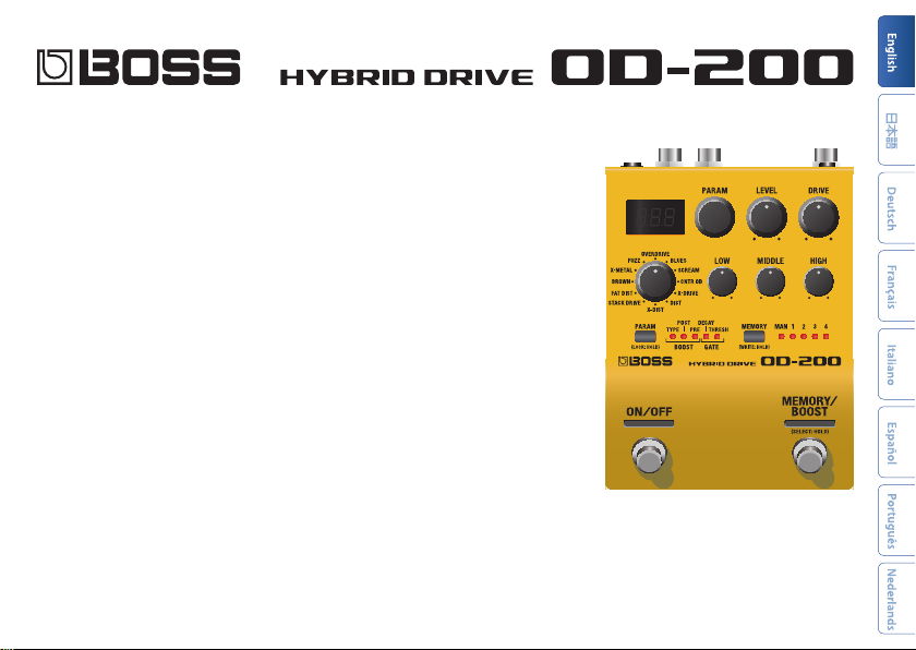
Owner’s Manual
Before using this unit, carefully read “USING THE UNIT SAFELY” and “IMPORTANT NOTES” (the leaet “USING THE UNIT SAFELY” and the Owner’s
Manual (p. 16)). After reading, keep the document(s) where it will be available for immediate reference.
© 2019 Roland Corporation
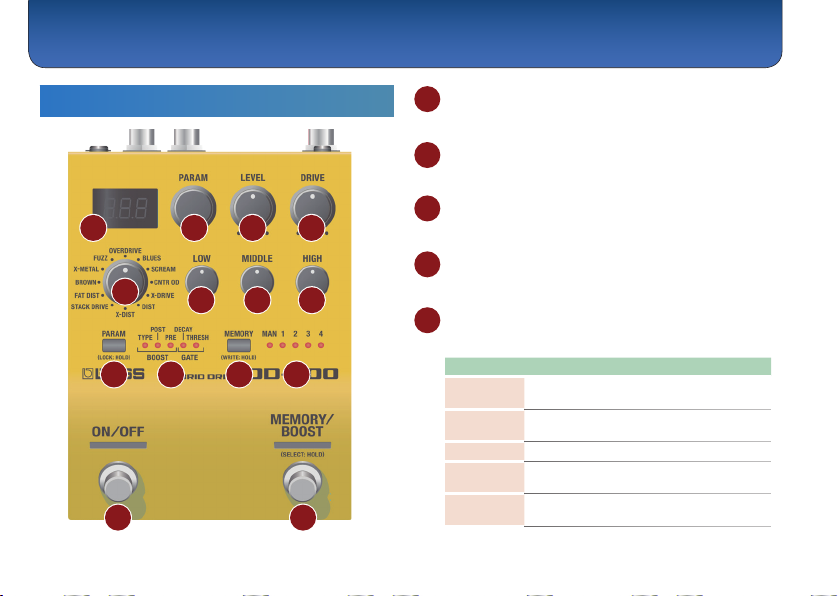
Panel Descriptions
Top Panel
1
9 10 11 12
13 14
2
1 Display
Shows the parameters and the values.
2 [PARAM] knob
Adjusts the parameter that’s selected by the [PARAM] button.
3 [LEVEL] knob
3 4
2
Adjusts the volume of the eect sound.
4 [DRIVE] knob
5
6
8
7
Adjusts the depth of distortion.
5 Mode knob
Selects the sound.
Mode Explanation
OVD
(OVERDRIVE)
BLS (BLUES)
SCR (SCREAM)
CNT (CNTR OD)
XDR (X-DRIVE)
Uses an asymmetrical overdrive circuit to
produce sweet, mild distortion.
Providing distortion that faithfully reproduces
the nuances of your picking.
Sound similar to the Ibanez TS-808.
An eect that models the sound of the KLON
CENTAUR.
Overdrive that uses MDP to provide ideal
distortion in each frequency region.
Panel Descriptions
Mode Explanation
DST (DIST)
XDS (X-DIST)
STK
(STACK DRIVE)
FAT (FAT DIST)
BRW (BROWN)
XMT (X-METAL)
FUZ (FUZZ)
This gives a basic, traditional distortion sound.
Distortion that uses MDP to provide ideal
distortion in each frequency region.
Produces the sound of a large stack amp.
Drive settings provide a diverse variety of
distortion.
Distortion that provides a thick distortion
sound.
Lead sound with a distinct edge.
Core sound that uses MDP to preserve the
sound's denition even with extreme gain.
Sound similar to an Electro-Harmonix Big
Mu π.
6 [LOW] knob
Adjusts the sound level of the low-frequency range.
7 [MIDDLE] knob
Adjusts the sound level of middle-frequency range.
8 [HIGH] knob
Adjusts the sound level of the high-frequency range.
9 [PARAM] button
Selects the parameter that’s adjusted by the [PARAM]
knob.
Parameter Explanation
BOOST TYPE
(BOOSTER TYPE)
MID: A booster with a distinctive
mid-range. A sound suitable for
soloing.
(CLEAN) : Raises the gain without
CLN
changing the guitar’s character.
(TREBLE) : A bright-sounding
TRB
booster.
(OVERDRIVE) : This models the
OVD
sound of the BOSS OD-1.
(BLUES) : This is a crunch sound of
BLS
the BOSS BD-2.
(SCREAM) : This models an Ibanez
SCR
TS-808.
(CNTR OD) : This models a KLON
CNT
CENTAUR.
(X-DRIVE) : This is an overdrive that
Xdr
uses MDP to obtain the distortion
that’s most appropriate in each pitch
range.
(DIST) : This models the sound of
DST
the BOSS DS-1.
3
Panel Descriptions
Parameter Explanation
BOOST TYPE
(BOOSTER TYPE)
BOOST PRE
(BOOSTER PRE GAIN)
BOOST POST
(BOOSTER POST GAIN)
GATE DECAY
GATE THRESH
(GATE THRESHOLD)
4
XDS (X-DIST) : This is a distortion that
uses MDP to obtain the distortion
that’s most appropriate in each pitch
range.
(STACK DRIVE) : This models the
STK
sound of the BOSS ST-2.
(FAT DIST) : A distortion sound with
FAT
thick distortion.
(METAL ZONE) : This models the
MZN
sound of the BOSS MT-2.
(METAL CORE) : This models the
MCR
sound of the BOSS ML-2.
(FUZZ) : This models an Electro-
FUZ
Harmonix Big Mu π.
Adjusts the gain of the booster.
Adjusts the volume when boost is on.
Adjusts the time until the gate closes.
With smaller values, the gate closes
faster.
Adjusts the volume at which the gate
applies.
With larger values, the gate applies at
a higher volume.
You can also select the parameter by pressing the
[PARAM] knob.
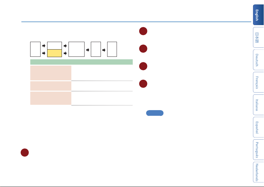
About the booster
As its main distortion, the OD-200 provides 12 dierent types of
sound.
The position of the booster connection and the operations of the
BOOSTER PRE GAIN, BOOSTER POST GAIN, and LOW/MIDDLE/HIGH
knobs will dier depending on the STRUCTURE parameter.
When STRUCTURE is SERIES
The booster is placed before the main distortion.
Booster
Guitar
&
Pre GAIN
Parameter Explanation
BOOST PRE
(BOOSTER PRE GAIN)
BOOST POST
(BOOSTER POST GAIN)
[LOW] [MIDDLE]
[HIGH] knobs
Main
Booster
&
distortion
&
Post GAIN
Gate&Amp
&
Adjusts the booster gain.
Increasing this value increases the
signal that is input to the main
distortion, making the distortion
stronger. The distortion of the booster
itself does not change.
Adjusts the volume when boost is on.
This let you raise (or lower) the
volume when using the booster to
increase the gain when transitioning
from backing to solo.
Adjust the tonal character of the main
distortion.
Panel Descriptions
When STRUCTURE is PARALLEL
The booster and main distortion are placed in parallel.
Main
[LOW]
[MIDDLE]
[HIGH]
Adjusts the booster gain.
Depending on the type, the sound
will distort.
Adjusts the volume of the booster.
Adjust the tonal character of the
main distortion and the booster as
a whole.
Gate
Amp
Booster
Guitar
distortion
Parameter Explanation
BOOST PRE
(BOOSTER PRE GAIN)
BOOST POST
(BOOSTER POST GAIN)
[LOW] [MIDDLE]
[HIGH] knobs
Preventing accidental operation (panel lock)
By long-pressing the [PARAM] button, you can switch
between enabling (unlocking) or disabling (locking)
operation of the knobs and buttons.
If you attempt an operation while the unit is locked, the
display indicates “LCK.”
10 BOOST/GATE indicator
Indicates the parameter that can be adjusted by the
[PARAM] knob.
11 [MEMORY] button
Switches or saves memories (MANUAL, 1–4) (p. 8).
12 MEMORY indicator
Indicates the currently selected memory.
13 [ON/OFF] switch
Turns the eect on/o.
14 [MEMORY/BOOST] switch
Switches memories (p. 8).
Long-press the [MEMORY/BOOST] switch to turn the
booster on/o.
MEMO
The function of the footswitch can be changed by
“MFC” (MEMORY SWITCH FUNCTION).
5
Panel Descriptions
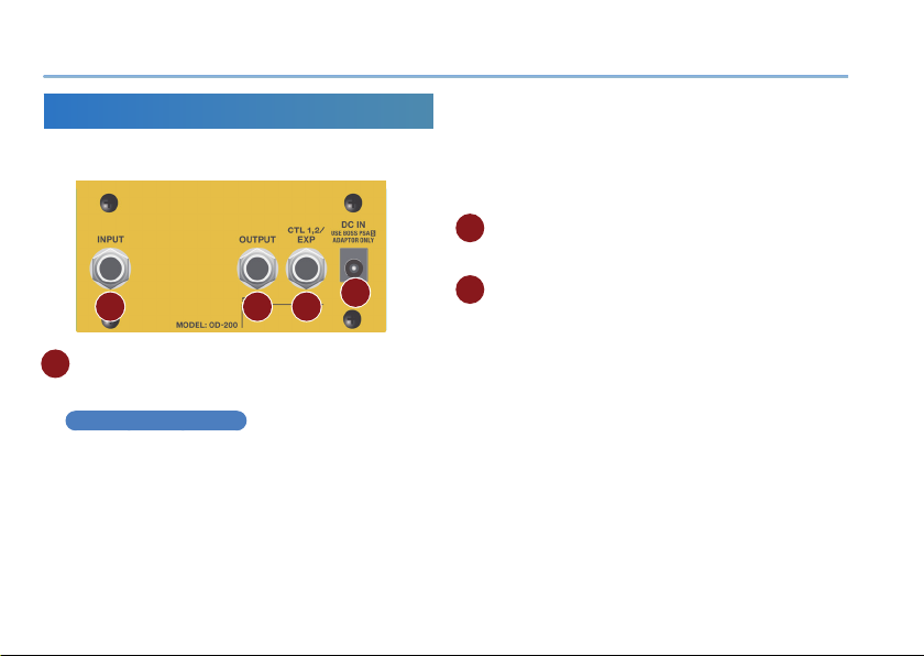
Rear Panel (Connecting Your Equipment)
* To prevent malfunction and equipment failure, always turn down the
volume, and turn o all the units before making any connections.
A B C
A
INPUT jack
Connect your guitar, bass, or eect unit here.
Turning On/O the Power
The INPUT jack also operates as the power switch. The
power turns on when you insert a plug into the INPUT
jack.
When powering up
Power-up equipment such as your guitar amp last.
6
D
When powering down
Power-down equipment such as your guitar amp rst.
* Before turning the unit on/o, always be sure to turn the volume
down. Even with the volume turned down, you might hear some
sound when switching the unit on/o. However, this is normal and
does not indicate a malfunction.
B OUTPUT jack
Connect this jack to your amp or eector.
C CTL 1, 2/EXP jack
Using the jack as CTL 1, 2
You can connect a footswitch (sold separately: FS-5U,
FS-6, FS-7) and use it to switch the booster ON/OFF or
switch memories (p. 9).
Using the jack as EXP
You can connect an expression pedal (sold separately:
EV-30, Roland EV-5, etc.) and use it to control the
amount of boost or the volume of the eect sound (p.
11).
* Use only the specied expression pedal. By connecting any other
expression pedals, you risk causing malfunction and/or damage
to the unit.
 Loading...