

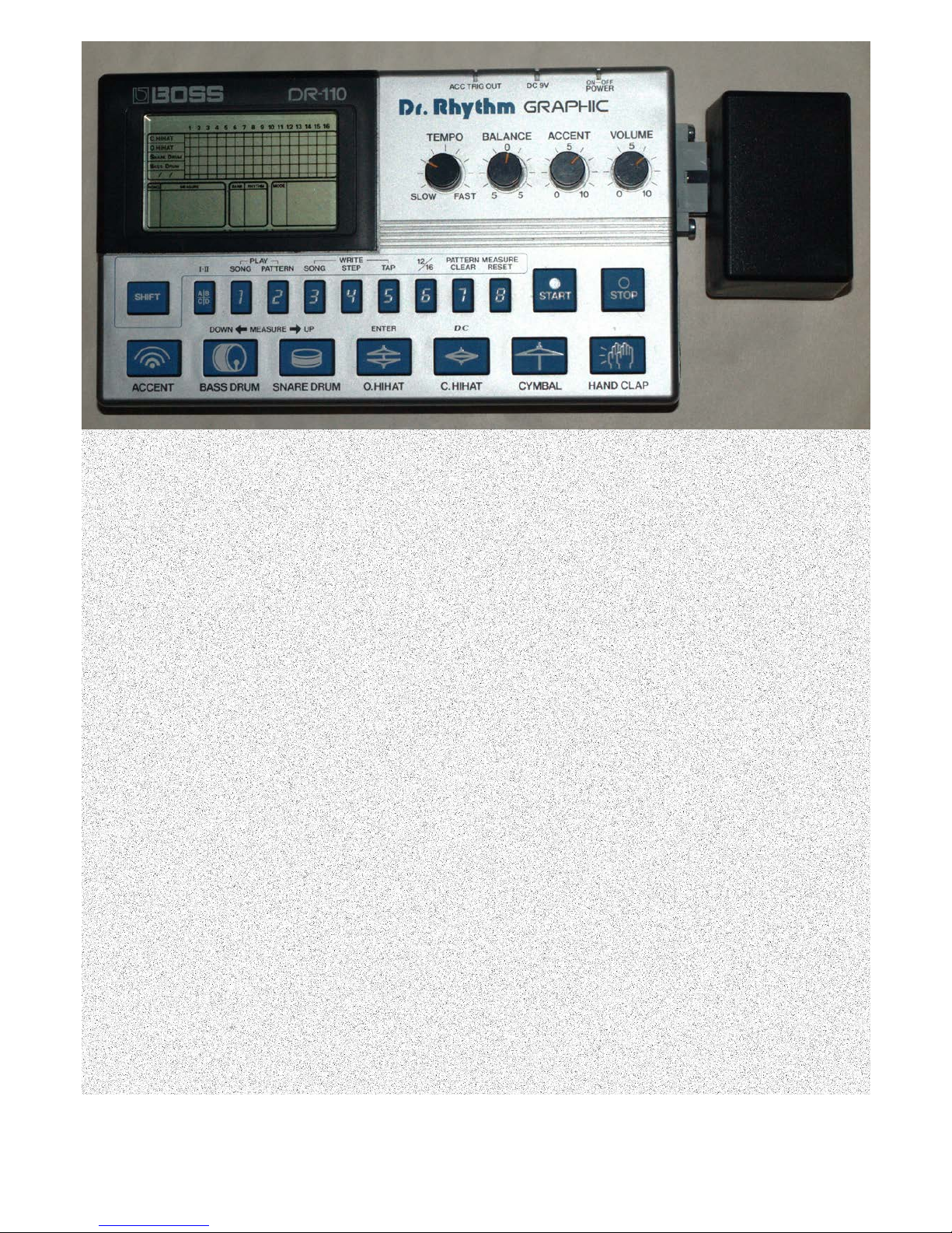
Boss DR-110 MIDI Interface Manual
1 V1.1
Assembly
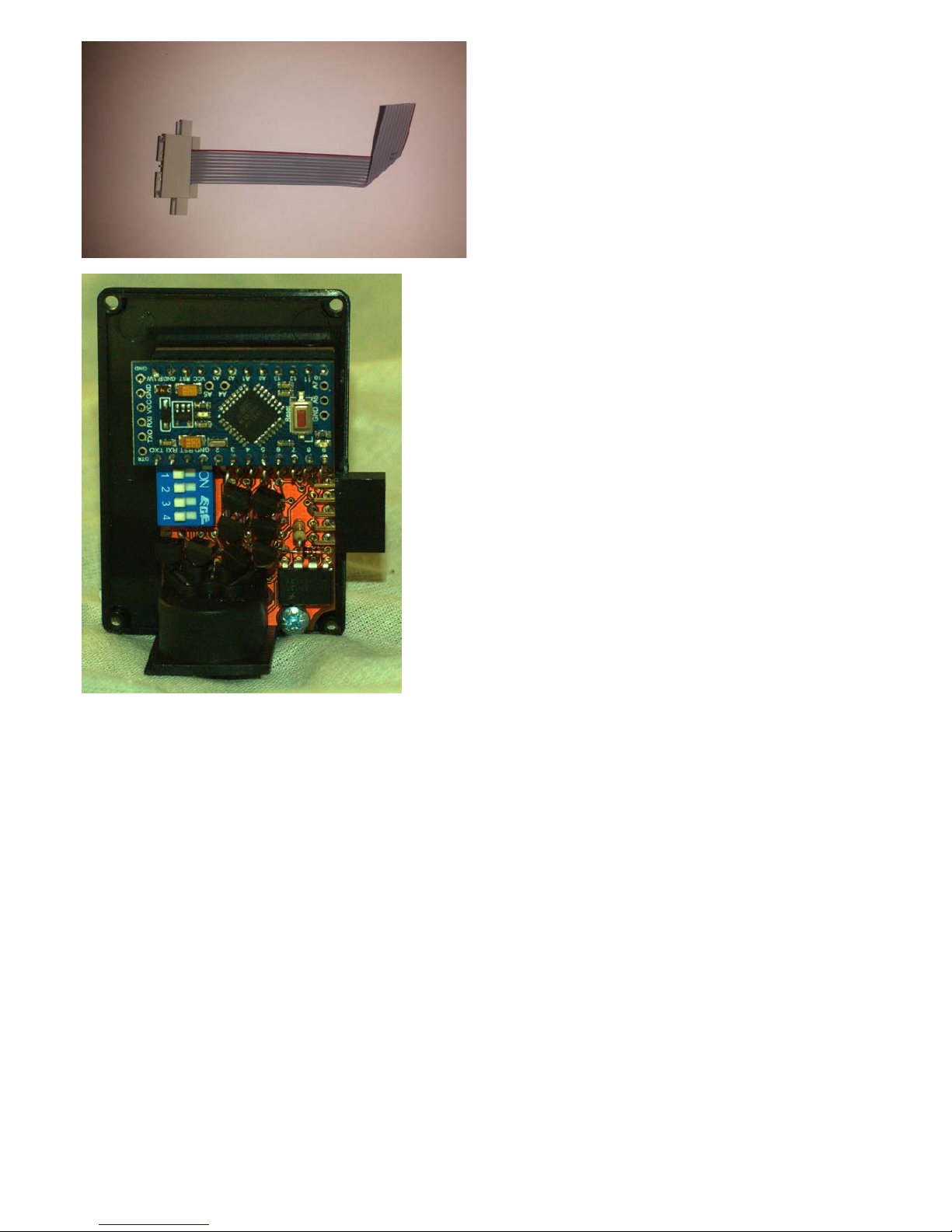
The converter comes in two parts - the unit itself and the connector to be installed in the DR-
110. The main unit comes either assembled or as a kit. With both, the connector needs to be
installed in the DR-110.
Tools required
• Screwdriver
• Soldering iron
• Drill
• File or preferably rotary tool
• Multimeter (recommended)
Constructing the Unit
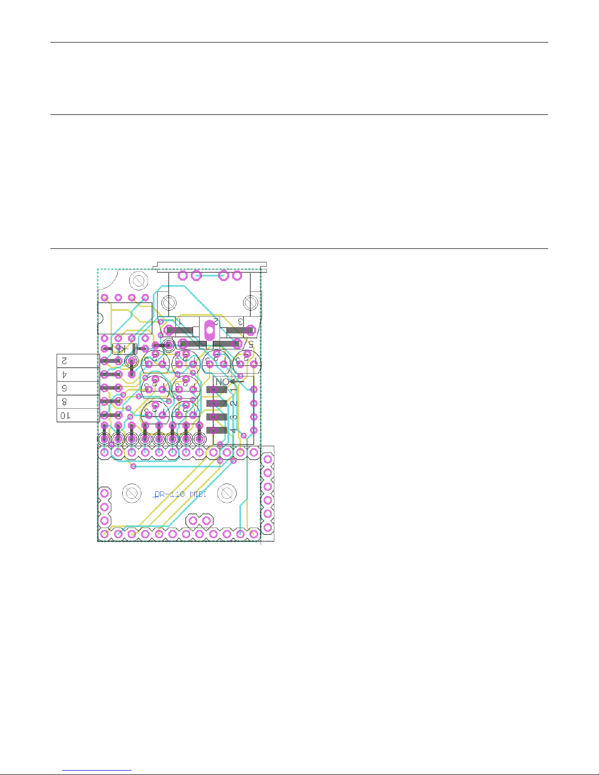
Solder the components to the PCB as per the
diagram to the left. The order of soldering is
not particularly important, but a good order
would be: large chip socket, 8 trigger resistors,
8 transistors, the diode, the 2 other resistors,
then the remaining chip, switch, MIDI port and
10-way connector.
The 8 resistors beside the chip and the one
beside the 10-way connector should all be
10kΩ (Brown Black Orange). The resistor
beside the MIDI port should 220Ω (Red Red
Brown).
The legs of the transistors must be bent to fit
in the holes. The easiest way is to line up two
legs into the correct holes and then turn the
transistor until the third lines up. The
transistors may sit at different heights
depending on how far they are pushed in.
The resistors can be inserted in either
direction, but the other components must be
inserted in the direction shown. Ensure the
black band of the diode faces towards the MIDI
port and the 8 pin chip has its dot aligned
towards the semicircle in the picture.
The controller chip can now be inserted for
testing.
2 V1.1
To ensure the PCB has been soldered correctly,
the next step is to make and then install the
connector for the DR-110 and check the two
units work together. This step is very delicate
and involves separating and stripping the end
of the wires of the ribbon cable so they line up
with the pins mentioned in the next section.
Refer to the next section for fitting it in the
unit.
The final step is to affix the PCB to the
enclosure. The controller chip will need to be
removed for this.
The PCB should be aligned with the enclosure
lid so the edge of the PCB is just within the lip
of the lid, as shown to the left. Guide marks
should be drawn onto the lid through the bolt
holes. These holes should then be drilled and
the PCB bolted in place. The three short bolts
included are for this. Care must be taken not to
tighten them too much as that could
potentially damage the board.
Once this is done, the controller chip can be
inserted into the socket.
Then the lid can be aligned with the case and
guide marks for the 10-way connector slot can
be made. There are many ways to remove the
plastic of the slot, but the fastest seems to be
to use wire cutters to cut away as much plastic
as possible and then file it down to neaten it
up. Once that is removed, the lid should fit into
the case.
Next, a hole can be made in the case for the
MIDI port. There is no simple way to locate the
hole other than measuring or estimating its
position. A stepped drill bit is the best way to
make the hole.
Finally, the lid and PCB can be screwed in place
onto the case.
3 V1.1

Installing the Connector
[!] Any user patterns saved in memory will be erased so write them down if you want to keep
them.
Remove the 3 screws on the base of the DR-
110. The back should now come off. Set this
aside for later.
The PCB will now be exposed. Solder the
ribbon cable so the red wire is connected to
the point labelled 6 on the image and the cable
runs towards the front of the DR-110. The wire
beside can be soldered to either point 7 or 8
and the other wires are to be soldered
sequentially from point 9 to 16. Once soldered,
it is important to check the continuity between
each adjacent pair of connections to ensure
they are not being bridged.
Once soldered, it should look similar to this. At
this stage, it is a good idea to connect the mod
to the unit to confirm it is working and
triggering the sounds properly. If it is not, the
soldering must be checked again and possibly
redone.
4 V1.1

Part of the PCB will need to be filed down
slightly to allow clearance for the bolts.
Remove a section of case and drill holes in
order to fit the connector
in the unit. The exact
position may vary based on how the cable has
been soldered so it is best to do this at this
stage.
Use the nuts and bolt to secure the connector.
Connect the DR-110 to the mod box.
5 V1.1

Operation
Playing Notes
Play notes as you would normally on your MIDI-equipped keyboard or digital sequence
generator, with the default keymapping below. By default, the unit will be set to channel 1.
Bass Drum
36
Hi-Hat Noise*
45
Rimshot
37
Open Hi-Hat
46
Snare Drum
38
Accent Hold*
47
Clap
39
Accent Trigger
48
Weak Clap
40
Cymbal
49
Snare Noise* 41 Cymbal Noise* 51
Closed Hi-Hat 42 Clap Noise* 52
Pedal Hi-Hat
44
Most sounds have no need to respond to Note Off events as they only trigger a short pulse, the
duration of which is set by the velocity of the note, creating a form of velocity sensitivity.
However, some sounds are sustained until a Note Off message is received. These sounds are
marked above with an asterisk and do not have velocity sensitivity.
Those sounds that do have velocity sensitivity are set so a velocity of 100 triggers each sound
the same way as the internal sequencer does.
Changing MIDI Channel
The MIDI channel can be set by either the internal switches, or MIDI CC.
Setting the channel by switch
The channel can be set using the switch positions below.
1
2 3 4 5 6 7
8
9
10
11
12
13
14
15
16
The position of the switches and the corresponding MIDI Channel
The unit will read these switches on startup if the channel has not been set previously by CC. It
will also be read if a CC9 with value 0 is received.
Setting the channel by CC
When a value of 1 - 16 is received on MIDI CC 9, the channel will be set to that value. Values 17+
have no effect. A value of 0 sets the MIDI channel the position of the switches. The MIDI channel
and omni status are saved when the device is switched off.
6 V1.1

Once the channel has been changed to another via CC, it will no longer respond to a CC on the
original channel. The sending equipment must have its send channel set the new channel of the
unit.
Omni mode can also be enabled or disabled, allowing the device to respond to messages sent
on any channel. To enable this, CC125 must be sent with a value of 0. To disable this, send
CC124 with a value of 0.
Changing the keymapping
To change which keys trigger which notes, send the CC in the implementation chart below
followed by the note number that should trigger it. For example, to change the open hi-hat so it
is triggered by the key to left of the default Bass Drum key, send CC46 with a value of 35. These
values are retained while the device is switched off.
MIDI Implementation
The unit does not transmit MIDI.
Channel
1-16
Mode
Omni / Mono
Note number
0-127
Velocity
0-127
CC
9
Set channel
36
Set Bass Drum note number
37
Set Rimshot note number
38
Set Snare Drum note number
39
Set Clap note number
40
Set Weak Clap note number
41 Set Snare Noise note number
42
Set Closed Hi-Hat note number
44
Set Pedal Hi-Hat note number
45
Set Hi-Hat Noise note number
46
Set Open Hi-Hat note number
47
Set Accent Hold note number
48 Set Accent Trigger note number
49
Set Cymbal note number
51
Set Cymbal Noise note number
52
Set Clap Noise note number
Aux
All notes off
7 V1.1
 Loading...