

Boss 210 DUS JD4045, IT4 74HP Service And Maintenance Manual
Service and
Maintenance
Manual
210 DUS JD4045
IT4 74HP
Air Compressor
This manual must be read carefully before using your Boss Industries, Inc. Air Compressor. Store in a safe and convenient location for future reference.
For technical support:
Phone: (800) 635-6587 (USA)
Phone: (219) 324-7776 (Outside USA)
Fax: (877) 254-4249 (USA)
Email: service@bossair.com
Website:
http://www.bossair.com
309416
05-03-2013 ARB

01/31/2012
2 309416

Contents
Manual Change History................................................................................................7
1.1 Revision List....................................................................................................7
Welcome........................................................................................................................8
2.1 General Information..........................................................................................8
2.2 Overview .........................................................................................................8
Safety...................................................................................................................9-13
3.1 General Safety Overview...................................................................................9
3.2 Safety Precautions..........................................................................................10
3.3 Safety and Information Decals..........................................................................12
Specifications..............................................................................................................14
4.1 Specification Sheet........................................................................................14
Description of Components..............................................................................15-18
5.1 Engine............................................................................................................15
5.2 Drive Coupling...............................................................................................15
5.3 Compressor Airend.......................................................................................15
5.4 Separator System..........................................................................................15
Separator Tank.........................................................................................15
Separator Element......................................................................................15
5.5 Pressure Relief Valve.....................................................................................16
5.6 Engine Air Filter..........................................................................................16
5.7 Compressor Air Filter.................................................................................16
5.8 Cooling Systems...........................................................................................16
Engine Radiator..........................................................................................16
Compressor Oil Cooler...............................................................................16
5.9 Compressor Oil Filter..................................................................................16
5.10 Compressor Oil Thermal Valve......................................................................16
5.11 Compressor Inlet Valve.................................................................................17
5.12 Minimum Pressure Valve...............................................................................17
5.13 Blowdown Valve..........................................................................................17
5.14 Blowdown Switch........................................................................................17
5.15 Discharge Pressure Regulator Valve...............................................................17
5.16 Instrument Panel...........................................................................................18
Engine Oil Pressure Gauge..........................................................................18
Engine Coolant Temperature Gauge............................................................18
Compressor Discharge Pressure Gauge......................................................18
Compressor Discharge Temperature Gauge................................................18
01/31/2012
3 309416

Contents
Description of Components (continued)............................................................15-18
5.15 Instrument Panel (continued).....................................................................18
Hourmeter.......................................................................................18
Tachometer.........................................................................................18
Voltmeter.................................................................................18
Unloader Valve...........................................................................................18
Emergency Stop Switch.............................................................................18
Bypass Switch...........................................................................................18
Ignition Switch...........................................................................................18
Installation.............................................................................................19-23
6.1 System Installation Overview...........................................................................19
6.2 Placing the Machine........................................................................................19
6.3 Connecting the System Fuel Supply.................................................................19
6.4 Fuel Specifications..........................................................................................20
High Altitude and Low Temperature Fuel....................................................20
Cold Weather Fuel.....................................................................................20
6.5 Connecting the Air Discharge Lines...............................................................20
6.6 Pre-Startup Inspection .................................................................................20
6.7 Machine Documentation...............................................................................21
6.8 Check Fluid Levels.......................................................................................21
6.9 Initial Startup Preparation..............................................................................21
6.10 Initial Startup.................................................................................................22
Operation.............................................................................................................23-24
7.1 Routine Operating Procedures........................................................................23
Routine Startup Preparation........................................................................23
Routine Startup Procedure.........................................................................23
Routine Shutdown Procedure.....................................................................23
7.2 Emergency Shutdown Procedure..........................................................24
Maintenance........................................................................................................25-36
8.1 Maintenance Overview....................................................................................25
8.2 Maintenance Schedule....................................................................................25
8.3 Recommended Spare Parts List......................................................................26
8.4 Parts and Service Contact Information............................................................26
8.5 Maintenance Log............................................................................................27
01/31/2012
4 309416

Contents
Maintenance (continued)....................................................................................25-36
8.6 Separator Element Replacement......................................................................28
8.7 Engine Air Filter Replacement..........................................................................29
8.8 Compressor Air Filter Replacement.................................................................30
8.9 Compressor Oil..............................................................................................31
Specifications.......................................................................................31
Adding Compressor Oil.............................................................................32
Changing Compressor Oil..........................................................................32
8.10 Compressor Oil Cooler.................................................................................33
8.11 Compressor Oil Filter....................................................................................33
8.12 Engine Cooling System Maintenance..............................................................34
Engine Coolant...........................................................................................34
Engine Radiator..........................................................................................34
Engine Fan.................................................................................................35
Engine Serpentine Belt...............................................................................35
8.13 Battery..........................................................................................................35
8.14 Standby Pressure Adjustment (For 100 PSI System).....................................35
8.15 Idle Speed Adjustment..................................................................................36
8.16 Rated Speed Adjustment...............................................................................36
Troubleshooting...................................................................................................37-40
9.1 Troubleshooting Chart....................................................................................37
9.2 Parts and Service Contact Information............................................................40
Warranty..............................................................................................................41-45
10.1 Warranty Policy............................................................................................41
10.2 Summary of Main Warranty Provisions..........................................................42
10.3 Warranty/Return Goods Instructions.............................................................43
10.4 Warranty Claims - Preparation of Part Return.................................................43
10.5 Return or Warranty Claims - Filing Procedures...............................................43
10.6 Warranty Claims Provisions..........................................................................44
10.7 Damage in Transit..........................................................................................44
10.8 Screw Compressor Airend Exchange Program..............................................45
Parts and Illustration Section...........................................................................46-63
11.1 Frame System...............................................................................................46
11.2 Engine System..............................................................................................48
11.3 Compressor System.....................................................................................50
11.4 Discharge System..........................................................................................52
01/31/2012
5 309416

Contents
Parts and Illustration Section (continued)........................................................46-63
11.5 Cooling System..........................................................................................54
11.6 Electrical System.......................................................................................56
11.7 Canopy System.......................................................................................58
11.8 Decal System..............................................................................................60
11.9 Hose System......................................................................................62
11.10 System Wiring Diagram..............................................................................63
01/31/2012
6 309416

Manual Change History
ETAD NOITACOL EGNAHCFONOITPIRCSED SLAITINI
1.1 Revision List
01/31/2012
7 309416
Welcome
This manual must be read carefully before using your Boss Industries, Inc. Air Compressor. Store in a safe and convenient location for future reference.
For technical support:
Phone: (800) 635-6587 (USA)
Phone: (219) 324-7776 (Outside USA)
Fax: (877) 254-4249 (USA)
Email: service@bossair.com
Website:
http://www.bossair.com
Service and
Maintenance
Manual
210 DUS JD4045
IT4 74HP
Air Compressor
309416
01/31/2012
2.1 General Information
Thank you for choosing the 210 DUS Air Compressor. Before operating
this system, read over this manual and become well acquainted with your
new machine. Doing this will increase your safety and maximize the life
of the machine.
While this manual is written to be as accurate as possible, Boss Industries, Inc. strives to continually improve the efficiency and performance of
its machines. As a result, sometimes there may be slight differences
between a given version of the manual and the machine.
2.2 Overview
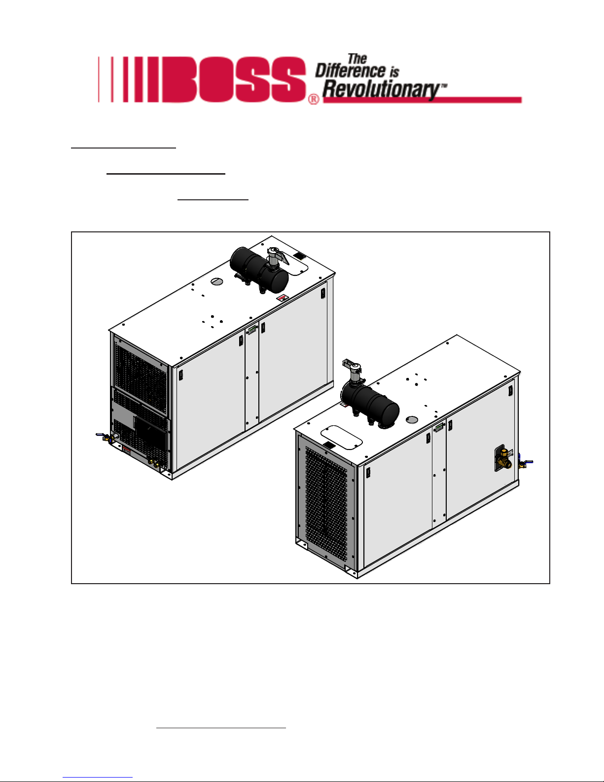
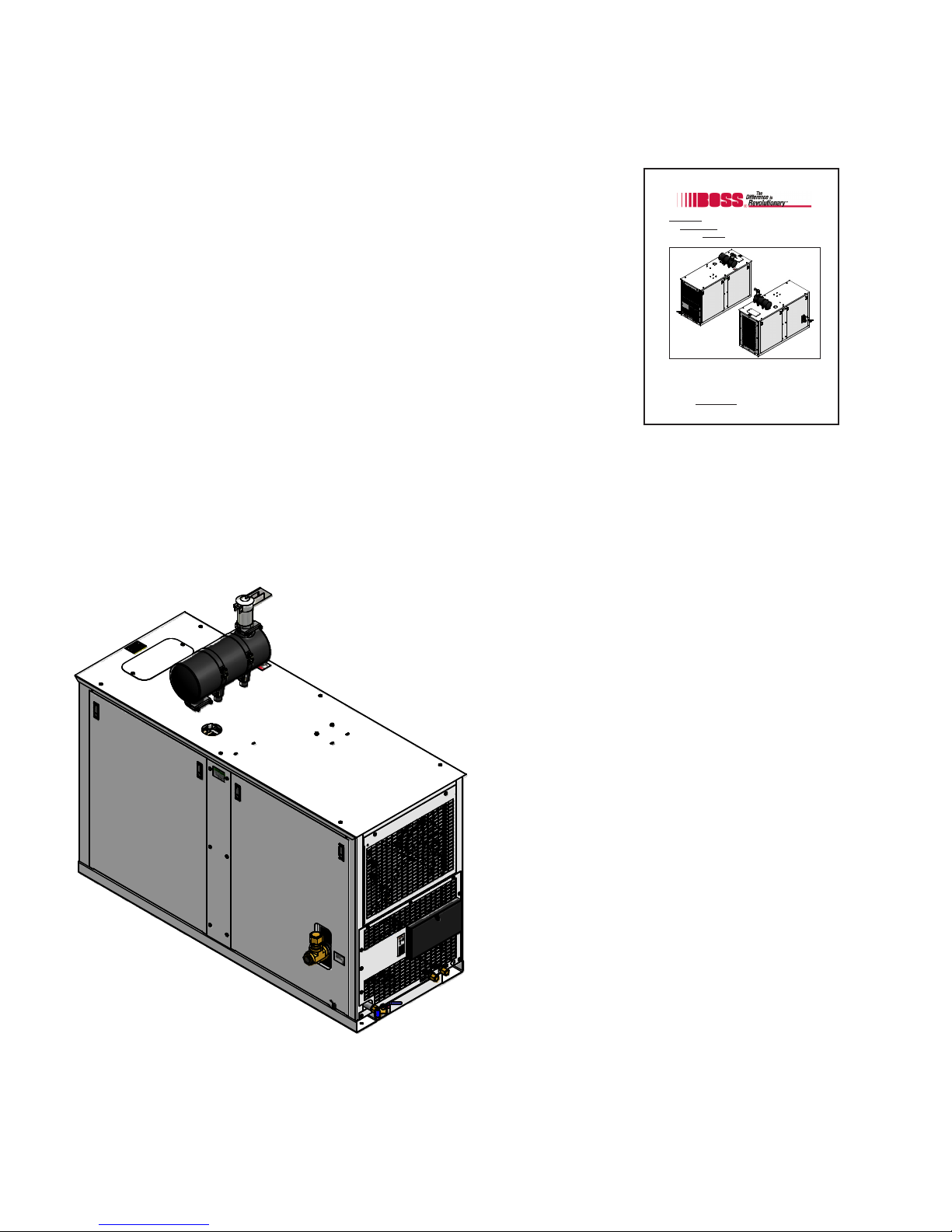
The 210 DUS Air Compressor is a compact, strategically designed system. It integrates all major
components on a single frame, which is enclosed in a tough, weather-resistant canopy.
The 210 DUS Air Compressor’s rotary screw
design guarantees continuous air output of up to
210 CFM (cubic feet per minute) at 100 PSI
(pounds per square inch). With remote fluid
drains and removable doors, virtually all
components are accessible for maintenance and
service. The instrument panel clearly displays
pressures, temperatures, and hours of operation.
Other features, including a spin-on compressor oil
filter and a drop-in separator element, reduce the
time and costs associated with routine
maintenance.
The 210 DUS Air Compressor also has enhanced
safety features to protect your valuable resources:
minimum pressure valve, high compressor oil
temperature shutdown, high discharge pressure
shutdown, automatic blowdown device, pressure
relief valve, high engine coolant temperature, low
engine oil pressure, and clearly displayed warning/
information decals.
01/31/2012
8 309416

Safety
3.1 General Safety Overview
Remember, safety is basically common sense. While there are standard safety rules, each situation has
its own peculiarities that cannot always be covered by rules. Therefore with your experience and
common sense, you are in a position to ensure the safety of yourself and others. Lack of attention to
safety can result in: accidents, personal injury, reduction in efficiency, and worst of all – Loss of Life.
Watch for safety hazards and correct them promptly.
Understanding the proper operation of this equipment is critical to its safe operation. The owner, lessor,
and/or operator of this equipment is hereby notified and forewarned that any failure to observe the
safety and operating guidelines may result in injury and/or damage. Boss Industries, Inc. expressly
disclaims responsibility or liability for any injury or damage caused by failure to observe these specified
precautions or by failure to exercise the ordinary caution and due care required while operating or
handling this equipment, even though not expressly specified.
In addition to following these safety guidelines, the operator should follow any company specific guidelines and procedures. Consult your immediate supervisor for specific company safety guidelines and/or
procedures.
The following safety symbols are used throughout this manual to draw attention to important information.
If the information is not carefully read and the instructions are not followed, severe injury, death, and/or
damage to property and equipment may occur.
Indicate[s] an imminently hazardous situation, which, if
not avoided, will result in death or serious injury.
Indicate[s] a potentially hazardous situation, which, if not
avoided, could result in death or serious injury.
Indicate[s] a potentially hazardous situation, which, if not
avoided, could result in minor or moderate injury.
Indicate[s] a potentially unsafe situation or practice,
which, if not avoided, can result in property and/or
equipment damage only.
01/31/2012
9 309416

Safety
3.2 Safety Precautions
The following safety precautions are a general guide to safe operation of the equipment.
This is a pressurized system. Do not attempt to remove
any part of this machine without first completely relieving
entire system of pressure. Do not attempt to service any
part of the equipment while in operation. Never attempt
to repair or modify any pressure vessel or device.
System contains hot oil. The system must be shut off prior
to servicing. Then permit system to cool down prior to
adding compressor oil or servicing the unit.
Do not use air from this system for breathing or food
processing. Air from this system will cause severe injury
or death if used for breathing or food processing.
The system is designed to compress air. Do not attempt
to compress other gases. Compression of other gases
may create a situation where an explosion or fire may
occur.
Do not use flammable solvents for cleaning system components as this can cause the unit to ignite or explode
during operation. Keep combustibles out of and away
from system inlets and any associated enclosures.
Never disable, override, or remove safeties, either temporarily or permanently.
Do not modify systems to operate equipment at a higher
pressure than specified.
01/31/2012
Never operate the machine in an enclosed area.
10 309416

3.2 Safety Precautions (continued)
Safety
Read and understand this manual and all other safety
instructions before using this equipment. Failure to follow
operating instructions and/or failure to follow maintenance
procedures and intervals could result in personal injury,
death, and/or damage to equipment and property.
Use only Boss Industries, Inc. approved replacement
parts.
Never place machine on a grade more than 15 degrees.
Keep doors closed on the machine during operation.
Check engine’s operator manual for required service
and maintenance intervals.
This machine is equipped with safety unloading
system to prevent damage to the compressor drive
coupling. Should an attempt be made to start this
system improperly, the machine will run unloaded for
60 seconds. Likewise, if an attempt is made to
shutdown the system improperly, the unit will continue to run until the compressor system pressure
unloads below 50 PSI.
01/31/2012
11 309416
Safety
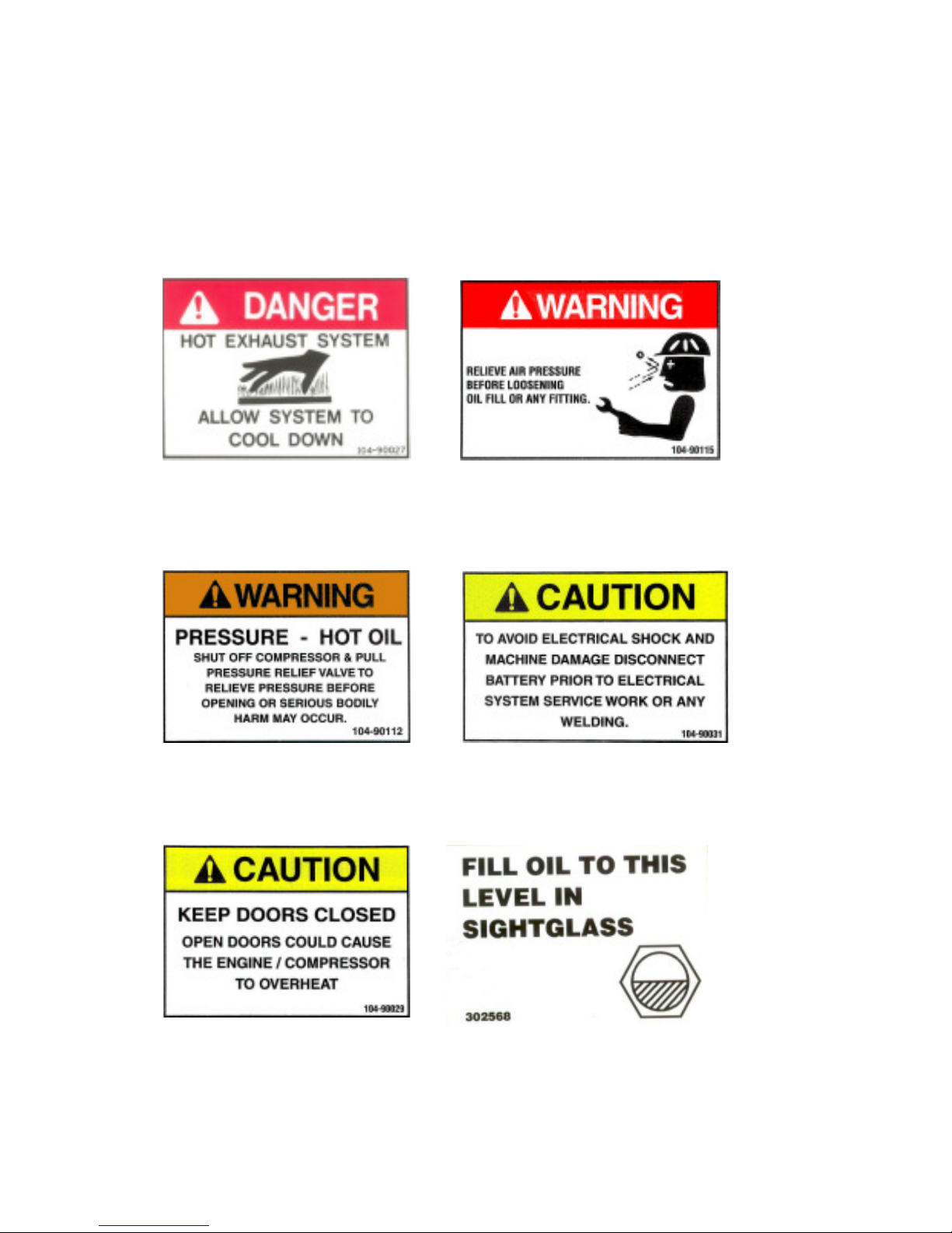
3.3 Safety and Information Decals
This machine is supplied with a full complement of safety and identification decals. These decals are
affixed to the unit during final assembly. These decals must be clearly visible and undamaged. Should
any of these decals become illegible or damaged, immediately replace the decal.
Hot Exhaust Pressurized System
Electrical ShockHot Pressurized Oil
Close Doors Oil Level
12 309416
01/31/2012
Safety
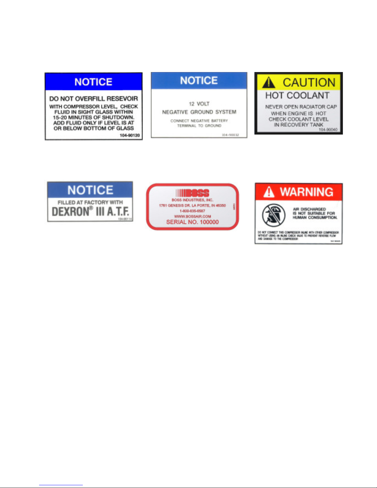
3.3 Safety and Information Decals (continued)
Overfill Negative Ground System
Compressor Oil
Hot Coolant
Serial Tag
Breathing Air
01/31/2012
13 309416
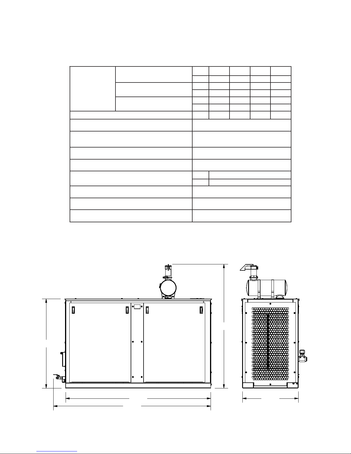
4.1 Specification Sheet
yticapaC
ISP001@
MFC 571 581 002 012
PH 83 14 54 74
ISP521@
MFC 471 481 991 902
PH 44 74 25 55
ISP061@
MFC 071 181 891 402
PH 84 15 65 75
deepStupnIrosserpmoC
MPR 0002 5212 5232 0042
dneriArosserpmoC oitaRraeG50.3htiwG01ACS
enignE
47
PH
DJ
5404
MIRTNI
REIT
4
EAS/W
B
EVIRDXUA
metsySlacirtcelEenignE CDV21
snoisnemiDesaB "2/107X"03X"8/548
knaTleuFleseiDlanoitpO
PAC L041,.LAG73
MID "5.6X"03X"87
elgnAgnitarepOenihcaM mumixam°51
elcyCytuD suounitnoC
snoitidnoCtneibmA F°521otF°04-
66.77
48.07
78.00
84.55
30.00
Specifications
*SPECIFICATIONS SUBJECT TO CHANGE WITHOUT PRIOR NOTICE*
01/31/2012
14 309416

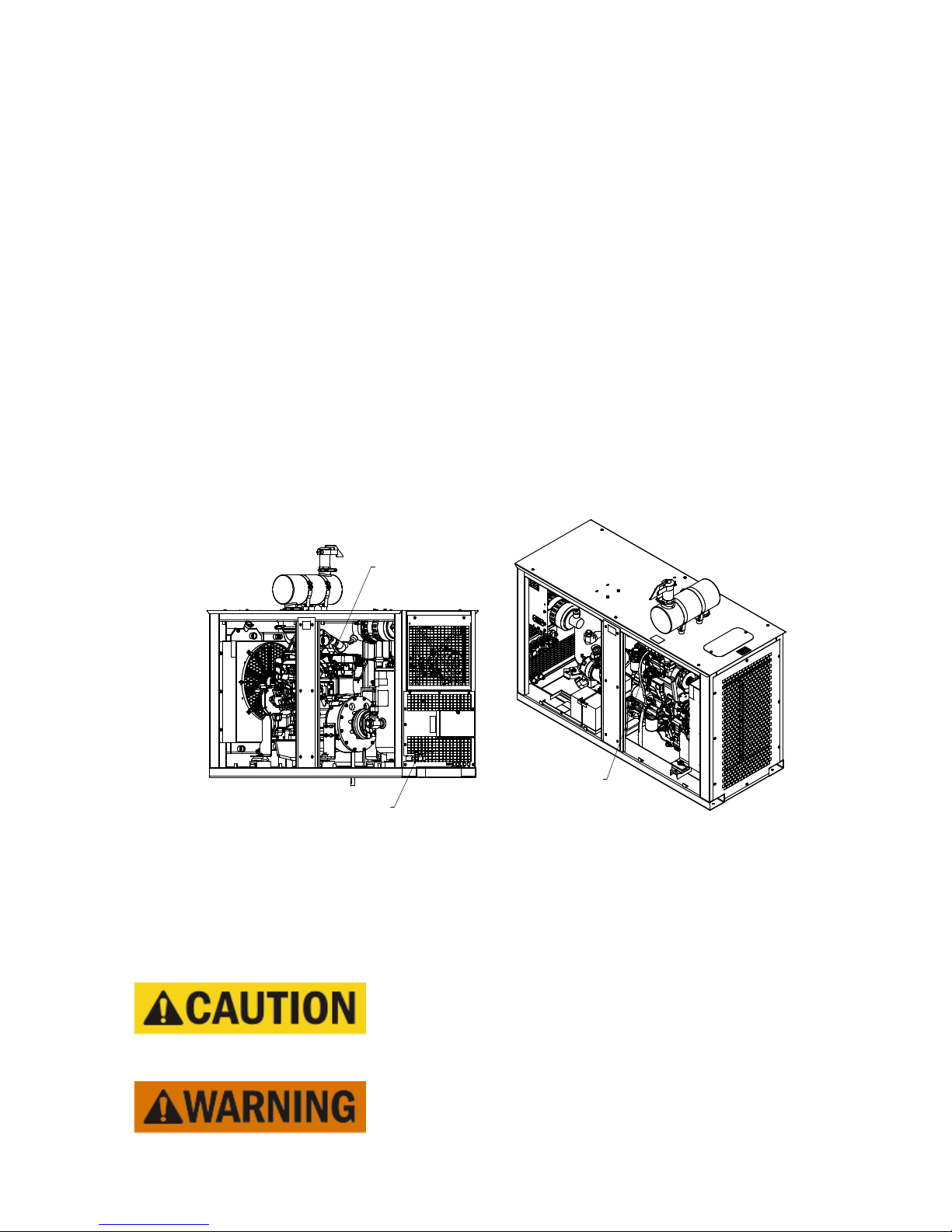
Description of Components
5.1Engine
The 210 DUS Air Compressor contains a John Deere, 4 cylinder diesel engine. This engine has been
selected to handle the rugged duty required for its operation. The engine speed is regulated by a
pneumatic throttle control.
5.2Drive Coupling
Power from the engine is transmitted to the compressor input shaft through a specially designed drive
coupling. The drive coupling consists of a highly torsionally flexible rubber disc that mates with an
engine flywheel flange. The coupling provides a torque limitation to protect from system overloads.
5.3 Compressor Airend
The Boss Industries, Inc. compressor airend is a positive displacement, oil flooded, rotary screw type
unit employing one stage of compression to achieve the desired pressure. Components include a
housing (stator), two screws (rotors), bearings, and bearing supports. Power from the engine flywheel
is transferred through a gear set to the male rotor. The female rotor is driven by the male rotor. There
are five lobes on the male rotor while the female rotor has six roots.
rotors mesh to compress air. Inlet air is trapped as the male lobes roll down the female grooves,
pushing trapped air along, compressing it until it reaches the discharge port at the end of the stator which
delivers smooth-flowing, pulse-free air. Being an oil flooded system, the oil serves three purposes:
lubricates the rotating parts and bearings, serves as a cooling agent for the compressed air, and seals the
running clearances.
In operation, two helical grooved
5.4 Separator System
I. Separator Tank
From the compressor airend, the compressed air and hot oil flow into a steel, ASME coded,
pressure vessel, rated at 250 PSI, that acts as an oil reservoir. This tank is the first of two stages in
separating the oil and compressed air mixture. From the bottom of the separator tank, oil is forced
to the oil filter.
II. Separator Element
At the top of the separator tank is the separator element. The separator element removes the oil
mist from the air as it is passed on to the minimum pressure valve. As the air/oil mist passes through
the outside of the media, oil gathers on the interior walls and settles to the bottom of the element.
Collected oil is returned to the compressor airend through the oil return line. The separator will filter
the oil concentration in the air to less than 3 parts per million.
15 309416
01/31/2012

Description of Components
5.5 Pressure Relief Valve
This valve vents separator tank pressure to atmosphere should the pressure inside the tank exceed 200
PSI.
5.6 Engine Air Filter
The engine air filter is a two stage, dry type intake filter with a gravity evacuator and replaceable internal
element. On the outlet of the engine air filter is an air filter restriction indicator. This indicator serves as
a maintenance tool.
5.7 Compressor Air Filter
The compressor air filter is a two stage, dry type intake filter with a gravity evacuator and replaceable
internal element. On the outlet of the compressor air filter is an air filter restriction indicator. This
indicator serves as a maintenance tool.
5.8 Cooling Systems
I. Engine Radiator
The radiator is designed to dissipate the heat load of the engine and is mounted in front of the
specially selected engine fan. Hot engine coolant is passed through the interior of the radiator and
heat is transferred to the air that passes across the cooling fins.
II. Compressor Oil Cooler
The compressor oil cooler is designed to dissipate the heat created during the compression of air.
The oil cooler is mounted beside the engine radiator. This works similar to the engine radiator but is
designed to withstand the full compressor system working pressure.
5.9 Compressor Oil Filter
The compressor oil filter is a full flow, spin-on canister. It has been specially designed to handle 200
PSI. The oil filter is mounted downstream of the separator tank to ensure all contaminants are prevented from being passed on to the compressor oil cooler.
5.10 Compressor Oil Thermal Valve
The compressor oil thermal valve is a thermostatically controlled by-pass valve that allows varying
amounts of oil, depending upon the temperature, to by-pass the oil cooler. The oil thermal valve directs
oil flow back to the compressor airend until the system reaches 170°F. Once at system operating
temperature, the valve shifts, directing the flow through the oil cooler before returning to the compressor
airend.
01/31/2012
16 309416

Description of Components
5.11 Compressor Inlet Valve
The compressor inlet valve is a normally open air intake valve bolted to the compressor airend. When
the system is shut down, this valve also acts as a check valve that prevents the air/oil mixture within the
compressor airend from entering the inlet piping.
5.12 Minimum Pressure Valve
To ensure there is adequate pressure to produce proper oil flow throughout the system, a spring loaded,
normally closed minimum pressure valve is set to maintain at least 80 PSI in the separator tank.
5.13 Blowdown Valve
The blowdown valve is a shuttle valve that vents system pressure to atmosphere when the system is shut
down. This is done to prevent the high torque load that would be required to overcome the static
pressure. The blowdown valve is stamped with an “I” and a “P”. The “I” side is connected to dry air
from the separator tank, and the “P” side is the pilot signal coming from the compressor inlet valve.
5.14 Blowdown Switch
The system is equipped with a blowdown switch. This switch will sense pressure in the pilot signal to
the blowdown valve. If the system contains pressure, the switch will prevent the machine from starting.
This will prevent premature damage to the drive coupling.
5.15 Discharge Pressure Regulator Valve
This valve, located downstream of the separator element, is used to set the desired discharge pressure.
This valve will send a pneumatic signal to the inlet valve to start closing when the pressure exceeds the
setpoint. This signal will also adjust the speed of the engine. This system has a maximum operating
pressure of 160 PSI.
Most air tools operating pressure range is between 90 and 125
PSI. Operating above the tools recommended pressures will
decrease the life of the tool. Strictly adhere to tool operating
pressures and torque standards set forth by the tool
manufacturer.
01/31/2012
17 309416

Description of Components
5.16 Instrument Panel
The 210 DUS Air Compressor incorporates an instrument panel that includes numerous gauges and
controls in a single, easy to access location.
I. Engine Oil Pressure Gauge
This feature displays the oil pressure inside the engine block. When the pressure drops below 20
PSI, the system will shut down. During operation, the engine oil pressure should be approximately
60 PSI to 80 PSI.
II. Engine Coolant Temperature Gauge
This feature displays the temperature of the engine coolant. When the temperature reaches 235°F,
the system will shut down. During operation, the temperature should be approximately 190°F to
210°F.
III. Compressor Discharge Pressure Gauge
This feature displays the pressure downstream of the airend.
IV. Compressor Discharge Temperature Gauge
This feature displays the compressor discharge temperature. When the temperature reaches 245°F,
the system will shut down. During operation, the discharge temperature should be approximately
170°F to 190°F.
V. Hourmeter
The hourmeter records the total number of operating hours. It serves as a guide in following the
recommended maintenance schedule. The hourmeter will only run when the engine is operating.
VI. Voltmeter
This feature displays the voltage of the battery. The voltmeter will display when the ignition switch is
in the “RUN” position. During operation, the voltmeter should be approximately 14 VDC.
VII. Unloader Valve
This turn valve is used to limit the compressor system pressure. When the valve is in the loaded
position, the system will build to the regulator setting. If the valve is set to unloaded, the system will
build to approximately 45 PSI.
VIII. Emergency Stop Switch
The system is equipped with an emergency stop switch to immediately shutdown the machine.
IX. Bypass Switch
The bypass switch will temporarily disable the engine oil pressure shutdown during startup.
X. Ignition Switch
The ignition switch is used for starting and stopping the machine.
01/31/2012
18 309416
Installation
1/4" TUBE
FUEL SUPPLY
(2) 3/4" MNPT AIR
SERVICE VALVES
5/16" TUBE
FUEL RETURN
6.1 System Installation Overview
The 210 DUS Air Compressor should be installed only by those who have been delegated to do so,
trained, and who have read and understand this manual. Failure to follow the instructions, procedures,
and safety precautions in this manual may result in accidents and injuries.
Install, use, and operate this system only in full compliance with all pertinent O.S.H.A., Federal, State,
and Local codes or requirements, in addition to Boss Industries, Inc. and any company’s regulations.
Do not modify this system except with written factory approval.
6.2 Placing The Machine
The first step in installing the 210 DUS Air Compressor is placing the system on a solid, level surface.
This machine is designed to run at up to a 15° grade maximum. The machine must be supplied ample
ambient air, as the system will overheat if the cooling air intake’s temperature exceeds ambient conditions.
6.3 Connecting the System Fuel Supply
Connect the fuel supply line to the 1/4” tube port on the starter side of the engine. Connect the fuel
return line to the 5/16” tube port, near the air inlet side of the turbo. Both tubes need to be SAE
30R7 rated fuel lines.
01/31/2012
Due to the precise tolerances of diesel injection systems, it is
extremely important that the fuel be kept clean and free from
dirt or water. Dirt or water in the system can cause severe
damage to both the injection pump and the injection nozzle.
Do not mix gasoline or alcohol with diesel fuel. This mixture can cause an explosion.
19 309416
 Loading...