

Page 1

HS-4000
Half 486 Little Board
PCI Slot, PC/104 Bus, Flat Panel Connector,
100-Base Network, RS-232/422/485.
Page 2

Copyrights
This manual is copyrighted and all rights are reserved. It is not allow any non authorization
in copied, photocopied, translated or reproduced to any electronic or machine readable
form in whole or in part without prior written consent from the manufacturer.
In general, the manufacturer will not be liable for any direct, indirect, special,
incidental or consequential damages arising from the use of inability to use the
product or documentation, even if advised of the possibility of such damages.
The manufacturer keeps the rights in the subject to change the contents of this
manual without prior notices in order to improve the function design,
performance, quality and reliability. The author assumes no responsibility for
any errors or omissions, which may appear in this manual, nor does it make a
commitment to update the information contained herein.
Trademarks
BOSER is a registered trademark of BOSER Technology Co., Ltd.
Award is a registered trademark of Award Software, Inc.
ISB is a registered trademark of BOSER Technology Co., Ltd.
All other trademarks, products and or product's name mentioned herein are
mentioned for identification purposes only, and may be trademarks and/or
registered trademarks of their respective companies or owners.
© Copyright 1998
All Rights Reserved.
User Manual edition 1. 5, Aug.24 2001
Page 3

CONTENTS
GENERAL INFORMATION..........................................................................................3
1.1 MAJOR FEATURES ..................................................................................................4
1.2 SPECIFICATIONS .....................................................................................................5
1.3 DELIVERY PACKAGE ..............................................................................................6
HARDWARE INSTALLATION....................................................................................7
2.1 CAUTION OF STATIC ELECTRICITY....................................................................7
2.2 CAUTION ON UNPACKING AND BEFORE INSTALLATION................................8
2.3 HS-4000’S LAYOUT.................................................................................................9
2.4 QUICK LISTING OF JUMPERS...............................................................................10
2.5 QUICK LISTING OF CONNECTORS.......................................................................10
2.6 JUMPER SETTING DESCRIPTION........................................................................12
2.7 SETTING THE CPU OF HS-4000..........................................................................13
2.8 CMOS DATA CLEAR............................................................................................14
2.9 CACHE SIZE SELECT ............................................................................................14
2.10 SYSTEM MEMORY DRAM................................................................................15
2.11 WATCH-DOG TIMER ..........................................................................................15
2.12 VGA CONTROLLER.............................................................................................17
2.13 DISKONCHIP? ADDRESS SETTING.................................................................18
CONNECTION...............................................................................................................19
3.1 THE FLOPPY DISK DRIVE CONNECTOR ............................................................19
3.2 PCI E -IDE DRIVE CONNECTOR ...........................................................................20
3.3 PARALLEL PORT CONNECTOR ...........................................................................21
3.4 SERIAL PORTS CONNECTORS..............................................................................22
3.5 KEYBOARD & MOUSE CONNECTOR ..................................................................24
3.6 POWER'S LED, FAN AND KEY-LOCK CONNECTORS .......................................24
3.7 DC MAIN AND AUX. POWER CONNECTORS ....................................................25
3.8 E XTERNAL FRONT PANEL CONNECTOR..........................................................25
3.9 PS/2 MOUSE IRQ12 SELECTION CONNECTOR .................................................26
3.10 VGA CONNECTOR...............................................................................................26
3.11 FAST ETHERNET CONNECTOR .........................................................................27
3.12 PC/104 BUS CONNECTION.................................................................................27
3.13 FLAT -PANEL CONNECTOR................................................................................29
Connections for four standard LCDs................................................................30
Contents ? i
Page 4

AMI BIOS SETUP .........................................................................................................35
4.1 MAIN MENU ..........................................................................................................36
4.2 STANDARD CMOS SETUP ..................................................................................37
4.3 ADVANCED CMOS SETUP..................................................................................38
4.4 ADVANCED CHIPSET SETUP ..............................................................................40
4.5 POWER MANAGEMENT SETUP..........................................................................41
4.6 PERIPHERAL SETUP.............................................................................................42
A BRIEF BROWSE OF 100 BASE-T LAN RTL-8139’S INSTALLATION
SOFTWARE...................................................................................................................43
5.1 TEXT FILES LIST OF HELP DOCUMENTS...........................................................44
5.2 DISKETTE CONTENTS..........................................................................................44
5.3 FILES ON CONFIGURATION DISK........................................................................45
5.4 INSTALLING NOVELL NETWORK DRIVERS TO
WORKSTATION FOR DOS ODI CLIENT ...........................................................48
5.5 SERVER DRIVER FOR NET WARE 3.12................................................................50
5.6 SERVER DRIVER FOR NET WARE 4.1..................................................................51
5.7 SERVER DRIVER FOR NET WARE 4.11................................................................53
5.8 CLIENT 32 FOR WINDOWS 95.............................................................................54
5.9 INSTALLING IBM NETWORK DRIVERS TO
LAN SERVER FOR OS/2 2.3.................................................................................56
5.10 LAN SERVER FOR OS/2 4.0................................................................................59
5.11 INSTALLING MICROSOFT NETWORK DRI VERS TO
MICROSOFT NETWORK CLIENT FOR DOS...................................................60
5.12 LAN MANAGER WORKSTATION / SERVER....................................................63
5.13 WINDOWS FOR WORKGROUPS V3.0.................................................................64
5.14 WINDOWS NT 3.5, 3.51, & 4.0...........................................................................67
5.15 WINDOWS 95 & OSR2........................................................................................68
5.16 INSTALLING UNIX NETWORK DRIVERS TO SCO UNIX 4.X.........................68
5.17 SCO UNIX 5.X.....................................................................................................70
5.18 OTHER NTEWORK OF OPERATING SYSTEM INFORMATION
OF PACKET DRIVER..........................................................................................72
5.19 LANTASTIC 6.0 WITH NDIS DRIVER...............................................................73
ii ? Contents
Page 5

Chapter-1
General Information
The HS-4000 is an all-in-one half size industrial single board with design in Novell
NE2000 compatible 32-bit PCI bus Ethernet, provides 100 BASE-T or 10 BASE-T
for directly network automation demand.
Supports for various 40-133 MHz 80486SX/DX/DX2/DX4, 5x86 CPUs with
32-bit data bus and processing ability. Up to 64MB RAM by 72-pin SIMM
supported. Provides "DiskOnChip? " socket supported memory size up to 24 MB.
Design in with on board 1MB memory VGA architecture, supports direct interface to
color and monochrome Single Drive (SD) and Dual Drive (DD) STN, TFT & EL
panels and resolutions up to 1024x768 256 colors to CRT monitor.
The HS-4000 support completed with all necessary I/O for industrial application. A
PCI enhanced IDE for two ATA-2 IDE drivers; supports up to two floppy disk
drivers; provide three high speed serial RS-232 ports and one RS232/422/485 port
with compatible to 16C550 UART with 16-byte FIFO; one enhanced bi-directional
parallel port which support SPP/EPP/ECP. The board also provides keyboard and
PS/2 mouse connector, PC/104 connector and one standard PCI slot etc.
3
Page 6

1.1 Major Features
?? 80486SX/DX/DX2/DX4, 5x86 CPU supported.
?? ALi 1487/1489 chipset.
?? Supports DRAM up to 64 MB.
?? Fast PCI enhanced IDE controller supports two IDE drives.
?? Three high-speed serial RS-232 ports and one RS232/422/485 selectable port
(supports 16C550 UART with 16-byte FIFO).
?? One enhanced bi-directional parallel port supports SPP/EPP/ECP.
?? Keyboard and PS/2 Mouse connector.
?? On-board ALi M5113 Super I/O.
?? On-board 32 bit PCI-BUS VGA/ Panel controller.
?? "DiskOnChip™" Socket Supported Memory Size up to 24 MB.
?? On-board 32 bit PCI bus Ethernet, Novell NE2000 compatible.
?? Supports PC/104 connector.
?? One standard PCI slot.
4
Page 7

1.2 Specifications
?? CPU: 80486SX/DX/DX2/DX4/5X86.
?? Bus interface: PCI bus
?? Chipset: ALi 1487/1489
?? Data bus: 32-bit
?? Processing ability: 32-bit
?? PCI Flat Panel / VGA Controller: VGA Chipset with 1 MB memory
interface to color and monochrome Single Drive (SS) and Dual Drive (DD)
STN, TFT & EL panels. Support CRT resolutions up to 1024x768 256
colors.
?? PCI Enhanced IDE interfaces: Supports up to two enhanced IDE
ATA-2).
?? RAM memory: Up to 64MB, uses two 72-pin SIMM sockets.
?? Cache memory: On board 128KB 2nd level cache.
?? Floppy disk drive interface: Supports up to two floppy disk drives.
?? Parallel port: One parallel port supports SPP/ECP/EPP.
?? Serial port: Three RS-232 ports one RS232/422/485 port supports
16C550 UART with 16-byte FIFO.
?? BIOS: AWARD flash BIOS.
?? Watchdog timer: Hardware circuit can be set by 1, 2, 10, 20, 110, or 220
seconds period Reset or NMI was generated when CPU did not periodically
trigger the timer.
?? Ethernet: Realtek RTL 8139, 32 bit PCI bus Ethernet, Novell NE2000
compatible.
?? Keyboard / Mouse connector: 8-pin connector supports standard
PC/AT keyboard and a PS/2 mouse.
?? PC/104: 104-pin connector support 16 bit ISA Bus.
?? PCI slot: Standard PCI bus expansion slot.
?? Flash memory Disk: Reserved socket for "DiskOnChip™", support up to
24MB Flash memory disk.
5
Page 8

?? Power connector: Support 4-PIN power connector input (+5V, +12V).
?? CMOS: Real-time clock/calendar and battery backup by DS12B887 or
equivalent device.
?? Power supply voltage: +5V±5%, +12V±5%.
?? Max. Power requirement: +5V @2.2A.
?? Operating temperature: 0-55°C (CPU need cooler).
?? Board size: 8" (L) x 5.75" (W) (203mm x 146mm).
1.3 Delivery Package
The delivery package of HS-4000 includes all following items:
?? HS-4000 Industrial Single Board
?? Printer port Flat Cable
?? IDE port Flat Cable
?? FDD port Flat Cable
?? 40-pin COM ports Cable
?? Flat Panel Cable
?? Front Panel Cable
?? Ethernet Cable
?? PS/2 Mouse and Keyboard Transfer Cable
?? Utility Diskette
?? User’s Manual
Please contact with your dealer if any of these items are missing or damaged
when purchasing. And please keep all parts of the delivery package with
packing materials in case of you want to ship or store the product in feature.
6
Page 9

Chapter-2
Hardware Installation
This chapter provides the information on how to install the hardware of
HS-4000. At first, please follow up sections 1.3, 2.1 and 2.2 in check the
delivery package and carefully unpacking. Following after, the jumpers setting
of switch, watchdog timer, and the DiskOnChip? address selection.
2.1 Caution of Static Electricity
The HS-4000 has been well package with a anti-static bag in protect its
sensitive computer components and circuitry from the damage of static
electric discharge.
Note: DO NOT TOUCH THE BOARD OR ANY OTHER SENSITIVE
COMPONENTS WITHOUT ALL NECESSARY ANTI-STATIC
PROTECTION.
You should follow the steps as following to protect the board in against the
static electric discharge whenever you handle the board:
1. Please use a grounding wrist strap on whoever needs to handle the
HS-4000. Well clip the ALLIGATOR clip of the strap to the end of the
shielded wire lead from a grounded object. Please put on and connect the
strap before handle the HS-4000 for harmlessly discharge any static
electricity through the strap.
2. Please use anti-static pad for put any components or parts or tools on the
pad whenever you work on them outside the computer. You may also in
use the anti-static bag instead the pad. Please ask from your local supplier in
help up your necessary parts on anti-static requirement.
7
Page 10

2.2 Caution on Unpacking and Before Installation
First of all, please follow with all necessary steps of section 2.1 in protection
the HS-4000 from electricity discharge. With refer to section 1.3, please check
the delivery package again with following steps:
1. Unpacking the HS-4000, keep well storage of all packing material, manual
and diskette etc. if has.
2. Is there any components lose or drop from the board? DO NOT
INSTALL IF HAPPENED.
3. Is there any visual damaged of the board? DO NOT INSTALL IF
HAPPENED.
4. Well check from your optional parts (i.e. CPU, SRAM, DRAM, ROM-Disk
etc.) for completed setting all necessary jumpers setting to jumper pin-set
and CMOS setup correctly. Please also reference to all information of
jumpers setting in this manual.
5. Well check from your external devices (i.e. Add-On-Card, Driver Type etc.)
for completed add-in or connection and CMOS setup correctly. Please also
reference to all information of connector connection in this manual.
6. Please keep all necessary manual and diskette in a good condition for your
necessary re-installation if you change your Operating System or whatever
needs.
8
Page 11
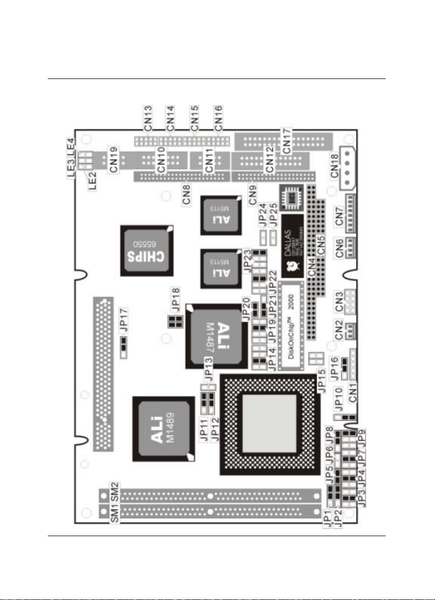
2.3 HS -4000’s Layout
9
Page 12

2.4 Quick Listing of Jumpers
JP1, 2, 3, 4, 5, 7, 8, 9, 10 — for CPU type setting
JP6 — for AMD CPU type selection
JP11, 12 — for Cache size setting
JP13 — CPU clock selection
JP14 — for DiskOnChip™ address setting
JP15 — CPU's Vcore voltage level selection setting
JP16 — CPU's operating voltage selection setting
JP17 — PCI clock setting
JP18 — CPU Clock-in selection
JP19 — WATCH-DOG Time-out period selection
JP20 — PS/2 Mouse IRQ selection
JP21 — WATCH-DOG Active selection
JP22 — RS422/485 Receiver Enable Control
JP23 — RS422/485 Transceiver Enable Control
JP24 — COM4 Enable/Disable setting
2.5 Quick Listing of Connectors
CN1: POWER LED/KEYLOCK
CN2: FAN CON
CN3: FRONT PANEL
CN4: PC104-64
CN5: PC104-40
CN6: POWER CONNECTOR (-12V, -5V)
CN7: KEYBOARD + MOUSE CONNECTOR
CN8: FLAT PANEL PORT
CN9: HDD (IDE) CONNECTOR
CN10: VGA CONNECTOR
CN11: RS422/RS485
CN12: PARALLEL PORT
10
Page 13

CN13: COM1
CN14: COM2
CN15: COM3
CN16: COM4
CN17: FDD CONNECTOR
CN18: POWER CONNECTOR
CN19: ETHERNET CONNECTOR
11
Page 14
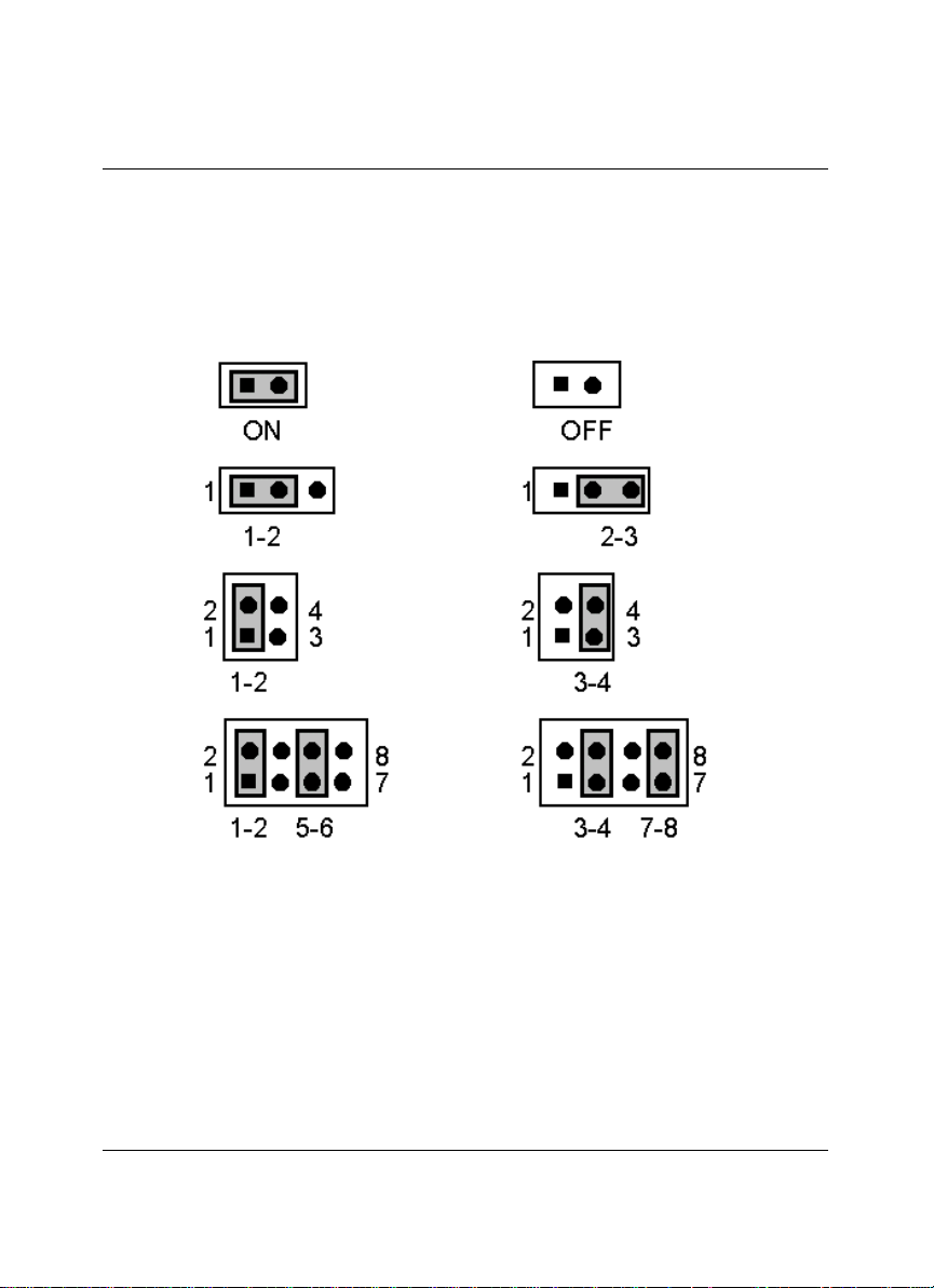
2.6 Jumper Setting Description
A jumper pin-set is ON as a shorted circuit with a plastic cap inserted over two pins.
A jumper pin-set is OFF as a open circuit with a plastic cap inserted over one or no
pin(s) between pins. The below figure 2.2 shows the examples of different jumper
pin-set setting as ON or OFF in this manual.
Figure 2.2
All jumper pin-set already has its default setting with the plastic cap inserted as ON, or
without the plastic cap inserted as OFF. The default setting may reference in this
manual with a " * " symbol in front of the selected item.
12
Page 15

2.7 Setting the CPU of HS -4000
The HS-4000 provides all possibility in jumper setting for wide using all types of 486
series CPU with JP1, JP2, JP3, JP4, JP5, JP7, JP8, JP9 and JP10 setting as following:
?? CPU Clock Setting
CPU JP1 JP2 JP3 JP4 JP5 JP7 JP8 JP9 JP10
1.IntelDX4™ OFF 1-2 3-4 3-4 ON 3-4 2-3 OFF 2-3
2-3 2-3 3-4 3-4 ON 3-4 2-3 5-6 2-3
2-3 2-3 3-4 3-4 ON 3-4 2-3 5-6 2-3
1-2 1-2 5-6 5-6 ON 5-6 2-3 1-2 2-3
OFF 1-2 1-2 OFF OFF OFF 2-3 OFF 2-3
2-3 2-3 3-4 3-4 ON 3-4 2-3 1-3,5-6 2-3
Correspond to different type CPU, it is request to set JP15 and JP16 for match the
CPU operating voltage. Here shows at below of the proper jumper settings for their
respective Vcc.
?? CPU power supply select
JP15 DESCRIPTION
1-2, 3-4 5V
*ALL OFF 3V
JP16 DESCRIPTION
1-2 3.45V
*2-3 3.3V
For AMD type CPU, please set correctly of JP6 as following. For others, please keep
JP6 at OFF setting.
?? AMD CPU type select
JP6 DESCRIPTION
ON AMD DX2
*OFF AMD DX4
2-3 2-3 3-4 3-4 ON 3-4 2-3 1-3,5-6 2-3
13
Page 16

JP18 used to synchronize the CPU clock with the CPU type. Please set the CPU clock
with JP18, JP13 and JP17 jumpers according to the base CPU speed.
?? CPU clock select
JP18 JP13 JP17 DESCRIPTION
OFF, OFF OFF 1-2 25 MHz
*1-2, 3-4 OFF 1-2 33 MHz
OFF, 3-4 ON 2-3 40 MHz
1-2, OFF ON 2-3 50 MHz
2.8 CMOS Data Clear
The JP25 provides a hardware CMOS data clear function with an ON to it. Never clear
CMOS data during power on in case of damage the sensitive electronic components or the board.
?? CMOS Data Clear
JP25 DESCRIPTION
ON Clear Data
*OFF Normal
2.9 Cache Size Select
The HS-4000 design in with a wide ranges Cache Size architectures to meet all different
costs request. The standard specification is 32K x 8.
?? Cache Size select
JP11 JP12 DESCRIPTION
* 2-3 * 2-3 * 32K x 8
1-2 2-3 64K x 8
1-2 1-2 128K x 8
14
Page 17

2.10 System Memory DRAM
The HS-4000 provides a wide range on-board DRAM memory sizes from 1 MB to 16
MB by using 1, 2, 4, 8 or 16MB 72-pin SIMMs (Single In-Line Memory Modules)
with access time should be 70 n-second or faster.
The HS-4000 provides two banks for memory installation by SIMM RAM module
on card. The banks are designated as Bank0 and Bank1. See the figure on section 2.3
for get the identifying the banks. You must use from Bank0 first if install one SIMM
only. If you are using both banks, the memory capacity of both SIMMs should be the
same.
2.11 Watch-Dog Timer
There are three access cycles of Watc h-Dog Timer as Enable, Refresh and Disable. The
Enable cycle should proceed by READ PORT 443H. The Disable cycle should
proceed by READ PORT 043H. A continue Enable cycle after a first Enable cycle
means Refresh.
Once if the Enable cycle activity, a Refresh cycle is request before the time -out period
for restart counting the WDT Timer's period. Otherwise, it will assume that the
program operation is abnormal when the time counting over the period preset of
WDT Timer. A System Reset signal to start again or a NMI cycle to the CPU comes if
over.
The JP21 is using for select the active function of watch-dog timer in disable the
watch-dog timer, or presetting the watch-dog timer activity at the reset trigger, or
presetting the watch-dog timer activity at the NMI trigger.
?? JP21 : Watch-Dog Active Type Setting
JP21 DESCRIPTION
*1-2 System Reset
2-3 Active NMI
OFF disable Watch-dog timer
15
Page 18

?? JP19 : WDT Time - Out Period
PERIOD
1-2 3-4 5-6 7-8
*1 sec OFF OFF ON OFF
2 sec OFF OFF ON ON
10 sec OFF ON OFF OFF
20 sec OFF ON OFF ON
110 sec ON OFF OFF OFF
220 sec ON OFF OFF ON
The Watch-dog timer is disabled after the system Power-On. The watch-dog timer
can be enabled by a Enable cycle with reading the control port (443H), a Refresh cycle
with reading the control port (443H) and a Disable cycle by reading the Watch-dog
timer disable control port (043H). After a Enable cycle of WDT, user must constantly
proceed a Refresh cycle to WDT before its period setting comes ending of every 1, 2,
10, 20, 110 or 120 seconds. If the Refresh cycle does not active before WDT period
cycle, the on board WDT architecture will issue a Reset or NMI cycle to the system.
The Watch-Dog Timer is controlled by two I/O ports.
443H I/O Read The Enable cycle.
443H I/O Read The Refresh cycle.
043H I/O Read The Disable cycle.
The following sample programs showing how to Enable, Disable and Refresh the
Watch-dog timer:
WDT_EN_RF EQU 0443H
WDT_DIS EQU 0043H
WT_Enable PUSH AX ; keep AX DX
PUSH DX
MOV DX,WDT_EN_RF ; enable the watch-dog timer
IN AL,DX
POP DX ; get back AX, DX
POP AX
RET
WT_Rresh PUSH AX ; keep AX, DX
16
Page 19

PUSH DX
MOV DX,WDT_ET_RF ; refresh the watch-dog timer
IN AL,DX
POP DX ; get back AX, DX
POP AX
RET
WT_DISABLE PUSH AX
PUSH DX
MOV DX,WDT_DIS ; disable the watch-dog timer
IN AL,DX
POP DX ; get back AX, DX
POP AX
RET
2.12 VGA Controller
The C&T 655xx family supports a wide variety of monochrome and color
Single-Panel, Single-Drive (SS) and Dual-Panel, Dual Drive (DD) standard and
high-res passive STN and active matrix TFT/MIN LCD, and EL panels. For
monochrome panels, up to 64 gray scales are supported. Up to 4096 different colors
can be displayed on passive STN LCDs and up to 16 M colors on 24-bit active matrix
LCDs.
The HS-4000 uses C&T 65550 chipset. Provides 2.0 mm pitch 44-pin on-board
internal connector for flat panel connection; and a external DB15 analogy R.G.B.
output connector for CRT monitor. By BIOS setup, user may use one of the display
devices or both. Please use at the same resolution when both display. Please contact
with your dealer if connection to a new specification flat panel.
The HS-4000 offers a variety of programmable features to optimize display quality.
Vertical centering and stretching are provided for handling modes with less than 480
lines on 480 - line panels. Horizontal and vertical stretching capabilities are also
available for both text and graphics modes for optimal display of VGA text and
graphics modes on 800x600 and 1024x768 panels.
17
Page 20

2.13 DiskOnChip? Address Setting
The HS-4000 provides a U8 socket for install the DiskOnChip? module.
A JP14 may select the starting memory address of the DiskOnChip?
(D.O.C.) for avoid the mapping area with any other memo ry devices. If you
have another extra memory devices in the system with the same memory,
neither the HS-4000 nor the extra memory devices will function normally.
Please setting both at different memory address mapping.
?? JP14 : DiskOnChip ? Address
PIN NO. Address
*1-2 D000
3-4 D800
5-6 E000
7-8 E800
*) : default setting
The D.O.C. function allows the system in using without FDD nor HDD.
The D.O.C. may formatting as driver C: or driver A:. User may also easily uses
the DOS's commands such as FORMAT, SYS, COPY, XCOPY, DISCOPY
and DISKCOMP etc. This is means that the D.O.C. may uses as driver-A if
the system without FDD-A for ambient application. Please contact with your
supplier for different size D.O.C. module.
18
Page 21

Chapter-3
Connection
This chapter gives all necessary information of the peripheral's connections, switches
and indicators.
3.1 The Floppy Disk Drive Connector
A standard 34-pin header daisy -chain driver connector provides as CN17 with
following pin assignment. Total two FDD drivers may c onnect.
?? CN17 : FDD CONNECTOR
PIN NO. DESCRIPTION PIN NO. DESCRIPTION
1 GROUND 2 REDUCE WRITE
3 GROUND 4 N/C
5 GROUND 6 N/C
7 GROUND 8 INDEX#
9 GROUND 10 MOTOR ENABLE A#
11 GROUND 12 DRIVE SELECT B#
13 GROUND 14 DRIVE SELECT A#
15 GROUND 16 MOTOR ENABLE B#
17 GROUND 18 DIRECTION#
19 GROUND 20 STEP#
21 GROUND 22 WRITE DATA#
23 GROUND 24 WRITE DATA#
25 GROUND 26 TRACK 0#
27 GROUND 28 WRITE PROTECT#
29 GROUND 30 READ DATA#
31 GROUND 32 SIDE 1 SELECT
33 GROUND 34 DISK CHANGE#
19
Page 22

3.2 PCI E-IDE Drive Connector
A standard 40-pin header daisy -chain driver connector provides as CN9 with
following pin assignment. Total two IDE (Integrated Device Electronics) drivers
may connect.
?? CN9(IDE 1) : Primary IDE Connector
PIN NO. DESCRIPTION PIN NO.
1 RESET 2 GROUND
3 DATA 7 4 DATA 8
5 DATA 6 6 DATA 9
7 DATA 5 8 DATA 10
9 DATA 4 10 DATA 11
11 DATA 3 12 DATA 12
13 DATA 2 14 DATA 13
15 DATA 1 16 DATA 14
17 DATA 0 18 DATA 15
19 GROUND 20 N/C
21 N/C 22 GROUND
23 IOW# 24 GROUND
25 IOR# 26 GROUND
27 N/C 28 BALE - DEFAULT
29 N/C 30 GROUND# -DEFAULT
31 INTERRUPT 32 IOCS16#-DEFAULT
33 SA1 34 N/C
35 SA0 36 SA2
37 HDC CS0 38 HDC CS1#
39 HDD ACTIVE 40 GROUND
DESCRIPTION
20
Page 23

3.3 Parallel Port Connector
A standard 26-pin flat cable driver connector provides as CN12 with following pin
assignment for connection to parallel printer.
?? CN12 : Parallel Port Connector
PIN NO.
1 STROBE 2 DATA 0
3 DATA 1 4 DATA 2
5 DATA 3 6 DATA 4
7 DATA 5 8 DATA 6
9 DATA 7 10 ACKNOWLEDGE
11 BUSY 12 PAPER EMPTY
13 PRINTER SELECT 14 AUTO FORM FEED
15 ERROR# 16 INITIALIZE
17 PRINTER SELECT LN# 18 GROUND
19 GROUND 20 GROUND
21 GROUND 22 GROUND
23 GROUND 24 GROUND
25 GROUND 26 GROUND
DESCRIPTION PIN NO.
DESCRIPTION
21
Page 24

3.4 Serial Ports Connectors
The HS-4000's CN13, 14, 15 and 16 headers provides four high speeds NS16C550
compatible UARTs with Read/Receive 16 byte FIFO serial ports. Please see the
following pin assignment. With the delivery package, user may uses the 40-pin COM
cable for plug into CN13, 14, 15 and 16 for get COM1 to COM4 connection. The pin
number inside the ( ) are for 40-pin cable.
?? CN13, 14, 15, 16 : Serial Port 10-pin Headers (COM1~COM4)
COM Port PIN NO. DESCRIPTION PIN NO. DESCRIPTION
1(1) DCD 2(2) DSR
COM 1 3(3) RXD 4(4) RTX
( CN13 )
7(7) DTR 8(8) RI
9(9) GND 10(10) NC
1(11) DCD 2(12) DSR
COM 2 3(13) RXD 4(14) RTX
( CN 14 )
7(17) DTR 8(18) RI
9(19) GND 10(20) NC
1(21) DCD 2(22) DSR
COM 1 3(23) RXD 4(24) RTX
( CN15 )
7(27) DTR 8(28) RI
9(29) GND 10(30) NC
1(31) DCD 2(32) DSR
COM 2 3(33) RXD 4(34) RTX
( CN 16 )
7(37) DTR 8(38) RI
9(39) GND 10(40) NC
5(5) TXD 6(6) CTX
5(15) TXD 6(16) CTX
5(25) TXD 6(26) CTX
5(35) TXD 6(36) CTX
22
Page 25
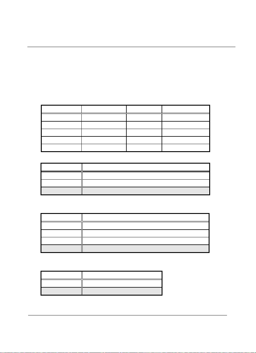
The HS-4000 also provides for user in select to using the COM4 as an RS422/485.
The CN16 for uses as an RS232, the CN11 for uses as an RS422 or RS485.
Please reference to the following for setting the JP22 & JP23 at disable and JP24 at
enable if uses as RS232 at CN16. Or setting the JP22 & JP23 at non-disable and JP24
at disable if uses as RS422 or RS485 at CN11. The default setting is RS-232 at CN16.
?? CN11 : RS422/485
PIN NO. DESCRIPTION PIN NO. DESCRIPTION
1 TX- 2 TX+
3 RX+ 4 RX5 GND 6 RTS7 RTS+ 8 CTS+
9 CTS- 10 NC
?? JP22 : Receiver Enable Control
JP22 DESCRIPTION
1-2 Always Enable
3-4 Enable by writing the REG : 2 EFH BIT1=1
*5-6 Always Disable
*) : default setting
?? JP23 : Transceiver Enable Control
JP23 DESCRIPTION
1-2 Always Enable
3-4 Enable by ”-RTS” signal
5-6 Enable by writing the REG : 2 EFH BIT0=1
*7-8 Always Disable
*) : default setting
?? JP24 : COM4 Selection
JP24 DESCRIPTION
ON As RS-422/485 in CN11
*OFF As RS-232 in CN16
*) : default setting
23
Page 26

3.5 Keyboard & Mouse Connector
The HS-4000 provides a 8-pin header connector CN7 for connection to Keyboard &
Mouse devices.
?? CN7 : 8-pin Header Keyboard Connector
PIN NO. DESCRIPTION PIN NO. DESCRIPTION
1 GND 2 VCC
3 MS-DATA 4 MS-CLK
5 GND 6 VCC
7 KB-DATA 8 KB-CLK
3.6 Power's LED, FAN and Key-Lock Connectors
The CN1 provides both Power's LED and Key-Lock connector as following pin
assignment.
?? CN1 : POWER LED & KEYLOCK
PIN NO. DESCRIPTION
1 POWER LED ANODE
2 KEY
3 GROUND
4 KEYLOCK
5 GROUND
The CN2 provides a FAN connector as following pin assignment.
?? CN2 : FAN CON
PIN NO. DESCRIPTION
1 VCC
2 GROUND
3 +12V
24
Page 27

3.7 DC Main and Aux. Power Connectors
The HS-4000 provides a CN18 connector for the main DC power input connection as
following pin assignment for +5V and +12V.
?? CN18 : POWER CONNECTOR
PIN NO. DESCRIPTION
1 VCC
2 GROUND
3 GROUND
4 +12V
The HS-4000 provides a CN6 connector for the aux. DC power input connection as
following pin assignment for -5V and -12V.
?? CN6 : POWER CONNECTOR
PIN NO. DESCRIPTION
1 -12V
2 GROUND
3 -5V
4 GROUND
3.8 External Front Panel Connector
The HS-4000 has an on-board buzzer. With CN3, it allows user in connection to a
external speaker, IDE’s LED and Reset bottom.
?? CN3 : Front Panel Connector
PIN NO. DESCRIPTION PIN NO. DESCRIPTION
1 IDE-LED 2 VCC
3 SPEAKER 4 GROUND
5 GROUND 6 WATCHDOG CLEAR
7 GROUND 8 RESET
25
Page 28

3.9 PS/2 Mouse IRQ12 Selection Connector
The HS-4000 has an on-bard PS/2 mouse which using IRQ12. If you do not use the
PS/2 mouse and wish to assign IRQ12 for other purposes, you should setting the
JP20 to disconnect PS/2 interrupt from IRQ12.
JP20 SELECTION
OFF No interrupt for PS/2
*ON IRQ12
*) : default setting
3.10 VGA Connector
The HS-4000 has on-board 16-pin external VGA connector.
?? CN10 : VGA Connector
PIN NO. DESCRIPTION PIN NO. DESCRIPTION
1 RED 2 GROUND
3 GREEN 4 GROUND
5 BLUE 6 GROUND
7 GROUND 8 GROUND
9 GROUND 10 HSYNC
11 GROUND 12 VSYNC
13 GROUND 14 NC
15 GROUND 16 NC
26
Page 29

3.11 Fast Ethernet Connector
The Fast Ethernet controller provides with 32-bit performance, PCI bus master
capability, and full compliance with IEEE 802.3 100Base -T specifications.
For 10/100Base -T RJ-45 operation, please connect the network connection by
plugging one end of the cable into the RJ-45 to CN19 Connector.
?? CN19 : Ethernet Connector
PIN NO. DESCRIPTION PIN NO. DESCRIPTION
1 VCC 2 LED 0
3 RX+ 4 RX-
5 LED 1 6 GND
7 LED 2 8 GND
9 TX+ 10 TX-
3.12 PC/104 Bus Connection
The HS-4000’s PC/104 expansion bus provides you in connect to all kind
PC/104 modules connection. The PC/104 bus has already become the industrial
embedded 16-bit PC standard bus, so you can easily install to over thousands of
PC/104 modules from hundreds of venders in the world. The detailed pin
assignment of the PC/104 expansion bus connectors CN4 and CN5 are specified
as following tables:
Note : The PC/104 connector allows to directly plug-in Stack-thru
PC/104 modules without the PC/104 mounting kit.
27
Page 30

?? CN4&CN5 : PC/104 Exp ansion Bus
(CN4 = 64-pin female connector; CN5 = 40-pin female connector.)
Pin CN4 CN4 CN5 CN5
No. RowA RowB RowC RowD
0 -- -- 0V 0V
1 IOCHECK* 0V SBHE*
MEMCS16*
2 SD7 RESETDRV LA23 IOSC16*
3 SD6 +5V LA22 IRQ10
4 SD5 IRQ9 LA21 IRQ11
5 SD4 -5V LA20 IRQ12
6 SD3 DRQ2 LA19 IRQ15
7 SD2 -12V LA18 IRQ14
8 SD1 NOWS* LA17 DACK0*
9 SD0 +12V MEMR* DRQ0
10 IOCHRDY (KEY) MEMW* DACK5*
11 AEN SMEMW* SD8 DRQ5
12 SA19 SMEMR* SD9 DACK6*
13 SA18 IOW* SD10 DRQ6
14 SA17 IOR* SD11 DACK7*
15 SA16 DACK3* SD12 DRQ7
16 SA15 DRQ3 SD13 +5V
17 SA14 DACK1* SD14 MASTER*
18 SA13 DRQ1 SD15 0V
19 SA12 REFRESH* (KEY) 0V
20 SA11 SYSCLK -- -21 SA10 IRQ7 -- -22 SA9 IRQ6 -- -23 SA8 IRQ5 -- -24 SA7 IRQ4 -- -25 SA6 IRQ3 -- -26 SA5 DACK2* -- -27 SA4 TC -- -28 SA3 BALE -- -29 SA2 +5V -- -30 SA1 OSC -- -31 SA0 0V -- -32 0V 0V -- --
28
Page 31

3.13 Flat-Panel Connector
The HS-4000 provides a 44-pin 2.0 mm pitch header connector (CN8) for Flat panel
connection. The information here also provides some pin information samples to
Panel Sharp LM64183P, LM64C35P & LM64C142 and NEC NL8060AC26.
+12V 1 2 +12V
GND 3 4 GND
PVCC 5 6 PVCC
FPVee 7 8 GND
P0 9 10 P1
P2 11 12 P3
P4 13 14 P5
P6 15 16 P7
P8 17 18 P9
P
19 20 P11
10
P
21 22 P13
12
P
23 24 P15
14
P16 25 26 P17
P
27 28 P19
18
P
29 30 P21
20
P22 31 32 P23
GND 33 34 GND
SHFCLK 35 36 FLM
M 37 38 LP
GND 39 40 ENABKL
GND
VCC 43 44 V
41 42 ASHFCLK
CC
29
Page 32

Connections for four standard LCDs
Connections to Sharp LM64183P
(640 x 480 DSTN MONO LCD)
Sharp LM64P83 HS-4000 CN8
Pin Pin name Pin Pin name
CN1-1 S 36 FLM
CN1-2 CP1 38 LP
CN1-3 CP2 35 SHFCLK
CN1-4 DISP 5 +5V
CN1-5 VDD 6 +5V
CN1-6 VSS 3 GND
CN1-7 VEE - -17 V (external power)
CN1-8 DU0 12 P3
CN1-9 DU1 11 P2
CN1-10 DU2 10 P1
CN1-11 DU3 9 P0
CN1-12 DL0 16 P7
CN1-13 DL1 15 P6
CN1-14 DL2 14 P5
CN1-15 DL3 13 P4
30
Page 33

Connections to Sharp LM64C35P
(640 x 480 DSTN Stn Color)
Sharp LM64C35P HS-4000 CN8
Pin Pin name Pin Pin name
CN1-1 DL4 16 P7
CN1-2 Vss 3 GND
CN1-3 DL5 15 P6
CN1-4 YD 36 FLM
CN1-5 DL6 14 P5
CN1-6 LP 38 LP
CN1-7 DL7 13 P4
CN1-8 Vss 4 GND
CN1-9 Vss 8 GND
CN1-10 XCK 35 SLFCHK
CN1-11 DL0 24 P15
CN1-12 Vcon - Contrast Adjust
CN1-13 DL1 23 P14
CN1-14 Vdd 5 +5V
CN1-15 Vss 33 GND
CN1-16 Vdd 6 +5V
CN1-17 DL2 22 P13
CN1-18 DISP 6 +5V
CN1-19 DL3 21 P12
CN1-20 NC - CN1-21 Vss 34 GND
CN1-22 DU3 17 P8
CN1-23 DU4 12 P3
CN1-24 DU2 18 P9
CN1-25 DU5 11 P2
CN1-26 DU1 19 P10
CN1-27 Vss 39 GND
CN1-28 DU0 20 P11
CN1-29 DU6 10 P1
CN1-30 Vss 39 GND
CN1-31 DU7 9 P0
31
Page 34

32
Page 35

Connections to NEC NL8060AC26 (800 x 600 TFT Color)
NEC NL8060AC26 HS-4000 CN8
Pin Pin name Pin Pin name
CN1-1 GND 3 GND
CN1-2 Dot Clock 35 SHFCLK
CN1-3 GND 4 GND
CN1-4 Hsync 38 LP
CN1-5 Hsync 38 FLM
CN1-6 GND 8 GND
CN1-7 GND 8 GND
CN1-8 GND 8 GND
CN1-9 R0 27 P18
CN1-10 R1 28 P19
CN1-11 R2 29 P20
CN1-12 GND 8 GND
CN1-13 R3 30 P21
CN1-14 R4 31 P22
CN1-15 R5 32 P23
CN1-16 GND 39 GND
CN1-17 GND 39 GND
CN1-18 GND 39 GND
CN1-19 G0 19 P10
CN1-20 G1 20 P11
CN1-21 G2 21 P12
CN1-22 GND 39 GND
CN1-23 G3 22 P13
CN1-24 G4 23 P14
CN1-25 G5 24 P15
CN1-26 GND 41 GND
CN1-27 GND 41 GND
CN1-28 GND 41 GND
CN1-29 B0 11 P2
CN1-30 B1 12 P3
CN1-31 B2 13 P4
CN1-32 GND 41 GND
CN1-33 B3 14 P5
CN1-34 B4 15 P6
CN1-35 B5 16 P7
CN1-36 GND 41 GND
CN1-37 DE 37 M
CN1-38 PVcc 43 PVcc
CN1-39 PVcc 44 PVcc
CN1-40 PVcc 5 PVcc
CN1-41 MODE - ---
33
Page 36

Connections to Sharp LM64C142
(640 x 480 DSTN Stn Color)
Sharp LM64C142 HS-4000 CN8
Pin Pin name Pin Pin name
CN1-1 YD 36 FLM
CN1-2 LP 38 LP
CN1-3 XCX 35 SHFCLK
CN1-4 DISP 5 +5V
CN1-5 PVdd 6 +5V
CN1-6 PVss 3 GND
CN1-7 PVee - +27 V (external power)
CN1-8 DU0 20 P11
CN1-9 DU1 19 P10
CN1-10 DU2 18 P9
CN1-11 DU3 17 P8
CN1-12 DU4 12 P3
CN1-13 DU5 11 P2
CN1-14 DU6 10 P1
CN1-15 DU7 9 P0
CN2-1 Vss 4 GND
CN2-2 DL0 24 P15
CN2-3 DL1 23 P14
CN2-4 DL2 22 P13
CN2-5 DL3 21 P12
CN2-6 DL4 16 P7
CN2-7 DL5 15 P6
CN2-8 DL6 14 P5
CN2-9 DL7 13 P4
CN2-10 Vss 8 GND
34
Page 37

Chapter-4
AMI BIOS Setup
For maintain the HS-4000's basic input/output system operating, the HS-4000 is
now using AMI BIOS for the system configuration and operation. The BIOS's setup
program is designed to provide the maximum flexibility in configuring the system by
offering various optional which allowing for select and meet all of the end-user
requirements.
To access AMI BIOS Setup program, press <Del> key when after Power-On-Reset
memory test. The first show out prompt screen is the BIOS setup Main Menu.
User is now may select for Standard CMOS Setup, Advanced COMS Setup, Advanced
Chipset Setup, Power Management Setup, PCI/PnP Setup, Peripheral Setup,
Auto-Detect Hard Disks, Change User Password, Change Supervisor Password,
Change Language Setting, Auto Configuration with Optional Settings and Auto
Configuration with Fail Safe Settings. After any selecting or setting, please choice Save
Settings and Exit or choice Exit Without Saving.
Any miss type in parameters of BIOS setup may cause a screen error display out. You
may load again the default setting of the BIOS by press End key and power-on.
35
Page 38
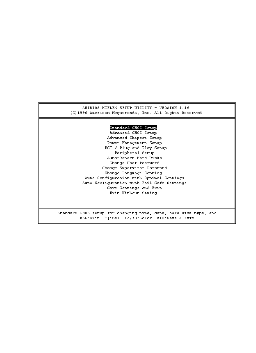
4.1 Main Menu
Once when you enter the AMI BIOS CMOS Setup Utility, the first prompt out screen
is the BIOS's Main Menu. From the Main Menu, the BIOS allow you to select from
several setup functions and two exit choices. Use the arrow keys to select the demand
items and press <Enter> to accept and enter its sub-menu. Press Esc key if
abandoned the selection item.
36
Page 39
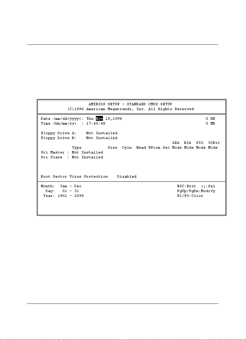
4.2 Standard CMOS Setup
The Standa rd Setup is used for the basic hardware system configuration. The main
function is for Data/Time and Floppy/Hard Disk Drive settings. Please refer to the
following screen for this setup. When the IDE hard disk drive you are using is larger
than 528MB, please set the HDD mode to LBA mode. Please use the IDE Setup
Utility in BIOS SETUP to install the HDD correctly.
37
Page 40
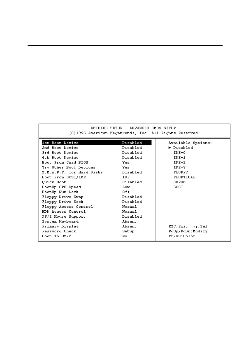
4.3 Advanced CMOS Setup
This advanced setup is designed for the customers to achieve the highest performance
of the HS-4000 board. As for norma l operations, customers don't have to change any
default settings. The default setting is pre-set for most reliable operations. Please refer
to the following screen for the Advanced Setup.
This setup is working for the on-board Multi-I/O Chip (ALI M5113 or UM8669).
These options are used to change the Chipset’s registers. Please carefully change any
default settings to meet your application requirements.
38
Page 41
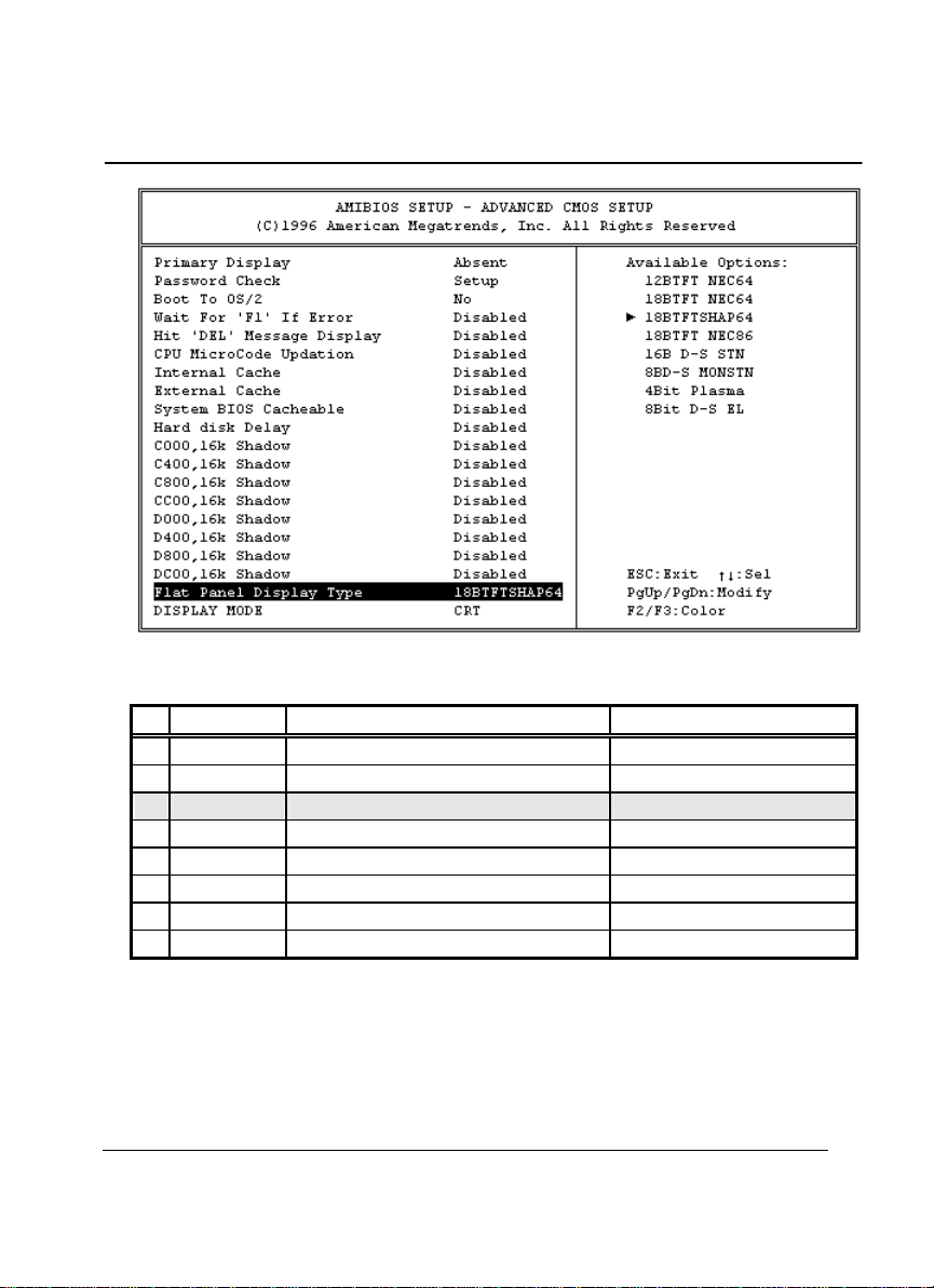
Note: The default Flat Panel Display types currently are:
Default BIOS Panel Types
No Resolution
Data Panel Type
1 640x480 12bit Color TFT NL6448AC30-10 (NEC)
2 640x480 18bit Color TFT NL6448AC33-18 (NEC)
*3 640x480 18bit Color TFT LQ10D41(SHARP)
4 800x600 18bit Color TFT NL8060AC26-11(NEC)
5 640x480 16 bit Dual-Scan Color STN LM64C08P(SHARP)
6 640x480 8 bit Dual-Scan Monochrome STN LM64P11(SHARP)
7 640x480 4 bit Plasma PG640480RM16-3(OKI)
8 640x480 8 bit Dual-Scan EL LJ64H052(SHARP)
*) : default setting
Note: The DISPLAY MODE selects the type of display used for the primary system
monitor.
Display Mode selected LCD means display Flat-Panel only; selected CRT means
display CRT monitor only; selected Both means both display monitor and
Flat-Panel; selected Auto means auto detect LCD or CRT.
39
Page 42
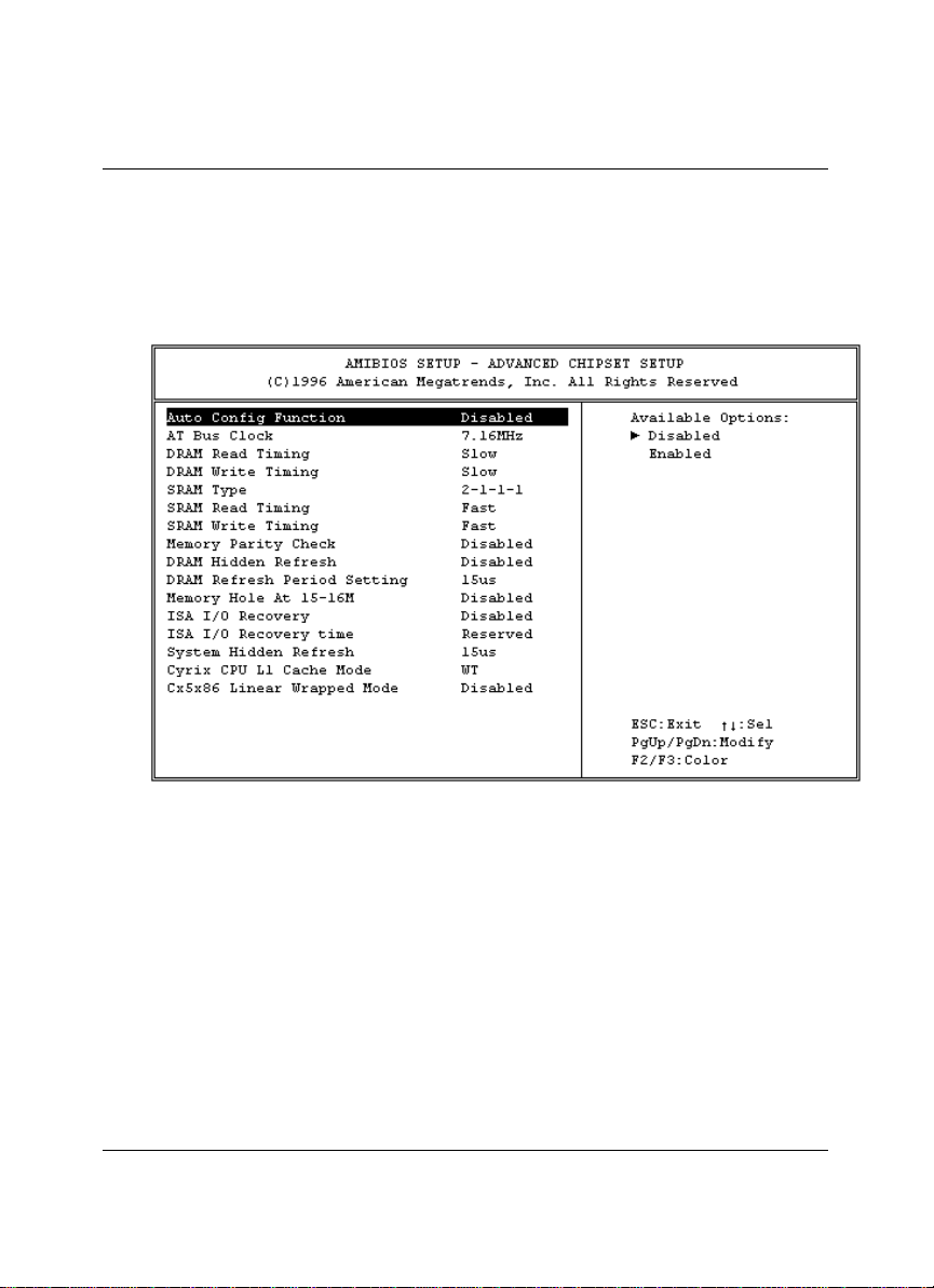
4.4 Advanced Chipset Setup
The advanced chipset setup functions are mostly working for the Chipset ALI
M5113. These options are used to change the Chipset’s registers. Please carefully
change any default settings, otherwise the system could be unstable or may not use.
40
Page 43
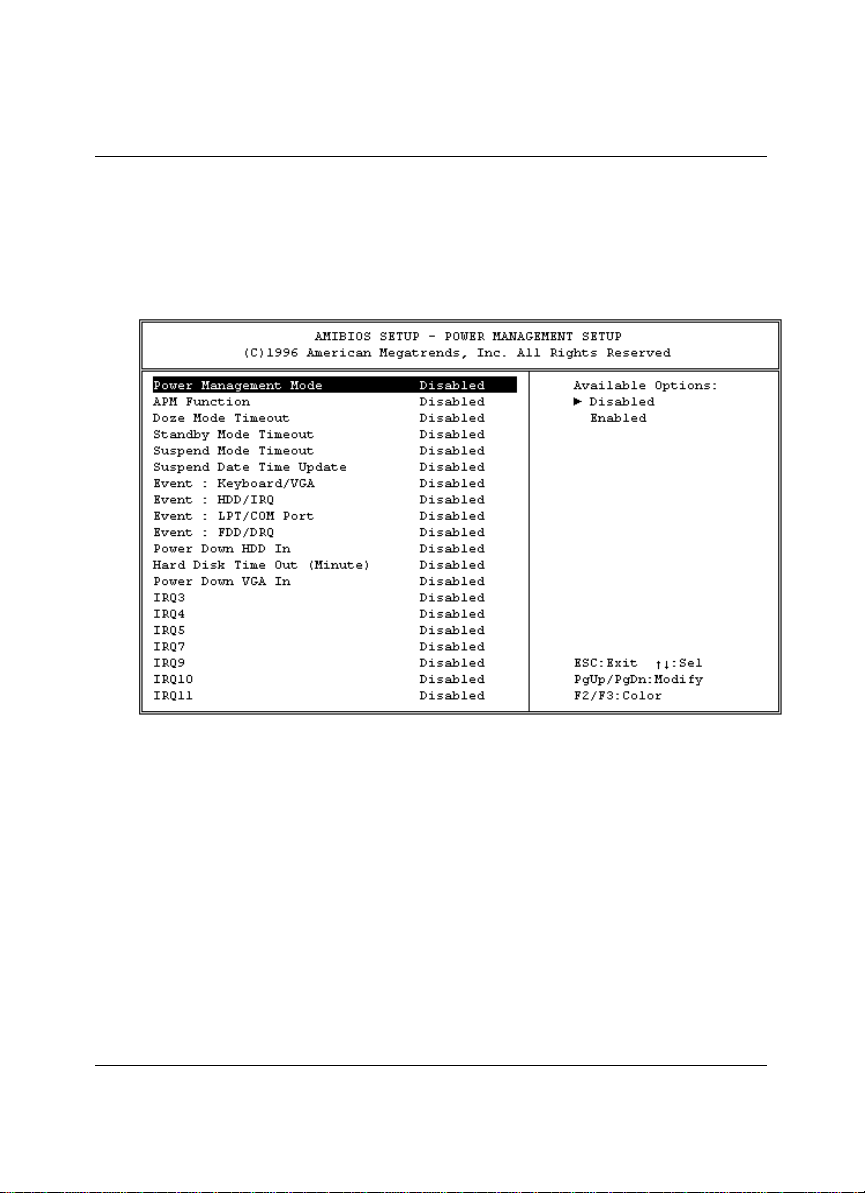
4.5 Power Management Setup
The Power Management Setup allows user to configure the system for save energy in
a most effective way while operating in a manner consistent with his own style of
computer use.
41
Page 44
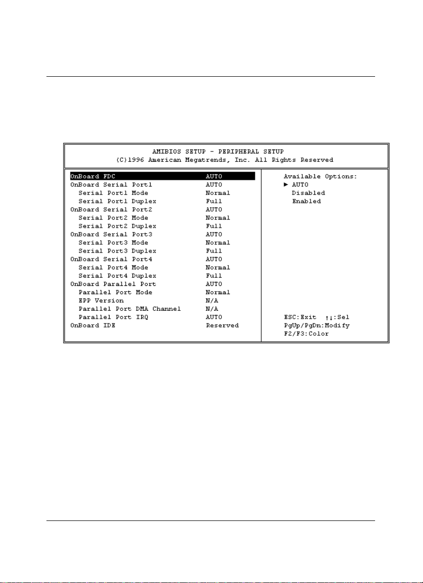
4.6 Peripheral Setup
For completed all input and output devices (i.e. FDD Drivers, IDE Drivers, Serial
Ports, IR and Parallel Port), please refer to the following example.
42
Page 45

Chapter-5
A Brief Browse of 100 base-T LAN
RTL-8139’s Installation Software
The Boser HS-4000 provides an on board 32-bit PCI 100 base -T Ethernet LAN
interface RJ-45 connection for easy using the HS-4000 486 Little All-in-one L/VGA
Industrial Single Board in connection to-with Novell NE2000 compatible LAN
network system.
The HS-4000’s design which is basing on RTL 8139 chipset with provides an RJ-45
100 base -T NE2000 compatible interface. We here provide some information on the
installation for your first reference.
The delivery of the software packages with HS-4000 which including a easy access help
manual by files from. The version of this help manual is 1.00 on dated Jun.19.1997.
Please read all following help manual first before your installation of this LAN
system.
For completed information, please browse at http:\\www.realtek.com.tw
43
Page 46

5.1 Text files list of help documents
TXT\GENERAL\DIRS.TXT
TXT\GENERAL\FILES.TXT
TXT\NETWARE\NETWARE.TXT
TXT\NETWARE\NWODIDOS.TXT
TXT\NETWARE\NW312.TXT
TXT\NETWARE\NW41.TXT
TXT\NETWARE\NW411.TXT
TXT\NETWARE\CLIENT32.TXT
TXT\IBM\IBM.TXT
TXT\IBM\LANSVR23.TXT
TXT\IBM\LANSVR40.TXT
TXT\MS\MS.TXT
TXT\MS\MSCLIENT.TXT
TXT\MS\MSLANMAN.TXT
TXT\MS\MSWFW310.TXT
TXT\MS\MSNT.TXT
TXT\MS\MSWIN95.TXT
TXT\UNIX \UNIX.TXT
TXT\UNIX \SCO4.TXT
TXT\UNIX \SCO5.TXT
TXT\OTHERS\OTHER.TXT
TXT\OTHERS\PACKET.TXT
TXT\OTHERS\LANTAS60.TXT
5.2 Diskette Contents
Files and Dirs Description
VERSION.DOC This document describes some information for this version of
the RTL8139 driver disk;
HELP8139.EXE Help file viewer;
MAINMENU.TXT HELP8139 menu contents. locate it in the same subdirectory
with HELP8139.EXE;
FILEPATH.LST HELP8139 text files path. locate it in the same subdirectory with
HELP8139.EXE;
44
Page 47

RSET8139.EXE RSET8139 program set up the adapter's hardware
configuration and running diagnostics;
OEMSETUP.INF The setup file for NT3.5, NT3.51 & NT4.0;
NETRTP.INF The setup file for Win95 & OSR2;
\TXT This subdirectory includes all text files for instruction to install
various drivers;
\CLIENT32 Subdirectory for Netware Client 32 driver;
\MSCLIENT Subdirectory for Microsoft Network Client for MS-DOS driver;
\MSLANMAN.DOS Subdirectory for DOS NDIS drivers for Microsoft LAN Manager
Versions 1.x and 2.x;
\MSLANMAN.OS2 Subdirectory for OS/2 NDIS drivers for Microsoft LAN Manager
Versions 1.x and 2.x;
\NDIS Subdirectory for OS/2 LAN server & DOS LAN requester driver;
\DOS Subdirectory for IBM DOS LAN requester driver;
\OS2 Subdirectory for IBM OS/2 LAN server driver;
\NWCLIENT Subdirectory for Novell NetWare ODI driver;
\DOS Subdirectory for Novell NetWare DOS/ODI driver;
\NWSERVER Subdirectory for Novell NetWare Drivers;
\312 Subdirectory for Novell NetWare ODI Ver 3.12 server driver;
\41 Subdirectory for Novell NetWare ODI Ver 4.1 server driver;
\411 Subdirectory for Novell NetWare ODI Ver 4.11 server driver;
\RTSPKT Subdirectory for FTP spec -compliant packet driver and Sun
Microsystems PC/NFS Driver;
\SCO
\4.X Subdirectory for SCO UNIX 4.X drivers;
\5.X Subdirectory for SCO UNIX 5.X drivers;
\WFW31 Subdirectory containing Windows for WorkGroup 3.10 driver
files;
\WIN95 Subdirectory containing Win95 & OSR2 driver files;
\WINNT Subdirectory containing Windows NT3.5, NT3.51 &
NT4.0driver files;
5.3 Files on Configuration Disk
ROOT DIRECTORY
VERSION.DOC Describe some information for this version of the
RTL8139 driver disk;
HELP8139.EXE Readme Viewer;
FILEPATH.LST LST file for Readme Viewer;
MAINMENU.TXT TXT file for HELP8139 Mainmenu Title;
RSET8139.EXE RSET8139 program set up the adapter's hardware
configuration and running diagnostics;
45
Page 48

OEMSETUP.INF The setup file for NT3.5, NT3.51 & NT4.0;
NETRTP.INF The setup file for Win95 & OSR2;
\TXT\GENERAL
DIRS.TXT All subdirectory contents about this RTL8139
driver diskette;
FILES.TXT All files abstract in this RTL8139 driver diskette;
\TXT\IBM Text files about IBM NOS Installation Notes :
LANSVR23.TXT
LANSVR40.TXT
\TXT\MS Text files about Microsoft NOS Installation Notes :
MSCLIENT.TXT
MSLANMAN.TXT
MSWFW310.TXT
MSNT.TXT
MSWIN95.TXT
\TXT\NETWARE Text files about Novell NOS Installation Notes :
NWODIDOS.TXT
NW312.TXT
NW41.TXT
NW411.TXT
CLIENT32.TXT
\TXT\OTHERS Text files about Other NOS Installation Notes :
LANTAS60.TXT
PACKET.TXT
\TXT\UNIX Text files about Information on UNIX drivers :
SCO4.TXT
SCO5.TXT
\CLIENT32
RTSSRV.LAN ODI 32-bit driver;
ODIRTL.INF
\MSCLIENT
RTSND.DOS NDIS 2.0 driver;
OEMSETUP.INF Configuration file;
PROTOCOL.INI Protocol.ini stub for LAN Manager install;
\MSLANMAN.DOS\DRIVERS\ETHERNET\RTL8139
RTSND.DOS DOS NDIS 2.01 driver;
PROTOCOL.INI Protocol.ini stub for LAN Manager install;
\MSLANMAN.DOS\DRIVERS\NIF
RTL8139.NIF Standard NIF file for DOS;
\MSLANMAN.OS2\DRIVERS\ETHERNET\RTL8139
RTSND.OS2 OS/2 NDIS 2.0 driver;
PROTOCOL.INI Protocol.ini stub for LAN Manager install;
\MSLANMAN.OS2\DRIVERS\NIF
46
Page 49

RTL8139.NIF Standard NIF file for OS/2;
\NDIS\DOS
RTSND.DOS DOS NDIS 2.0 driver;
RTL8139.NIF Extended NIF file for IBM OS/2;
OEMSETUP.INF Extended NIF file for DOS LAN Requester;
\NDIS\OS2\RTSND.OS2
RTSND.OS2 OS2 NDIS 2.0 driver;
RTL8139.NIF Extended NIF file for IBM OS/2;
\NWCLIENT\DOS
RTSODI.COM ODI driver for DOS;
NET.CFG Sample Net.cfg for ODI;
RTSODI.INS
\NWSERVER\312
RTSSRV.LAN 3.12 Server driver;
MSM31X.NLM
ETHERTSM.NLM
NBI31X.NLM
\NWSERVER\41
RTSSRV.LAN 4.0 Server driver;
ETHERTSM.NLM
MSM.NLM
NBI.NLM
\NWSERVER\411
RTSSRV.LAN 4.11 Server driver;
RTSSRV.LDI
\RTSPKT
RTSPKT.COM Packet Driver;
\SCO\4.X
DRIVER.O SCO UNIX driver;
SETUP
INFO
INIT
MASTER
NODE
RECONF
REMOVE
SPACE.C
SYSTEM
\SCO\5.X
DRIVER.O SCO UNIX driver;
SETUP
MASTER
SYSTEM
47
Page 50

NODE
SPACE.C
SPACE.H
LKCFG
AOF/R8E
\WFW31
RTSND.DOS NDIS 2.0 driver for WfW 3.10;
OEMSETUP.INF Configuration file for WfW 3.11 install;
\WIN95
RTL8139.SYS NDIS 3.1 mini-port driver for Windows 95& OSR2;
\WINNT
RTL8139.SYS NDIS 3.1 mini-port driver for Windows NT3.5, NT3.51
5.4 Installing Novell network drivers to Workstation for
DOS ODI Client
Introduction:
This document describes the procedure to setup the NetWare v3.X , v4.X
workstation driver for REALTEK RTL8139 PCI ethernet adapter.
Location of Driver: \NWCLIENT\DOS\RTSODI.COM
Sample Configuration Files:
STARTNET.BAT:
LSL
RTSODI
IPXODI
NETX or VLM (VLM's for NetWare 4.x )
NET.CFG:
LINK DRIVER RTSODI
SPEED 100 --Specify adapter's speed.
BUSNO NN --where NN is the PCI bus identifier of the PCI bus which
connect to the adapter.
DEVICENO NN --where NN is the specific PCI BIOS device identification
umber of the specified PCI adapter.
[ or you can use "EtherID" to select a specific RTL8139 adapter:
EtherID NNNNNNNNNNNN --Where NNNNNNNNNNNN specify
a RTL8139 adapter's node address. This is only
required when more than one RTL8139 adapters
exist on one system.
]
48
Page 51

FRAME Ethernet_802.2 --Specify frame type
FRAME Ethernet_802.3
FRAME Ethernet_SNAP
FRAME Ethernet_II
NetWare DOS Requester
FIRST NETWORK DRIVE = F
NETWARE PROTOCOL = NDS BIND
PREFERRED SERVER = NW411
Setup Procedures for NetWare 3.11/3.12 Client :
Before you start with the installation process, make sure that the adapter is properly
installed and configured. Make sure that your NetWare workstation is properly installed.
1. Copy RTSODI.COM from the Realtek Driver Diskette subdirectory
A:\NWCLIENT to your harddisk.
2. Create a batch file, or add to your STARTNET.BAT file the commands listed above
under STARTNET.BAT
3. Edit the NET.CFG file that you copied over. Edit the file per your requirements (see
examples above). If there are two frame types listed, whichever frame type is listed first,
that is the one that the driver will load. See above for examples. The NET.CFG file
should be in the same directory with the LSL.COM file.
Setup Procedures for NetWare 4.X Client with vlm:
The installation utility INSTALL.EXE is located on NetWare's "Workstation for DOS"
disk. Run INSTALL.EXE from the Workstation for DOS Disk.
The NetWare Client Install program screen will appear. You must complete each of the
questions. The se options are specific to your needs.
1. Enter the destination directory for the NetWare Client.
(The default directory is C:\NWCLIENT).
2. Gives you the option to automatically update the CONFIG.SYS and the
AUTOEXEC.BAT files or modify them at a later time manually.
3. Do you wish to install support for MS Windows ? (Y/N)
(MS Windows Subdirectory: default C:\WINDOWS)
4. Asks you to select a network driver and provide configuration options. It uses the
specifications you select to create the file NET.CFG. Insert the Realtek drivers disk
when prompted for the driver disk and specify the driver path A:\NWCLIENT\DOS
5. Press <Enter> to install
NOTE:
1. Be sure to add LASTDRIVE=Z to your CONFIG.SYS file for the network mappings
to work properly.
2. When you have multiple RTL8139 Adapters on your system:
Use "BUSNO" and "DEVICENO" KEYWORD in NET.CFG to select which
49
Page 52

adapter to use with your netware client.(or you can use "EtherID")
5.5 Server Driver for NetWare 3.12
Introduction:
This document describes the procedure to install the NetWare v3.12 server driver for
REALTEK RTL8139 Fast Ethernet adapter.
Location of Driver: \NWSERVER\312\RTSSRV.LAN
Installation Procedure:
Before you start with the installation process, make sure tha t the Novell NetWare v3.12
server is properly installed. Similarly, your adapter should also be properly installed in your
server.
1. These files can be obtained from Realtek driver disk subdirectory
A:\NWSERVER\312
NBI31X.NLM
MSM31X.NLM
ETHERTSM.NLM
2. If you can log into the server as a supervisor , copy RTSSRV.LAN relative files from the
Realtek Driver Diskette subdirectory A:\NWSERVER\312 into the NetWare 386
subdirectory SYSTEM of your server. (If some files exists, rename the existing files in
the SYSTEM subdirectory).
3. When the NetWare server prompt appears (indicated by a colon),load your server
driver. Simply type:
: LOAD NBI31X <Enter>
: LOAD RTSSRV <Enter>
or, you can directly load file from Realtek RTL8139 driver disk :
: LOAD A:\NWSERVER\312\NBI31X <Enter>
: LOAD A:\NWSERVER\312\RTSSRV <Enter>
4. Bind IPX to the adapter driver. At the NetWare server prompt, type:
:BIND IPX TO RTSSRV <Enter>
5. After pressing <Enter> the computer prompts you for the Network Number. For
details on how to assign this number, please consult your NetWare Server Installation
Manual.
6. Add the load and bind statements you require to the server's AUTOEXEC.NCF file
so that the LAN driver will load automatically each time the server starts up.
NOTES:
1. Installing Multiple LAN Adapters:
50
Page 53

The keyword "SLOT" is provided for multiple LAN adapters in a single server by the
driver RTSSRV.LAN. So, add "SLOT" in LOAD commands. For example:
LOAD RTSSRV FRAME=Ethernet_802.2 NAME=LAN_A SLOT=1
BIND IPX TO LAN_A NET=11
LOAD RTSSRV FRAME=Ethernet_802.2 NAME=LAN_B SLOT=2
BIND IPX TO LAN_B NET=22
2. The keyword "SPEED" is provided for specifying adapter's speed (10M/100M), add
SPEED in LOAD commands. For example:
LOAD RTSSRV FRAME=Ethernet_802.2 NAME=LAN_A SLOT=1
SPEED=100
BIND IPX TO LAN_A NET=11
3. Installing One LAN adapter with Multiple Frame Types:
When binding multiple frame types to one adapter, enter a LOAD and BIND
statement for each frame type. Each LOAD statement will use a different network
number is required on the bind statement. You need to supply a name on each load
line in order to avoid being prompted for which board to bind IPX to. If you do not
have the name option in the AUTOEXEC.NCF , it will not execute completely
without user intervention. Example:
LOAD RTSSRV FRAME=ETHERNET_802.3 NAME=IEE8023
BIND IPX TO IEE8023 NET=11111
LOAD RTSSRV FRAME=ETHERNET_802.2 NAME=IEE8022
BIND IPX TO LAN8022 NET=22222
If problems occur during the binding process, your screen will prompt you with error
messages. Please refer to your NetWare 386 manual for details on these messages.
5.6 Server Driver for NetWare 4.1
Introduction:
This document describes the procedure to install the NetWare v4.1 server driver for
REALTEK RTL8139 Fast Ethernet adapter.
Location of Driver: \NWSERVER\41\RTSSRV.LAN
Installation Procedure:
Before you start with the installation process, make sure that the Novell NetWare v4.10
server is properly installed. Similarly, your adapter should also be properly installed in your
server.
1. These files can be obtained from Realtek driver disk subdirectory
A:\NWSERVER\41
NBI.NLM
51
Page 54

MSM.NLM
ETHERTSM.NLM
2. If you can log into the server as a ADMIN , copy RTSSRV.LAN relative files from the
Realtek Driver Diskette subdirectory A:\NWSERVER\41 into the NetWare 4.1
subdirectory SYSTEM of your server. (If some files exists, rename the existing files in
the SYSTEM subdirectory).
3. When the NetWare server prompt appears (indicated by a colon),load your server
driver. Simply type:
: LOAD NBI <Enter>
: LOAD RTSSRV <Enter>
or, you can directly load file from Realtek RTL8139 driver disk :
: LOAD A:\NWSERVER\41\NBI <Enter>
: LOAD A:\NWSERVER\41\RTSSRV <Enter>
4. Bind IPX to the adapter driver. At the NetWare server prompt, type:
:BIND IPX TO RTSSRV <Enter>
5. After pressing <Enter> the computer prompts you for the Network Number. For
details on how to assign this number, please consult your NetWare Server Installation
Manual.
6. Add the load and bind statements you require to the server's AUTOEXEC.NCF file
so that the LAN driver will load automatically each time the server starts up.
NOTES:
1. Installing Multiple LAN Adapters:
The keyword "SLOT" is provided for multiple LAN adapters in a single server by the
driver RTSSRV.LAN. So, add "SLOT" in LOAD commands. For example:
LOAD RTSSRV FRAME=Ethernet_802.2 NAME=LAN_A SLOT=1
BIND IPX TO LAN_A NET=11
LOAD RTSSRV FRAME=Ethernet_802.2 NAME=LAN_B SLOT=2
BIND IPX TO LAN_B NET=22
2. The keyword "SPEED" is provided for specifying adapte r's speed (10M/100M),
add SPEED in LOAD commands. For example:
LOAD RTSSRV FRAME=Ethernet_802.2 NAME=LAN_A SLOT=1
SPEED=100
BIND IPX TO LAN_A NET=11
3. Installing One LAN adapter with Multiple Frame Types:
52
Page 55

When binding multiple frame types to one adapter, enter a LOAD and BIND
statement for each frame type. Each LOAD statement will use a different network
number is required on the bind statement. You need to supply a name on each load
line in order to avoid being prompted for which board to bind IPX to. If you do not
have the name option in the AUTOEXEC.NCF , it will not execute completely
without user intervention. Example:
LOAD RTSSRV FRAME=ETHERNET_802.3 NAME=IEE8023
BIND IPX TO IEE8023 NET=11111
LOAD RTSSRV FRAME=ETHERNET_802.2 NAME=IEE8022
BIND IPX TO LAN8022 NET=22222
If problems occur during the binding process, your screen will prompt you with error
messages. Please refer to your NetWare 386 manual for details on these messages.
5.7 Server Driver for NetWare 4.11
Introduction:
This document describes the procedure to install the NetWare v4.11 server driver for
REALTEK RTL8139 Fast Ethernet adapter.
Location of Driver: \NWSERVER\411\RTSSRV.LAN
Installation Procedure :
Before you start with the installation process, make sure that the Novell NetWare v4.11
server is properly installed. Similarly, your adapter should also be properly installed in your
server.
1. Insert the Realtek Driver Diskette into drive A and check the contents of subdirectory
\NWSERVER\411, It should contain the following file :
RTSSRV.LAN: Novell NetWare V4.11 Server Driver
RTSSRV.LDI: Novell NetWare V4.11 Server Driver Installation
Information File
2. At the NetWare prompt (indicated by the Server name), run the INSTALL.NLM
program by typing:
server name: LOAD INSTALL <Enter>
3. Select "Maintenance/Selective Install" and press <Enter>.
4. Select " LAN Driver Options (Configure/Load/...) " and press <Enter>.
5. Press the <Ins> key to specify other drivers to install.
6. Press <F3> and specify the driver path (A:\NWSERVER\411) and press <Enter>.
53
Page 56

7. The RTSSRV.LAN driver should appear in your choice list for the 'Select a LAN
Driver' field. Choose this driver to start the driver loading and binding procedure.
This will allow you to load and bind all 4 frame types supported by NetWare.
8. Add the LOAD and BIND statements you require to the server's AUTOEXEC.NCF
file so that the LAN driver will load automatically each time the server starts up.
Installation Notes:
1. Installing Multiple LAN Adapters:
The keyword "SLOT" is provided for multiple LAN adapters in a single server by the
driver RTSSRV.LAN. So, add EtherID in LOAD commands. For example:
LOAD RTSSRV FRAME=Ethernet_802.2 NAME=LAN_A SLOT=1
BIND IPX TO LAN_A NET=11
LOAD RTSSRV FRAME=Ethernet_802.2 NAME=LAN_B SLOT=2
BIND IPX TO LAN_B NET=22
2. The keyword "SPEED" is provided for specifying adapter's speed (10M/100M),
add SPEED in LOAD commands. For example:
LOAD RTSSRV FRAME=Ethernet_802.2 NAME=LAN_A SLOT=1
SPEED=100
BIND IPX TO LAN_A NET=11
5.8 Client 32 for Windows 95
Introduction:
This document describes the procedure to install the NetWare Client32 driver for
REALTEK RTL8139 Fast Ethernet adapter.
Location of Driver: \CLIENT32\RTSSRV.LAN
Sample Configuration File s:
STARTNET.BAT (Client 32 for DOS will contain):
C:\NOVELL\CLIENT32\NIOS.EXE
LOAD C:\NOVELL\CLIENT32\LSLC32.NLM
LOAD C:\NOVELL\CLIENT32\CMSM.NLM
LOAD C:\NOVELL\CLIENT32\ETHERTSM.NLM
LOAD C:\NOVELL\CLIENT32\RTSSRV.LAN RAME=ETHERNET_802.2
LOAD C:\NOVELL\CLIENT32\RTSSRV.LAN FRAME=Ethernet_802.3
LOAD C:\NOVELL\CLIENT32\RTSSRV.LAN FRAME=Ethernet_II
LOAD C:\NOVELL\CLIENT32\RTSSRV.LAN FRAME=Ethernet_SNAP
54
Page 57

A. Driver Installation Procedures on Clien32 for DOS :
1. If you have completed installed the Netware Client 32 for DOS, all you have to do is to
modify STARTNET.BAT. Please see the sample STARTNET.BAT above. If not,
Please follow the next step 2 - step 7.
2. Run INSTALL.EXE from Netware Client 32 for DOS diskette 1 (or from Netware
4.11 CD). When the product manual appears, mark the "Netware Client 32 for
DOS" item, then press <Enter>.
3. Select "OTHER DRIVERS" item from "32-bit Network Board Drivers" menu,
then press <Enter>.
4. Insert Realtek RTL8139 Driver Diskette, then specify the driver path A: or B:
5. Select "Realtek RTL8139 Fast Ethernet driver", then press <Enter>.
6. Following instructions to complete the Client32 for DOS software installation.
7. Reboot your machine.
Installation Notes:
Installing Multiple LAN Adapters:
The keywor d "SLOT" is provided for multiple LAN adapters in a single server by the
driver RTSSRV.LAN. So, add "SLOT" in LOAD commands. For example:
C:\NOVELL\CLIENT32\NIOS.EXE
LOAD LSLC32.NLM
LOAD CMSM.NLM
LOAD ETHERTSM.NLM
LOAD RTSSRV FRAME=Ethernet_802.2 SLOT=1
LOAD RTSSRV FRAME=Ethernet_802.2 SLOT=2
B. Driver Installation Procedures on Client32 for Windows 3.x :
Refer to Content A. On step 2, mark "Netware Client 32 for DOS" and "Client 32 for
Windows". On step 4, specify the driver path like A:\CLIENT32\RTSSRV.LAN , then
following step 3..7 to complete the installation.
C. Driver Installation Procedures on Client 32 for Windows 95 :
If you have installed the Microsoft Client in your Windows 95 system, you should remove
the adapter object & NDIS 2/3 driver of the RTL8139 adapter from the Windows 95
system. If you have installed previously Realtek's RTL8139 NDIS 2/3 driver, you should
do the following steps before installing the RTL8139 Client 32 driver. ( Note: If you never
pluged Realtek RTL8139 adapter into your PC, Procedure C.1 is not necessary. And you
just start from Procedure C.2)
C.1 Remove the previously installed adapter object & driver of Realtek RTL8139, if any.
1. Under Windows 95 system directory C:\WIN95\INF\, you should delete
NETRTS.INF, *.BIN files.
55
Page 58

2. Click the "My Computer" icon in the Main Program Group.
3. Click the "Control Panel" icon from My Computer window.
4. Click the "System" icon from the Control Panel window.
5. Click the "Device Manager" item.
6. Click the "Networ k adapter" item from System window.
7. Click the "Realtek RTL8139 Fast Ethernet Adapter" icon from System window.
8. Click <Remove> button, then click <OK> button.
9. Close the opened windows.
C.2 Driver Installation on Client 32 for Windows 95 :
1. Plug Realtek's RTL8139 adapter into your PC machine.
2. Turn the power on to bootup the Windows 95.
3. Windows 95 will then prompt the "Realtek RTL8139 Fast Ethernet Adapter" in New
Hardware Found dialog box.
4. Following instructions to complete the installation, Window 95 will ask you the
proper path of the following diskette:
a. Netware Client 32 for Windows 95 Disk
b. Realtek RTL8139 Fast Ethernet Adapter Driver Diskette:
Insert RTL8139 Driver Diskette, then, assign the path to A:\Client32
c. Windows 95 CD-ROM
5.9 Installing IBM network drivers to LAN Server for OS/2
2.3
Introduction:
This document describes the procedure to install NDIS driver on DOS LAN Requester
and OS/2 LAN server 2.0 (or 3.0) for Realtek RTL8139 Fast PCI ethernet adapter.
Location of Driver: \NDIS\DOS\RTSND.DOS (for DOS LAN Requester)
\NDIS\OS2\RTSND.OS2 (for OS/2 LAN Server)
Installing driver procedure on DOS LAN Requester :
1. Insert the IBM LAN Support Program (LSP) Version 1.30 (or 1.31) Diskette into your
floppy drive A: .
2. Type A:\dxmaid and press <Enter> .
3. The screen will display the IBM logo. Press <Enter> twice until the "Environment
Information" appears on screen.
4. Responds to the screen prompts, specifying the following values for each field, use the
<Space Bar> to toggle between choices:
Configuration for this computer? Yes
56
Page 59

Use existing configuration information? Yes
Do you have adapter option diskettes? Yes
Are you configuring for two adapters? No
Do you need 802.2 interface support? Yes
Source for LSP A:\
Target for new configuration C:\LSP
Make sure that the values given above are correct, then press <Enter> to store your
choices.
5. Insert the Realtek RTL8139 driver diskette in floppy A, and specify your path name
A:\NDIS\DOS, then press ENTER.
6. Follow screen instructions to complete the process. Simply pressing <Enter> for
each screen display will select the default options. Press <Enter> until you reach the
display prompting you to insert the LSP diskette.
7. Insert the LSP diskette as prompted. Press <Enter> to acknowledge completion of
the action.
8. A screen showing the current configuration detected will be displayed. It should
show the Realtek RTL8139 adapter and the protocols already selected (i.e., "IBM
IEEE 802.2" and "IBM OS/2 NETBIOS").
9. Press <F4>. to save the new configuration. This completes the LSP installation.
10. Save the configuration and reboot your computer.
11. Insert the DOS LAN Requester Install Diskette 1 into your floppy drive.
12. Type A:\INSTALL <Enter>
13. The IBM logo will again appear on the screen. Press <Enter> to move on to the next
screen.
14. Follow screen instructions, pressing <Enter> to move from screen-to-screen until
you are prompted to indicate the path name of the DOS LAN Requester directory
(C:\DOSLAN ).
15. Specify the path name (C:\DOSLAN is the default) for the DOS LAN Requester
directory . Then press <Enter> to continue.
16. The program will ask you for the services that you require.
17. Highlight the appropriate option. Select either "Send messages" or "Send, View, Edit,
and Log message" option. (Normally, second option "Send, View, Edit and Log
message" is selected).
18. Specify the PC's ID and domain ID.
19. Follow screen prompts to complete the installation.
Installing driver procedure on OS/2 LAN Server 2.0/3.0 :
Before you start with the installation process, make sure that OS/2 LAN Server is
properly installed. Similarly, your adapter should also be properly installed in your server.
1. Copy RTSND.OS2 and RTL8139.NIF files from your Driver diskette (\NDIS\OS2)
to C:\IBMCOM\MACS.
2. Click the OS/2 LAN Service icon.
57
Page 60

3. Select "Installation and configuration". The IBM logo should appear onscreen.
4. Click <OK>.
5. Select <Advance> and press <Enter>.
6. Select "Install or Configuration this Workstation."
7. Select server type, adding a server or domain controller. The "install or remove"
selections should appear.
8. Select "Configure a component."
10. Click the "Configure" button.
11. Select "Configure workstation."
12. Select "RTL8139 Fast ethernet adapter" when prompted to identify you Network
Adapter. Then click the <Add> button.
13. Select IBM NETBIOS from the list and click the <Add> button.
14. Select <OK> to confirm all selections.
15. Follow screen instructions to complete the process, selecting <OK> to accept default
selections.
16. Continue pressing <OK> until your screen prompts you to backup old
CONFIG.SYS and AUTOEXEC.BAT and create a new CONFIG.SYS and
AUTOEXEC.BAT. Also select <OK> to confirm this.
17. Installation is complete now. Reset your PC by turning it off and on.
Note:
1. The DOS version must be bellow DOS 5.0 when install DOS LAN requester
into your system.
2. Sample protocol.ini:
[RTL8139]
DriverName=RTSND$
EtherID=@52544C111111 ;This keyword is used to designate to a RTL8139
;adapter by assigning it's ethernet ID
;when more than one adapters exist on one
; system.
BusNo=@00 ;This keyword is used to designate a RTL8139
;adapter by assigning it's PCI bus number
;when more than one adapters exist on one
; system.(must be used with 'DeviceNo' keyword)
DeviceNo=@0A ;This keyword is used to designate a RTL8139
;adapter by assigning it's PCI Device number
;when more than one adapters exist on one
; system.(must be used with 'BusNo' keyword)
58
Page 61

Speed= 100/10 ;This keyword is used to force RTL8139 adapter
;to speed 10M or 100M mode. If not present,
;the driver will auto-detect the speed.
5.10 LAN Server for OS/2 4.0
[1]. Introduction:
This document describes the procedure to install NDIS driver on DOS LAN Requester
and OS/2 LAN server 4.0 for Realtek RTL8139 ethernet adapter.
Location of Driver: \NDIS\DOS\RTSND.DOS (for DOS LAN Services)
\NDIS\OS2\RTSND.OS2 (for OS/2 LAN Server)
[2]. Installing driver procedure on DOS LAN Requester :
Before you start with the installation process, make sure that DOS LAN Services is
properly installed. Similarly, your adapter should also be properly installed in your client
PC.
1. Copy RTSND.DOS from your Driver diskette (A:\NDIS\DOS) to DOS LAN
Services subdirectory C:\DLS .
2. Under DOS LAN Requester subdirectory C:\DLS, run INSTALL
3. The screen display some description. If it's correct, move highlight to "The listed
options are correct" item ,then press ENTER.
4. Move highlight to "Network Card", then press ENTER.
5. Select "Change driver for network card." item, then press ENTER.
6. Select "Network card not shown in list below..", then press ENTER.
7. Insert the Realtek RTL8139 driver diskette in floppy A, and specify your pathname
A:\NDIS\DOS,then press ENTER.
8. Realtek 8139 driver is now installed on your computer, reboot your computer.
[3]. Installing driver procedure on OS/2 LAN Server 4.0:
Before you start with the installation process, make sure that OS/2 LAN Server is
properly installed. Similarly, your adapter should also be properly installed in your server.
1. In OS/2 window, Click the "MPTS" icon.
2. The screen will display the IBM Log, press "OK".
3. Select "Install" button.
4. Insert the REALTEK RTL8139 driver diskette, specify the driver path A:\NDIS\OS2
and press <Enter>.
5. When complete above step to load RTSND.OS2 into OS/2 system, then configure
your system.
6. The same step as step 3, select "Configure" button.
59
Page 62

7. The screen will display "Configure" dialog box and select "LAN adapters and
protocols" then press "configure" button.
8. The screen will display "LAPS Configuration" dialog box, move highlight to
"RTL8139 Fast PCI Ethernet Adapter" item in "Network Adapter" window, and select
"NetBios" protocol. Press "OK".
9. Installation is complete now. Reset your PC by turning it off and on.
[4]. Installing Multiple LAN Adapters:
1. follow [3]. 1-9 and add tow RTL8139 Adapter driver
2. in IBM Lan Services icon, OS/2 Lan Sercices Installation /Configuration
Select your the server of the insatlled,[OK].
Do you want to re-install this version.[No].
Installing to card driver [OK]
Configure a component. [OK]
Lan Services Adapters. [OK]
Configure. [OK]
Two Adapter [V]. OK
[5]. A sample PROTOCOL.INI file:
[RTL8139]
DriverName=RTSND$
EtherID=@52544C111111 ;This keyword is used to desinate a RTL8139
;adapter by assigning it's ethernet ID
;when more than one adapters exist on one
;system.
BusNo=@00 ;This keyword is used to designate a RTL8139
;adapter by assigning it's PCI bus number
;when more than one adapters exist on one
; system.(must be used with 'DeviceNo' keyword)
DviceNo=@0A ;This keyword is used to designate a RTL8139
;adapter by assigning it's PCI Device number
;when more than one adapters exist on one
; system.(must be used with 'BusNo' keyword)
Speed= 100/10 ;This keyword is used to force RTL8139 adapter
;to speed 10M or 100M mode. If not present,
;the driver will auto-detect the speed.
5.11 Installing Microsoft network drivers to Microsoft
60
Page 63

Network Client for DOS
Introduction:
This document describes the procedure to setup the Microsoft Network Client for DOS
driver on REALTEK RTL8139 Fast PCI adapter.
Location of Driver: \MSCLIENT\RTSND.DOS
Sample Configuration Files:
Ex1: [PROTOCOL.INI] (install creates this file)
[network.setup]
version=0x3110
netcard=RTL8139,1,RTL8139,1
transport=ms$ndishlp,MS$NDISHLP
transport=ms$netbeui,MS$NETBEUI
lana0=RTL8139,1,ms$netbeui
lana1=RTL8139,1,ms$ndishlp
[protman]
DriverName=PROTMAN$
PRIORITY=MS$NDISHLP
[MS$NDISHLP]
DriverName=ndishlp$
BINDINGS=RTL8139
[MS$NETBEUI]
DriverName=netbeui$
SESSIONS=10
NCBS=12
BINDINGS=RTL8139
LANABASE=0
[RTL8139]
; RTL8139 RPOTOCOL.INI SAMPLE
DriverName=RTSND$
EtherID=@52544C111111 ;This keyword is used to designate a RTL8139
;adapter by assigning its ethernet ID
;when more than one adapters exist on one
; system.
BusNo=@00 ;This keyword is used to designate a RTL8139
;adapter by assigning it's PCI bus number
61
Page 64

;when more than one adapters exist on one
; system.(must be used with 'DeviceNo' keyword)
DeviceNo=@0A ;This keyword is used to designate a RTL8139
;adapter by assigning it's PCI Device number
;when more than one adapters exist on one
; system.(must be used with 'BusNo' keyword)
Speed = 100/10 ;This keyword is used to force RTL8139 adapter
;to speed 10M or 100M mode. If not present,
;the driver will auto-detect the speed.
Installation Procedure :
Before you start with the installation procedure, make sure that the adapter is properly
installed and configured. Similarly, Make sure that your Microsoft Network Client is
properly installed.
(If not, The installation utility SETUP.EXE is located on Microsoft Network Client v3.0
for MS-DOS Disk. Run SETUP.EXE from Disk and the SETUP program screen will
appear, and You must complete each of the questions. These options are specific to your
needs. The installation procedure will transfer files to a specific directory on the client and
modify existing configuration files to fit your specific needs.)
1. Change to the Microsoft Network Client subdirectory, and run SETUP.EXE
2. The screen will display some information. Press <Enter> .
3. Responds to the screen prompts, selecting "Change Network Configuration", then
press <Enter>.
4. Move the highlight to "Add Adapter", press <Enter>.
5. Select "Network adapter not shown on list below ...".
6. Insert the Realtek RTL8139 driver diskette in floppy A, and specify your pathname
A:\MSCLIENT ,then press <Enter>.
7. Follow screen instructions to complete the pr ocess. Simply pressing <Enter> for
each screen display will select the default options. Press <Enter> until you reach the
display prompting you to reboot your system.
Installing Multiple LAN Adapters:
There are two different method to complete it:
To Follow Installation Procedure and add two adapter,
(a) Under DOS mode, you can modify the EtherID or BusNo+DeviceNo keyword
field in file C:\MSCLIENT\PROTOCOL.INI.
(b)Or you can also use the SETUP program and follow above setup procedure step 4,but
move the highlight to "Change Setting, then press <Enter>, the screen will prompt
you to fill EtherID value .
62
Page 65

5.12 LAN Manager Workstation / Server
Introduction:
This document describes the procedure to setup LAN Manager 2.1 Workstation/Server
driver for REALTEK RTL8139 Fast PCI ethernet adapter.
Location of Driver:
(DOS) \MSLANMAN.DOS\DRIVERS\ETHERNET\RTL8139\RTSND.DOS
(OS/2)\MSLANMAN.OS2\DRIVERS\ETHERNET\RTL8139\RTSND.OS2
Sample Configuration Files:
CONFIG.SYS (for DOS will contain):
DEVICE=C:\LANMAN.DOS\DRIVERS\PROTMAN\PROTMAN.DOS
/I:C:\LANMAN.DOS
DEVICE=C:\LANMAN.DOS\DRIVERS\ETHERNET\RTL8139\RTSND.DOS
CONFIG.SYS (for OS/2 will contain):
DEVICE=C:\LANMAN.OS2\DRIVERS\PROTMAN\PROTMAN.OS2
\I:C:\LANMAN.OS2
DEVICE=C:\LANMAN.OS2\DRIVERS\ETHERNET\RTL8139\RTSND.OS2
PROTOCOL.INI (will contain):
[RTL8139]
; RTL8139 RPOTOCOL.INI SAMPLE
DriverName=RTSND$
EtherID=@52544C111111 ;This keyword is used to designate a RTL8139
;adapter by assigning its ethernet ID
;when more than one adapters exist on one
; system.
BusNo=@00 ;This keyword is used to designate a RTL8139
;adapter by assigning it's PCI bus number
;when more than one adapters exist on one
; system.(must be used with 'DeviceNo' keyword)
DeviceNo=@0A ;This keyword is used to designate a RTL8139
;adapter by assigning it's PCI Device number
;when more than one adapters exist on one
; system.(must be used with 'BusNo' keyword)
63
Page 66

Speed= 100/10 ;This keyword is used to force RTL8139 adapter
;to speed 10M or 100M mode. If not present,
;the driver will auto-detect the speed.
Setup driver procedures on LAN Manager workstation/server :
Before you start with the installation process, make sure that the adapter is properly
installed and configured. Make sure your Microsoft LAN Manager is properly installed.
1. Run the appropriate Microsoft Lan Manager SETUP for computer you
are setting up.(DOS, OS/2 or OS/2 Server). Select "Configuration"
item ,(the Realtek driver isn't included on the Lan Manager disk)
and insert the Realtek RTL8139 driver disk, select the Realtek
driver and follow the directions.
2. When completed, reboot your computer.
Installing Multiple LAN Adapters:
To Follow Setup driver Procedure and add two adapter,
Under DOS mode, you can modify the EtherID or BusNo+DeviceNo Keyword field in
file C:\LANMAN\PROTOCOL.INI.
5.13 Windows for Workgroups v3.0
Introduction:
This document describes the procedure to install Microsoft Windows for Workgroups
v3.10 driver for REALTEK RTL8139 Fast ethernet adapter.
Location of Driver: \WFW31\RTSND.DOS
Sample Configuration Files:
CONFIG.SYS (install will add these lines)
DEVICE=C:\WINDOWS\PROTMAN.DOS /I:C:\WINDOWS
DEVICE=C:\WINDOWS\RTSND.DOS
*** DEVICE=C:\WINDOWS\MSIPX.SYS (Added if running NetWare)
DEVICE=C:\WINDOWS\WORKGRP.SYS
LASTDRIVE=P
PROTOCOL.INI (install creates this file)
[network.setup]
version=0x3100
netcard=RTL8139,1,RTL8139
64
Page 67

transport=ms$netbeui,MS$NETBEUI
*** transport=ms$ipx,MS$IPX (Added if running NetWare)
lana0=RTL8139,1,ms$netbeui
*** lana0=RTL8139,1,ms$ipx (Added if running NetWare)
[protman]
DriverName=PROTMAN$
PRIORITY=MS$NETBEUI
[RTL8139]
; RTL8139 RPOTOCOL.INI SAMPLE
DriverName=RTSND$
EtherID=@52544C111111 ;This keyword is used to designa te a RTL8139
;adapter by assigning its ethernet ID
;when more than one adapters exist on one
; system.
BusNo=@00 ;This keyword is used to designate a RTL8139
;adapter by assigning it's PCI bus number
;when more than one adapters exist on one
; system.(must be used with 'DeviceNo' keyword)
DeviceNo=@0A ;This keyword is used to designate a RTL8139
;adapter by assigning it's PCI Device number
;when more than one adapters exist on one
; system.(must be used with 'BusNo' keyword)
Speed= 100/10 ;This keyword is used to force RTL8139 adapter
;to speed 10M or 100M mode. If not present,
;the driver will auto-detect the speed.
[MS$NETBEUI]
DriverName=netbeui$
SESSIONS=10
NCBS=32
BINDINGS=RTL8139
LANABASE=0
*** [MS$IPX] (Added if running NetWare)
*** Drivername=IPX$ (Added if running NetWare)
*** MediaType=Novell/Ethernet (Added if running NetWare)
*** Bindings=RTL8139 (Added if running NetWare)
65
Page 68

AUTOEXEC.BAT
C:\WINDOWS\NET START
*** C:\WINDOWS\MSIPX (Added if running NetWare)
*** C:\WINDOWS\NETX (Added if running NetWare)
New Windows for Workgroups Installation:
1. When installing Windows for Workgroups, you are prompted for a network driver.
Select the "Unlisted or Updated Network Driver".
2. Insert the REALTEK adapter driver disk containing OEMSETUP.INF and
RTSND.DOS files.
3. Specify the directory for the driver (A:\WFW31) and select the Adapter driver.
4. Select Advanced options, and make sure the parameters match the card settings. Check
keyword "EtherID", which is provided by RTSND.DOS. The installation program
copies the necessary files and creates PROTOCOL.INI for use with the adapter.
5. Continue the installation per Windows for Workgroups instructions.
Existing Windows for Workgroups Installation:
1. Select the "Control Panel" icon in the Main Group.
2. Select the "Network" icon.
3. Select the "Adapters" button.
4. Select the Add option.
5. Select "Unlisted or Updated Network Adapter"
6. Insert the adapter driver disk with OEMSETUP.INF and RTSND.DOS and
specify the path A:\WFW31.
7. Select the REALTEK adapter driver.
8. The installation program copies the necessary files and
creates PROTOCOL.INI for use with the adapter.
9. Select "Close" and when prompted, restart computer for changes to
take affect and complete the installation.
NOTE: You must have a terminated cable attached to the adapter when you start
Windows for Workgroups. If you don't, Windows for Workgroups hangs.
TO ADD NETWARE:
1. Select the "Control Panel" icon in the Main Group.
2. Select the "Network" icon.
3. Select the "Networks" button.
4. Select "Novell Netware" and select the add button.
5. Select "OK" and close the Network icon.
6. Select reboot computer and restart Windows.
Installing Multiple LAN Adapters:
There are two different method to complete it:
66
Page 69

(a) Under DOS mode, you can modify the EtherID or BusNo+DeviceNo keyword
field in file C:\WFW31\PROTOCOL.INI.
(b) Or you can enter Windows for WorkGroup and follow above setup procedure step
2,then click on "Setup.." button, select "Advanced...",fill EtherID in Value item. Last
step to select OK and close NETWORK SETUP.
5.14 Windows NT 3.5, 3.51, & 4.0
Introduction:
This document describes the procedure to install Windows NT v3.5, v3.51 & v4.0 driver
for Realtek RTL8139 PCI Fast Ethernet adapter.
Location of Driver: \WINNT\RTL8139.SYS
Installing driver procedure on Microsoft Windows NT :
When you are in Windows NT :
1. In the Main group of NT, select the "Control Panel" icon.
2. In the Control Panel window, choose the "Network" icon.
3. In the Network Settings dialog box, choose the "Add Adapter" button. The Add
Network Adapter dialog box appears.
4. In the list of network cards, select "<other> Requires disk from manufacturer", and
then press <Enter> button.
5. Insert the Realtek driver disk in drive A, enter drive and pathname A:\ which is the
path where the setup file OEMSETUP.INF is located, and then choose the OK
button.
6. The screen will appear "Select Line Speed" dialog box which is provide by
RTL8139.SYS driver. The default value is "auto" so that the RTL8139 PCI Fast
Ethernet adapter and its driver RTL8139.SYS will auto-detect the line speed, 10 Mb or
100Mb, while the RTL8139.SYS is loading. The other values, "10" or "100", are only
used when you want to forced RTL8139 PCI Fast Ethernet adapter to 10Mb or
100Mb.
7. The screen will appear "Input EthernetID" dialog box which is provide by
RTL8139.SYS driver. This option is only required when you have more than one
Realtek RTL8139 PCI Fast Ethernet adapters on this computer. Select "SKIP" if only
one adapter is installed on this computer.
8. "Bus Location" display in next screen. Your machine contains more than one
hardware bus, please select the Bus Type and Bus number on which your ne twork
adapter card is installed.
9. NT will then perform the binding process. If any additional network software options
were installed, you may be prompted for specific information for these packages.
67
Page 70

10. Restarting your system you will acquire networ k service.
NOTES:
Installing Multiple LAN Adapters:
Enter Windows NT and follow above setup procedure step 2,in the "Network Settings"
dialog box, choose the "Configure.." button. The "Input Ethernet ID" dialog box
appears and input adapter's Ethernet ID. Last step to select OK and close NETWORK
SETUP. Select SKIP if only one adapter is installed on this computer.
5.15 Windows 95 & OSR2
Introduction:
This document describes the procedure to install Windows 95 and OSR2 driver for
Realtek RTL8139 PCI Fast Ethernet adapter.
Location of Driver: \WIN95\RTL8139.SYS
Installing driver procedure on Microsoft Windows 95 :
Before you start with the installation process, make sure that your adapter should be
properly installed in your PCI bus slot. Executing Windows 95, it will auto-detect your
system configuration and find the adapter hardware. ( If Win95 does not prompt that it
detects the PCI Ethernet adapter, there must be something wrong with
the RTL8139 PCI Fast Ethernet adapter or your system environment.)
1. Ask you to select which driver you want to install, select "Driver from disk provided by
hardware manufacturer".
2. Insert the Realtek RTL8139 driver disk into drive A and specify the setup file pathname
A:\ .
3. Windows 95 will appear some messages to insert Windows 95 system disk to
complete setup step.
4. Windows 95 will finish the other installation procedure automatically, then you
restart the system.
5.16 Installing UNIX network drivers to SCO UNIX 4.x
Introduction:
This document describe s the procedure to install the SCO UNIX driver for REALTEK
RTF8139 PCI fast ethernet adapter.
Location of Driver: \SCO\4.X\DRIVER.O
The following files will be used in this installation:
DRIVER.O : RTFSCO Driver Program
68
Page 71

INSTALL : Transfer dos forma t to unix format setup program
INFO : Used by netconfig
INIT : Used by netconfig
MASTER : Used by netconfig
NODE : Used by netconfig
RECONF : Used by netconfig
REMOVE : Used by netconfig
SPACE.C : Used by netconfig
SYSTEM : Used by netconfig
Installing driver procedure on SCO UNIX :
Before you start with the installation process, make sure that the SCO UNIX system is
properly installed. Similarly, your adapter should also be properly installed in your
machine.
1. Login as root user. (On maintena nce mode)
2. If you own installation Diskette in DOS format :
Put RTL SCO UNIX Driver diskette to floppy A: and use doscp command to copy the
file "install" for installing RTF SCO UNIX PCI Driver into UNIX's directories as
following :
# cd /
# doscp A:/sco/install /install
# chmod +x /install
# ./install
Then, the install program will ask you for path of the files, you can key in:
a:/sco/4.x
or
b:/sco/4.x
3. Use netconfig utility, available options :
# netconfig
The screen will display the following messages, and Select item (1) to Add a chain :
1) Add a chain
2) Remove a chain
3) Reconfigure an element in a chain
4) Quit
4. After the above option completed, the screen display next option messages :
Select item (4) : sco_tcp SCO TCP/IP for UNIX
5. When the user completed the above option, then various adapter drivers in SCO
UNIX occur and select "RTL PCI Family Fast Ethernet Driver board 0" item.
6. Add chain sco_tcp -> r7e0 (y/n), TYPE 'y'
7. Type in the line speed parameter, or just key in "ENTER" for auto detecting line
speed.
Key in speed parameter Explanation
69
Page 72

100 100 Mbps
10 10 Mbps
auto or “ENTER” auto detect
8. Enter the internet Address of this interface, for example : 192.9.9.1
9. Enter the netmask for this interface (default 255.255.255.0).
10. Does the interface use a broadcast address of all 1's (y/n),
default : y
11. Enter the boardcast address for this interface,
default : xxx.xx.x.255 press ENTER
12. Are these values correct ? (y/n) TYPE 'y'
13. Pseudo ttys are currently configured, do you want to:
1) Add Pseudo ttys
2) Remove Pseudo ttys
Select an option or enter q to quit [q] TYPE 'q'
14. Available options:
1) Add a chain
2) Remove a chain
3) Reconfigure a element in a chain
q Quit
Select option: q
15. Do you want to relink to kernel now ? y
16. Do you want this kernel to boot by default (y/n) y
17. Do you want the kernel environment rebuilt (y/n) y
18. Reboot unix
# shutdown -g0
5.17 SCO UNIX 5.x
Introduction:
This document describes the procedure to install the SCO UNIX driver for REALTEK
RTL8139 PCI ethernet adapter.
Location of Driver: \SCO\5.X\DRIVER.O
The following files will be used in this installation:
driver.o : RTL 8139 MDI Driver Program
install : Transfer dos format to unix format setup program
Master : Used by netconfig
System : Used by netconfig
Node : Used by netconfig
Space.c : Used by netconfig
Space.h : Used by netconfig
70
Page 73

lkcfg : Used by netconfig
AOF/r8e : Used by netconfig
Installing driver procedure on SCO UNIX :
Before you start with the installation process, make sure that the SCO UNIX system is
properly installed. Similarly, your adapter should also be properly installed in your
machine.
1. Installation Diskette in DOS format.
Put RTL SCO UNIX Driver diskette to floppy A: and use doscp command to copy
RTL SCO UNIX PCI Driver into UNIX's directories.
# cd /
# doscp A:install /install
# chmod +x /install
# ./install
Then, the install program will ask you for path of the files, you can key in:
a:/sco/5.x
or b:/sco/5.x
2. Use netconfig utility
Available options:
# netconfig
3. To add adapters, select "Add New Lan Adapter" from "Hardware".
4. Select the line speed from the menu:
(1) 100 Mbps (2) 10 Mbps (3) auto detect
5. Add Protocol to select SCO TCP/IP.
6. Enter the internet Address of this interface, for example : 192.9.9.1
7. Enter the netmask for this interface (default 255.255.255.0)
8. Enter the boardcast address for this interface use default: n.n.n.n
9. Do you want to relink to kernel now ? (y/n)
type in 'y'
10. Do you want this kernel to boot by default (y/n)
type in 'y'
11. Do you want the kernel environment rebuilt (y/n)
type in 'y'
12. Reboot unix
# shutdown -y -g0
71
Page 74

5.18 Other Ntework of Operating System Information of
Packet Driver
Introduction:
This document describes the procedure to setup the Packet driver for REALTEK
RTS8139 PCI ethernet card.
Location of Driver: \RTSPKT\RTSPKT.COM
Sample Configuration Files:
AUTOEXEC.BAT
RTSPKT 0x60
Notes:
1. Load the packet driver using the software interrupt and any optional switches if
required.
Usage: RTSPKT [options] <software_int_no>
Example: RTSPKT -i 0x7e
The only required parameter is the software interrupt. A packet driver needs to have
a software interrupt assigned to it for other programs to access it. The recommended
interrupt 0x7e. If you need any of the options listed below, place them before the
software interrupt on the command line.
-I - Force driver to report itself as 802.3 instead of Ethernet II.
-d - Delayed initialization. Used for diskless booting
-n - NetWare conversion. Converts 802.3 packets into 8137 packets
-w - Windows hack, obsoleted by winpkt
-p - Promiscuous mode disable
-h - Help
-u - Uninstall
-f - Line Speed = Fast ehternet 100Mbps
-e - Line Speed = Ethernet 10Mbps
3. Type command, C:\RTSPKT 0x60, the screen will appear following message:
System: [345]86 processor, PCI bus, Two 8259s
Packet driver software interrupt is 0x60
Interrupt number is 0x9
I/O port is 0x6100
72
Page 75

My Ethernet address is 52:54:4C:29:29:AD
4. Installing Multiple LAN Adapters:
If there are multiple network cards on the main board. the user run RTSPKT 0x60
directly, then the screen will display :
Packet driver for RTS8139, PCI version 1.00 Copyright 1997 (c), Realtek
Semiconductor Inc.
There are 2 network cards on your main board :
Card 1. IRQ= 0x9 I/O= 0x6100 NodeID= 52:54:4C:29:29:AD
Card 2. IRQ= 0xA I/O= 0x6000 NodeID= 52:54:4C:29:29:64
Please select a Card No.(1-2): 1
System: [345]86 processor, PCI bus, Two 8259s
Packet driver software interrupt is 0x60
Interrupt number is 0x9
I/O port is 0x6100
My Ethernet address is 52:54:4C:29:29:AD
5.19 LANtastic 6.0 with NDIS driver
Introduction:
This document describes the procedure to setup NDIS driver on LANtastic 6.0 operation
system for REALTEK RTL8139 PCI ethernet card.
Location of Driver: \WFW31\RTSND.DOS
Sample Configuration Files:
CONFIG.SYS:
DEVICE=C:\LANTASTI\PROTMAN.DOS /I:C:\LANTASTI
DEVICE=C:\LANTASTI\RTSND.DOS
FILES=40
BUFFERS=30
STARTNET.BAT:
@echo off
rem LANtastic Version 6.00 installed 95/05/23 14:11:21
rem (for Windows)
C:
cd C:\LANTASTI
73
Page 76

SET LAN_CFG=C:\LANTASTI
rem If LANtastic is disabled, skip everything.
IF EXIST DISABLED GOTO :STARTNET_DONE
@echo ===== Begin LANtastic configuration =====
PATH C:\LANTASTI;C:\LANTASTI\NW;%PATH%
SET LAN_DIR=C:\LANTASTI.NET
SET NWDBPATH=C:\LANTASTI\NW
rem Please obtain the NETBEUI.EXE program from Microsoft
LOADHIGH NETBEUI
LOADHIGH AI-NDIS BIND_TO=RTSND_NIF
AILANBIO @STARTNET.CFG
REDIR TEST @STARTNET.CFG
IF EXIST NOSHARE GOTO :NOSHARE
SERVER C:\LANTASTI.NET @STARTNET.CFG
NET LOGIN \\TEST
GOTO :CONTINUE
:NOSHARE
@echo LANtastic server was installed but turned off.
:CONTINUE
rem If CONNECT.BAT exists, run it to set up connections.
IF EX IST CONNECT.BAT GOTO :CONNECT
rem Otherwise set up connections specified during install.
NET LPT TIMEOUT 10
GOTO :CONNECT_DONE
:CONNECT
@echo Setting up LANtastic connections from CONNECT.BAT
rem Build CONNECT.BAT like this: "NET SHOW/BATCH >
C:\LANTASTI\CONNECT.BAT"
rem (or run the batch file SETNET.BAT)
call CONNECT.BAT
:CONNECT_DONE
NET POSTBOX
@echo ===== End LANtastic configuration =====
:STARTNET_DONE
cd \
PROTOCOL.INI:
;PROTOCOL.INI for LANtastic Version 6.00
;------------ using
;
[PROTMAN]
74
Page 77

DRIVERNAME = PROTMAN$
DYNAMIC = YES
[RTSND_NIF]
DRIVERNAME = RTSND$
Adapters=RTL8139
;EtherID =@0123456789AB
Install Realtek drivers for LANtastic 6.0 : (Using NDIS driver)
The installation procedure will transfer files to a specific directory on the workstation
and modify existing configuration files to fit your specific needs. The installation utility
INSTALL.EXE is located on LANtastic Network Software Disk 1. Run INSTALL.EXE
from Disk 1 and the LANtastic Install program screen will appear. You must complete
each of the questions. These options are specific to your needs.
1. Prompt you to enter a unique Computer Name.
2. Ask you to select the drive that you want LANtastic to be installed on. The default
is Drive C:.
3. Ask you to specify a directory where you want the LANtastic files to be installed.
The default is \LANTASTI.
4. Ask you if you want to Share your Computers Drives or Printers.
5. Ask you to select the Maximum Number of Connected Computers.
6. Prompt you to select any other LANtastic features that you may want to install.
7. A summary screen of the options you will appear. If it looks correct continue with
the installation.
8. Prompt you to select a network adapter to run your LANtastic software on. From
the list of adapters , select "NDIS SUPPORT FOR NETWORK ADAPTERS".
9. Ask you to insert the manufacturers driver diskette containing the driver files.
Insert the RTL8139 driver diskette into drive A: and specify the source path for
driver files as A:\
10. Ask you if you want to Set Up Permanent Drive or Printer Connections.
11. Another summary screen of the options will appear. If this looks correct then select
Perform the Installation and LANtastic will now install the files.
75
 Loading...