

Page 1

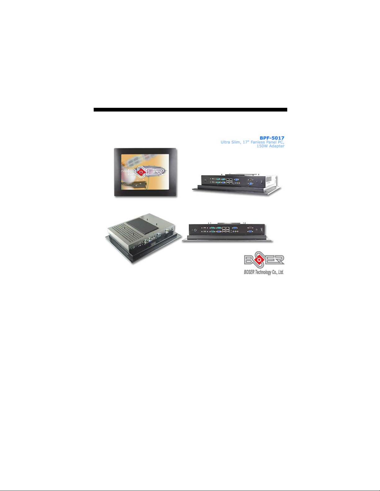
BPF-5017
Ultra Slim, 17” Fanless Panel PC,
150W Adapter
Page 2

Copyright Disclaimers
The accuracy of contents in this manual has passed through checking and review before
publishing. BOSER Technology Co., Ltd., the manufacturer and publisher, is not liable for
any infringements of patents or other rights resulting from its use. The
not be responsible for any direct, indirect, special, incidental or consequential
damages arising from the use of this product or documentation, even if advised of
the possibility of such damage(s).
This manual is copyrighted and BOSER Technology Co., Ltd. reserves all
documentation rights. Unauthorized reproduction, transmission, translation, and
storage of any form and means (i.e.,
of this document, in whole or partly, is prohibited, unless granted permission by BOSER
Technology Co., Ltd.
BOSER Technology Co., Ltd. reserves the right to change or improve the contents of
this document without due notice. BOSER Technology Co., Ltd. assumes no
responsibility for any errors or omissions that may appear in this manual, nor does
it make any commitment to update the information contained herein.
T
r
a
d
e
m
T
r
T
r
BOSER is a registered trademark of BOSER Technology Co., Ltd.
ISB is a registered trademark of BOSER Technology Co., Ltd.
Intel is a registered trademark of Intel Corporation.
Award is a registered trademark of Award Software, Inc.
AMI is a registered trademark of AMI Software, Inc.
All other trademarks, products and or product names mentioned herein are
mentioned for identification purposes only, and may be trademarks and/or
registered trademarks of their respective companies or owners.
a
a
d
e
m
a
a
d
e
m
a
r
k
s
r
k
s
r
k
s
electronic, mechanical, photocopying, recording)
manufacturer will
© Copyright 2008 BOSER Technology Co., Ltd.
All Rights Reserved.
Edition 1.0, Oct 31, 2008
Page 3

Table of Contents
Chapter 1 General Description ..................................1
1.1 Major Features....................................................................... 2
1.2 Specifications ........................................................................ 2
1.3 Dimensions ............................................................................ 4
Chapter 2 Unpacking .................................................. 5
2.1 Opening the Delivery Package............................................. 5
2.2 Inspection............................................................................... 5
Chapter 3 Hardware Installation ..............................7
3.1 WLAN Device Installation..................................................... 7
3.2 Installation AD ....................................................................... 8
3.3 Heat Sink Installation for CPU ............................................. 8
3.4 Installation SBC..................................................................... 9
3.5 HDD Cage Assembly........................................................... 10
3.6 Heat Sink Installation for Chassis ..................................... 12
3.7 Back Cover Installation....................................................... 12
3.8 Wall Mount Kit...................................................................... 13
3.9 VESA Mount Metal Stand Kit.............................................. 14
Chapter 4 Touch Screen Driver Installation ..........15
4.1 Resistive Type Touch Screen Driver Installation............. 15
4.2 SAW Type Touch Screen Driver Installation .................... 22
Page 4

Safety Instructions
The safety recommendations outlined in this section are to be read,
understood and followed before operating the product. Keep this
information in a safe place for future reference. Failure to comply with any
of the following safety procedures could result in serious damage.
Do not operate product for any purposes other than its intended use
This product is intended for indoor use only
Do not operate product if power cord is damaged in anyway
Do not insert objects into openings
Do not immerse product in water or permit liquids to spill inside
Turn off power when unattended or not in use. Unplug product before
moving it or when it is not in use for an extended period of time. The
socket-outlet shall be installed near the equipment and shall be easily
accessible
Do not alter or extend electric plug. Plug is configured for appropriate
electrical supply
Do not overload electrical outlets beyond their capacity as this can result in a
fire
NOTE: DO NOT TOUCH THE PRODUCT OR ANY OTHER SENSITIVE
COMPONENTS WITHOUT ALL NECESSARY ANTI-STATIC
PROTECTIONS.
Page 5

Life Expectancy of Constituent Parts
This section describes the life expectancy of constituent parts (backlight,
power supply, internal cooling fan and touch screen) which make up to
BPF-5017.
TFT Display Backlight
Display brightness decreases over time with use. The expected operating
lifetime of the backlight time to reach 50% initial brightness) is 30,000 hours
(assuming continuous lit state at 25 degrees C). Actual lifetime result may be
different.
Touch Screen
The operating lifetime of the touch screen is approximately 1 million
operations (as tested by mechanical manipulation under 100g of force at a
rate of two presses per second)
Page 6

This page intentionally left blank.
Page 7
Chapter 1
General Description
The BPF-5017 is a latest Industrial Panel PC, Panel PC features
anti-vibration design and is a best cost-effective alternation for users.
This precise streamline platform can be applied to Kiosk, DSA,
transaction terminal, POS, home security system, ATM system and
voting machine parking field and more.
It has a built-in ultra low power consumption Intel® mobile processor is
responsed to demands of cost-effective panel system. All of BPF series
Panel PC Support resistive touch screens, highly expandable, it is an
ideal for space-limited environments, and furthermore it supports an
optional rotational WLAN antenna for wireless network connection.
1
Page 8

Anti-vibration
With an unique anti-vibration design, All of BPF series Panel PC has
been approved for vibration tests at Intel® Pentium® M/Celeron® M
processor in the u-FCPGA 478 package in operation mode with Hard
Disk
Ultra slim design: 55~61 mm thickness
With streamlined mechanical layout, the BPF series panel PC has an
ultra slim thickness for space-limited environment. It is not only
decreases maintenance time but also saves the space considerably.
Cost-effective Fanless Embedded System
The BPF series Panel PC, the most slim, compact size, fanless
embedded computer, is powered by an ultra low power processor,
Intel® Pentium® M/Celeron® M processor in the u-FCPGA 478
package onboard, The total power consumption of the system is under
27W merely. It generates the best valve for both power usage and cost
saving. Without hard disk space and extra add-on cards, All of BPF
series panel PC presents an ultra slim design and provides a
cost-effective alternative for users. I/O feature contains VGA, COM,
dual LAN, USB 2.0, and PS/2 connectors. Moreover.
1.1 Major Features
The BPF-5017 series comes with the following features:
Ultra slim, fanless, aluminum front panel design
17” TFT color panel display
Built-in touch screen, HS-1752, 150W adapter
Provides Intel® P-M/C-M, WLAN Module (optional)
Onboard graphics, dual GB ethernet, audio controller
2.5” SATA HDD space x 2, slim CD-ROM space x 1
BPF-5017-C provides COM x 6, USb2.0 x 6
1.2 Specifications
System
SBC Model
HS-1752
CPU
Intel® Pentium® M/Celeron® M processor in the u-FCPGA 478 package
(optional)
BIOS
Award BIOS with 4Mb SPI Flash EEPROM
System Chipset:
Intel® 915GME/ICH6-M
2
Page 9

System Memory
Two 240-pin DIMM socket up to 2GB DDR2 SDRAM
Display Chipset
Intel® 915GME
Audio Chipset
Realtek ALC655 5.1CH audio codec
Ethernet Chipset
Dual RealTek RTL8111B 10/100/1000 Mbps LAN
Provides Wireless LAN Module (optional)
Drive Bay
2 x 2.5” SATA HDD space
1 x Slim CD-ROM space
Watchdog Timer
Reset: 1 sec.~255 min. and 1 sec. or 1 min./step
Panel & Touch Screen
LCD Size
17”
Max Resolution
1280 x 1024 pixels
Brightness (cd/m
300 (center, Typ)@7.5mA
Contrast Ratio
800:1
LCD Color
16.7M color (RGB 6-bits + FRC data)
Pixel Pitch (mm)
0.264(H) x 0.264(V)
OSD
Provides OSD function
Touch Screen
17” resistive
2
)
Mechanical & Environmental
Front Panel Color
Black
Dimensions (LxHxW)
45.0 x 37.0 x 8.95 cm
Operation Temperature
0~+45 degrees C
Storage Temperature
-20~+70 degrees C
EMC
FCC/CE
3
Page 10
Front Panel Protection
IP65 Compliance
Power Adapter
150W adapter
I/O Interface
External I/O
USB2.0 x 6, COM x 6, VGA, LAN x 2, PS/2 KB/MS, Line In, Line Out, MIC
In
Rear I/O
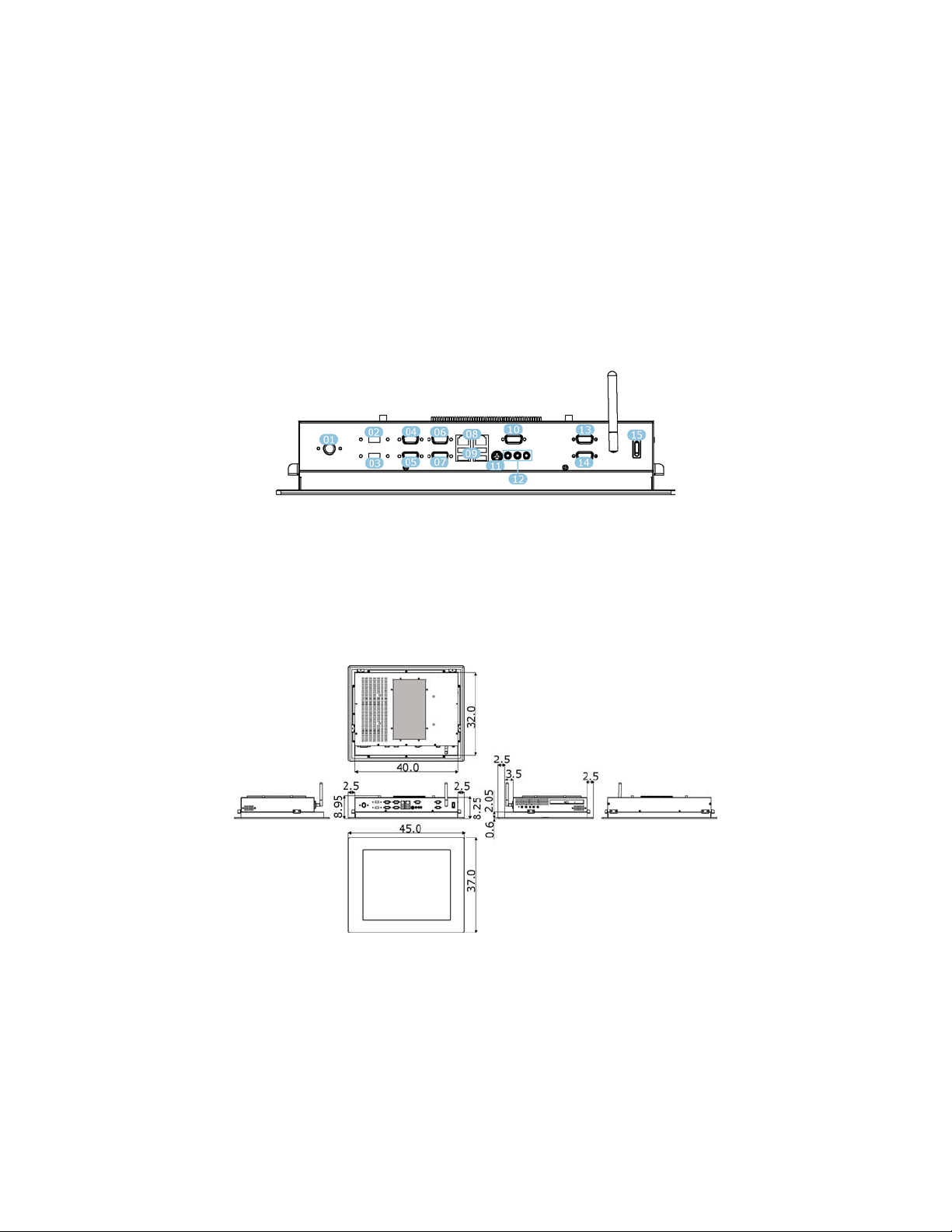
01. Power In 06. COM 5 11. KB/MS
02. USB2.0 07. VGA 12. Audio
03. USB2.0 08. LAN * 2 13. COM 4
04. COM 1 09. USB2.0 *4 14. COM 6
05. COM 2 10. COM 3 15. ON/OFF
1.3 Dimensions
Dimension measure in mm
4
Page 11

Chapter 2
Unpacking
2.1 Opening the Delivery Package
The BPF-5017 is packed with an anti-static bag. The board contains
sensitive electricity components that are easily damaged by static
(electricity). Do not remove the anti-static wrapping until proper
grounding have been taken. Safety instructions has been described
the anti-static precautions and procedures in the previous.
2.2 Inspection
After unpacking the Panel PC, place it on a raised surface and carefully
inspect it for any damage that might have occurred during shipment.
Ground the board and exercise extreme careful to prevent and damage
to the board from static.
The BPF-5017 delivery package contains the following items:
BPF-5017 x 1
Power Cable x 1
System Board Driver CD x 1
System Board User’s Manual x 1
BPF-5017 User’s Manual x 1
Touch Screen Driver CD x 1
It is recommended that user keeps all the parts of the delivery package
intactness and store them in a safe/dry place for any reasons that
require for returning the product. In case you find any missing and/or
damaged items from the list, please contact your dealer or sale
representatives immediately.
5
Page 12

This page intentionally left blank.
6
Page 13
Chapter 3
Hardware Installation
This chapter illustrates how to install components into the Panel PC
system. External interface please refers to system board’s manual.
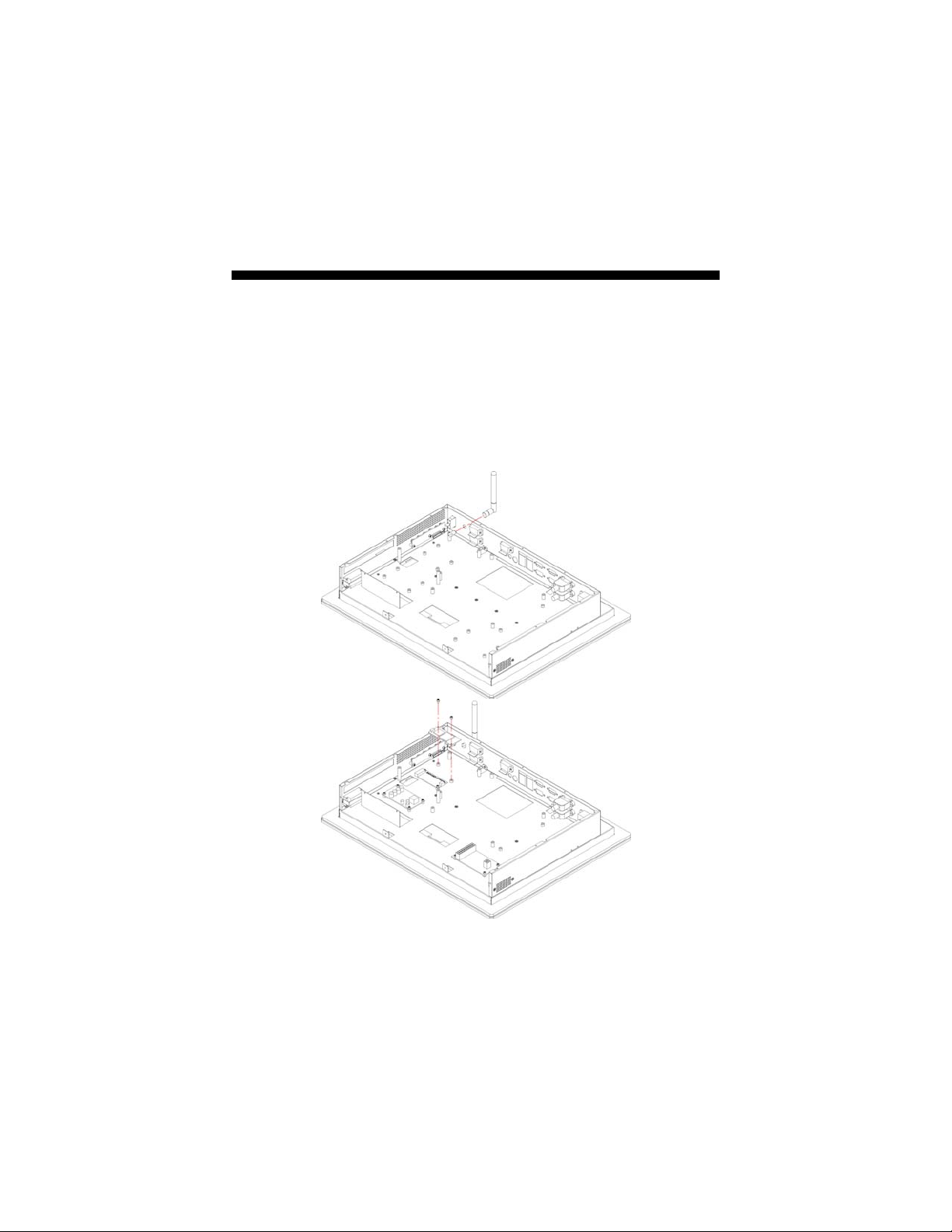
3.1 WLAN Device Installation
1. User can install the Network Card and Network antenna
module us below.
7
Page 14
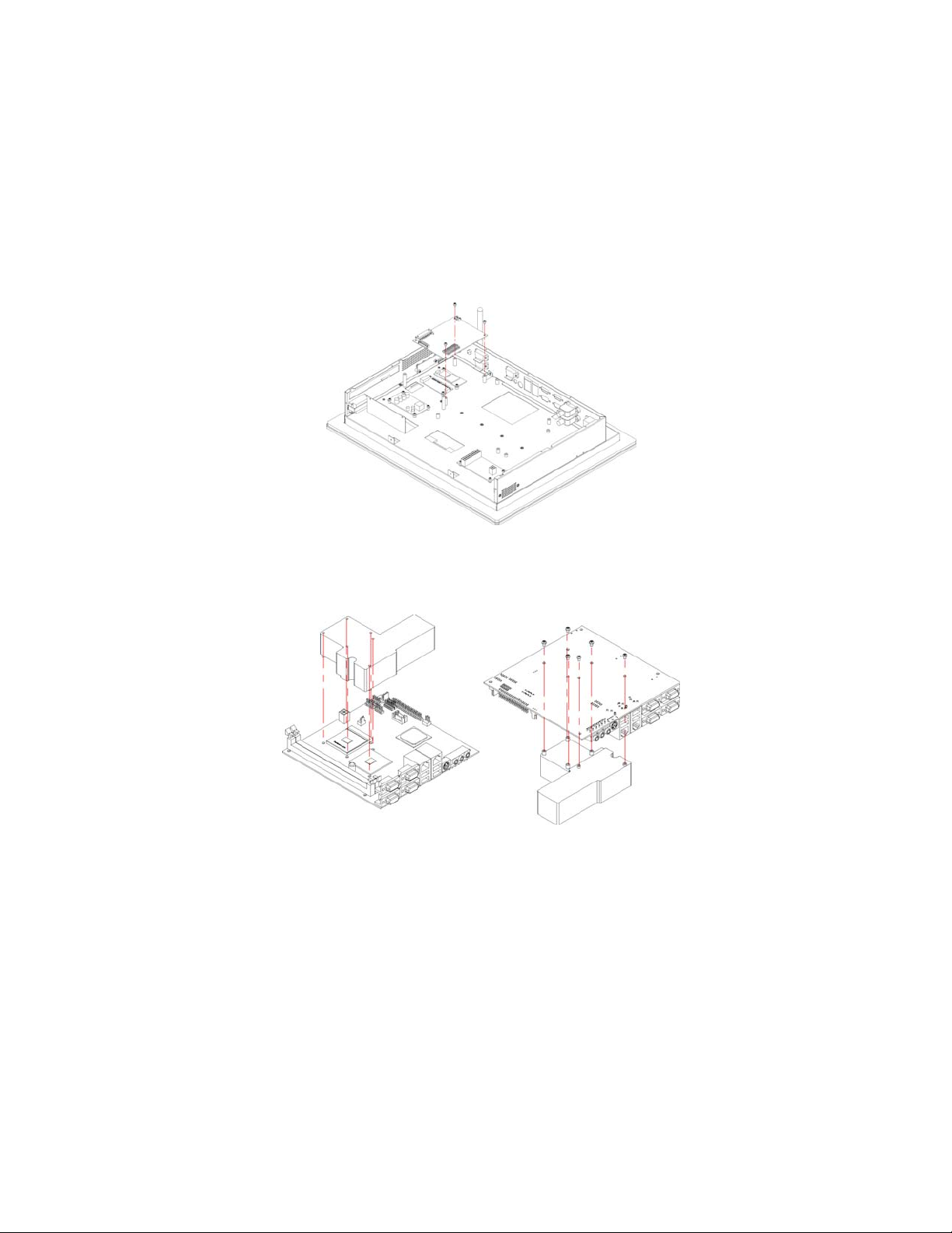
3.2 Installation AD
1. Follow the photo instruction install the AD into the chassis.
3.3 Heat Sink Installation for CPU
1. Follow the photo instruction install the heat sink into the SBC
with 6 screws evenly.
8
Page 15
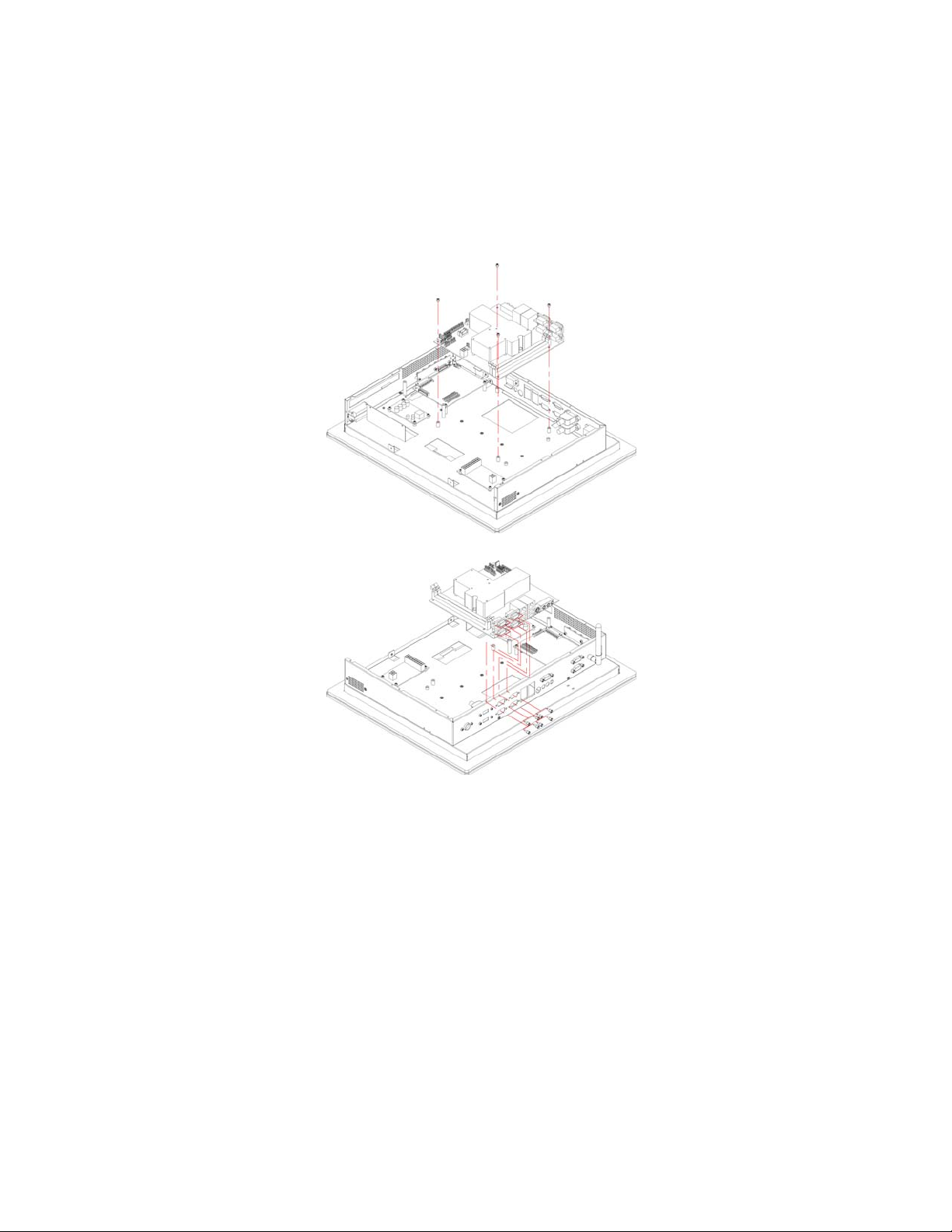
3.4 Installation SBC
1. Install the SBC with chassis.
2. Use Eight screws install SBC with front panel.
9
Page 16
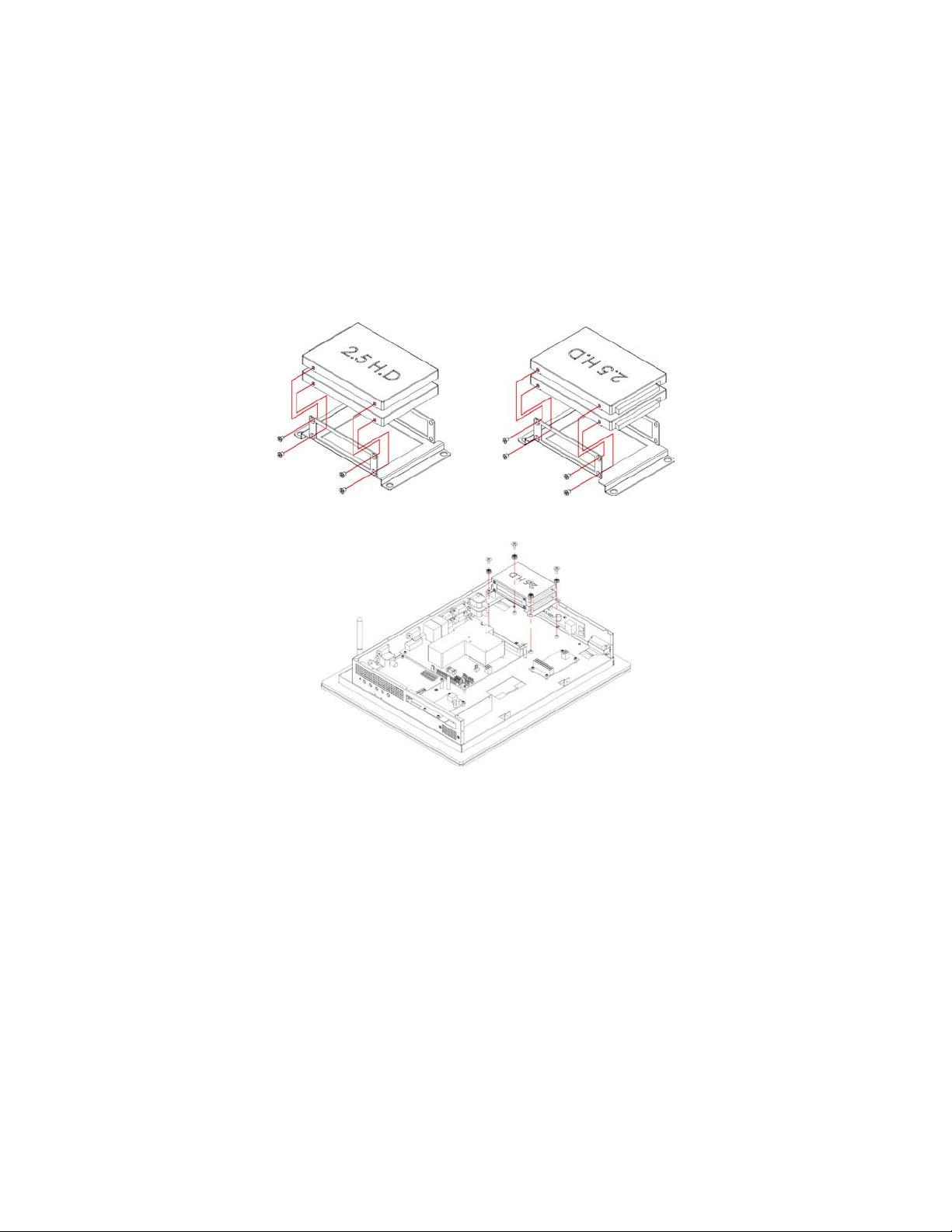
3.5 HDD Cage Assembly
1. Follow the photo instruction install the HDD into the HDD
mounting bracket.
2. Follow the photo instruction install the HDD KIT into the
chassis.
10
Page 17
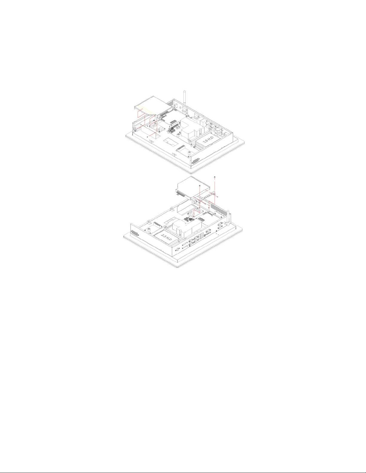
3. Follow the photo instruction install the CD-ROM into the
CD-ROM mounting bracket.
11
Page 18
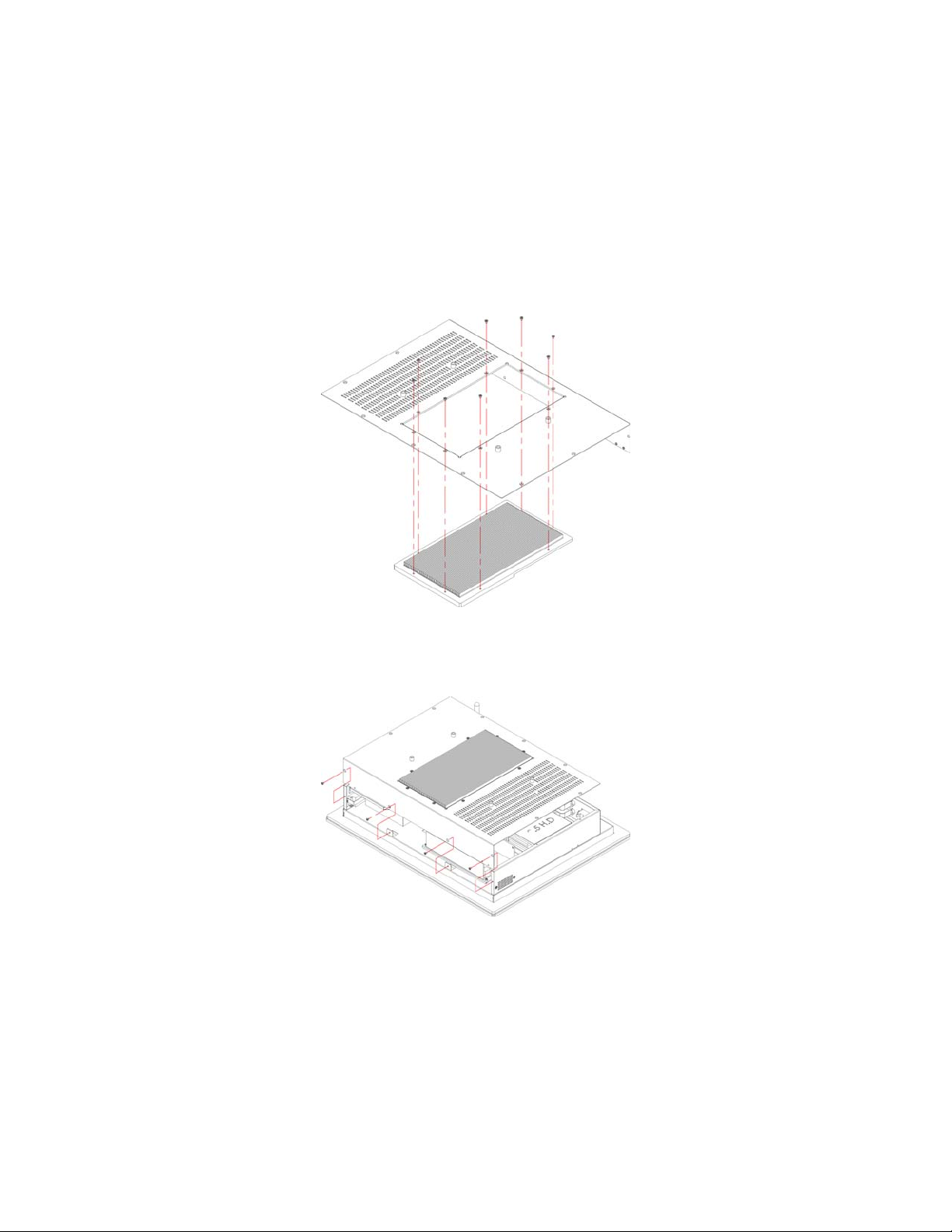
3.6 Heat Sink Installation for Chassis
1. Follow the photo instruction install the large heat sink into the
back cover of the chassis.
3.7 Back Cover Installation
1. Follow the photo instruction install the back cover into the
chassis.
12
Page 19
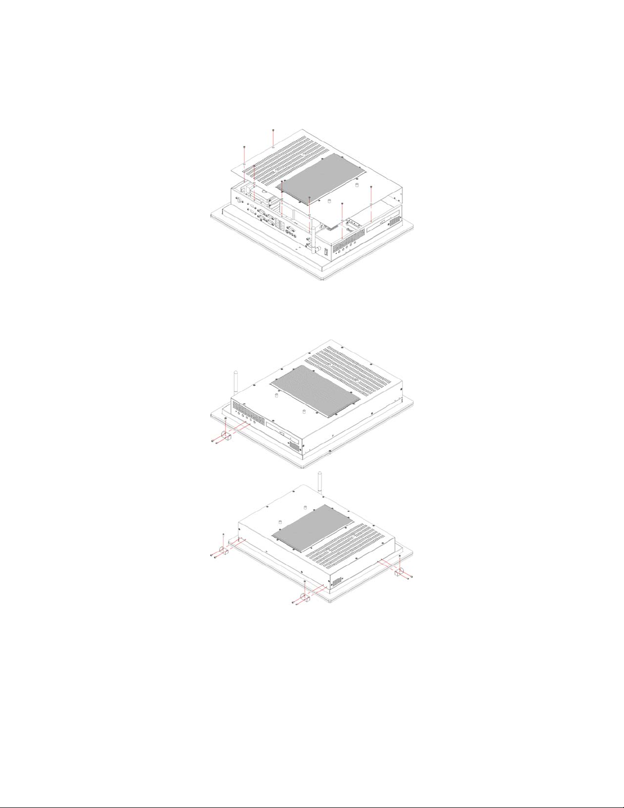
3.8 Wall Mount Kit
1. Follow the photo instruction install the wall mount kit into the
chassis.
13
Page 20
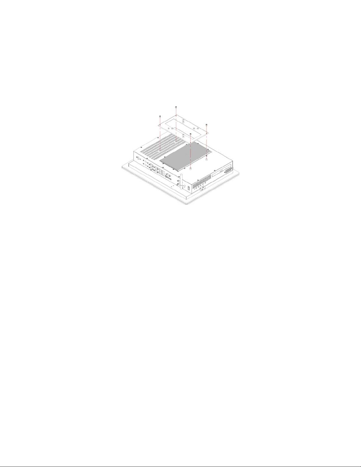
3.9 VESA Mount Metal Stand Kit
14
Page 21
Chapter 4
Touch Screen Driver Installation
This chapter illustrates the detail information of touch screen driver
installation procedures. The utility disk that came with the delivery
package contains an auto-run program that invokes the installation
programs for the touch screen driver. The following sections describe
the installation procedures of driver based on WIN2000 operating
systems. Other operation system may slightly different.
4.1 Resistive Type Touch Screen Driver
Installation
4.1.1 Installing Touch Screen Driver in WIN95/98
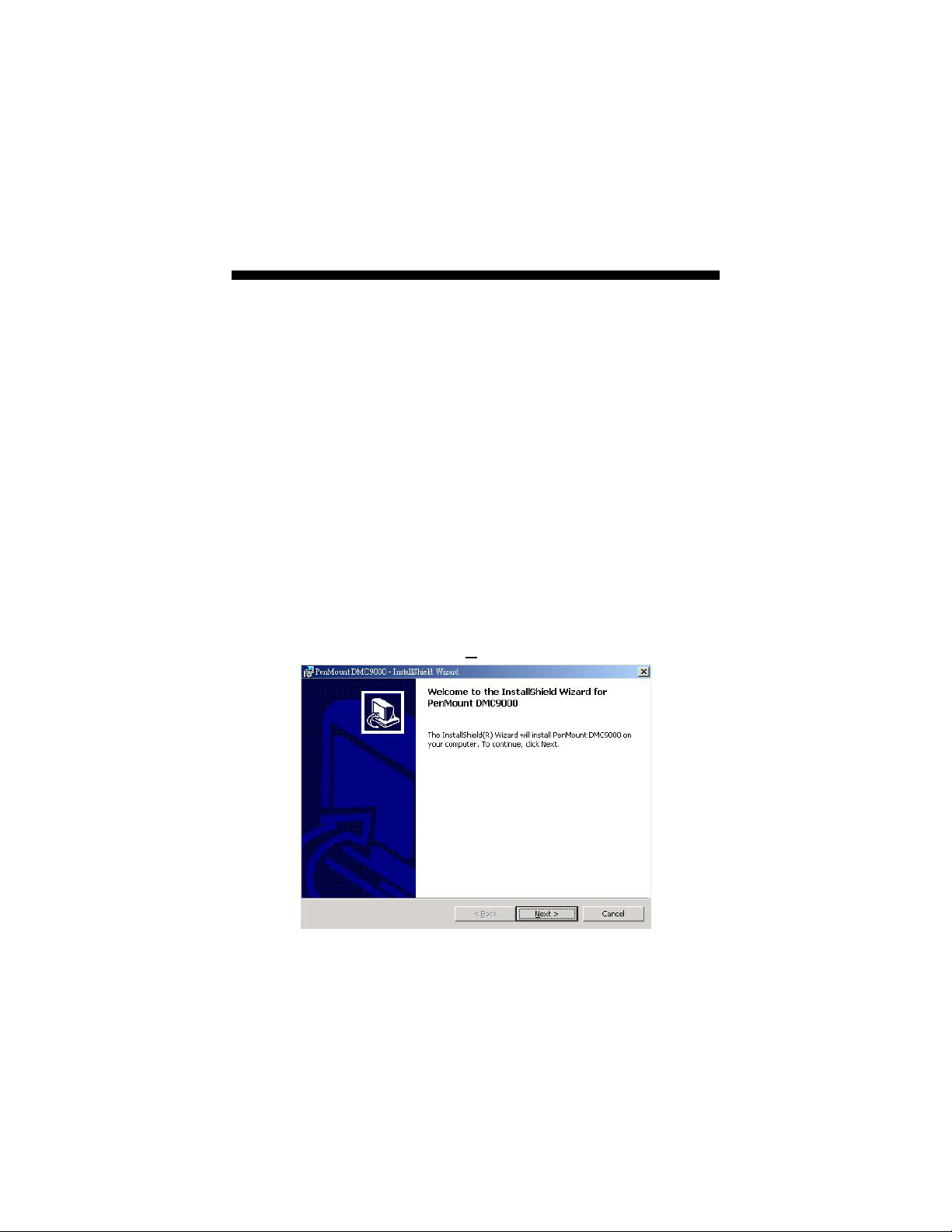
1. Insert Utility CD disk to your CD-ROM drive. The main menu
will pop up as shown below.
2. The screen displays copying “Installation Wizard” and
“PenMount Utilities Installation” screen plus “welcome”
message appear, click on N
ext>.
15
Page 22
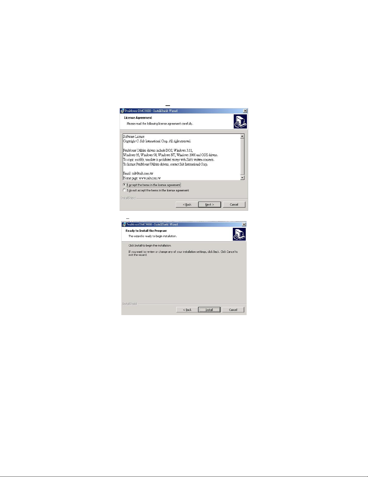
3. The next screen is “Software License Agreement”, select “I
accept” and click on N
4. Click “Install” to begin the installation.
ext>.
16
Page 23
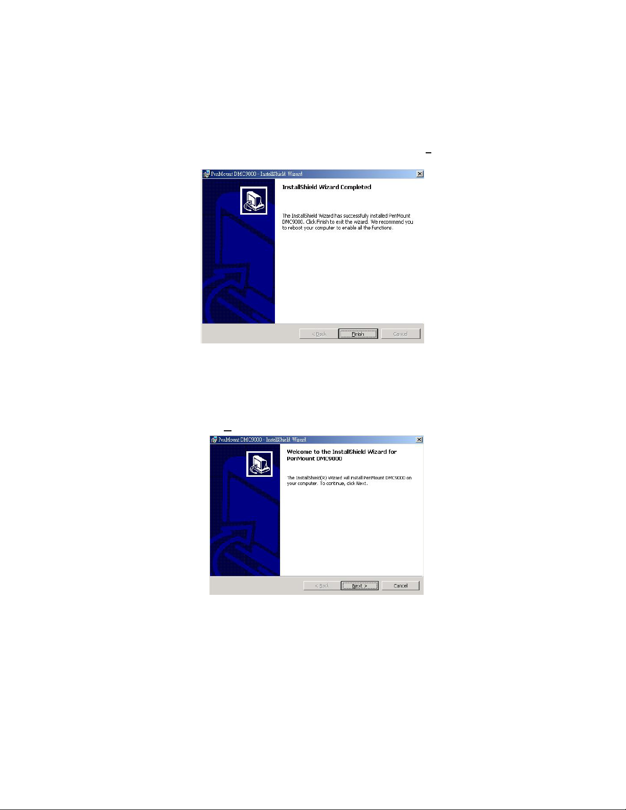
5. Once the Install Shield Wizard finishes updating your system,
it will prompt you to restart the computer. Click on F
exit the wizard.
inish to
4.1.2 Installing Touch Screen Driver in WIN2000
1. Insert Utility CD Disk to your CD-ROM drive. The main menu
will pop up as shown below.
2. The screen displays copying Installation Wizard and PenMount
Utilities Installation screen plus welcome message appear,
click on N
ext>.
17
Page 24
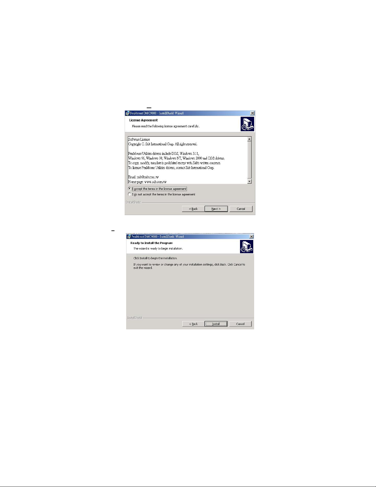
3. The next screen is Software License Agreement, select I accept
and click on N
4. The next screen is Ready to Install the Program, click on
I
nstall.
ext>.
18
Page 25
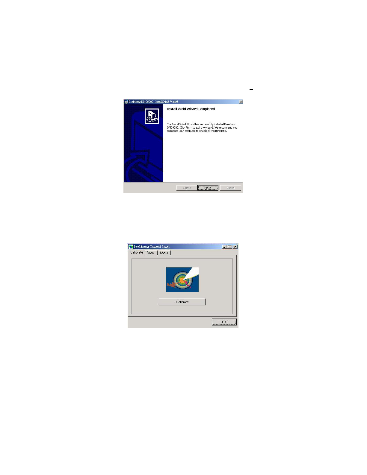
5. Once the Install Shield Wizard finishes updating your system,
it will prompt you to restart the computer. Click on F
exit the wizard.
inish to
4.1.3 PenMount Control Panel
Calibrate
To adjust the display with touch screen, click on “Calibrate” button and
follow the calibrate point to do the calibration, there are five points on
screen for calibration.
19
Page 26
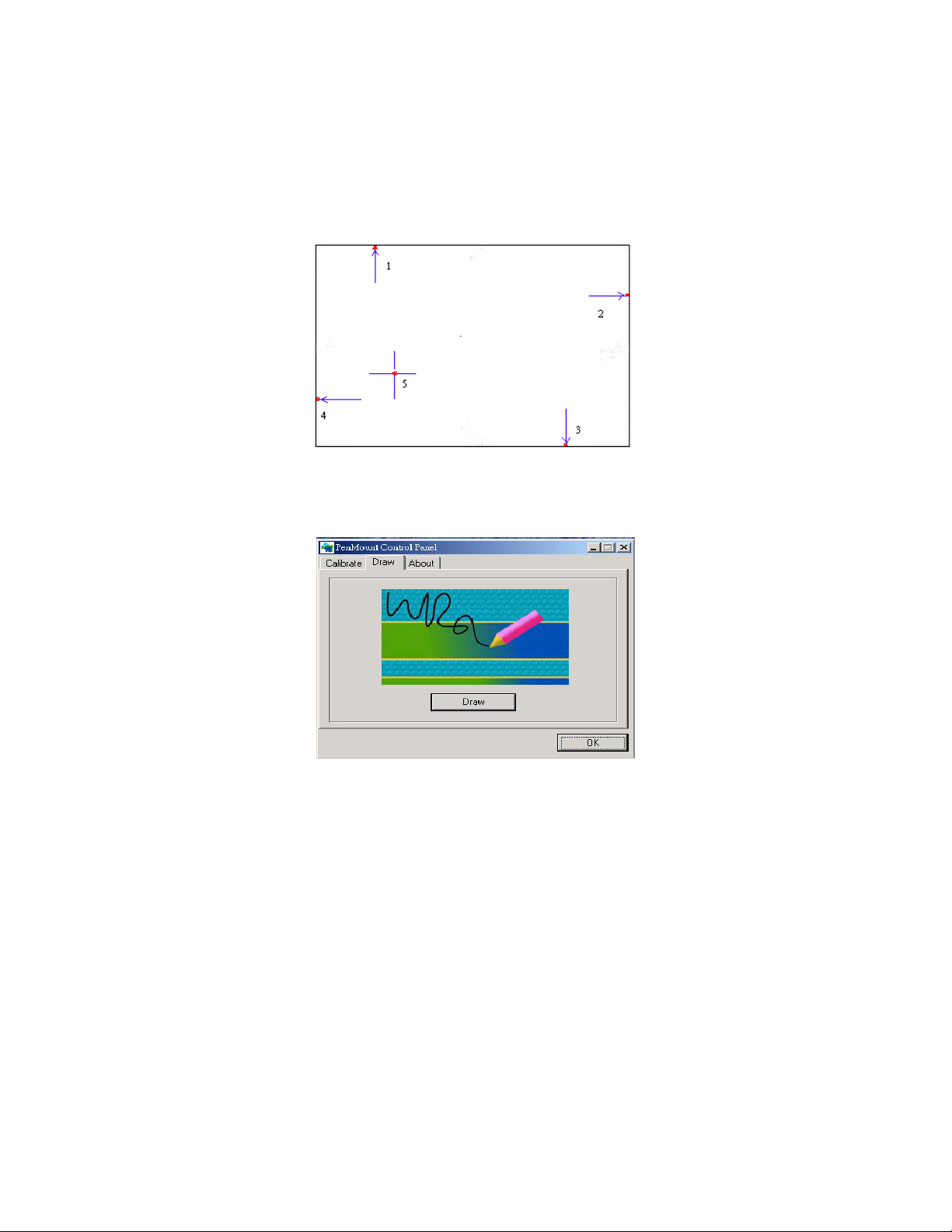
Draw
Test or demonstrate PenMount touch screen operation, also the touch
location is shown on the display, touch DRAW to start.
About
It shows information about PenMount controller and driver version.
20
Page 27
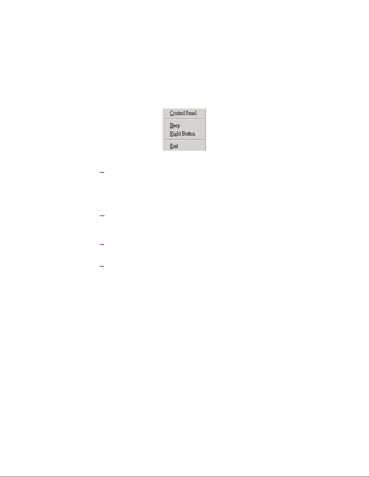
4.1.4 PenMount Monitor
The PenMount monitor icon is shown in the menu bar of Windows
system when turn on PenMount monitor from PenMount Utilities.
There are several functions on PenMount monitor:
Control Panel
When select this function, there is a mouse icon shown in the
right-button place of screen. It shows Left Button being as default for
normal use, change Right/Left button by clicking the mouse icon box.
Blue area expresses what button has been selected or actived.
Right Button
Change Right/Left button by clicking the mouse icon box. Blue area
expresses what button has been or actived.
Beep
Turn on or off beep sound.
Exit
Close the PenMount Monitor function.
21
Page 28
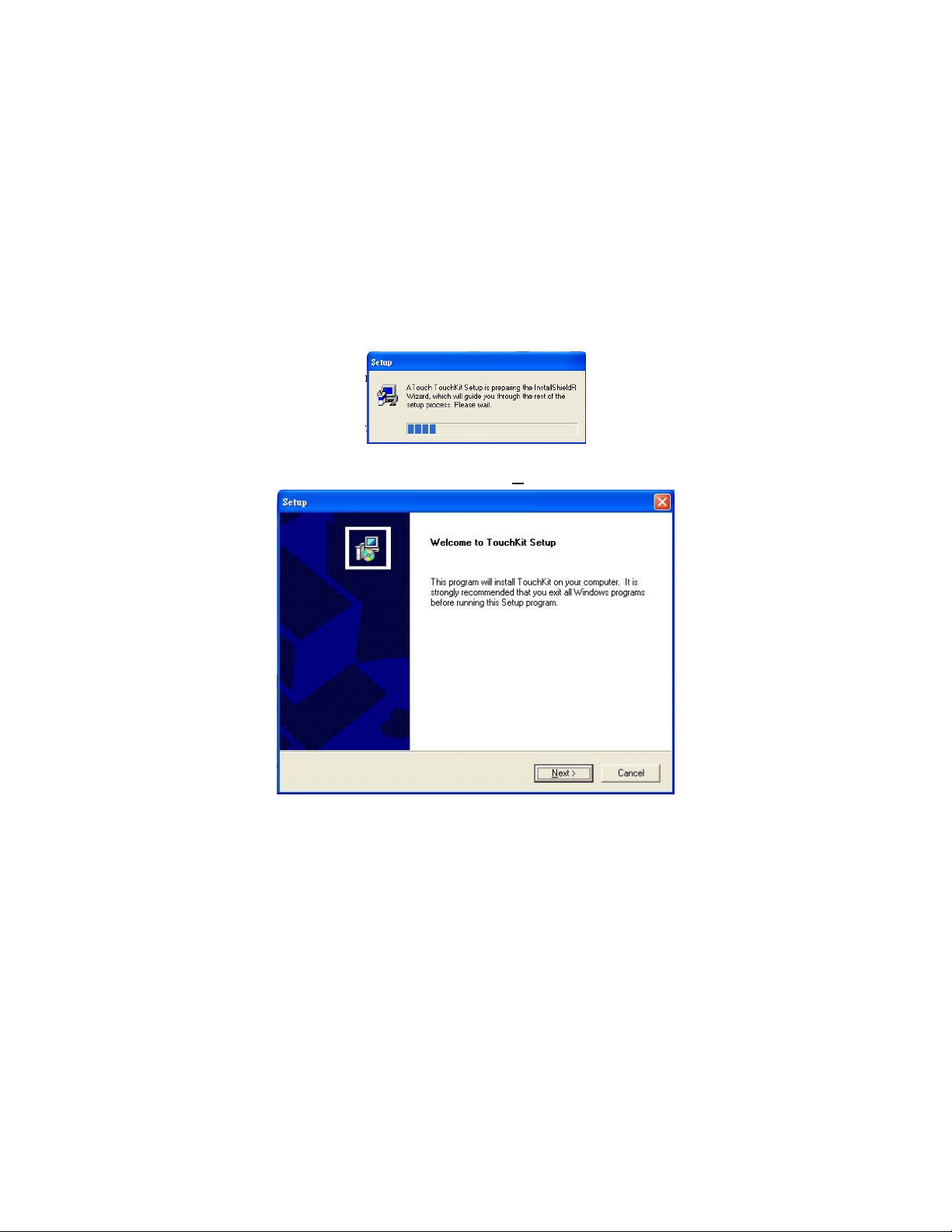
4.2 SAW Type Touch Screen Driver
Installation
1. Insert Utility CD disk to your CD-ROM drive. The main menu
will pop up as shown below.
2. The screen displays copying “Setup” and “TouchKit Setup”
screen message appear, click on N
ext>.
22
Page 29
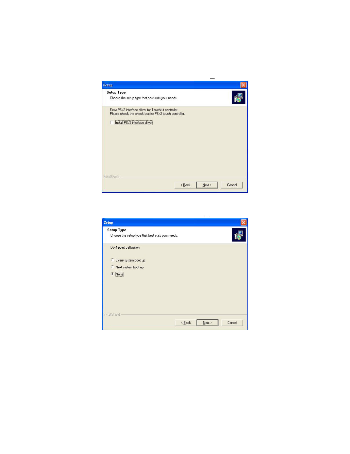
3. The next screen is as below, and click on Next>.
NOTE:
The default is unchecked.
4. The next screen is choosing the setup type that “Do 4 point
calibration”, select “None” and click on N
ext>.
NOTE:
Check the necessary button for your need.
23
Page 30
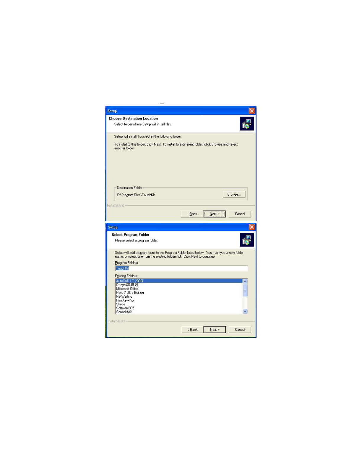
5. Choose the drivers install location, you desire or leave if as
default and click on N
ext>.
24
Page 31
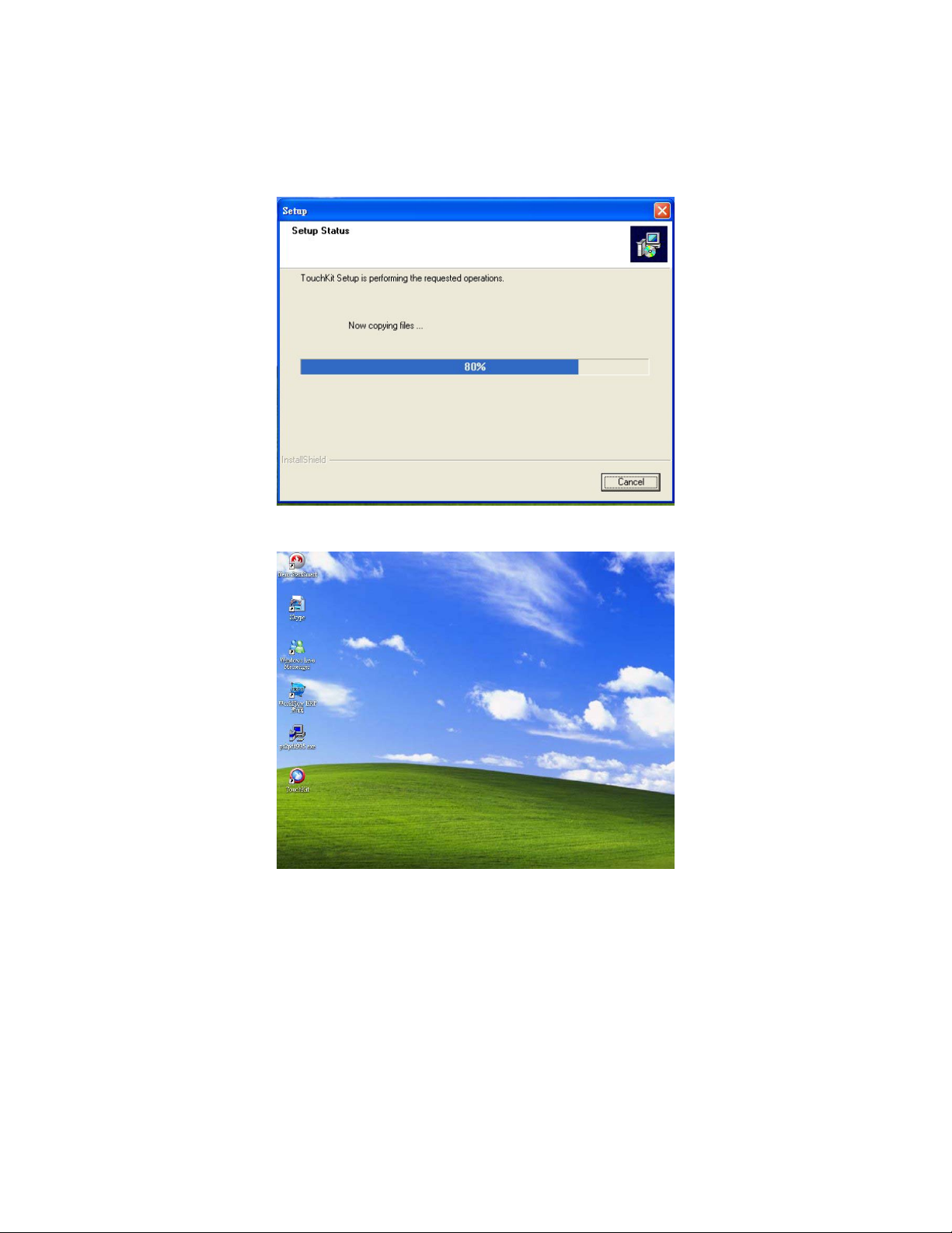
6. When the TouchKit setup finish, you will see an icon names
“TouchKit” in your desktop.
25
Page 32

This page intentionally left blank.
26
 Loading...