

Page 1

BPC-3600
6.4” Industrial Panel PC
with MainBoard, CF, TV-Out,
Touch Screen, Power Adapter
Page 2

Copyright Disclaimers
The accuracy of contents in this manual has passed thorough checking and review before
publishing. BOSER Technology Co., Ltd., the manufacturer and publisher, is not liable for
any infringements of patents or other rights resulting from its use. The
not be responsible for any direct, indirect, special, incidental or consequential
damages arising from the use of this product or documentation, even if advised of
the possibility of such damage(s).
This manual is copyrighted and BOSER Technology Co., Ltd. reserves all
documentation rights. Unauthorized reproduction, transmission, translation, and
storage of any form and means (i.e.,
of this document, in whole or partly, is prohibited, unless granted permission by BOSER
Technology Co., Ltd.
BOSER Technology Co., Ltd. reserves the right to change or improve the contents of
this document without due notice. BOSER Technology Co., Ltd. assumes no
responsibility for any errors or omissions that may appear in this manual, nor does
it make any commitment to update the information contained herein.
T
r
a
d
e
m
T
r
T
r
BOSER is a registered trademark of BOSER Technology Co., Ltd.
ISB is a registered trademark of BOSER Technology Co., Ltd.
Intel is a registered trademark of Intel Corporation.
Award is a registered trademark of Award Software, Inc.
AMI is a registered trademark of AMI Software, Inc.
All other trademarks, products and or product names mentioned herein are
mentioned for identification purposes only, and may be trademarks and/or
registered trademarks of their respective companies or owners.
a
a
d
e
m
a
a
d
e
m
a
r
k
s
r
k
s
r
k
s
electronic, mechanical, photocopying, recording)
manufacturer will
© Copyright 2007 BOSER Technology Co., Ltd.
All Rights Reserved.
Edition 1.1, May 15, 2009
Page 3

Table of Contents
Chapter 1 General Description ..................................1
1.1 Major Features....................................................................... 2
1.2 Specifications ........................................................................ 2
1.3 Panel Specifications ............................................................. 3
1.4 Dimensions ............................................................................ 3
Chapter 2 Unpacking .................................................. 5
2.1 Opening the Delivery Package............................................. 5
2.2 Inspection............................................................................... 5
Chapter 3 Hardware Installation ..............................7
3.1 Remove Hard Disk Drive....................................................... 7
3.2 Install Hard Disk Drive .......................................................... 8
Chapter 4 Touch Screen Driver Installation ............9
4.1 Touch Screen Driver Installation ......................................... 9
4.1.1 Installing Touch Screen Driver in WIN95/98...................................9
4.1.2 Installing Touch Screen Driver in WIN2000 ................................... 11
4.2 Driver Functions.................................................................. 14
4.2.1 PenMount Control Panel............................................................................14
4.2.2 PenMount Monitor ........................................................................................15
Page 4

Declaration of Conformity -- CE Mark
BOSER Technology hereby acknowledges that compliance testing in
accordance with applicable standards of the EU’s EMC Directive,
89/336/EEC, was successfully completed on a sample of the equipment
identified below:
Equipment Class: Information Technology Equipment
Product Model Series: BPC-3600
This Product Complies With: EN55022: Class A for Radiated emissions
EN50082-2: Heavy Industrial EMC Immunity
We, the undersigned, hereby declare that the equipment specified above
conforms to the above directives and standards.
Manufacturer:
BOSER TECHNOLOGY CO., LTD.
Page 5

Safety Instructions
The safety recommendations outlined in this section are to be read,
understood and followed before operating the product. Keep this
information in a safe place for future reference. Failure to comply with any
of the following safety procedures could result in serious hazard.
Do not operate product for any purposes other than its intended use
This product is intended for indoor use only
Do not operate product if power cord is damaged in anyway
Do not insert objects into openings
Do not immerse product in water or permit liquids to spill inside
Turn off power when unattended or not in use. Unplug product before
moving it or when it is not in use for an extended period of time. The
socket-outlet shall be installed near the equipment and shall be easily
accessible
Do not alter or extend electric plug. Plug is configured for appropriate
electrical supply
Do not overload electrical outlets beyond their capacity as this can result in a
fire
NOTE: DO NOT TOUCH THE PRODUCT OR ANY OTHER SENSITIVE
COMPONENTS WITHOUT ALL NECESSARY ANTI-STATIC
PROTECTIONS.
Page 6

Life Expectancy of Constituent Parts
This section describes the life expectancy of constituent parts (backlight,
power supply, internal cooling fan and touch screen) which make up to
BPC-3600 series.
TFT Display Backlight
Display brightness decreases over time with use. The expected operating
lifetime of the backlight time to reach 50% initial brightness) is 30,000 hours
(assuming continuous lit state at 25 degrees C). Actual lifetime before
replacement is about 30,000 hours, although this depends on operating
conditions.
Touch Screen
The operating lifetime of the touch screen is approximately 1 million
operations (as tested by mechanical manipulation under 100g of force at a
rate of two presses per second)
Page 7
Chapter 1
General Description
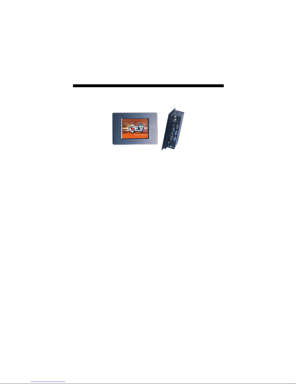
The BPC-3600 series is an industrial Panel PC. The rear design of
BPC-3600 series enhanced the disassembly process when required. It
also supports various mounting solution like wall-mount, panel-mount,
or desktop for different application.
The BPC-3600 series has a 6.4” display and an optional touch screen
that operate under all types of working environment.
This model can accommodate BOSER’s HS-2605 embedded engine
board. The BPC-3600 series provides CF, CRT, TV-Out, TJ-45, Line
In, Audio Out, KB/MS, COM and USB ports.
The BPC-3600 series is IBM PC/AT compatible and can
draw from a large body of hardware and software
resources worldwide.
The user can select the operating system he wants to
use just like an ordinary personal computer. An
operating system such an MS-DOS, Windows can be
selected to suit the application.
The BPC-3600 series features an all-in-one flat display.
Keyboard less operations are possible through the use
of a touch screen. In addition to a watchdog timer
indispensable in FA applications.
You can select from a broad range of variations to arrive at the
optimum configuration for your application and budget.
1
Page 8

1.1 Major Features
The BPC-3600 series comes with the following features:
BPC-3600-C
Aluminum front panel
6.4” high brightness TFT color panel display
Built-in touch screen, mainboard, VIA Eden 500/667MHz CPU,
+5V/+12V power adapter
Onboard graphics, Ethernet, audio controller
CF, TV-Out, DOC, COM, USB port
2.5” HDD space x 1
4cm ball bearing cooling fan x 1
Open frame type (optional)
1.2 Specifications
BPC-3600-C
CPU: VIA Eden 500/667MHz CPU (500MHz fanless)
Memory: One SO-DIMM socket supporting up to 512MB
Chipset: VIA VT8606/VT82C686B
Touch Screen: 6.4” resistive touch screen
Display: Onboard graphics controller; provides TV-Out function
Ethernet: Onboard 10/100 Based controller
Audio: Onboard 3D audio controller
Storage:
Type I/II CF adapter x 1
2.5” HDD space x 1
Serial Port: 3 ports
USB: USB port x 2
Keyboard/Mouse: PS/2 6-pin Mini DIN
DiskOnChip: DiskOnChip socket supporting memory sizes of
up to 288MB
BIOS: AMI PnP Flash BIOS
Watchdog Timer: Sets 1/2/10/20/110/220 seconds activity
trigger with NMI or Reset
Power In: +5V/+12V power adapter
Thermal System: 4cm ball bearing cooling fan x 1
Temperature: 0~45°C (operating); -20~+70°C (storage)
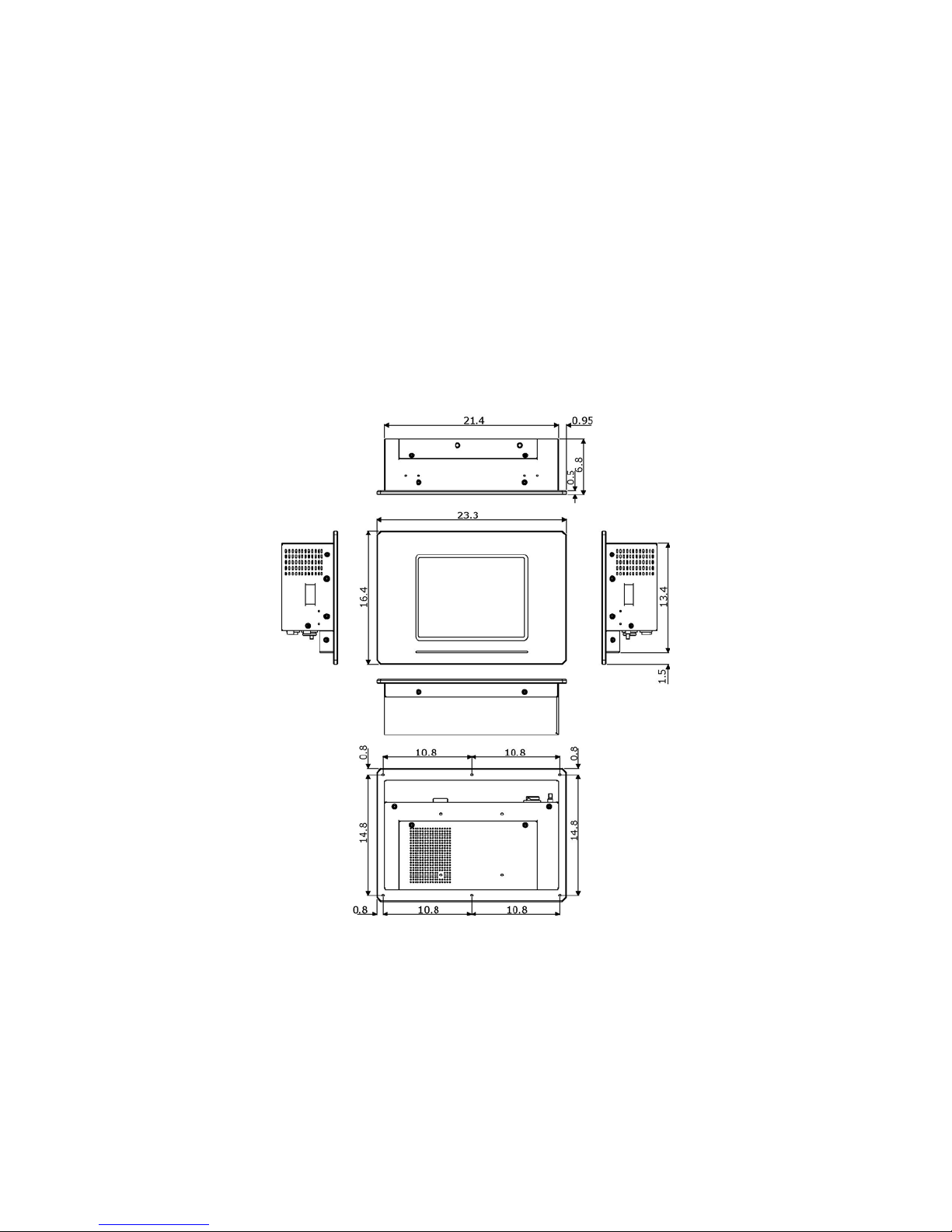
Dimensions: 23.3(L) x 16.4(H) x 6.8(W) cm
2
Page 9
1.3 Panel Specifications
Screen Size: 6.4 inches
Display Format: R x 640, G, B x 480
Pixel Pitch: 0.2025(H) x 0.2025(V) m/m
Brightness: 400 cd/m
Contrast Ratio: 400:1
MTBF: 15,000 hrs.
2
1.4 Dimensions
3
Page 10

This page intentionally left blank.
4
Page 11

Chapter 2
Unpacking
2.1 Opening the Delivery Package
The BPC-3600 series is packed in an anti-static bag. The board has
components that are easily damaged by static electricity. Do not
remove the anti-static wrapping until proper precautions have been
taken. Safety instructions in front of this manual describe anti-static
precautions and procedures.
2.2 Inspection
After unpacking the Panel PC, place it on a raised surface and carefully
inspect the board for any damage that might have occurred during
shipment. Ground the board and exercise extreme care to prevent
damage to the board from static electricity.
Integrated circuits will sometimes come out of their sockets during
shipment. Examine all integrated circuits, particularly the BIOS,
processor, memory modules, ROM-Disk, and keyboard controller chip
to ensure that they are firmly seated. The BPC-3600 series delivery
package contains the following items:
BPC-3600-C x 1
Power Cable x 1
Drive CD Disk x 1
System Board User’s Manual x 1
BPC-3600-C User’s Manual x 1
Touch Screen Drive Diskette x 1 (optional)
It is recommended that you keep all the parts of the delivery package
intact and store them in a safe/dry place for any unforeseen event
requiring the return shipment of the product. In case you discover any
missing and/or damaged items from the list of items, please contact
your dealer immediately.
5
Page 12

This page intentionally left blank.
6
Page 13
Chapter 3
Hardware Installation
This chapter tells how to install components into the Panel PC system.
External interface please refers to system board’s manual.
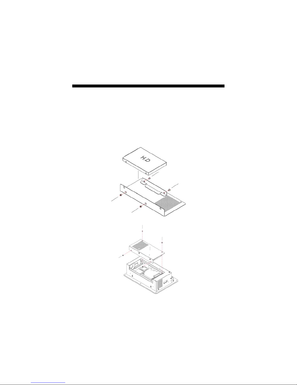
3.1 Remove Hard Disk Drive
1. Please loose screws and detach the HDD module from main
chassis.
2. Remove the HDD form rear cover.
7
Page 14
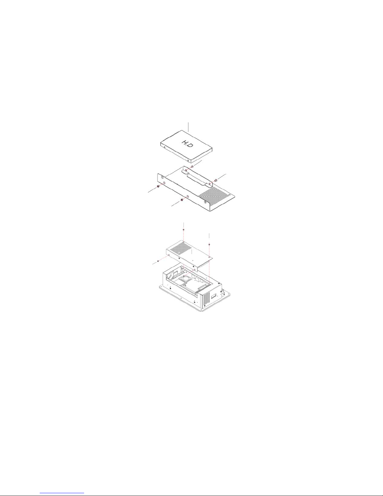
3.2 Install Hard Disk Drive
1. Please attach the HDD to rear cover and fasten screws.
2. Install the HDD module onto main chassis.
8
Page 15
Chapter 4
Touch Screen Driver Installation
This chapter contains the detailed information of touch screen driver
installation procedures. The utility disk that came with the delivery
package contains an auto-run program that invokes the installation
programs for the touch screen driver. The following sections describe
the installation procedures of driver based on WIN2000 operating
systems. It is recommended that you install the drivers matching the
sections listed in this chapter.
4.1 Touch Screen Driver Installation
4.1.1 Installing Touch Screen Driver in WIN95/98
1. Insert Utility CD disk to your CD-ROM drive. The main menu
will pop up as shown below.
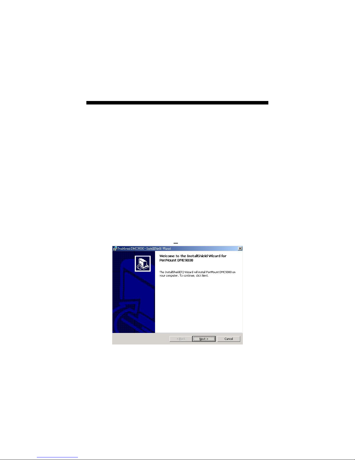
2. The screen displays copying “Installation Wizard” and
“PenMount Utilities Installation” screen plus “welcome”
message appear, click on N
ext>.
9
Page 16
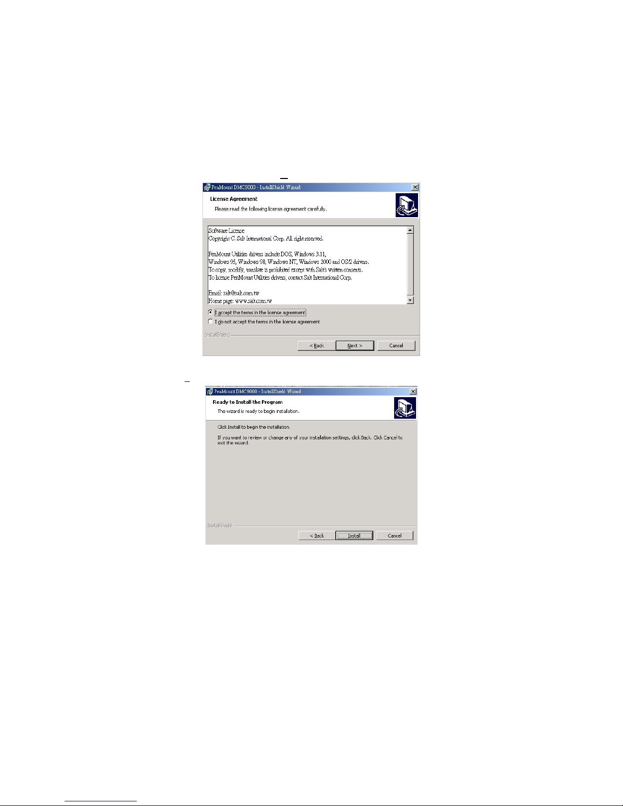
3. The next screen is “Software License Agreement”, select “I
accept” and click on N
4. The next screen is Ready to Install the Program, click on
I
nstall.
ext>.
10
Page 17
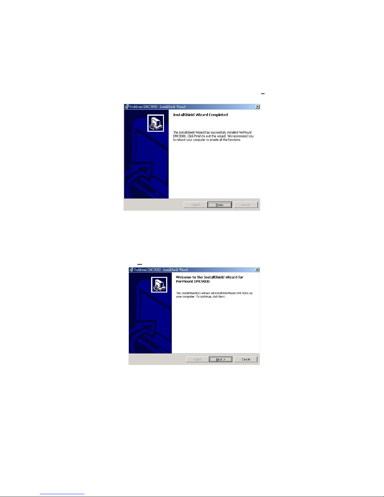
5. Once the Install Shield Wizard finishes updating your system,
it will prompt you to restart the computer. Click on F
exit the wizard.
inish to
4.1.2 Installing Touch Screen Driver in WIN2000
1. Insert Utility CD Disk to your CD-ROM drive. The main menu
will pop up as shown below.
2. The screen displays copying Installation Wizard and PenMount
Utilities Installation screen plus welcome message appear,
click on N
ext>.
11
Page 18
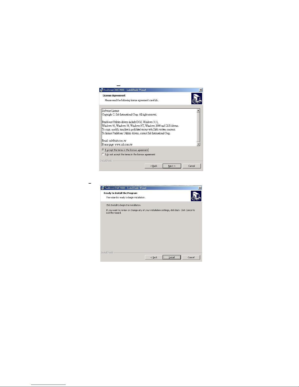
3. The next screen is Software License Agreement, select I accept
and click on N
4. The next screen is Ready to Install the Program, click on
I
nstall.
ext>.
12
Page 19
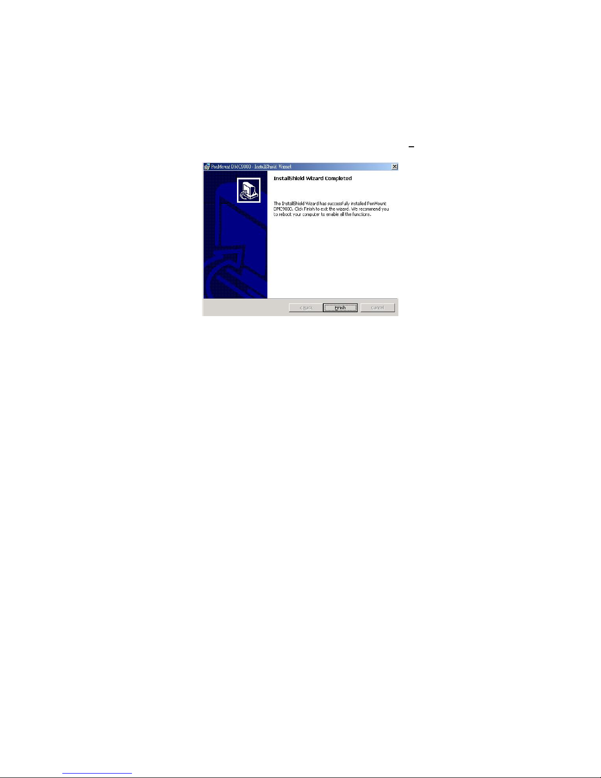
5. Once the Install Shield Wizard finishes updating your system,
it will prompt you to restart the computer. Click on F
exit the wizard.
inish to
13
Page 20
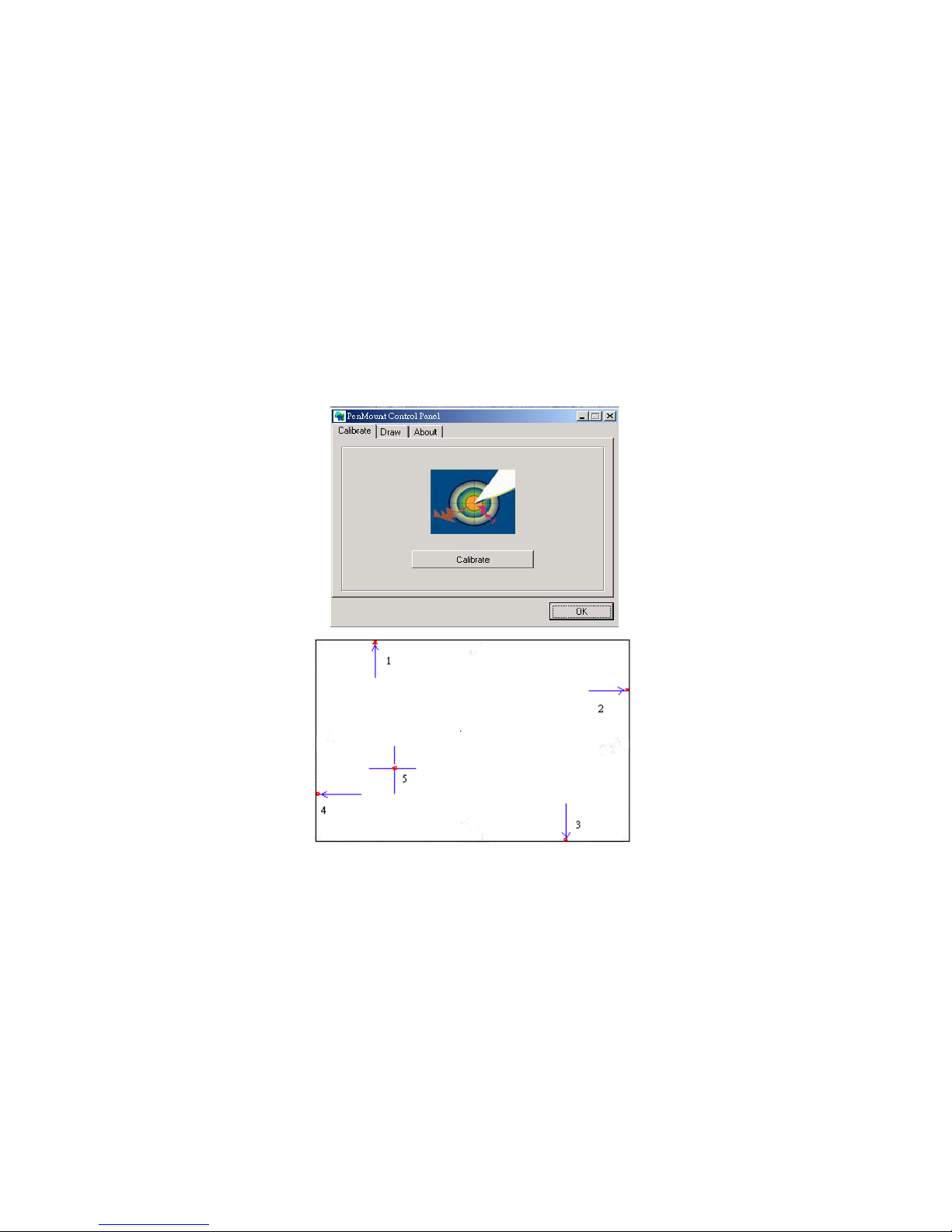
4.2 Driver Functions
4.2.1 PenMount Control Panel
Calibrate
To adjust the display with touch screen, click on Calibration and follow
the calibrate point to do calibration, there are five points on screen for
calibration.
Draw
Test or demonstrate PenMount touch screen operation, also the touch
location is shown on the display, touch DRAW to start.
14
Page 21
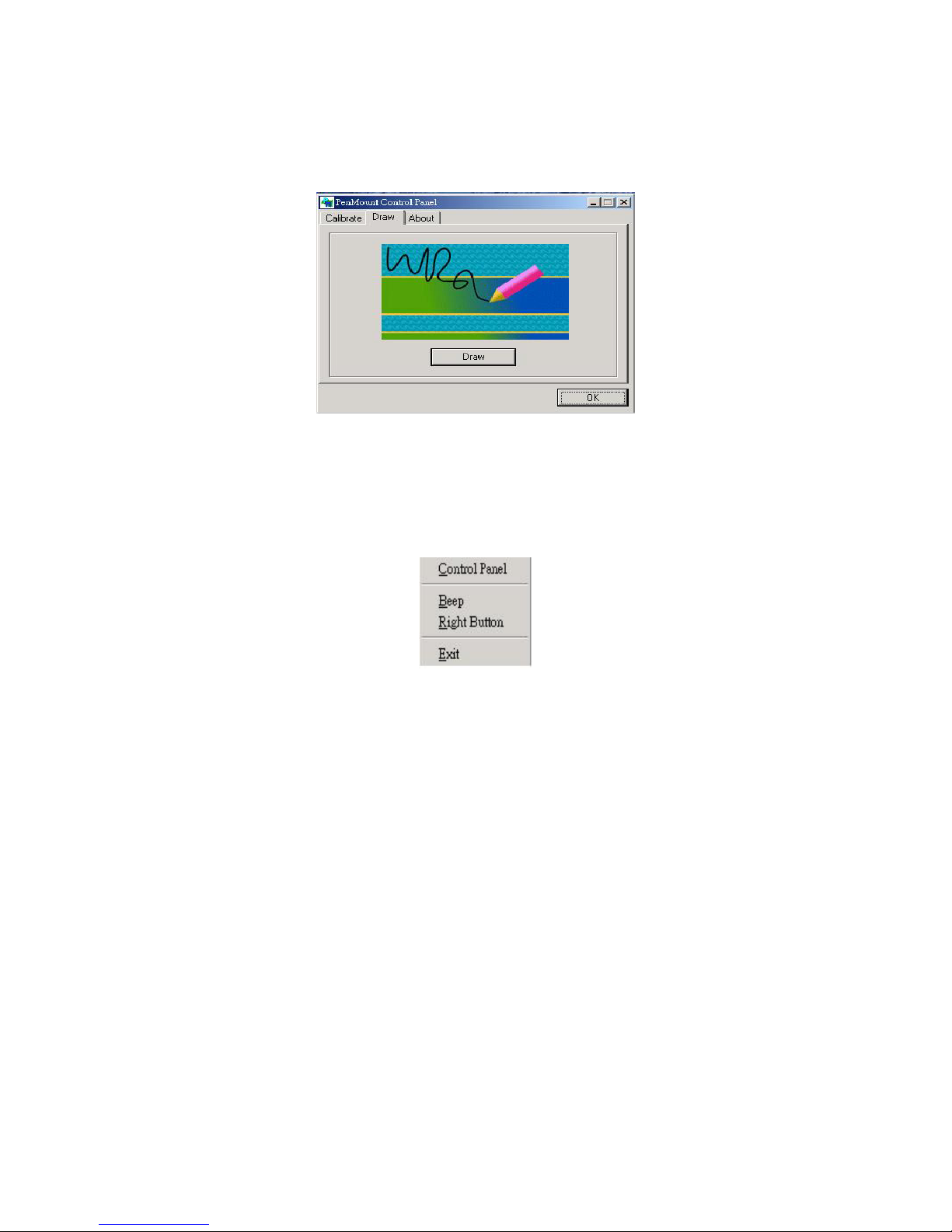
About
It shows information about PenMount controller and this driver.
4.2.2 PenMount Monitor
The PenMount monitor icon is shown in the menu bar of WIN2000
system when turn on PenMount monitor from PenMount Utilities.
There are several functions on PenMount monitor:
Right Click Button
When select this function, there is a mouse icon shown in the
right-button place of screen. It shows Left Button being as default for
normal use, touch this mouse icon to change the next touch to be Right
Button function. After one touch, the mouse icon will change to Left
Button automatically. If user needs to use right button again, user has
to touch the mouse icon again for changing the button function.
Beep
Turn on or off beep sound.
Exit
Close the PenMount Monitor function.
15
Page 22

This page intentionally left blank.
16
 Loading...