

Page 1
Computer Setup Procedure
Use this procedure to set up your IBM
compatible PC for communication with the
321 system console.
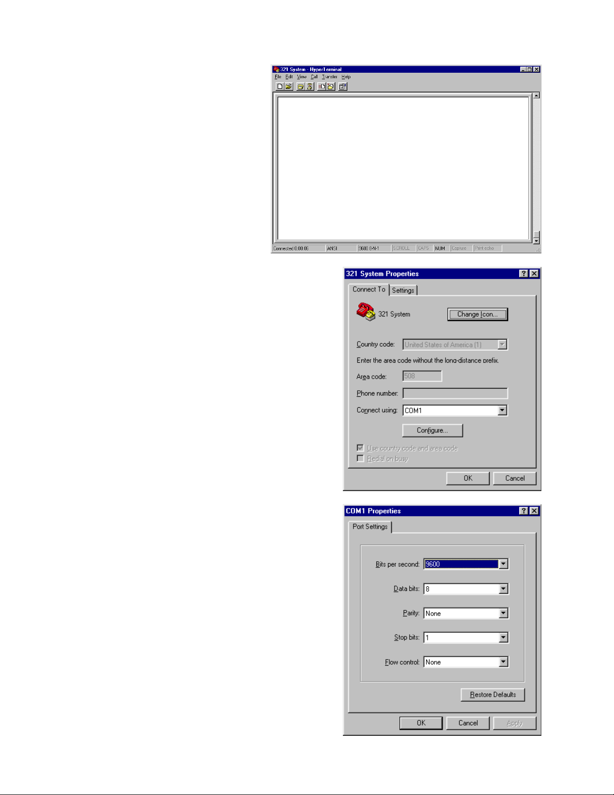
1. Open a terminal window, as shown
at right, in either Terminal or Hyperterm,
as applicable for the version of Microsoft
Windows® you are using on your PC.
2. In the terminal window, click on FILE, then
PROPERTIES. Set the properties in the
dialog box as shown at right.
®
3. In the properties dialog box shown in step
2, click on CONFIGURE to set the COM1
Properties as shown at right. Click OK to
return to the properties dialog box.
See the next page for the conclusion of this
setup procedure.
40
Page 2
Computer Setup Procedure (continued)
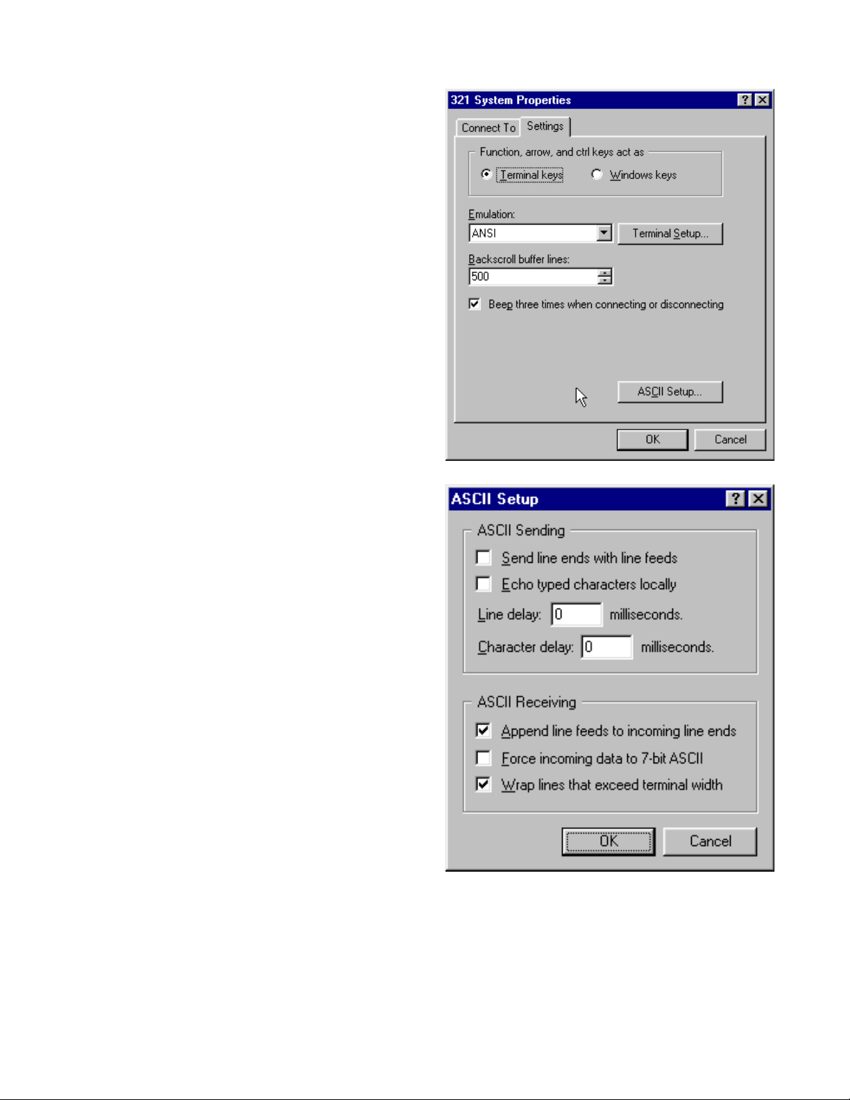
4. In the properties dialog box, click on the
SETTINGS tab and set the controls as
shown in the example at right.
Note: Be sure to check "Beep three times
when connecting or disconnecting".
5. In the properties dialog box under the
SETTINGS tab, click on the ASCII Setup
button and set the controls to look like the
example at right. Click OK to return to the
properties dialog box.
6. Once you have made all of the settings in the properties dialog box, click OK to close it. You
have now configured your PC to communicate with the 3
console under test, in the terminal window, click on CALL, then CONNECT and listen for 3
beeps. This will tell you that the PC is connected to communicate with the console. When you
have completed your session, click on CALL, then DISCONNECT to end communication with
the console.
21 system console. To connect to the
41
Page 3

Console TAP Commands
21 console can be controlled by means of test access port (TAP) commands via the
The 3
321 system TAP cable, part number 266603, from one of the computer's serial data ports to
the TAP port located on the LCD display PCB. This port can be accessed from the outside of the
console without disassembling the unit. You will need the TAP cable and a RS-232 to TTL converter, such as the B+B Electronics model 232LPTTL. You can purchase the converter online at
http://www.bb-elec.com.
The communication link for the TAP facility is:
Via a three wire TTL electrical interface (Transmit data, Receive data, Ground).
Logically inverted receive and transmit signals from RS-232 specification.
Same asynchronous character / timing construction as RS-232 specification requires.
The computer serial data port used for communication should be configured as follows:
Half-Duplex operation
9600 baud
8-bits / data character
1 stop bit
No parity
The console echoes all commands
Refer to the computer setup procedure earlier in this section for instructions.
There is no special action required to put the 3
applied TAP control may be used.
21 console does not respond to multiple commands simultaneously. The user must
The 3
receive an acknowledgement (ack) prior to issuing the next TAP command.
The tables on the following pages list the TAP commands broken down into the various subsections of console functions.
21 console into TAP mode. Once power is
42
Page 4
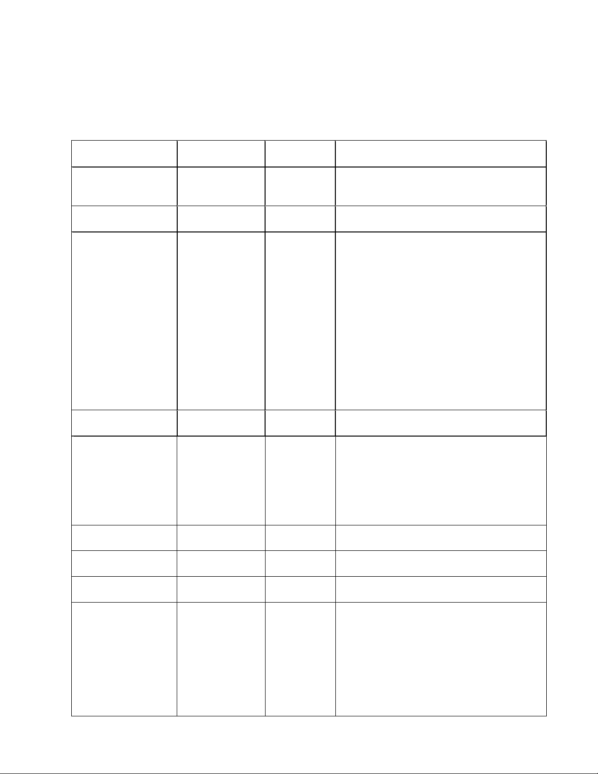
TAP Commands for control of the 3
Note: In the following tables, (\r) denotes carriage return, (b) denotes space, all other characters
are ASCII in the cases shown.
Tuner Subsystem
21 media center
Message Function Command
from External
Get Tuner Region TGTR\r Tuner
Set Tuner Region ETWR01nn\r ACK Sets tuner region nn.
Get Tuner status TUGS\r NEWLINE
Select FM Band TUFM\r ACK Subsequent Tuner functions operate on
Set Frequency TUSFdddds\r (ACK) or
Get Frequency
(AM)
Get Frequency
(FM US/Japan)
Get Frequency
(FM Europe)
Display RDS
strings
Note: This
command will work
on European units
only.
TUGF\r (ddd) or
TUGF\r (dd.d) or
TUGF\r (·dd.dd) or
TUDR\r
3-2-1
Response
region code:
nn
Jjkk
ACK
(NACK)
(dddd)
(ddd.d)
(ddd.dd)
PS data;
…ssssssss
PTY data;
…iiii
PTYN data;
…tttttttt
RT data;
…rrrrrrrr
Comments
Returns tuner region nn.
00=US, 01=Japan, 02=Europe
00=US, 01=Japan, 02=Europe
“jj’ is an ascii hex representation of the
signal strength in the form of the S-meter
reading.
“kk” is an ascii hex representation of a
byte which decodes as follows:
bits 7 through 4 are not used.
Bit 3 is stereo_strong which is 1 when the
signal is above stereo threshold.
Bit 2 is in_stereo which is 1 when in
stereo mode.
Bit 1 is RDS_present which is 1 when
RDS is present.
Bit 0 (LSB) is signal_strong which is 1
when the signal is above the stop level.
the FM band.
NACK indicates invalid frequency mddds
is an ASCII representation of frequency
(without decimal point). The left-most four
digits (mddd) are used for all settings
except FM in Europe. 06100 is 610 kHz in
AM, 10710 is 107.1 MHz in FM in the US.
10715 is 107.15 MHz in FM in Europe.
Frequency < =999 kHz
Frequency =>1000 kHz
Frequency <= 99.9 MHz
Frequency =>100.0 MHz
Frequency <= 99.99 MHz
Frequency =>100.00 MHz
Returns all RDS strings.
0 to 8 characters
0 to 16 characters
0 to 8 characters
0 to 64 characters
43
Page 5
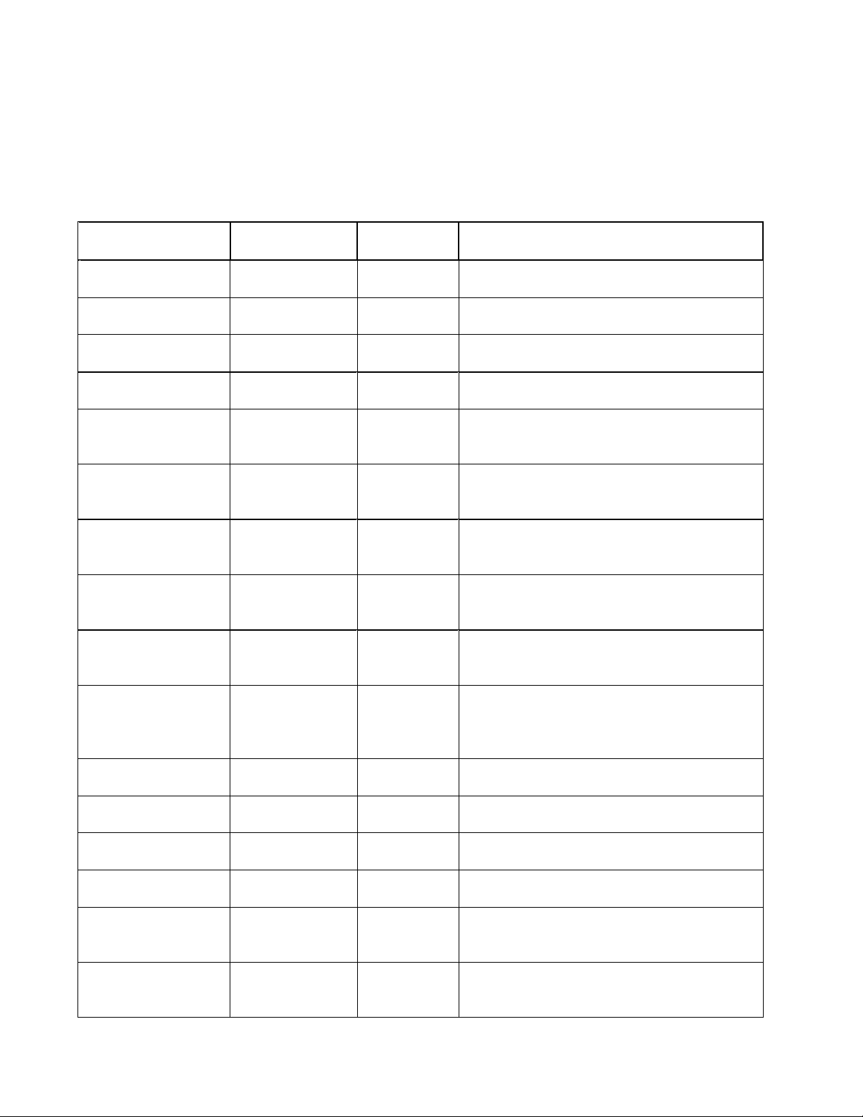
TAP Commands for control of the 3
Note: In the following tables, (\r) denotes carriage return, (b) denotes space, all other characters
are ASCII in the cases shown.
Tuner Subsystem (continued)
21 media center (continued)
Message Function Command
from External
Seek Up TUSP\r (1 SACK) or
Seek Down TUSD\r (1 SACK) or
Store AM stop level
manually
Store FM stop level
manually
Store Stereo
Threshold level
manually
Store force-mono
Threshold level
manually
Read s-meter and
store as AM stop
level
Read s-meter and
store as FM stop
level
Read s-meter and
store as stereo
threshold level
Read s-meter and
store as forcemono threshold
level.
Get AM stop level TURA\r
Get FM stop level TURF\r
Get stereo
Threshold level
Get force-mono
Threshold level
Store IF offset
–50kHz
Store IF offset
-25kHz
TUATkk\r ACK “kk” is stop level in ASCII hex 0-0xFF.
TUFTkk\r ACK “kk” is stop level in ASCII hex 0-0xFF
TUSTkk\r ACK “kk” is threshold level in ASCII hex 0-
TUMTkk\r ACK “kk” is threshold level in ASCII hex 0-
TUAR\r ACK
TUFR\r ACK
TUSR\r ACK
TUMR\r ACK
TURS\r
TURM\r kk ACK “kk” is force-mono threshold level in
TUI1\r ACK Sets IF Offset and Stores 25 kHz muliplier
TUI2\r ACK Sets IF Offset and Stores 25 kHz muliplier
3-2-1
Response
(0 SNACK)
(0 SNACK)
kk ACK
kk ACK
kk ACK
Comments
“s” is ASCII 1 if seek resulted in a station
found. “s” is ASCII 0 if no station found.
“s” is ASCII 1 if seek resulted in a station
found. “s” is ASCII 0 if no station found
0xFF.
0xFF.
“kk” is AM stop level in ASCII hex 000xFF.
“kk” is FM stop level in ASCII hex 000xFF.
“kk” is stereo threshold level in ASCII hex
00-0xFF.
ASCII hex 00-0xFF.
=
- 2
=
- 1
44
Page 6
TAP Commands for control of the 3
Note: In the following tables, (\r) denotes carriage return, (b) denotes space, all other characters
are ASCII in the cases shown.
Tuner Subsystem (continued)
21 media center (continued)
Message Function Command
from External
Store IF offset
0.00 kHz
Store IF offset
+25kHz
Store IF offset
+50kHz
Store IF offset
automatically
Get IF offset
multiplier
TUI3\r ACK Sets IF Offset and Stores 25 kHz muliplier
TUI4\r ACK Sets IF Offset and Stores 25 kHz muliplier
TUI5\r ACK Sets IF Offset and Stores 25 kHz muliplier
TUIF\r ACK Determines, sets and stores correct IF
TUGI\r TUGI·····j>
3-2-1
Response
ACK
Comments
= 0
= 1
= 2
offset multiplier automatically.
“j” is an ASCII character which is the IF
offset multiplier. (integer -2 to 2)
Audio Control Subsystem
Message
Function
Set Volume AUSVnn\r (ACK) or
Get Volume AUGV\r nn ACK “nn” hex ASCII representation of volume value.
Set Balance AUBAnn\r (ACK) or
Get Balance AUGL\r nn ACK “nn” hex ASCII representation of balance value.
Set Surround AUSSnn\r (ACK) or
Get Surround AUGS\r nn ACK “nn” hex ASCII representation of surround value.
Set Treble AUSTnn\r (ACK) or
Get Treble AUGT\r nn ACK “nn” hex ASCII representation of treble value.
Set Bass AUSBnn\r (ACK) or
Get Bass AUGB\r nn ACK “nn” hex ASCII representation of bass value.
Command
from External
3-2-1
Response
(NACK)
(NACK)
(NACK)
(NACK)
(NACK)
Comments
“nn” hex ASCII representation of volume value to
set to in 3-2-1. (00h-63h) NACK indicates invalid
value. Value represents display value of volume
only.
“nn” hex ASCII representation of balance value to
set to in 3-2-1. (+/-9) NACK indicates invalid
value.
“nn” hex ASCII representation of surround value
to set to in 3-2-1. (+/-9) NACK indicates invalid
value.
“nn” hex ASCII representation of treble value to
set to in 3-2-1 (+/-9). NACK indicates invalid
value.
“nn” hex ASCII representation of bass value to set
to in 3-2-1 (+/-9). NACK indicates invalid value.
45
Page 7
TAP Commands for control of the 3
Note: In the following tables, (\r) denotes carriage return, (b) denotes space, all other characters
are ASCII in the cases shown.
LCD Display Subsystem
21 media center (continued)
Message Function Command
from External
Disable normal
LCD output and
blank LCD
Turn on all LCD
segments and
bright backlight
Turn on LCD
diagonal test
pattern and dim
backlight
Back-light dim. LCBD\r ACK
Back-light bright. LCBB\r ACK
Back-light off. LCBF\r ACK
LCOF\r ACK
LCON\r ACK
LCPO\r ACK
3-2-1
Response
EEPROM Subsystem
Message Function Command
from
External
Write EEPROM
data and
checksums
EECS\r ACK or NACK Copies all data from mirror RAM to
3-2-1
Response
Comments
Comments
EEPROM and calculates/stores
checksums.
Note: You MUST issue this command
when setting AM and FM stop levels, FM
IF centering and FM stereo and forcemono threshold. Failure to do so will
result in your changes being lost when
power is removed.
46
Page 8
TAP Commands for control of the 3
Note: In the following tables, (\r) denotes carriage return, (b) denotes space, all other characters
are ASCII in the cases shown.
Software Subsystem
21 media center (continued)
Message Function Command
from
External
Get Main and
Display firmware
revisions
Get Main Firmware
Revision and
Checksum
Get Display
Firmware Revision
and Checksum
Get Disc drive
region information:
Firmware versions
except 01.03.01
and 51.02.06
Get Disc Drive
region information:
Firmware version
01.03.01 and
51.02.06
MMMD\r xxxxxx yyy xxxxxx is the main revision
MMMN\r MNRV321
MMDY\r DYRVrrrrcccc>
MRGN\r MRGNaabbcc
MRGN\r MRGNrffffv r = 1-6; DVD region code
3-2-1
Response
vvv>
ACK
GGHH!
Comments
yyy is the display revision
vvv is the version number.
rrrr is the ASCII representation of the
revision. cccc is the hex checksum.
aa-vendor reset = [0-4]
bb-user change = [0-5]
cc-type code =
if user = [2-5] then 1
if user = 1 then 2
if user = 0 then 3
dd = region mask
not set = FF
Region 0 = FE
Region 1 = FD
Region 2 = FB
Region 3 = F7
Region 4 = EF
Region 5 = DF
Region 6 = BF
ee = rpc scheme = 01
ffff = 1B06; last four characters of DVD
firmware version.
v = 0,1; NTSC, PAL video format.
47
Page 9
TAP Commands for control of the 3
Note: In the following tables, (\r) denotes carriage return, (b) denotes space, all other characters
are ASCII in the cases shown.
DVD Backend Subsystem
21 media center (continued)
Message Function Command
from External
Pass DVD Backend
TAP command
LXTPxx\r ACK “xx” are hex characters that signify
3-2-1
Response
Comments
Luxsonor TAP command per the following
table.
DVD Backend TAP Codes (used with LXTP command above)
0x”XX” Description
02 Test video pattern OFF.
03 Test video pattern ON.
09 Set DVD region 1
0A Set DVD region 2
0B Set DVD region 3
0C Set DVD region 4
0D Set DVD region 5
0E Set DVD region 6
80 Set default video to NTSC
81 Set default video to PAL
48
Page 10
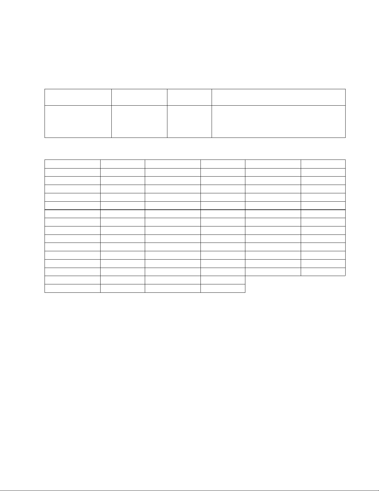
TAP Commands for control of the 3
Note: In the following tables, (\r) denotes carriage return, (b) denotes space, all other characters
are ASCII in the cases shown.
Remote Control Simulation
21 media center (continued)
Message Function Command
from External
Remote control
button simulation
REMTcc\r (ACK) or
3-2-1
Response
(NACK)
Comments
NACK indicates invalid command. cc is
the ASCII decimal representation of the
specified button (supplied with leading
zeroes) from the following table.
Remote Control Button Codes
Button Code Button Code Button Code
K_POWER 01 K_VOLDN 16 K_SEVEN 31
K_CD 02 K_MUTE 17 K_EIGHT 32
K_AUX 03 K_STPOPEN 18 K_NINE 33
K_VID1 04 K_NAVUP 19 K_MENU 34
K_VID2 05 K_NAVDN 20 K_EXIT 35
K_AM 06 K_ENTER 21 K_REWND 36
K_FM 07 K_NAVRT 22 K_FASTFW 37
K_PSPLAY 08 K_NAVLT 23 K_PAUSE 38
K_SKIPL 09 K_ZERO 24 K_EXTRA 39
K_SKIPR 10 K_ONE 25 K_NOKEY 40
K_STOP 11 K_TWO 26 K_CDMODE 41
K_PRESETUP 12 K_THREE 27 K_REPEAT 42
K_PRESETDN 13 K_FOUR 28 ANY_MODAL 43
K_SETUP 14 K_FIVE 29
K_VOLUP 15 K_SIX 30
49
Page 11
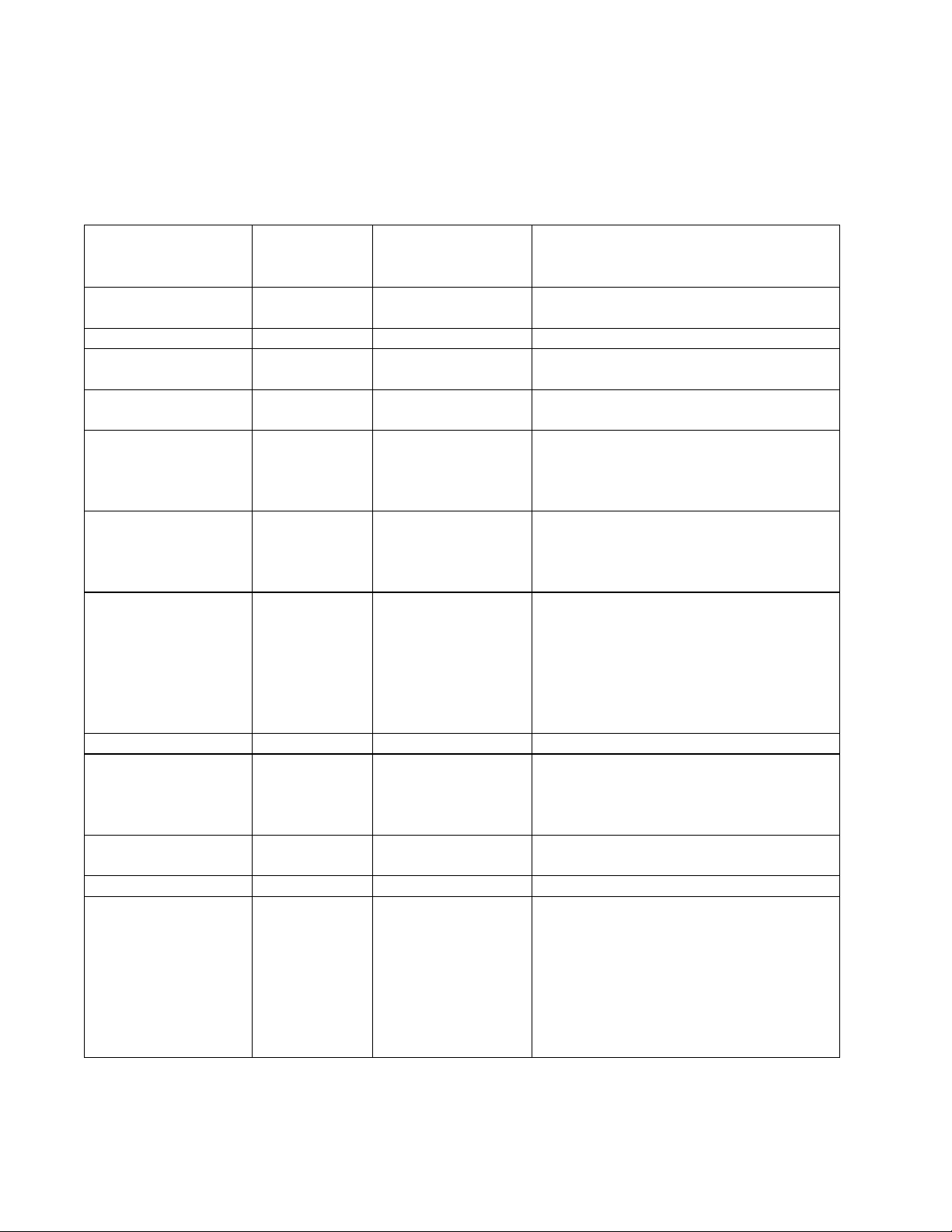
TAP Commands for control of the 3
Note: In the following tables, (\r) denotes carriage return, (b) denotes space, all other characters
are ASCII in the cases shown.
Audio Processing Subsystem
21 media center (continued)
Message Function Command
from
External
Reset the audio
DSP
Balance command BA v\r “v” is a value between –10 and 10.
Clip disable CL m\r “m” is the clip detector processing
Set Compressor
mode
Set Decoder mode DE m\r “m” is the mode. AC3 decodes AC3
Echo enable
command
Mute outputs MU c v\r “c” specifies which channel to mute.
Ooze setting OO v\r “v” is a value between –10 and 6.
Set presentation
mode
Surround balance
control
Set Surround level SL v\r “v” is a value between –10 and 6.
Source select SO c s\r “c” is the channel specified. Choices
RE\r
CO m\r “m” is either ON or OFF. A space
EC m\r “m” is the echo mode. ON echoes the
PM mm\r “mm” is the presentation mode. 4W is
SB v\r “v” is a value between –10 and 10.
3-2-1 Response Comments
mode. It is either ON or OFF.
toggles the mode.
stream, PCM decodes the PCM
stream and AUTO lets the software
select the decoder automatically.
characters out the RS-232 port. OFF
means no characters are sent out the
RS-232 port
The values are L,C,R,LS,RS,B or
ALL. “v” is either ON (muted) or OFF
(un-muted). All channels can be
controlled individually with a comma
separated string of values. The
assumed order is as above.
4 axis wide, 2W is two axis wide, 4N
is four axis narrow and 2N is two axis
narrow.
are L,C,R,LS,RS,B. “s” is the source
for the channel. Choices are D for
digital, A for analog, S for 1kHz sine,
DL for digital left, C for center, DR for
digital right, LS for left surround, RS
for right surround, LFE, AL for analog
left and AR for analog right.
50
Page 12
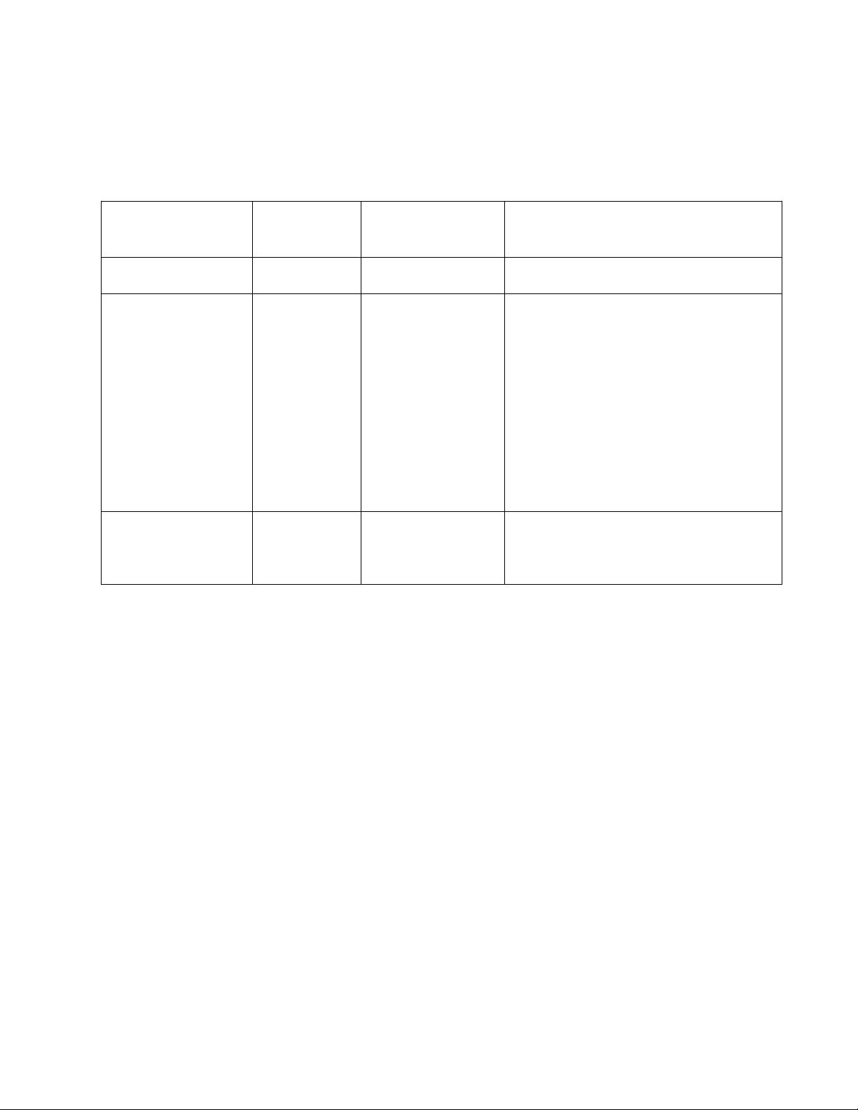
TAP Commands for control of the 3
Note: In the following tables, (\r) denotes carriage return, (b) denotes space, all other characters
are ASCII in the cases shown.
Audio Processing Subsystem (continued)
21 media center (continued)
Message Function Command
from
External
Request status
information
Set Tone controls TO c,v\r “c” is the control to be changed. The
Set volume VO c v\r “c” is the channel to be modified. The
ST\r Displays console status information.
3-2-1 Response Comments
controls are B (bass), T (treble) and
FE (film EQ). “v” is the value to set
the control to. For B and T, the value
is a number between –128 and 127.
For FE, the values can be: ON for
Film EQ on, OFF for film EQ off, BON
for bass boost from film EQ on, BOFF
which turns off the film EQ bass
boost, HON for HF cut from film EQ
on and HOFF which turns off the film
EQ HF cut.
choices are L,C,R,LS,RS,B or ALL.
“v” is the attenuation value in dB down
from maximum.
51
Page 13
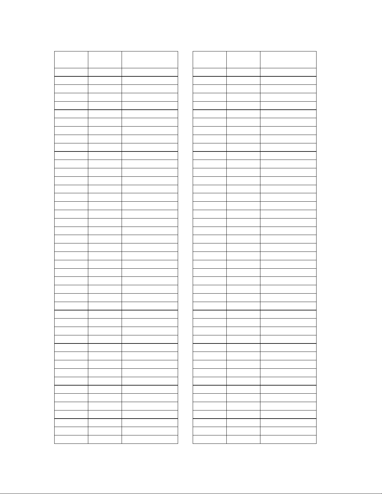
Tuner S-Meter Hexidecimal to Decimal to Voltage Conversion Charts:
HEX Decimal S-Meter
Voltage Level
0 0 0.000V
1 1 0.020V
2 2 0.039V
3 3 0.059V
4 4 0.078V
5 5 0.098V
6 6 0.117V
7 7 0.137V
8 8 0.156V
9 9 0.176V
A 10 0.195V
B 11 0.215V
C 12 0.234V
D 13 0.254V
E 14 0.273V
F 15 0.293V
10 16 0.312V
11 17 0.332V
12 18 0.352V
13 19 0.371V
14 20 0.391V
15 21 0.410V
16 22 0.430V
17 23 0.449V
18 24 0.469V
19 25 0.488V
1A 26 0.508V
1B 27 0.527V
1C 28 0.547V
1D 29 0.566V
1E 30 0.586V
1F 31 0.605V
20 32 0.625V
21 33 0.645V
22 34 0.664V
23 35 0.684V
24 36 0.703V
25 37 0.723V
26 38 0.742V
27 39 0.762V
28 40 0.781V
29 41 0.801V
2A 42 0.820V
2B 43 0.840V
2C 44 0.859V
HEX Decimal S-Meter
Voltage Level
2D 45 0.879V
2E 46 0.898V
2F 47 0.918V
30 48 0.938V
31 49 0.957V
32 50 0.977V
33 51 0.996V
34 52 1.016V
35 53 1.035V
36 54 1.055V
37 55 1.074V
38 56 1.094V
39 57 1.113V
3A 58 1.133V
3B 59 1.152V
3C 60 1.172V
3D 61 1.191V
3E 62 1.211V
3F 63 1.230V
40 64 1.250V
41 65 1.270V
42 66 1.289V
43 67 1.309V
44 68 1.328V
45 69 1.348V
46 70 1.367V
47 71 1.387V
48 72 1.406V
49 73 1.426V
4A 74 1.445V
4B 75 1.465V
4C 76 1.484V
4D 77 1.504V
4E 78 1.523V
4F 79 1.543V
50 80 1.562V
51 81 1.582V
52 82 1.602V
53 83 1.621V
54 84 1.641V
55 85 1.660V
56 86 1.680V
57 87 1.699V
58 88 1.719V
59 89 1.738V
52
Page 14
Tuner S-Meter Hexidecimal to Decimal to Voltage Conversion Charts (continued):
HEX Decimal S-Meter
Voltage Level
5A 90 1.758V
5B 91 1.777V
5C 92 1.797V
5D 93 1.816V
5E 94 1.836V
5F 95 1.855V
60 96 1.875V
61 97 1.895V
62 98 1.914V
63 99 1.934V
64 100 1.953V
65 101 1.973V
66 102 1.992V
67 103 2.012V
68 104 2.031V
69 105 2.051V
6A 106 2.070V
6B 107 2.090V
6C 108 2.109V
6D 109 2.129V
6E 110 2.148V
6F 111 2.168V
70 112 2.188V
71 113 2.207V
72 114 2.227V
73 115 2.246V
74 116 2.266V
75 117 2.285V
76 118 2.305V
77 119 2.324V
78 120 2.344V
79 121 2.363V
7A 122 2.383V
7B 123 2.402V
7C 124 2.422V
7D 125 2.441V
7E 126 2.461V
7F 127 2.480V
80 128 2.500V
81 129 2.520V
82 130 2.539V
83 131 2.559V
84 132 2.578V
85 133 2.598V
86 134 2.617V
87 135 2.637V
HEX Decimal S-Meter
Voltage Level
88 136 2.656V
89 137 2.676V
8A 138 2.695V
8B 139 2.715V
8C 140 2.734V
8D 141 2.754V
8E 142 2.773V
8F 143 2.793V
90 144 2.812V
91 145 2.832V
92 146 2.852V
93 147 2.871V
94 148 2.891V
95 149 2.910V
96 150 2.930V
97 151 2.949V
98 152 2.969V
99 153 2.988V
9A 154 3.008V
9B 155 3.027V
9C 156 3.047V
9D 157 3.066V
9E 158 3.086V
9F 159 3.105V
A0 160 3.125V
A1 161 3.145V
A2 162 3.164V
A3 163 3.184V
A4 164 3.203V
A5 165 3.223V
A6 166 3.242V
A7 167 3.262V
A8 168 3.281V
A9 169 3.301V
AA 170 3.320V
AB 171 3.340V
AC 172 3.359V
AD 173 3.379V
AE 174 3.398V
AF 175 3.418V
B0 176 3.438V
B1 177 3.457V
B2 178 3.477V
B3 179 3.496V
B4 180 3.516V
B5 181 3.535V
53
Page 15
Tuner S-Meter Hexidecimal to Decimal to Voltage Conversion Charts (continued):
HEX Decimal S-Meter
Voltage Level
B6 182 3.555V
B7 183 3.574V
B8 184 3.594V
B9 185 3.613V
BA 186 3.633V
BB 187 3.652V
BC 188 3.672V
BD 189 3.691V
BE 190 3.711V
BF 191 3.730V
C0 192 3.750V
C1 193 3.770V
C2 194 3.789V
C3 195 3.809V
C4 196 3.828V
C5 197 3.848V
C6 198 3.867V
C7 199 3.887V
C8 200 3.906V
C9 201 3.926V
CA 202 3.945V
CB 203 3.965V
CC 204 3.984V
CD 205 4.004V
CE 206 4.023V
CF 207 4.043V
D0 208 4.062V
D1 209 4.082V
D2 210 4.102V
D3 211 4.121V
D4 212 4.141V
D5 213 4.160V
D6 214 4.180V
D7 215 4.199V
D8 216 4.219V
D9 217 4.238V
DA 218 4.258V
DB 219 4.277V
DC 220 4.297V
DD 221 4.316V
DE 222 4.336V
DF 223 4.355V
E0 224 4.375V
E1 225 4.395V
E2 226 4.414V
E3 227 4.434V
HEX Decimal S-Meter
Voltage Level
E4 228 4.453V
E5 229 4.473V
E6 230 4.492V
E7 231 4.512V
E8 232 4.531V
E9 233 4.551V
EA 234 4.570V
EB 235 4.590V
EC 236 4.609V
ED 237 4.629V
EE 238 4.648V
EF 239 4.668V
F0 240 4.688V
F1 241 4.707V
F2 242 4.727V
F3 243 4.746V
F4 244 4.766V
F5 245 4.785V
F6 246 4.805V
F7 247 4.824V
F8 248 4.844V
F9 249 4.863V
FA 250 4.883V
FB 251 4.902V
FC 252 4.922V
FD 253 4.941V
FE 254 4.961V
FF 255 4.980V
54
Page 16
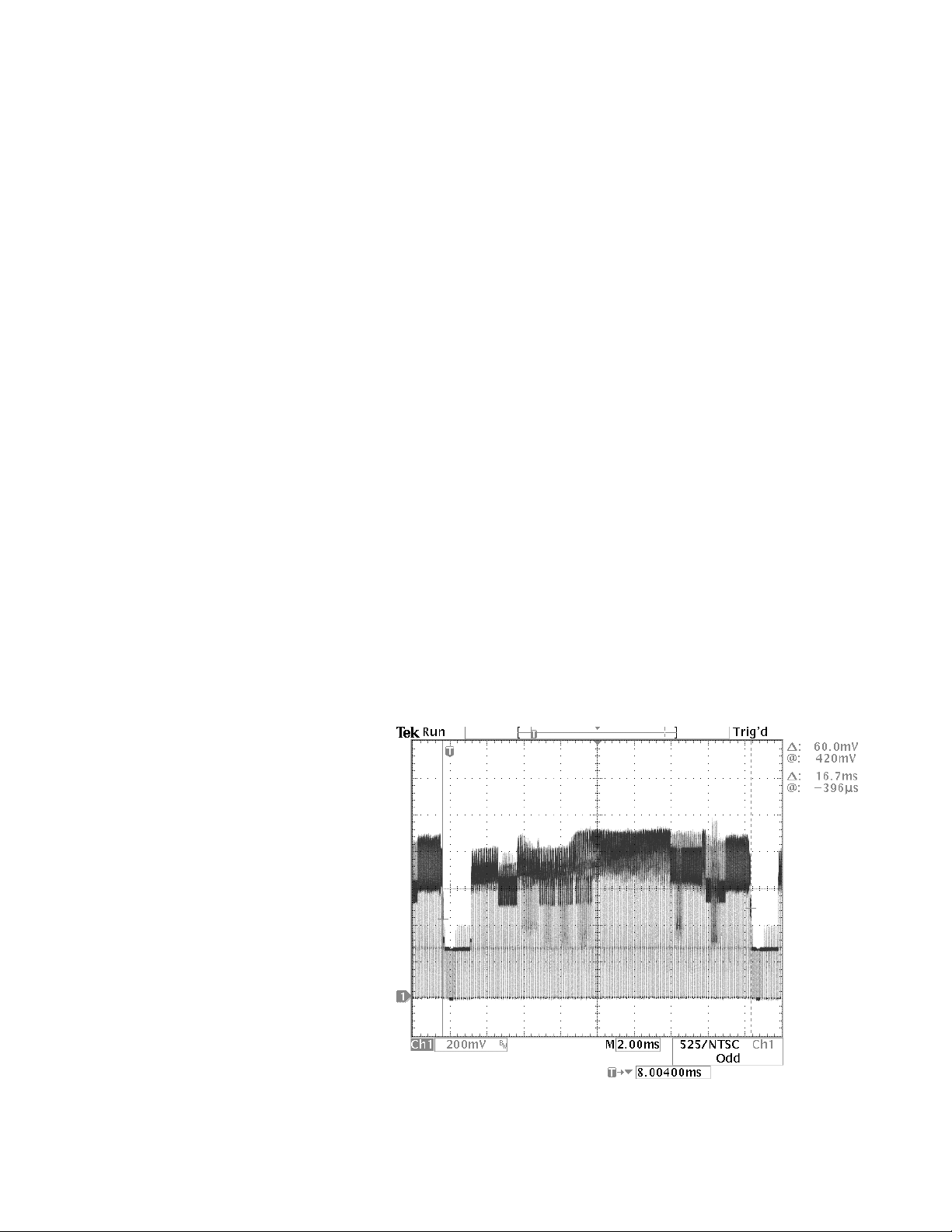
Console Main PCB Video Troubleshooting and Waveforms
Note: Refer to the 3
The video circuitry will not operate without the 27 MHz video clock signal VDO_CLK. This signal
originates at crystal Y7056 [sheet 5, B3], fed out as signal XM27HZ over to inverter U7008
[sheet 5, B1] and output as signal DX27MHZ. This clock signal is then sent over to pin 202 of the
DVD decoder IC U3000 [sheet 12, B/C2]. It is fed out of U3000 as the buffered 27 MHz clock
signal VDO_CLK at pin 154 [sheet 3, D6]. From there VDO_CLK is fed to the Video DAC U5000
[sheet 10, C7], input as pin 33.
The video data bitstream signals VDO-0 to VDO-7 are fed to the Video DAC from the DVD
decoder IC U3000 [sheet 3, C/D6].
The Video DAC takes the digital video bitstreams and converts them to the formats for both the
composite and S-Video outputs. Video signals are made up of Luminance (Y) information (black
and white) and Chrominance (C) information (color). Both of these signals combined make up
composite video (CV). S-Video uses the same signals, but keeps them separate until they sent
to the video monitor, resulting in better video fidelity. Combining these two signals before the
video monitor results in some overall signal degradation.
We will start by checking the waveforms coming out of the Video DAC U5000 [sheet 10, B/C/
D7]. You will need a 100 MHz oscilloscope with video triggering and a DC coupled scope probe
to get these waveforms.
21 Console schematics for the following information.
Remove the top cover of the console, the DVD drive and the casting using the console disassembly/assembly procedures in this manual. Connect the bass module to the console using the
system cable, or you can apply power using the test cable described earlier in the appendix.
Do not connect the array speakers to the console.
Apply power to the console and
set the output volume all the
way down to avoid overheating
the amplifier IC. Select the AUX
input and press SETTINGS.
This will start the video circuitry running without the need
for a DVD to be playing or a
source to be plugged into the
console.
We will check the composite
video (CV) output of the Video
DAC U5000 at pin 44 first
[sheet 10, C7]. The filter network composed of inductor
L5000 and associated components filter out any residual 27
MHz artifacts. The signal at
TP575 should look like the
wavform at right.
Composite Video Signal at TP575 from pin 44 of U5000
55
Page 17
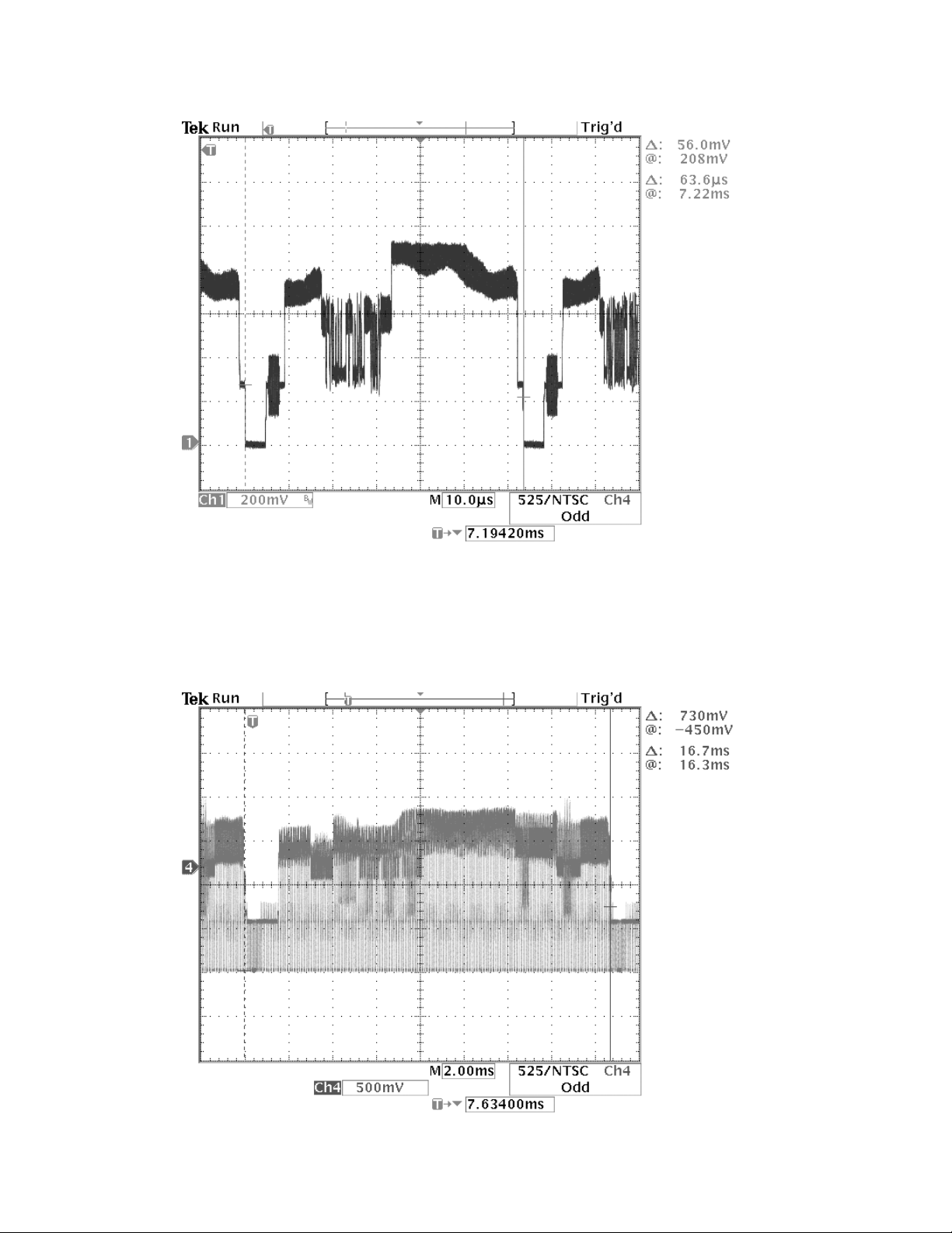
Below is the signal at TP575 again, but expanded to show the detail of the waveform.
Composite Video Signal (expanded) at pin 44 of U5000
Below is the unloaded composite video (CV) signal output which originates at pin 26 of U5001,
the A/V MUX located at grid coordinates [sheet 10, D1]. This waveform was taken at the composite video output RCA jack at J5001 on the console rear panel. You can also see it at TP684
on the main PCB.
Composite Video Signal from pin 26 of U5001 (unloaded)
56
Page 18
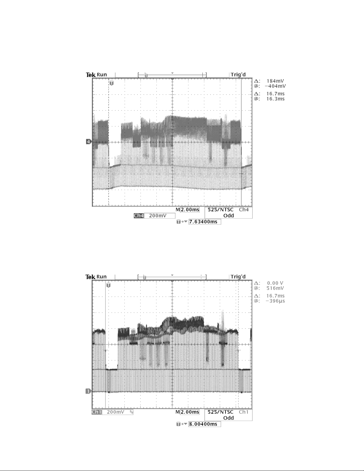
Below is the 75 Ohm loaded composite video (CV) signal output which originates at pin 26 of
U5001, the A/V MUX located at grid coordinates [sheet 10, D1]. Note that the amplitude is about
half that of the unloaded waveform on the previous page. This waveform was taken at the composite video output RCA jack at J5001 on the console rear panel.
Composite Video Signal from pin 26 of U5001 (75 Ohm load)
We will now look at the signal path for the luminance (Y) video information, which is the black
and white component of the S-Video signal. This waveform originates at the Video DAC U5000
at pin 48 (TP139).
Luminance Video Signal from pin 48 of U5000
57
Page 19
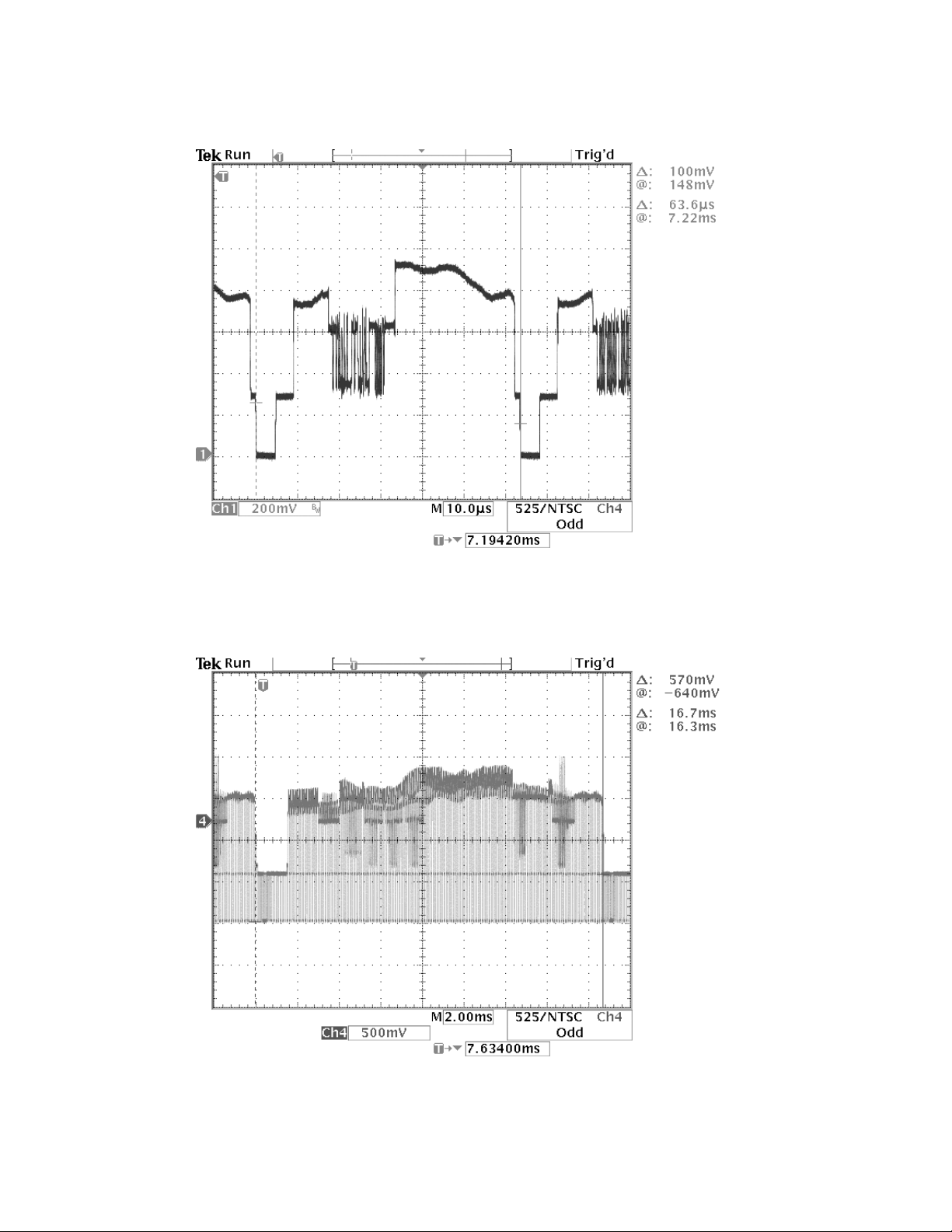
This is the same luminance (Y) video signal as the previous one, but expanded to show waveform detail. This waveform originates at the Video DAC U5000 at pin 48 (TP139).
Luminance Video Signal (expanded) from pin 48 of U5000
Below is the luminance (Y) video signal as seen at pin 3 of the S-Video output DIN jack. This is
with no load on the output. The signal originates at U5001 pin 22.
Luminance Video Signal (unloaded) S-Video DIN Connector pin 3
58
Page 20
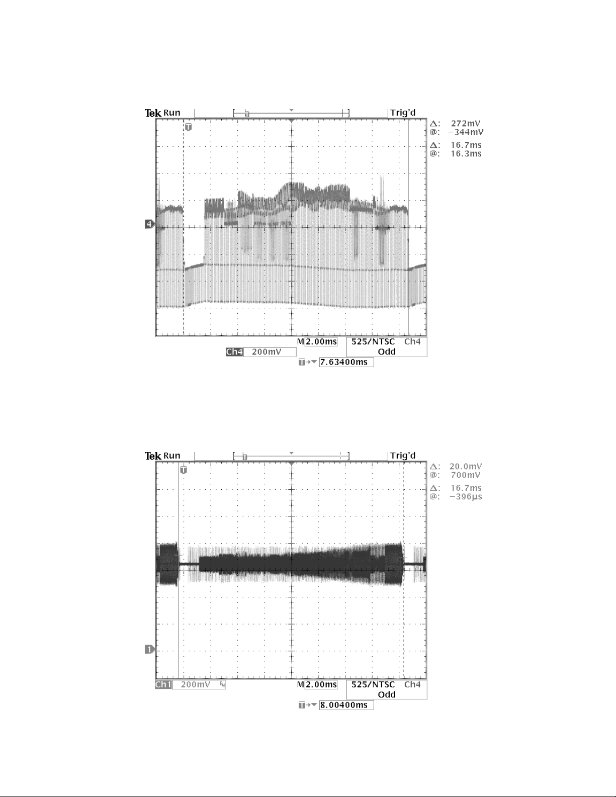
Below is the same luminance (Y) video signal as on the previous page, but with a 75 Ohm load.
It is taken at pin 3 of the S-Video output DIN jack. Note that the waveform amplitude is about half
that of the previous waveform. The signal originates at U5001 pin 22.
Luminance Video Signal (75 Ohm load) S-Video DIN Connector pin 3
We will now look at the signal path for the chrominance (C) video information, which is the color
component of the S-Video signal. The waveform below originates at the Video DAC U5000 at pin
47 (TP516).
Chrominance Video Signal at U5000 pin 47 (TP516)
59
Page 21
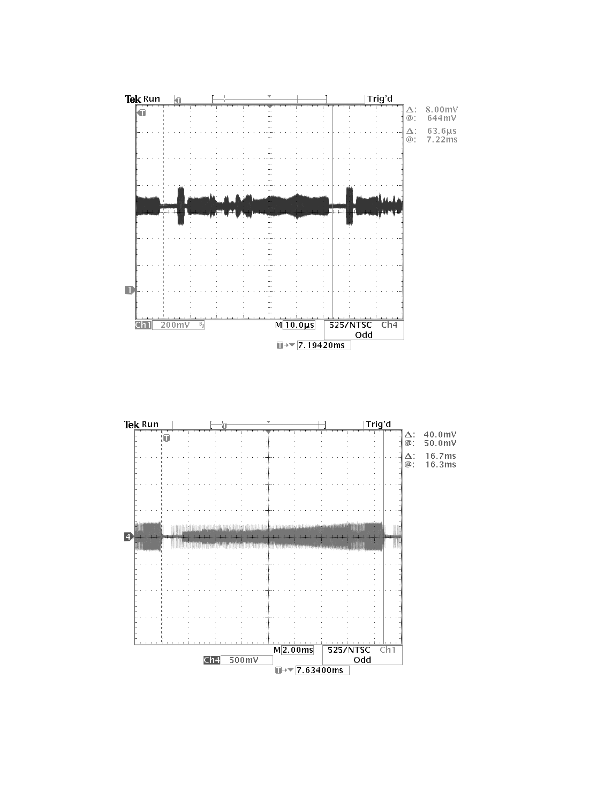
This is the same chrominance (C) video signal as the previous one, but expanded to show
waveform detail. This waveform originates at the Video DAC U5000 at pin 47 (TP516).
Chrominance Video Signal (expanded) at U5000 pin 47 (TP516)
Below is the chrominance (C) video signal as seen at pin 4 of the S-Video output DIN jack.
This is with no load on the output. The signal originates at U5001 pin 24.
Chrominance Video Signal (unloaded) S-Video DIN Connector pin 4
60
Page 22
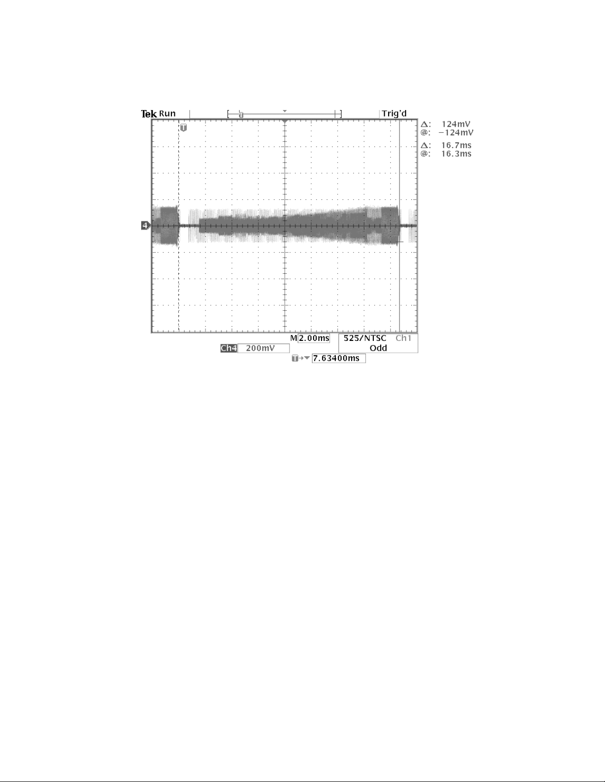
Below is the same chrominance video signal (C) as on the previous page, but with a 75 Ohm
load. It is taken at pin 4 of the S-Video output DIN jack. Note that the waveform amplitude is
about half that of the previous waveform. The signal originates at U5001 pin 24.
Chrominance Video Signal (75 Ohm load) S-Video DIN Connector pin 4
61
Page 23

Bass Module Troubleshooting Information
Note: Refer to the bass module amplifier board schematic sheet for the following information.
The bass module amplifier board uses two different ground potentials. When troubleshooting, be
careful that you are using the correct ground (reference) point. The ground point for the power
supply circuitry is at the negative (-) side of bridge BR1. When troubleshooting, be sure to
reference your tests to the negative side of BR1. Be sure to float the ground on your test equipment, including your oscilloscope. You can do this by using an 3 prong to 2 prong AC adapter
plug that does not have a ground pin. The ground reference used on the bass module is at a DC
voltage level.
This circuitry creates the +16 VDC voltage used by the console, which is seen at the positive
side of C22. The system ground point is PGND.
Common Problems:
Q1 MOSFET shorts DRAIN to SOURCE. Rarely opens. If Q1 were to short, the symptom
would be that the power supply output voltage at V (TP5) would be
used by the console and could cause distortion at high volume levels or the console to shut
down, or both.
> 22 Vdc. This voltage is
Q2 and Q3 fail. PNP transistors short and open. Sometimes need to replace both at the same
time instead of one at a time.
U1 Power amplifier. TDA7396 fails.
ZR1 16 V Zener diode fails. Zener ZR1 controls the turn on / turn off of Q2, Q3 and Q1.
BR1 Bridge rectifier fails.
Changing the 321 Console Region Code
Note: You can only change the region code for a console a total of 4 times. After that the console
will set the region code to the last one changed to permanently.
1. Connect the B+B RS-232 to TTL converter to one of the serial data ports on the back of your
IBM compatible PC. Connect the TAP interface cable, part number 266603, to the B+B converter. Plug the other end of the cable into J1 of the 3-2-1 console display board. This connector
can be accessed from outside the cabinet, under the right side of the front of the console.
2. Set up your computer as shown in the computer setup procedure in the appendix of this
manual.
3. Power up the 3
up using the computer setup procedure. Open the connection between the PC and the console.
4. On the console, place a DVD disc of the region that you want to change to into the console
tray. For example, if you wanted to change a region code 1 console to region 2, you would place
a region code 2 DVD disc into the console. Let the disc spin up. The display will read "loading".
21 system console. On the PC, open the terminal window that you have set
62
Page 24
Changing the 321 Console Region Code (continued)
5. On the PC, type in the applicable TAP command from the table below and press ENTER on
the keyboard. The region code will have changed to the new region. See the table below.
Regions Covered Region
Code
U.S., Canada, Puerto Rico 1 LXTP09 MRGN04xx01FE01
Europe, Middle East, Japan 2 LXTP0a MRGN04xx01FD01
Southeast Asia, Hong Kong, Taiwan 3 LXTP0b MRGN04xx01FB01
Central America, Mexico, South America,
Australia, New Zealand
Russia, Africa (except Egypt and South Africa),
India, Pakistan
China 6 LXTP0e MRGN04xx01DF01
Table 1. Region Code Tap Commands and Responses
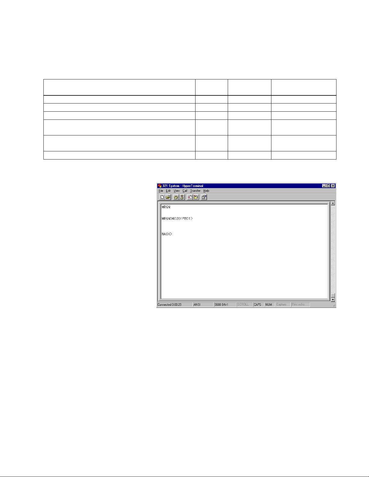
You can check to see what
region code your console is set
to by typing in the MRGN
command in the terminal window. The console will respond
with a message similar to the
one at right.
At right you will see that the
console has responded
MRGN040201FE01. The first
two characters after the MRGN
are 04, and they indicate the
number of times that the drive
manufacturer can reset the
drive. It will almost always be
04. The next two characters are
the number of times remaining
that a service center can reset the region code. In this example there are two more changes (02)
remaining. The next two characters (01) are the type code, which indicates the status of the
drive: 00 = no drive region set; 01 = drive region set; 02 = drive region set /w additional restrictions (last chance), 03 = drive region has been set permanently. This number increments when
the drive approaches the last time it can be changed before it is set permanently to the selected
region. The next two characters are an eight bit hexidecimal representation of the region that the
drive is currently set to. In the example, the FE corresponds to region 1. The other regions are
listed in the table above. The last two characters are for the CSS encryption. For all units in the
field, these two characters will always be 01.
4 LXTP0c MRGN04xx01F701
5 LXTP0d MRGN04xx01EF01
Command MRGN Command
Response
63
Page 25
Parental Control Information
The parental control circuitry prevents unauthorized viewing of DVDs above a user specified
setting. The user is required to set a four number password for DVDs with ratings above the
rating set by the user. If a user forgets what his four number password is, he/she will not be able
to view movies above the set rating. If a customer has forgotten his password, there is a generic
password that can be used to bypass the lock-out. The password is BOSE (2673), as spelled on
a telephone. Once the original password has been bypassed, the customer can set a new one.
The parental control settings used in the 3-2-1 Home Entertainment System are from 1 to 8, with
8 being the lowest security and 1 the highest. See the table below for an listing of the settings
and how they correspond to the various Motion Picture Association of America (MPAA) ratings.
DVD Rating General Description of Rating MPAA Rating
8 Unrated (generally most restricted)
7 Adult audiences NC-17
6 Mature audiences R
5 Mature teenage audiences
4 Teenage audiences PG-13
3 Mature young audiences PG
2 Most audiences
1 General (unrestricted audiences) G
Table 2. 321 Console DVD Parental Control Rating Codes
Console Display Test
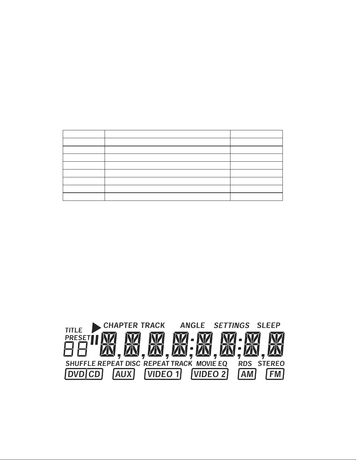
Using this procedure, you will be able to verify that all of the console LCD elements work properly by lighting all of them at once. Use the following steps.
1. Remove AC mains power to the bass module.
2. Re-apply AC mains power to the bass module. Within 10 seconds of re-applying power, press
the right hand three buttons on the top of the console at the same time. All of the LCD display
segments should light as shown in the figure below.
Note: The RDS segment is used on European models only.
64
 Loading...