

Page 1
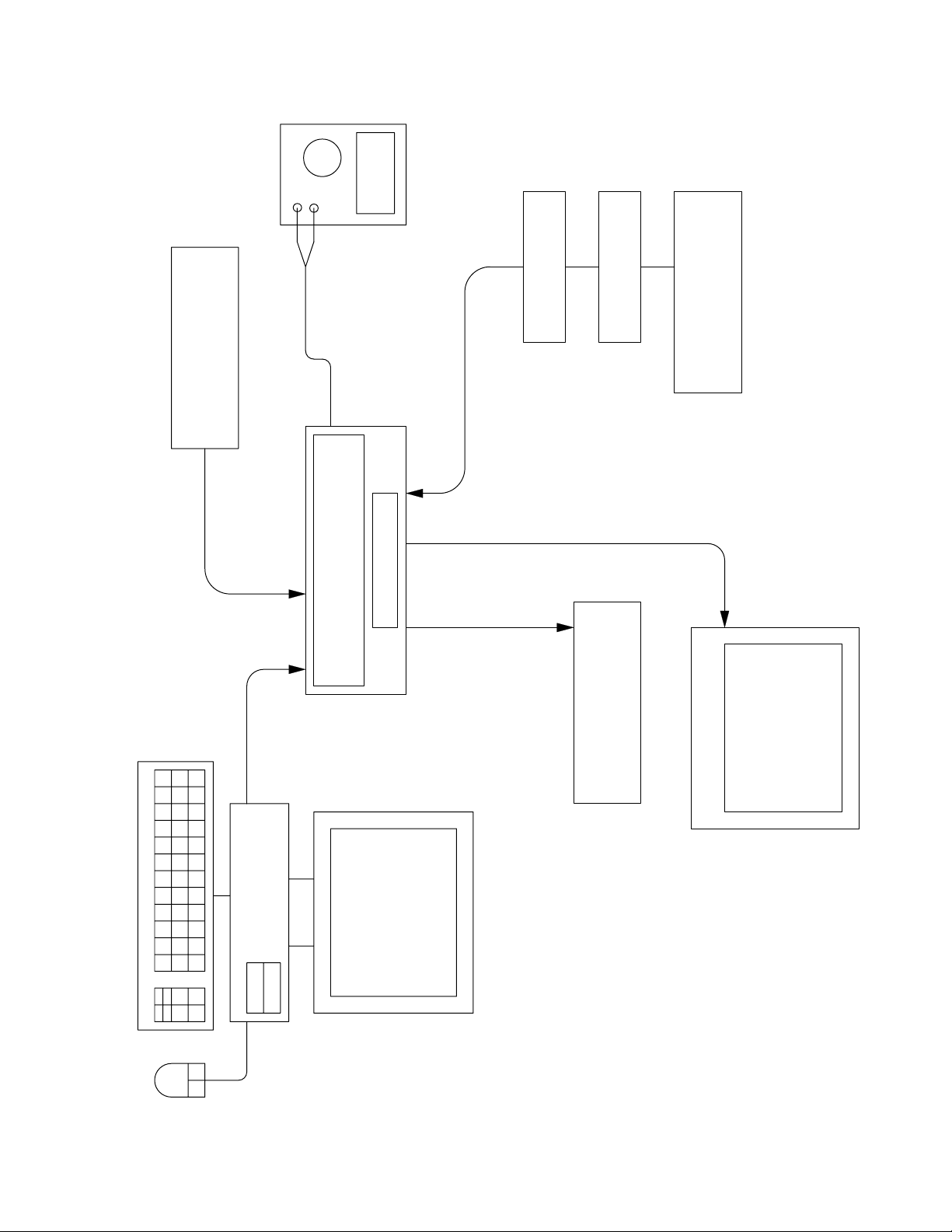
DC power
supply
+15V
RF Signal
Generator
RF input
TAP cable
Console DC power
test cable
3-2-1 Console
Optical converter
SPDIF
or Optical
input
Audio output
SPDIF converter
Audio,
dB meter
Audio Signal
Generator
or S-Video
input
Monitor
Composite
Video
compatible
PC
Figure 2. 321 Console Test Setup Diagram
IBM
23
Page 2
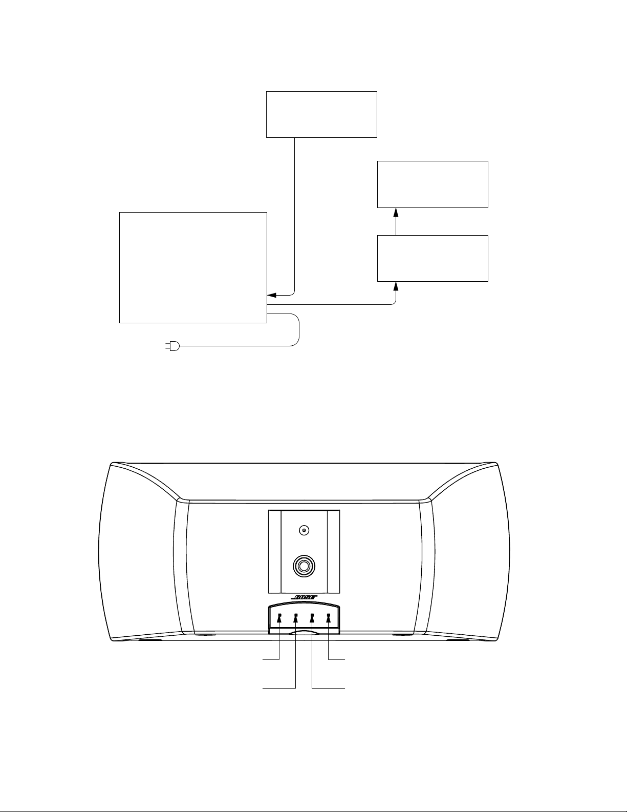
test cable
Bass Module
AC mains cable
Bass
module
Audio signal
generator
Distortion
meter
dB meter
Figure 3. 3
Driver 1 + terminal
Driver 1 - terminal Driver 2 - terminal
21 Bass Module Test Setup Diagram
Driver 2 + terminal
Figure 4. 3
21 and 321 GS Satellite Speaker Wiring Diagram
24
Page 3
TEST PROCEDURES
Console Procedures
CAUTION: The DVD drive mechanism should
not be closed by pushing it shut with no power
applied to the console. Doing so could damage
the drive. It must be closed with power applied
so that the locking mechanism inside the drive
will engage properly when the drawer is
closed.
Equipment required:
Audio signal generator
Digital multimeter
Analog to S/PDIF converter
S/PDIF to optical converter
AM/FM signal generator
Video signal generator or DVD player
Abex test DVD (TDV-540A)
Video monitor
DC power supply or bass module w/cable
Composite Video cable
S-Video cable
Optical cable
Test Setup
Set up the unit under test as shown in
Figure 2 for the following tests.
1. Analog Audio Test
1.1 Apply a 1 Vrms, 1 kHz signal to the left
and right VIDEO 1 audio analog inputs.
1.2 On the console, select the VIDEO 1
input.
1.3 Measure the output level at the audio
outputs on the console rear panel. It should
be 470 mVrms
1.4 Repeat steps 1.1 to 1.3 for the VIDEO 2
and AUX audio analog inputs.
2. Coaxial Digital Audio Test
+ 10%.
2.2 Connect the output of the S/PDIF converter to the VIDEO 1 coaxial digital input.
2.3 Apply a 500 mV, 1 kHz signal to the
analog input of the S/PDIF converter.
2.4 On the console, select the VIDEO 1
source.
2.5 Measure the output level at the line
outputs on the console rear panel. It should
be 300 mVrms
2.6 Repeat steps 3.1 to 3.5 for the VIDEO 2
digital coaxial input.
2.7 Repeat steps 3.1 to 3.5 for the AUX
digital coaxial input.
3. Optical Digital Audio Test
3.1 Connect the audio signal generator to
the input of the analog to S/PDIF converter.
3.2 Connect the output of the S/PDIF converter to the input of the S/PDIF to optical
converter.
3.3 Connect the output of the optical converter to the VIDEO 1 optical input.
3.4 Apply a 250 mV, 1 kHz signal to the
analog input of the S/PDIF converter.
3.5 On the console, select the VIDEO 1
source.
3.6 Measure the output level at the line
outputs on the console rear panel. It should
be 150 mVrms + 10%.
4. Video Tests
4.1 Connect the video generator or DVD
player to the COMPOSITE VIDEO INPUT
only.
+ 10%.
2.1 Connect the audio signal generator to
the input of the analog to S/PDIF converter.
4.2 Connect the video monitor to the COMPOSITE VIDEO OUTPUT.
25
Page 4

TEST PROCEDURES
4.3 Set the video generator to display a test
pattern. If using a DVD player, load a DVD
disc into the tray and start playback.
4.4 On the console, select the VIDEO 1
source.
4.5 Confirm that the test pattern or DVD
video appears on the video monitor and that
there are no obvious video problems.
4.6 Connect the video generator or DVD
player to the S-VIDEO input only.
4.7 Connect the video monitor to the
S-VIDEO output.
4.8 Set the video generator to display a test
pattern. If using a DVD player, load a DVD
disc into the tray and start playback.
4.9 On the console, select the VIDEO 1
source.
4.10 Confirm that the test pattern or DVD
video appears on the video monitor and that
there are no obvious video problems.
5. Internal DVD Video Test
5.1 Load the test DVD into the console.
5.2 Connect the video monitor to the
S-VIDEO output of the console.
6.3 On the 3-2-1 system remote control,
press the CD/DVD button to start playback
of the DVD disc.
6.4 Verify that the audio plays.
7. CD Playability Tests
Test discs required:
ABEX TCD-714R
ABEX TCD-721R
ABEX TCD-725R
ABEX TCD-732R
Philips TS4
7.1 Insert the ABEX TCD-725R test disc
into the console CD/DVD tray.
• Play the defect tracking (interruption)
track. Verify that the track plays properly.
The nominal is a 1.0 mm defect, 0.8 mm
limit.
• Play the defect tracking (black dot) track.
Verify that the track plays properly. The
nominal is a 1.0 mm defect, 0.8 mm limit.
• Play the defect tracking (fingerprint)
track. Verfiy that the track plays properly.
The nominal is a 75 um defect, 65 um
limit.
7.2 Insert the ABEX TCD-721R test disc
into the console CD/DVD tray. Play the
defect tracking (scratch) track. Verify that
the disc plays properly. The nominal is a
1.6 mm defect, 1.0 mm limit.
5.3 On the 3-2-1 system remote control,
press the CD/DVD button to start playback
of the DVD disc.
5.4 Confirm that the test pattern or DVD
video appears on the video monitor and that
there are no obvious video problems.
6. DVD Audio Test
6.1 Load the test DVD into the console.
6.2 If necessary, connect the satellite arrays
to the 9-pin D-sub connector.
7.3 Insert the ABEX TCD-714R test disc
into the console CD/DVD tray. Play the
defect tracking (eccentric disc) track. Verify
that the disc plays properly. The nominal is a
280 um defect, 210 um limit.
7.4 Insert the ABEX TCD-732R test disc
into the console CD/DVD tray. Play the
defect tracking (warped disc) track. Verify
that the disc plays properly. The nominal is a
1.0 mm defect, 0.7 mm limit.
26
Page 5
TEST PROCEDURES
7.5 Insert the Philips TS4 test disc into the
console CD/DVD tray. Play tracks 1 through
15, verifying that each track cues up within
the test limits. Nominal is 2 seconds or less,
limit 3 seconds.
8. Laser Current Measurement Procedure
Note: The 3-2-1 system console CD/DVD
drive uses a separate laser for each medium.
You will need to perform these tests using a
CD disc to measure the CD laser current
and a DVD disc to measure the DVD laser
current.
8.1 Remove the console top cover and DVD
mechanism using Disassembly/Assembly
procedure 3.
8.2 Remove the bottom cover of the CD/
DVD mechanism to allow access to the
board.
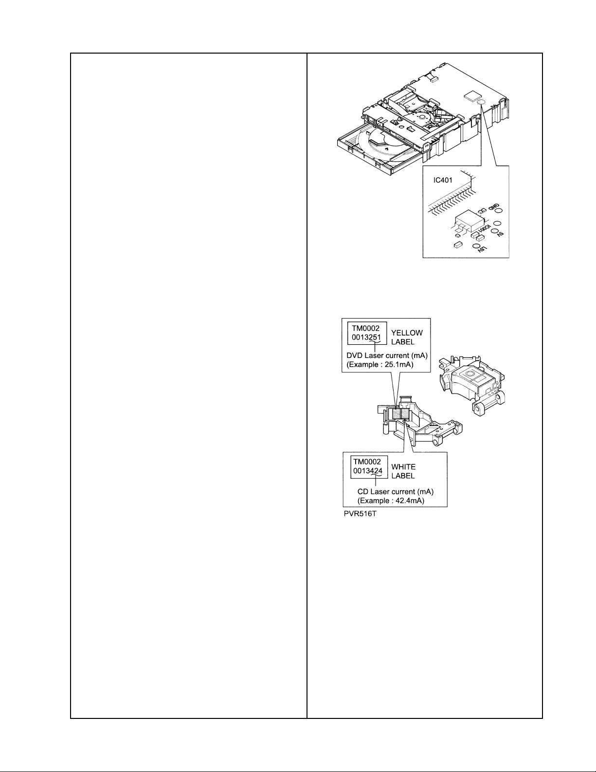
Figure 5. Laser Voltage Test Points
8.3 Connect the DVD drive to the console
using the ATAPI and DVD power extender
cables.
8.4 Insert a CD disc into the mechanism tray.
Press the PLAY button on the console.
8.5 Measure and record the voltage at the
point 5V and L5V. Be sure to use the GND
pad near the 5V and L5V points.
See Figure 5.
8.6 Subtract L5V from 5V (5V-L5V) and
record the laser voltage (LmV). LmV/1 Ohm
equals laser current (LC).
8.7 The measured laser current value should
be + 20% of the printed current rating on the
pickup head (PU). See Figure 6. If the value
is out of range, and the lens has been
cleaned, replace the DVD drive.
Figure 6. Laser Current Rating Label
8.8 Repeat steps 8.4 to 8.7 for the DVD
laser assembly.
27
Page 6
TEST PROCEDURES
3-2-1 Console Tuner Adjustments/
Measurements
The following tests can be performed without
the use of an IBM compatible PC.
AM Adjustments
For all AM alignments and tests plug the AM
antenna, part number 199824-002, into the
console and position it 2 feet away from the
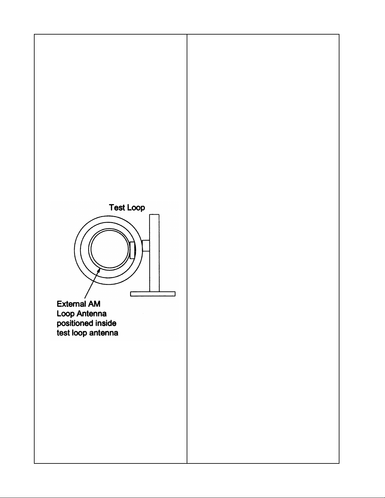
unit. Configure the AM antenna, a standard
test loop and RF generator as shown below
to create the specified field strength for each
test. The equivalent field intensity in dBuV/m
is 20 dB less than the generator output level
in dBuV EMF at the receiving antenna.
The signal levels given do not include this
factor.
10.3 Tune the console to 1500 kHz or 1503
kHz (as appropriate) and adjust the red slug
(T2004) for maximum audio level at the left
or right audio output. Verify that the level is
greater than 40 mVrms.
10.4 Change the RF frequency to 600 kHz
(US, Dual) or 603 kHz (Euro, UK, AUS and
Japan) and re-tune the console to 600 kHz
or 603 kHz (as appropriate).
10.5 Adjust the black slug (T2004) for maximum level. Verify that the level is greater
than 40 mVrms.
10.6 Repeat steps 10.2 to 10.5 until maximum audio output is obtained without the
need for further adjustment.
11. AM Sensitivity
11.1 Inject a 1080 kHz RF signal at a level
of 74 dBuV emf, 30% modulation, 400 Hz
modulation frequency.
Figure 7. AM Loop Antenna Test Setup
10. AM RF Tracking
10.1 Connect an AC meter to the AUX OUT
jacks.
10.2 Inject a 1500 kHz (US, Dual Voltage) or
1503 kHz (Euro, UK, AUS and Japan) RF
signal at a level of 90 dBuV emf, 30% modulation, 1 kHz modulation frequency.
11.2 Tune the console to 1080 kHz.
11.3 Connect a dB meter to the audio output
jacks and reference it (set to 0 dB) to the
current audio output.
11.4 Remove the AM modulation and measure the audio output jacks. The reading
should be less than -20 dB.
FM Adjustments
Note: Unless otherwise noted, set the RF
generator for 1 kHz, mono modulation, pilot
off and 75 kHz deviation. Power levels for
FM testing are given in dBf at the antenna
input to the unit.
Typically a test setup will consist of an RF
generator with a 50 Ohm output impedance
and a 50 Ohm to 75 Ohm impedance matching element. The two most commonly used
impedance matching element are a resistive
network which has a 5.7 dB insertion loss or
a “lossless” transformer which has a
0.5 dB insertion loss.
28
Page 7
TEST PROCEDURES
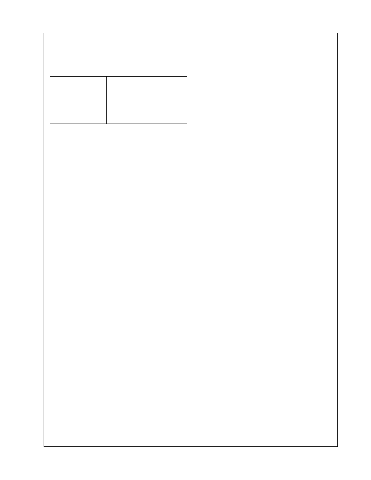
To find the required setting in dBuV emf from
a given dBf value for an RF generator with a
50 Ohm output impedance use the conversions in the following table.
Using a
“lossless”
transformer
Using a resistive
network
(5.7dB loss)
Note: For generators with RF level resolution
of only 1 dB round up.
Note: For the following FM tests, you will
need an antenna adapter cable, part number
261412, to go from an F connector to the
3.5mm connector used on the 3-2-1 console.
12. FM Distortion Measurement/Adjustment
12.1 Inject a 98.1 MHz (83.0 MHz Japan
units), RF signal at a level of 65 dBf into
J2000.
12.2 Tune the console to 98.1 MHz
(83.0 MHz Japan units).
Subtract 1.3 dB. eg:
65dBf => set generator
to 66.8 dBuV emf
Subtract 6.5 dB eg:
65dBf => set generator
to 71.5 dBuV emf
14. FM Stereo Separation
14.1 Inject a 98.1 MHz (83.0 MHz Japan
units) RF signal set to 1 kHz left only modulation with 10% pilot modulation and 75 kHz
total deviation at a level 65 dBf into J2000.
14.2 Reference a dB meter to the level at
the left audio output jack.
14.3 Switch the RF signal modulation to
right only channel.
14.4 Measure the level at the left audio
output jack. It should read -25 dB or less.
Computer Assisted Tuner Test Procedures
Additional Equipment Required:
- IBM Compatible PC
- Model 3-2-1 TAP cable, p/n 266603
- B+B Electronics RS-232 to TTL level
shifter, model 232LPTTL
Note: Refer to the computer set up instructions in the appendix for proper connection
to an IBM compatible computer.
12.3 Measure the distortion plus noise
(THD+N) at the audio output jacks. If it is
less than or equal to 0.50%, verify that the
audio level is greater than 190 mV. If these
are not the measurements you have, proceed to step 12.4.
12.4 If the THD+N is greater than 0.55%, or
the audio level is less than 190 mV, adjust
T2001 for minimum distortion. Verify that the
level is greater than 190 mV and the distortion is less than 0.55%.
13. FM Sensitivity
13.1 Inject a 98.1 MHz (83 MHz for Japan
units) RF signal at a level of 19 dBf into
J2000.
13.2 Measure the THD+N at the audio output
jacks. It should be less than or equal to
3.0%.
Refer to Figure 4, AM antenna setup diagram, to achieve the proper field strength
for the given RF generator setting.
Some of the commands will automatically
set the calibration, requiring only an external
RF signal at the input of the tuner. Other
commands require the technician to make
measurements and adjustments.
Before commencing with the tuner measurements/alignments enter the command LXOF
to disable communication between the
display microprocessor and the system
microprocessor. You should receive an ACK
(acknowledge) response on the computer’s
screen. If not then re-try until successful. To
re-enable communication enter LXON.
Note: The console's display will not change
to reflect the mode changes during tests.
29
Page 8

TEST PROCEDURES
AM Adjustments
Enter the command TUAM to switch source
to AM.
15. AM Alignment
15.1 Inject an 1500 kHz (US, Dual Voltage)
or 1503 kHz (Euro, UK, Aus and Japan) RF
signal at a level of 90 dBuV emf, 30% modulation at 1 kHz.
15.2 Enter the command TUSF15000 or
TUSF15030 (as appropriate) into the computer. This will tune the unit to 1500 kHz or
1503 kHz.
15.3 You should receive the response
“ACK>” (acknowledge) on the computer’s
screen.
Note: If you receive an error response on
the computer screen, enter the TUAM command to ensure the correct mode is selected
and re-enter the command in 15.2.
15.8 Using a non-metallic tuning tool, adjust
the black slug of T2004 for maximum output
at the audio output jacks. Verify that the level
is greater than 40 mVrms.
15.9 Repeat steps 15.1 through 15.8 until
the audio level is at a maximum without
adjustment.
16. AM Stop Level
16.1 Inject a 1080 kHz RF signal at a level
of 78 dBuV emf, 30% modulation at 1 kHz.
16.2 Enter the command TUSF10800 into
the computer. This will tune the unit to
1080 kHz.
16.3 You should receive an “ACK>”
response on the computer screen.
16.4 Enter the command TUAR. The unit will
then sample the AM S-meter level, and store
it in the EEPROM as the stop level and
return an “ACK>” response.
To verify the AM tuning frequency enter the
TUGF command to get the presently tuned
frequency. The response on the computer
screen should be "1500" or “1503“ followed
by an “ACK>”
15.4 Using a non-metallic tuning tool, adjust
the red slug of T2004 for maximum output at
the audio output jacks. Verify that the level is
greater than 40 mVrms.
15.5 Inject a 600 kHz (US, Dual Voltage) or
603 kHz (Euro, UK, Aus and Japan) RF
signal at a level of 90 dBuV emf.
15.6 Enter the command TUSF06000 or
TUSF06030 (as appropriate) into the computer. This will tune the unit to 600 kHz or
603 kHz.
15.7 You should receive an ACK response
on the computer screen.
16.5 Enter the command TURA to see the
stored level; the response on the computer
should be as follows: XX (where XX is the
stored level in hexadecimal form). Enter the
EECS command to write the new level
setting to the EEPROM before removing
power.
The current AM S-meter voltage level =
5 x (stored level in decimal) / 256. Refer to
the hex to decimal to voltage tables in the
appendix.
FM Tuner Tests
For all FM measurements and adjustments,
the RF signal is to be connected from the
signal generator to J2000 via a 50 to 75
Ohm impedance matching network.
The input levels are to be as read at the
input of J2000.
30
Page 9

TEST PROCEDURES
FM Adjustments
Enter the command TUFM to switch source
to FM.
17. FM IF Centering Adjustment
17.1 Inject a 98.1 MHz (83.0 MHz Japan
units), 1 kHz mono modulation, pilot OFF, 75
kHz deviation RF signal at a level of 50 dBf
into J2000.
17.2 Enter the command TUSF09810
(TUSF08300 Japan units) into the computer.
This will tune the unit to the appropriate
frequency.
17.3 You should receive an ACK response
on the computer screen.
Note: If you receive an error response on
the computer screen, enter the TUFM command to ensure the correct mode is selected
and re-enter the command in 17.2.
To verify the FM tuning frequency enter the
TUGF command to get the presently tuned
frequency. The response on the computer
screen should be “98.1” ("83.0" Japan units).
17.4 Enter the command TUIF into the
computer. The unit will then go through an
algorithm that determines the optimum offset
for the local oscillator (L.O.) setting to account for filter variances in the IF strip. This
offset is then stored in the EEPROM.
17.5 Enter the command TUGI to see the
stored offset; the response on the computer
should be as follows: “TUGI X >” followed
by an “ACK>” (where X is the stored offset).
The actual frequency offset of the L.O. is
this offset multiplied by 25 kHz. Valid offsets
are –1, 0 or 1. Enter the EECS command to
write the new level setting to the EEPROM
before removing power.
18. FM Distortion Measurement/
Adjustment
18.1 Inject a 98.1 MHz (83.0 MHz Japan
units), 1 kHz mono modulation, pilot OFF,
75 kHz deviation RF signal at a level of
65 dBf into J2000.
18.2 Enter the command TUSF09810
(TUSF08300 Japan units) into the computer.
This will tune the unit to the appropriate
frequency.
18.3 Measure the distortion plus noise
(THD+N) at the audio output jacks. If it is
less than or equal to 0.50%, verify that the
audio level is greater than 190 mV. If these
are not the measurements you have, proceed to step 18.4.
18.4 If the THD+N is greater than 0.55%, or
the audio level is less than 190 mV, adjust
T2001 for minimum distortion. Verify that the
level is greater than 190 mV and the distortion is less than 0.55%.
19. FM Sensitivity
19.1 Inject a 98.1 MHz (83.0 MHz Japan
units), 1 kHz mono modulation, pilot OFF,
75 kHz deviation RF signal at a level of
19 dBf into J2000.
19.2 Measure the THD+N at the audio
output jacks. It should be less than or equal
to 3.0%.
20. FM Stereo Separation
20.1 Inject a 98.1 MHz (US, Dual, Euro, UK
and Aus) or 83.0 MHz (Japan) RF signal set
to 1 kHz left only modulation with 10% pilot
modulation and 75 kHz total deviation at a
level 65 dBf into J2000.
20.2 Enter the command TUSF09810
(TUSF08300 Japan units) into the computer.
This will tune the unit to the appropriate
frequency.
31
Page 10

TEST PROCEDURES
20.3 Reference a dB meter to the left audio
output jack.
20.4 Switch the RF signal modulation to right
only channel.
20.5 Measure the left audio output jack.
It should read -25 dB or less.
21. FM Stop Level
21.1 Inject a 98.1 MHz (83.0 MHz Japan
units), 1 kHz mono modulation, pilot OFF,
75 kHz deviation RF signal at a level of
30 dBf into J2000.
21.2 Enter the command TUSF09810
(TUSF08300 Japan units) into the computer.
This will tune the unit to the appropriate
frequency.
21.3 You should receive an ACK response
on the computer screen.
21.4 Enter the command TUFR. The unit will
then sample the FM S-meter level, and store
it in the EEPROM as the stop level.
21.5 Set the RF generator for 98.9 MHz (US,
Dual Voltage), 98.3 MHz (Euro, UK, Aus) or
83.0 MHz (Japan), 1 kHz mono modulation,
pilot OFF, 75 kHz deviation RF signal at a
level of 35 dBf into J2000.
21.6 On the console, press the SEEK UP
button. Verify that the unit stops at 98.9 MHz,
98.3 MHz or 83.0 MHz as appropriate.
21.7 Set the console for 98.1 MHz (US,
Dual), 98.3 MHz (Euro, UK, Aus) or 83.0
MHz (Japan).
21.8 Set the RF generator for 98.9 MHz
(US, Dual, Euro, UK and Aus) or 83.3 MHz
(Japan), 1 kHz mono modulation, pilot OFF,
75 kHz deviation RF signal at a level of 25
dBf into J2000.
21.9 On the console, press the SEEK UP
button. Verify that the unit does not stop.
Note: You can enter the command TURF to
see the stored level; the response on the
computer should be as follows: XX (where
XX is the stored level in hexadecimal form).
Enter the EECS command to write the new
level setting to the EEPROM before removing power.
The current FM S-meter voltage level =
5 x (stored level in decimal) / 256. Refer to
the hex to decimal to voltage tables in the
appendix.
22. FM Stereo & Force Mono Threshold
22.1 Inject a 98.1MHz (83.0 MHz Japan
units) RF signal set to 1kHz stereo L=-R
modulation with 10% pilot modulation and
75 kHz total deviation at a level of 42 dBf
into J2000.
22.2 Enter the command TUSF09810
(TUSF08300 Japan units) into the computer.
This will tune the unit to the appropriate
frequency.
22.3 Enter the command TUSR. The unit will
then sample the FM S-meter level, and store
it in the EEPROM as the stereo level.
22.4 Enter the command TURS to see the
stored level; the response on the computer
should be as follows: XX (where XX is the
stored level in hexadecimal form).
22.5 Reduce the RF signal level by 2dB.
22.6 Enter the command TUSM. The unit will
then sample the FM S-meter level, and store
it in the EEPROM as the force-mono level.
Enter the command TUMS to see the stored
level; the response on the computer should
be as follows: XX (where XX is the stored
level in hexadecimal form).
FM S-meter voltage levels for each of these
settings can be calculated as per the stops
level.
32
Page 11
TEST PROCEDURES
22.7 Inject a 98.1MHz (US, Dual, Euro, UK
and Aus) or 83.0 MHz (Japan) RF signal set
to 1kHz stereo L=-R modulation with 10%
pilot modulation and 75 kHz total deviation at
a level of 45 dBf into J2000.
22.8 Enter the command TUSF09810
(TUSF08300 Japan units) into the computer.
This will tune the unit to the appropriate
frequency.
22.9 Verify that the audio output level is
> 400 mVrms. On the console display, verify
that the STEREO LED is lit.
22.10 Decrease the RF generator level to a
level of 35 dBf into J2000.
22.11 Enter the command TUSF09810
(TUSF08300 Japan units) into the computer.
This will tune the unit to the appropriate
frequency.
22.12 Verify that the audio output level is
< 10 mVrms. On the console display, verify
that the STEREO LED is not lit.
Enter the EECS command to write the new
level setting to the EEPROM before removing power.
23. FM Signal to Noise Ratio
23.1 Set the RF signal generator to 98.1
MHz (83.0 MHz Japan units), 1 kHz modulation, pilot off, 75 kHz deviation and at the
level that corresponds to 65 dBf into J2000.
23.2 Measure the output level at the left or
right audio output jack. Reference a dB
meter to this level.
Bass Module Procedures
Equipment required:
• Audio signal generator
• dB Meter
• Distortion meter
• Digital multimeter
• 2 Ohm, 50 Watt load resistor
• Bass module test cable (see instructions
in the appendix)
Test Setup
Refer to Figure 11 for the following tests.
1. Unpowered Transformer Impedance Test
1.1 On the bass module, set the AC mains
switch to the ON position (if applicable). For
the International variation, set the voltage
select switch to 115V.
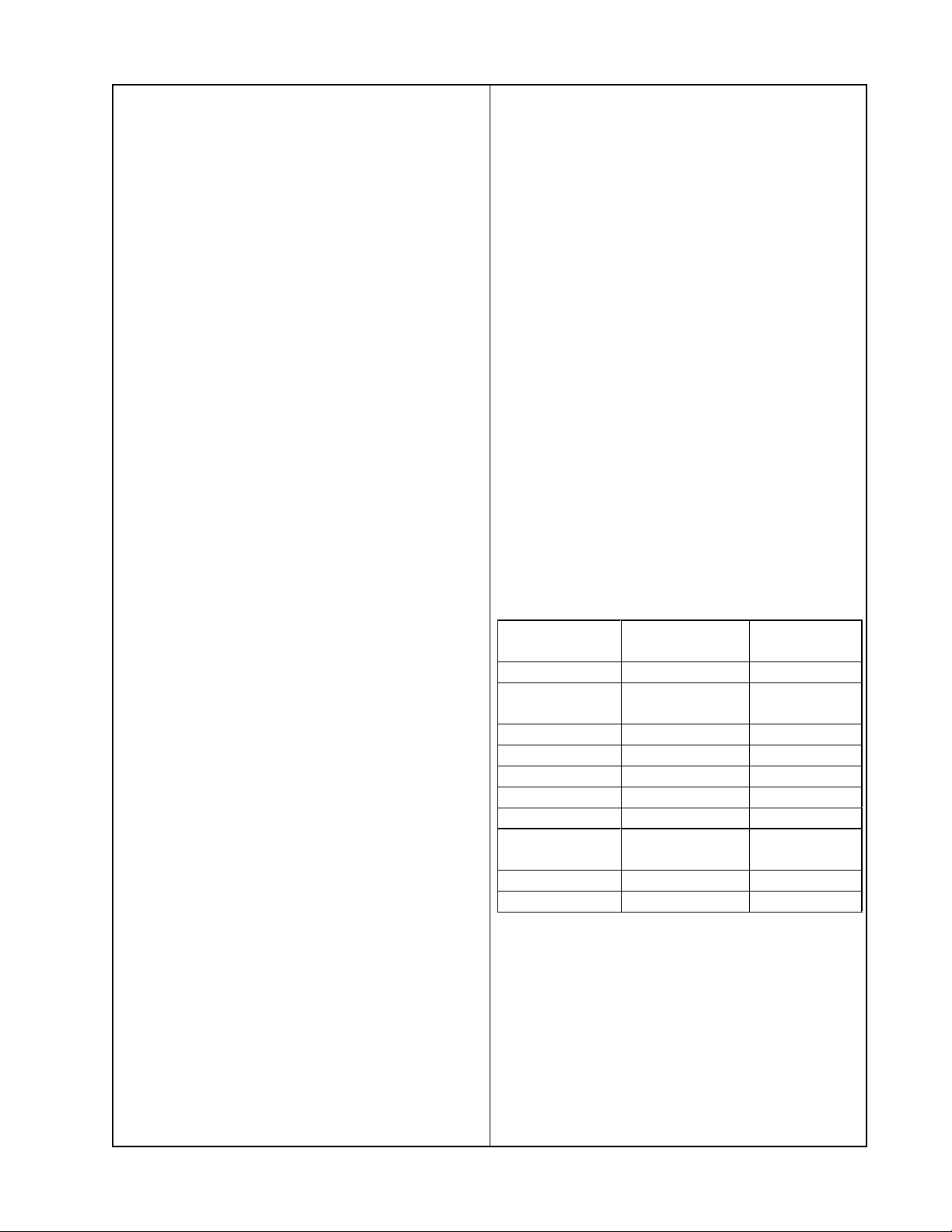
1.2 Using a DMM, measure the DC resistance of the transformer at the locations
shown in the table below.
Trans-
former
US/Canada
Euro, UK,
Aus
J5 pins 1 to 2 .121 – .164
J5 pins 4 to 5 446 – 493k
Japan
J5 pins 1 to 2 .121 – .164
J5 pins 4 to 5 446 – 493k
Dual Voltage
(S2 to 230V)
J5 pins 1 to 2 .113 – .139
J5 pins 4 to 5 446 – 493k
Measurement
location
J3 pins 1 to 2 3.14 – 4.25
J4 pins 1 to 2 8.3 – 11.3
J4 pins 1 to 2 2.9 – 4.0
J2 pins 1 to 2 8.3 – 11.3
Reading in
Ohms
23.3 Turn off the RF modulation and verify
that the level drops by > 70 dB.
33
Page 12

TEST PROCEDURES
2. Woofer DC Resistance Test
2.1 Remove the bass module rear enclosure
using bass module disassembly/assembly
procedure 1.
2.2 Remove the woofer harness from J7 on
the bass module PCB. Measure the DC
resistance of the woofer voice coil by measuring across the two pins of the woofer
harness. It should be 1.55 Ohms + 15%.
3. Power Up Test
3.1 Apply a short across BASS-EQ (J6 pin
6) and AGND (J6 pin 5). Apply 0 V (open the
SPST mute/un-mute switch on the bass
module test cable) to MUTE (J6 pin 13).
3.2 Apply AC mains voltage to the bass
module.
3.3 Measure the transformer quiescent
primary current. It should be < 250 mArms.
3.4 Measure the V supply voltage at J6 pins
7, 8, 14 and 15. It should be +16.5 + 1.0
VDC. Remove the short applied in step 3.1.
4.4 Reference a dB meter to the input level.
4.5 Measure the output gain level at J7.
It should be +26.0 dB
4.6 Measure the distortion level at J7.
It should be < 0.1%.
4.7 Apply a 0 Vdc level to MUTE at J6 pin
13 (open the SPST mute/un-mute switch on
the bass module test cable). This DC level
will mute the bass module amplifier.
4.8 Measure the mute attenuation level at
J7 relative to the input level. It should be
> 40 dB.
5. Air Leak Test
5.1 Apply a 200 mVrms, 45 Hz signal
between BASS-EQ (J6 pin 6) and AGND
(J6 pin 5).
5.2 Listen for air leaks around all cabinet
seams, joints and wire harness thru-holes.
Air leaks will be heard as a hissing or sputtering noise. Repair any air leaks. All repairs
must be hidden.
+ 2.0 dB.
3.5 Measure the J7 speaker output DC
potential on each pin of the connector relative to PGND at J6 pin 2 or 3. It should be
+ 8.2 + 1.0 Vdc.
4. Gain, Distortion and Mute Tests
4.1 Unplug the woofer harness connector at
J7 on the bass module PCB. Connect a
2 Ohm, 50 Watt load resistor to the bass
channel output to J7 on the bass module
PCB.
4.2 Apply a +5 Vdc level to MUTE at J6 pin
13 (close the SPST mute/un-mute switch on
the bass module test cable). This DC level
will unmute the bass module amplifier.
4.3 Apply a 100 mV, 100 Hz signal between
BASS-EQ (J6 pin 6) and AGND (J6 pin 5).
6. Frequency Sweep Test
6.1 Apply a 350 mVrms, 10 Hz signal be-
tween BASS-EQ (J6 pin 6) and AGND
(J6 pin 5).
6.2 Sweep the input frequency from 10 Hz
to 500 Hz. Listen for any extraneous noises
such as buzzes, rattles, ticks, port noise or
distortion.
34
Page 13

TEST PROCEDURES
Satellite Array Procedures
Notes:
• Refer to Figure 12 for the following
procedures.
• The satellite arrays are non-repairable.
The grilles can be replaced using the
disassembly/assembly procedures.
• Each satellite array contains two identical
drivers that are wired independently.
You must test each of them separately
unless otherwise specified.
1. DC Resistance Test
1.1 Using a DMM, measure the DC resis-
tance of each of the array drivers. Each
should measure 3.2 Ohms + 10%.
2. Phase Test
2.1 Remove the array grille using array
disassembly procedure 1.
2.2 Observing polarity, apply a +6 Vdc level
to one driver on the array input connector.
2.3 Observe the TwiddlerTM under test. When
the DC level is applied, the driver should
move outward. If it does, the Twiddler is wired
correctly. If not, it is wired incorrectly. Repeat
steps 2.2 and 2.3 for the other driver in the
array.
3.3 Listen for any rubbing or ticking noise
from the Twiddler. Replace any driver that is
defective.
Note: There is a normal suspension noise.
To distinguish between a rub or tick and
suspension noise, displace the cone slightly
with your finger. If the rubbing can be made
to go away or get worse, then it is a rub or
tick. If the noise stays the same, it is
suspension noise.
3.4 Repeat steps 3.1 to 3.3 for the other
driver in the array.
4. Frequency Sweep Test
4.1 Jumper both of the drivers in a single
array together. Both center pins of the array
connector are negative (-). The two outer
pins are the positive (+) pins.
4.2 Apply a 100 Hz, 3.0 Vrms signal to both
of the array drivers.
4.3 Slowly sweep the signal generator from
100 Hz to 2.0 kHz. Listen for any extraneous
noises such as buzzes, rattles, ticks, port
noise or distortion. Replace any array with
an extraneous noise that can be heard at a
distance greater than 1 foot (0.3m).
3. Air Leak Test
3.1 Apply a 180 Hz, 3 Vrms signal to one
of the Twiddler drivers in the satellite array
for 5 seconds minimum.
3.2 Listen for air leaks around all enclosure
seams, joints and the input connector. Air
leaks will be heard as a hissing or sputtering
noise. Repair any air leaks. All repairs must
be hidden.
35
Page 14
Console Main PCB troubleshooting
Disassembly
Remove the top cover of the console using
Console Disassembly procedure 1. Use the
other disassembly/assembly procedures to
remove the CD/DVD mechanism. Once that
is out of the way, remove the casting over
the main PCB. You will need to remove the
clip on the amplifier IC and to pry the amplifier IC slightly away from the heatsink before
you can remove the casting. Make sure that
the LCD display board is still connected for
troubleshooting. You will be able to power up
and troubleshoot the board while it is still in
the console base with the casting and
heatsink removed. Do not connect the 9 pin
speaker array cable to J150. Make sure the
console volume level is all the way down so
that the amplifier IC U150 does not overheat
when operated with no heatsink on it.
Test Cables
You will need several test cables in order to
be able to troubleshoot the 3
21 console
and bass module. This is for several reasons. The tuner adjustments for the console
require the use of a TAP (test access port)
cable and an IBM compatible PC. The Bose
part number for the TAP cable is 266603, and
it may be ordered through Bose Product and
Technical Support at 800-233-4408.
module also requires a test cable for test
and troubleshooting. This is a simple cable
that can be made up using the part list and
instructions on the following pages.
This cable allows you to un-mute the bass
module, apply an audio input signal, and
check the output of the power supply circuitry in the bass module. The bass module
supplies the console with its DC voltages.
Cable Extenders
21 system console uses a DVD
The 3
mechanism that is the same style as those
used in computers. You cannot operate the
console without the DVD drive connected.
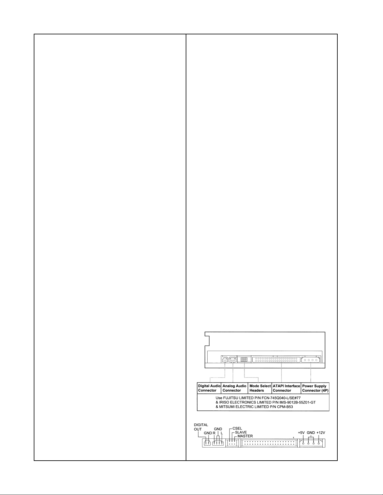
You will need to extend the 40 pin ATAPI
cable and the power cable so that you can
reach the console main PCB for troubleshooting. These parts are readily available
in any electronics or computer parts store.
Extending these cables will allow you to
troubleshoot the main PCB with the casting
removed. Observing polarity, plug one end
of the longer ATAPI cable into the main PCB.
Plug the other end of the ATAPI cable into
the back of the CD/DVD mechanism. Refer
to Figure 8. Plug one end of the extender
power supply cable into the console power
®
supply cable. Plug the other end of the
power supply cable into the power connector
on the back of the CD/DVD mechanism.
You will also need an ATAPI extender cable
and an extender power cable for the DVD
mechanism. These are used to allow the
DVD drive to be connected to the console
main PCB, yet still allow access to the PCB
for troubleshooting. The console will not
power up without the DVD drive connected
to the main PCB.
Another test cable that is useful for troubleshooting the console is a simple DC power
cable. This cable and a DC power supply will
allow you to power up and troubleshoot the
console without the bass module attached.
The part list and instructions for making this
cable are in the following pages. The bass
Figure 8. DVD Mechanism Rear Panel
36
Page 15
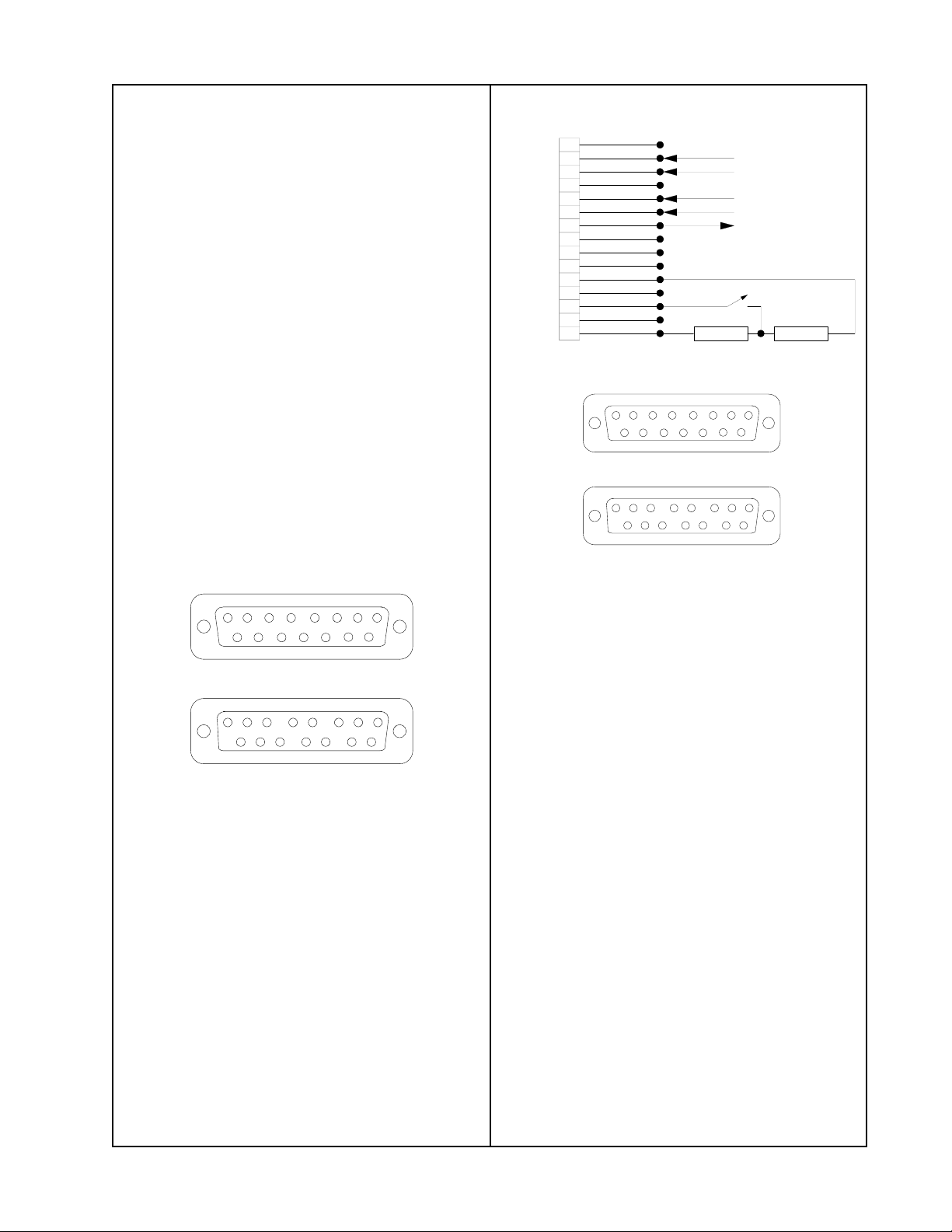
Console Power cable
You can power up the 3
21 system console
without the need for a bass module by
making up a simple cable and using a DC
power supply. The supply must be capable
of putting out +15Vdc at approximately 3A.
Parts needed:
15 pin female subminiature D connector
DC power supply
4 ft of red AWG 18 wire
4 ft of black AWG 18 wire
Bass
Module Test Cable
1
PGND
2
PGND
3
4
AGND
V+
PGND
/MUTE
V+
5
6
7
8
9
10
11
12
13
14
15
BASS EQ
15 pin D-Sub
connector
BLACK
GREEN
YELLOW
RED
WHITE
10k 5k
GND
BASS AUDIO INPUT
CABLE SHIELD
BASS AUDIO INPUT GND
BASS AUDIO INPUT
V+ OUTPUT
SPST MUTE/
UNMUTE SWITCH
1. Twist the black and red wires together to
make a twisted pair. This is to help prevent
coupling noise into the console. Strip about
1/4" of insulation from one end of each of the
wires.
2. On the rear of the 15 pin D-sub connector,
solder the red wire to pin 7 and the black
wire to pin 2. Refer to the figure below.
12345678
101112131415
9
END VIEW (FRONT)
This is the part that plugs into the 3-2-1 console
123 4
10
9
This is the part that the wires are soldered to
5678
11 12
13
REAR VIEW (BACK)
14
15
3. Strip about 1/2" of insulation from the other
end both wires. Connect the red wire to the
positive terminal and the black wire to the
ground terminal of the DC power supply.
4. Plug the 15 pin D-sub connector into the
rear panel of the 3-2-1 system console.
5. Turn on the DC power supply, and set the
output voltage for +15Vdc.
12345678
101112131415
9
END VIEW (FRONT)
This is the part that plugs into the 3-2-1 console
123 4
10
9
This is the part that the wires are soldered to
5678
11 12
13
REAR VIEW (BACK)
14
15
Figure 9. Bass Module Test Cable Wiring
Bass Module Test cable
You will need to be able to check the output
of the bass module's power supply circuitry,
as well as to input an analog audio signal to
check the bass module operation. You can
do this by making a simple test cable.
Note: The bass module will not un-mute
without +5 Vdc on the /MUTE line at pin 13.
Parts needed:
1 male 15 pin subminiature D connector
with solder terminals
1 10k Ohm, 1/4 Watt resistor
1 5k Ohm, 1/4 Watt resistor
1 ft of red AWG 18 wire
6 inches of black AWG 18 wire
4 ft of shielded twisted-pair AWG 18 wire
6 inches of white AWG 18 wire
You can now power up the 3
21 system
console without the need for a bass module.
37
Page 16
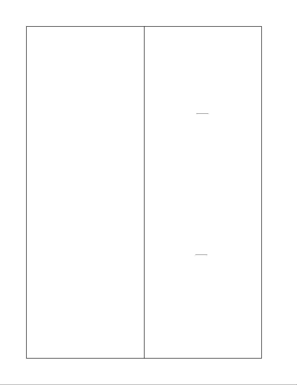
Bass Module Test cable (continued)
1. Strip and tin about 1/2" of the twisted pair
wires at one end of the twisted pair cable.
Cut the shield back about 2" at this end. At
the other end of the twisted pair cable, strip
and tin about 1/4" of the twisted pair wires.
Twist and tin about 1" of the shield. Solder the
shield to pin 3 (PGND) of the 15 pin D-Sub
connector. The shield should be grounded at
the 15 pin D-Sub connector end only. This is
to help prevent coupling noise into the
console. Solder the positive (+) lead of the
twisted pair wires to pin 6 of the 15 pin DSub connector. Solder the negative (-) of the
twisted pair wires to pin 5 of the D-Sub
connector.
2. Strip and tin about 1/4" of insulation from
one end of each of the red and black wires
and about 1/2" from the other ends. On the
rear of the 15 pin D-sub connector, solder
the red wire to pin 7 and the black wire to pin
2. The red wire at pin 7 is the +15V coming
out of the bass module power supply. This
voltage is also present on this connector at
pins 8, 14 and 15. Be careful to not short the
+15V to anything when testing. The black
wire at pin 2 is connected to PGND. Pins 4,
9, 10 and 11 are also tied to PGND.
3. Twist one end of the leads of the 10k and
5k resistors together to put them in series.
Strip and tin about 1/4" from both ends of the
white wire. Solder one end of the white wire
to the the point between the two resistors.
Solder the other end of the white wire to pin
13 on the 15 pin D-Sub connector. This pin is
where the +5 Vdc /MUTE input signal that
normally comes from the 3-2-1 console to
un-mute the bass module audio amplifier IC
U1 is brought in. The bass module will not
un-mute without this DC voltage level. Solder
the other end of the 10k resistor to pin 15 of
the D-Sub connector. Solder the other end of
the 5k resistor to pin 11 of the 15 pin D-Sub
connector. Solder a SPST switch in series
with the white wire. This is your bass module
mute/un-mute switch. When the switch is
closed, you will be applying +5 Vdc to pin 13
to un-mute the bass module.
When the switch is open, you will be applying 0 Vdc to pin 13 to mute the bass module.
21 System Date of Manufacture
3
Information
Console - The product label for the console
is located on the bottom of the unit. The date
of manufacture for the console is embedded
in the serial number on the label. The following is an example:
Ser. No. 027748C
You will notice that there are four numbers
underlined. This is the date of manufacture.
The way it is read is that the first digit underlined represents the year of manufacture.
The 1 indicates 2001.
The next three digits are the Julian date for
the day of the year. In this example that
would be the 267th day of the year.
Bass Module - The date of manufacture
information is embedded into the product
serial number in the same format as is used
for the console.
The product label for the bass module is
located on the rear of the cabinet. The following is an example:
Ser. No. 027724912420677AS
You will notice that there are four numbers
underlined. This is the date of manufacture.
The way it is read is that the first digit underlined represents the year of manufacture.
The 1 indicates 2001.
The next three digits are the Julian date for
the day of the year. In this example that
would be the 242nd day of the year.
12675109AZ
38
Page 17

Checking Console Firmware Revisions
Display PCB Firmware Procedure
The 321 console uses two separate
microprocessors, one located on the main
PCB and another located on the display
PCB.
These two versions of firmware must both
be updated when an update is performed.
The revisions of firmware for each PCB
must be compatible with each other. A listing
of compatible revisions of each firmware will
be maintained on the Bose
®
Service Operations web page at
http://serviceops.bose.com.
If one microprocessor's firmware updated
properly and the other one's didn't, then the
console may fail to operate properly.
Note: Once you have successfully checked
the firmware revision for either display PCB
or the main PCB, you can check the other
one immediately. It is not necessary to cycle
the power again between tests.
To check the display PCB firmware from the
front panel, perform the following steps:
1. Remove power from the console for at
least five seconds.
2. Re-apply power, and within five seconds,
press the EJECT, SKIP UP and SOURCE
DOWN buttons all at once for at least seven
seconds. You may see the display flashing
during this time.
3. After seven seconds, release all of the
buttons at once. You should see a display
like "03.52:7321" on the console. This example shows that version 3.52 of the display
PCB firmware is installed on this particular
console.
Main PCB Firmware Procedure
To check the main PCB firmware from the
front panel, perform the following steps:
1. Remove power from the console for at
least five seconds.
2. Re-apply power, and within five seconds,
press the EJECT, SKIP UP and VOLUME
UP buttons all at once for at least seven
seconds. You may see the display flashing
during this time.
3. After seven seconds, release all of the
buttons at once. You should see a display
like "321 247" on the console. This example
shows that version 2.47 of the main PCB
firmware is installed on this particular console.
39
 Loading...