

Page 1
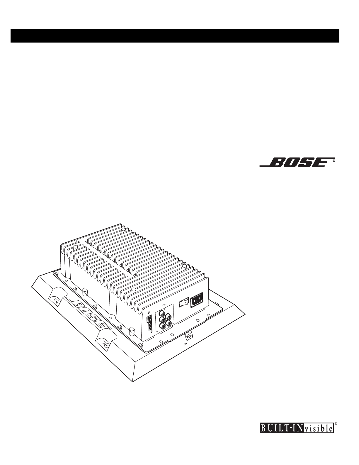
LIFESTYLE® BUILT-INvi sible® Home Theater System
TA-2
Theater Amplifier
Installation Guide
R
R
E
E
W
W
O
O
P
P
O
O
S
S
T
T
R
R
S
S
E
E
T
T
K
K
U
U
A
A
P
P
E
E
T
T
P
P
U
U
D
D
O
O
S
S
N
N
E
E
U
U
B
B
U
U
O
O
R
R
C
C
R
R
U
U
S
S
T
T
IO
IO
N
N
D
D
O
O
U
U
T
T
R
R
A
A
U
U
F
F
P
P
IN
IN
L
L
L
L
R
R
C
C
R
R
OUTPUT TO
OUTPUT TO
BASS SPEAKER
BASS SPEAKER
Home Theater System
Page 2
Safet y In formati o n
For the intended audience
This guide has been written for professional installers of
music systems or for licensed electr ici ans.
CAUTION: Onl y an experi enced contr acto r should ins tall the
BUILT-INvisible
®
home theater system from Bose. Familiarity
with standard electrical practices, as recognized by a
licensed engineer or governmental agency in your area, is
necessary. If you do not have these qualifications, do not
install the BUILT-INvisible home theater system, the system
chassis, or any other installed Bose
®
products.
CAUTION: Do not mount the ch as s i s to an uninsula ted
exterior wall or in locations where condensation may occur.
WARNING: To reduce the risk of fire or electric shock, do
not expose this system to rain or moisture.
CAUTION
RISK OF ELECTRICAL SHOCK — DO NOT OPEN
TO PREVENT ELECTRICAL SHOCK, DO NOT REMOVE
COVER. NO USER-SERVICEABLE PARTS INSIDE.
REFER SERVICING TO QUALIFIED PERSONNEL.
TO PREVENT FIRE OR SHOCK HAZARD, DO NOT
EXPOSE THIS UNIT TO RAIN OR MOISTURE.
CAUTION: Check local regulation s before instal ling or wirin g
the TA-2 theater amplifier. The building code may require
professional installation by a skilled technician or licensed
contr actor. Regional or electrical co d es may require s i mi lar
qualifications for wiring the system.
WARNING: The TA-2 theater amplifier is an electrical appliance. T here are no u s er-serviceable par ts insid e . A s with all
electr i cal appli an ces, dan gero us el ect ric al s hock may re sul t if
unqualified person ne l attempt repair. Only Bose-authorize d
personnel should perform service.
ADVERTISSEMENT : N’exposez pas ce système à la pluie
òu à l’humitit é a fin de réduire le r isqu e d ’in ce ndi e ou de choc
électrique.
AVIS
RISQUE DE CHOC ÉLECTRIQUE—NE PAS OUVRIR
AFIN DE PRÉVENIR TOUT RISQUE DE CHOC ÉLECTRIQUE,
NE PAS ENLEVER LE COUVERCLE ARRIÈRE. IL NE SE
TROUVE À L’INTÉRIEUR AUCUNE PIÈCE POUVANT
ÊTRE RÉPARÉE PAR L’UTILISATEUR. S’ADRESSER
À UN RÉPARATEUR COMPÉTENT.
AFIN DE PRÉVENIR TOUT RISQUE D’INCENDIE OU DE
CHOC ÉLECTRIQUE, NE PAS LAISSER CETTE UNITÉ À LA
PLUIE OU À L’HUMIDITÉ.
CAUTION: To reduce the risk of electric shock, do not disassemble the TA-2 theater ampl ifier chas s is. There are no userserviceable parts inside. Refer servicing to qualified service
personnel.
The CAUTION marks shown here are on the bottom end of
the chassi s .
The li g ht ning flash with arrowhead symbol, within an
equila te ral tria ngl e, al er ts the user to th e pr ese nce of
uninsulated “dangerous voltage” within the chassis
enclosure. This voltage may be sufficient to constitute a risk
of electrical shock.
The exclamation point within an equilate ral tria ngle
alert s the u s e r to the prese nce of impo rtant op erat-
ing instructions in this installer’s guide.
WARNING: To prevent electric shock do not use this plug
with an extensio n cord, re ceptacle or other ou tl et unless the
blad es ca n b e f ul ly insert ed to p r event blade expos ur e .
AVIS DE PRECAUTION : Pour réduir e le risque de choc,
ne retir ez pas l e co uvercle de ce sys tème. Il n’y a pas de
pièces pouvant être réparées par l’utilisateur à l’intérieur.
Veu illez vous adresser a des ré p ar ateurs agréés en cas de
problème.
Le avis de précaution contenus sur cette page figurent à
l’arrièr e de votre s y s tè me.
Le symbol e d ’éclair avec une tête de fl èche contenue dans un triangle équilateral a pour but d’avertir
l’utilisateur de la présence d’une “tension dangereuse” non isolee à l’intérieur de l’ébén i s teries du s ystème
qui peut être asse z haute pour causer un risq ue d e cho c
électricque.
Le point d’exclamation contenu dans un triangle
équilateral, tel qu’il apparaît sur le système, a pour
but d’avertir l’utilisateur de la présence d’instructions importantes relatives à l’utilisation et à l’entretien dans
ce mode d’emploi.
ATTENTION : Pour prevenir les chocs electriques ne pas
utilizer cette fiche polarizee avec un pro l o ng ateur, une prise
de couran t o u un e autre sort i e d e co urant, sauf s i l es l ames
peuvent etre inserees a fond sans en laisser aucune partie a
decouvrir.
2
Page 3

Impor tant Safety In st r uc ti on s
1. Read these instructions – for all components
before using this p roduc t.
2. Keep these instructions – for future reference.
3. Heed all warnings – on the product and in the
owner’s guide.
4. Follo w al l in str uc tio ns .
5. Do not use this apparatus near water or moisture – Do not use this product near a bathtub, wash-
bowl, kitchen sink, laundry tub, in a wet baseme nt,
near a swimming pool, or anywhere else that water or
moisture are present.
6. Clean only with a dry cloth – and as directed by
Bose Corporation. Unplug this product from the wall
outl et before clea ning.
7. Do not block any ventilation openings. Install in
accordance with the manufacturer’s instruc
tions – T o ensure reliable operation of the product and
to protect it from overheating, put the product in a
position and location that will not interfere with its
proper ventilation. For examp le, do not p lace t he pr o d
uct on a bed, sofa, or similar surface that may block
the ventilatio n open i ng s . Do no t put it in a bu ilt-in sys
tem, such as a bookcase or a cabine t that may keep
air from flowing thro ugh its ventil a t ion openings.
8. Do not install near any heat sources, such as
radiators, heat registers, stoves or other appa
ratus (including amplifiers) that produce heat.
9. Do not defeat the safety pur pose of the polarized or grounding-type plug. A polariz e d plug has
two blades with one wider than the othe r. A ground
ing-type plug has two blades and a third grounding
prong. The wider blade or thir d pr on g a re provided for
your safety. If the provided plug does not fit in your
outlet, consult an electrician for replacement of the
obsolete outlet.
10. Prot e ct th e po wer cord from bein g wa lk ed on or
pinched, particularly at plugs, convenience
receptacles, and the poin t where they exit from
the apparatus.
11. Only use attachments/accessories specified by
the manufacturer.
12. Use only with the cart, stand, tripod,
bracket or table specified by the
manufacturer or sold with the apparatus. When a cart is used, use caution when moving the cart/apparatus
combination to avoid injury from tip-over.
13. Unplug this apparatus during lightning storms
or when unused for long periods of time – to pre
vent damage to this product.
-
-
-
14. Refer a ll servicing to qualified service person-
nel. Servicing is required when the apparatus has
been damaged in any way: suc h as powe r-supply
cord or plug is damaged; liqui d has be en spilled or
objects have fallen into the apparatus; the apparatus
has been expos ed to ra in or mo i stu re, does no t oper
ate normally, or has been dropped – Do not attempt to
service this product yourself. Op en ing or removing
covers may expose you to dangerous vol t ag es or
other hazards. Pleas e call Bose to be referred to an
authorized service center near you.
15. To prevent risk of fire or electric shock, avoid
overloading wall outlets, ex tension cords, or
integral convenience receptacles.
16. Do not let objects or liquids en ter the product –
as they may touch dangerous voltage points or shortout parts that could result in a fire or electric shock.
17. See product enclosure bottom for safety related
markings.
18. Use proper power sources – Plug the product into
-
-
a proper power so u rce, as described in the operating
instructions or as marked on the product.
Information about products that
generate electrical noise
If applicable, this equipment has been tested and found
to comply with the limits for a Class B digital device, pursuant to Part 15 of the FC C rul es. Th ese limits are
designed to provide reasonable protection against
harmfu l inter ference in a residential installa tio n. This
equipment g enerates, uses, and can radiate radio frequency energy and, if not installed and used in accordance wit h th e ins tr uctions, may cau s e har m fu l
interferenc e to radio communicat ion s . Ho we v er, this is
no guarantee that interference will not occur in a particular installa tio n . If thi s equip ment does caus e h armful
interferenc e to radio or telev is ion reception, which can
be determined by turning the equipment off and on, you
are encourag ed to try to cor rect the in te r ference by one
or more of the following measures:
• Reorient or relocat e th e receiv ing an t en na.
• Increase the separation between the eq u ip me nt an d
receiver.
• Connect the equipment to an outlet on a different circuit than the one to which the receiver is connected.
• Consult the dealer or an experienc ed ra di o /TV technician for help.
This product complies with the Canadian ICES-003
Class B specifications.
-
-
3
Page 4
Important Safety Instructions
19. Avoi d po we r l ine s – Use extreme care when installing
an outside antenna system to ke ep from touching
powe r l ines or circu its, a s c o ntact with the m may be
fatal. Do not install external antennas near overhead
power lines or other ele ctric ligh t or power cir cuit s, nor
where an antenna can fall into such circ uits or p o wer
lines.
20. Ground all outdoor antennas – If an external antenna
or cable system is connected to this produ ct, be sure
the antenna or cable system is grounded. This will pro
vide some protection against voltage surges and builtup static charges.
Section 810 of th e N ation a l Electrical Code ANS I /
NFPA No. 70 provides information with respect to
proper grounding of the mast and supporting struc
ture, grounding of the lead-in wire to an antenna discharge unit, size of grounding conductors, location of
antenna-discharge unit, connection to grounding elec
trodes, and requirements for the ground electrode.
Refer to the antenna grounding illustration on this
page.
-
-
-
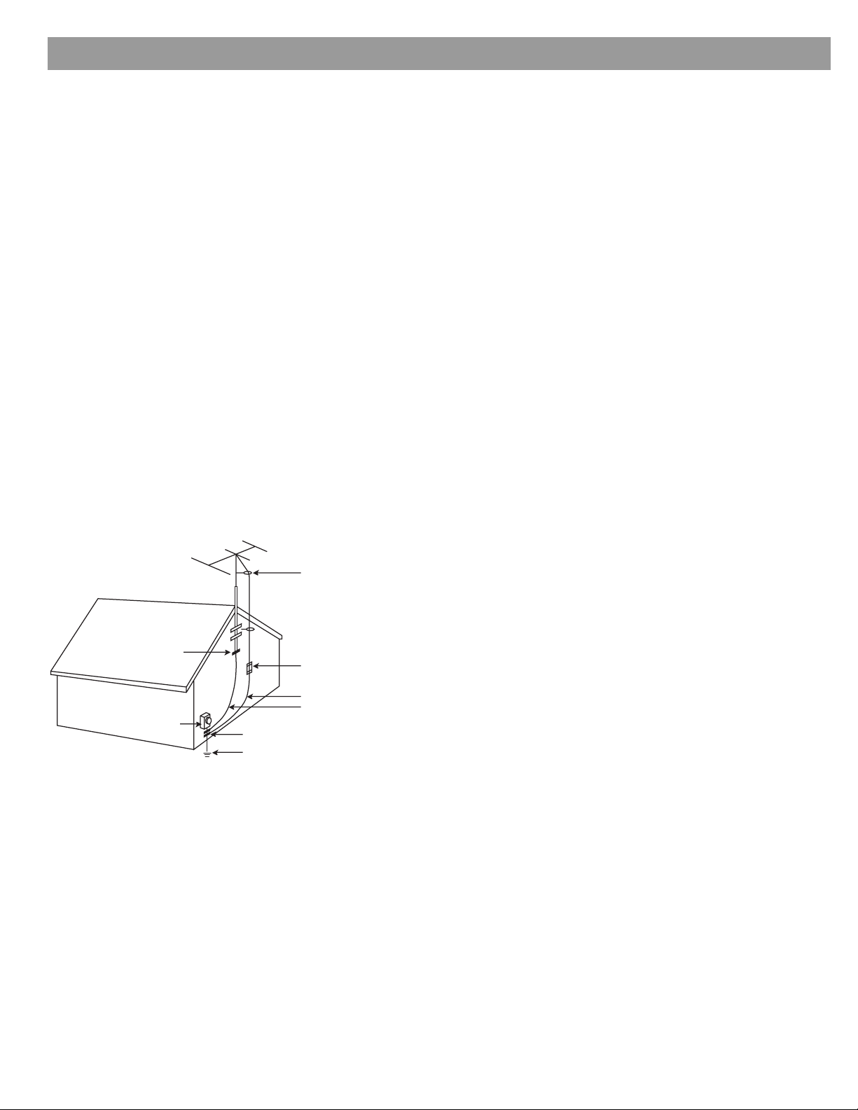
Anten na grounding
Example of antenna grounding as per N ational Electric al
Code, ANSI/NFPA 70.
Antenna lead-in wire
Ground clamp
Electric service
equipment
Ground clamps
Power service gro unding electrode
system (NEC ART 250, Part H)
Antenna discharge unit
(NEC Section 810-20)
Grounding conductors
(NEC Section 81 0-21)
Note to CATV system installer
This reminder is p rovide d to cal l the C ATV system
installer’ s attention to Article 820-40 of the NEC (of USA)
that provides guidelines for proper grounding. In particular,
it specifies that the cable ground shall be connected to the
grounding system of the building, as close to the point of
cable entry as is practica l.
4
Page 5

Where to fi nd...
Introduction . . . . . . . . . . . . . . . . . . . . . . . . . . . . . . . . . . . . . . . . . . . . . . . . . . . . . . . . . . . . . . . . . . . 6
Installation . . . . . . . . . . . . . . . . . . . . . . . . . . . . . . . . . . . . . . . . . . . . . . . . . . . . . . . . . . . . . . . . . . . . 8
Operating In formation . . . . . . . . . . . . . . . . . . . . . . . . . . . . . . . . . . . . . . . . . . . . . . . . . . . . . . . . . . . 15
Contents
The LIFESTYLE® BUILT-INvisible® TA-2 theater amplifier . . . . . . . . . . . . . . . . . . . . . . . . . . . . 6
Features and benefits . . . . . . . . . . . . . . . . . . . . . . . . . . . . . . . . . . . . . . . . . . . . . . . . . . . . . . . . 6
Connection kit . . . . . . . . . . . . . . . . . . . . . . . . . . . . . . . . . . . . . . . . . . . . . . . . . . . . . . . . . . . . . 6
Other wall plates and cables . . . . . . . . . . . . . . . . . . . . . . . . . . . . . . . . . . . . . . . . . . . . . . . . . . 7
Technical specifications . . . . . . . . . . . . . . . . . . . . . . . . . . . . . . . . . . . . . . . . . . . . . . . . . . . . . . 7
Connection panel . . . . . . . . . . . . . . . . . . . . . . . . . . . . . . . . . . . . . . . . . . . . . . . . . . . . . . . . . . . 7
Unpacking . . . . . . . . . . . . . . . . . . . . . . . . . . . . . . . . . . . . . . . . . . . . . . . . . . . . . . . . . . . . . . . . 8
Location guidelines . . . . . . . . . . . . . . . . . . . . . . . . . . . . . . . . . . . . . . . . . . . . . . . . . . . . . . . . . 8
Mounting guidelines . . . . . . . . . . . . . . . . . . . . . . . . . . . . . . . . . . . . . . . . . . . . . . . . . . . . . . . . . 8
For open wall mounting . . . . . . . . . . . . . . . . . . . . . . . . . . . . . . . . . . . . . . . . . . . . . . . . . . . 8
For mounting in an enclosure . . . . . . . . . . . . . . . . . . . . . . . . . . . . . . . . . . . . . . . . . . . . . . 9
System wiring . . . . . . . . . . . . . . . . . . . . . . . . . . . . . . . . . . . . . . . . . . . . . . . . . . . . . . . . . . . . . . 10
Speaker placement guidelines . . . . . . . . . . . . . . . . . . . . . . . . . . . . . . . . . . . . . . . . . . . . . . . . . 12
Left and right front cube speakers . . . . . . . . . . . . . . . . . . . . . . . . . . . . . . . . . . . . . . . . . . . 12
Center cube speaker . . . . . . . . . . . . . . . . . . . . . . . . . . . . . . . . . . . . . . . . . . . . . . . . . . . . . 12
Surround speakers . . . . . . . . . . . . . . . . . . . . . . . . . . . . . . . . . . . . . . . . . . . . . . . . . . . . . . . 13
Acoustimass® module . . . . . . . . . . . . . . . . . . . . . . . . . . . . . . . . . . . . . . . . . . . . . . . . . . . . 13
Troubleshooting . . . . . . . . . . . . . . . . . . . . . . . . . . . . . . . . . . . . . . . . . . . . . . . . . . . . . . . . . . . . 14
Amplifier status indicators . . . . . . . . . . . . . . . . . . . . . . . . . . . . . . . . . . . . . . . . . . . . . . . . . . . . 15
Reading the amplifier status . . . . . . . . . . . . . . . . . . . . . . . . . . . . . . . . . . . . . . . . . . . . . . . . . . . 15
©2003 Bose Corporation. No part of this work may be reproduced , modified, distributed or otherwise used without prior written permission.
Manuf actured under license f rom Dolb y Laboratories . “Dolby” and the double-D symbol ar e tradem arks of Dolby Laboratories. Con f idential
Unpublished Works. ©1992-1997 Dolby Laboratories. All rights reserved.
“DTS” and “DTS Digital Surround” are registered trademarks of Digital Theater Systems, Inc.
MPEG Layer-3 audio compression technology licensed by Fraunhofer IIS and THOMSON multimedia.
This product incorporates copyright protection technology that is protected by method claims of certain U.S. patents and other intellectual
property rights owne d b y Macrov i s i on Co rporation and other rights own ers. Use of this copyright prot ec t i on technology must be authorized
by Macrovision Corporation, and is intended for home and other limited viewing uses only unless otherwise authorized by Macrovision Corporation. Reverse engineering or disassembly i s prohi bited.
This product incorp orates copyright protecte d technology and other intelle ctual property rights owne d b y Ci rru s Logi c, Inc. and is subject to
the copyright protec tion of the U.S. as well as oth er licensing re strictions and protec tions. U se of this copyright prot ected technology is limited solely to use with the Cirrus Logic integrated circuits incorporated in this product. Reverse engineering or disassembly is prohibited.
5
Page 6

Introduction
The LIFEST YLE® BUILT-INvisible® TA-2 theater amplifier
The LIFESTYLE® BUILT-I N vis ib le TA-2 theater amp lifi e r is an amp lifier component used for
LIFESTYLE® BUILT-INvisible home theater systems. It is easily installed and can be almost
completel y hidden from view. Designed for use onl y w ith th e AV28 med ia ce nt er, the TA -2
theater ampl ifier is compatib le with combina tio ns o f 191 speakers and the var iou s cub e
speakers sold with Bose
Note: Maximum recommended room size for this system is 700 sq ft.
Figure 1
Carton contents
®
LIFESTYLE® systems.
R
R
E
E
W
W
O
O
P
P
O
O
T
T
S
S
R
R
S
S
E
E
T
T
K
K
U
U
A
A
P
P
E
E
T
T
P
P
U
U
S
S
O
O
D
D
N
N
E
E
U
U
B
B
U
U
O
O
R
R
C
C
R
R
U
U
S
S
O
O
T
T
I
I
N
N
D
D
O
O
U
U
T
T
R
R
A
A
U
U
F
F
P
P
N
N
I
I
L
L
L
L
R
R
C
C
R
R
AKER
AKER
OUTPUT TO
OUTPUT TO
BASS SPE
BASS SPE
Feature s and benefits
• Remote ope ra tio n – Allows for hidden-from-view placement.
• Includes the ADAPTiQ® audio calibration system.
• Includes digital signal processing – pr ovi de s V id eosta ge® 5 steering logic, Dolby® Digital
and DTS
• Provides dynami c ra ng e co ntrol at low volume – makes it easy to dis ce r n dialogue even
with the volume tur n ed dow n.
• Allows control integration of most video sources (TV, cable/satellite, VCR).
Connection kit
The TA-2 connection kit [PC 34245 (White), PC 34246 (Ivory)] consists of the following items:
Qty Item PC code
2 TA-2 Source/De st ination Wall Plate (doub le mini DIN) PC 33948 (White)
1 TA-2 Connection Cable (9-pin mini DIN to 8-pin RJ45) PC 33496
1 TA-2 Speaker Connection Cable (14-pin molex to 6 male RCA) PC 33495
1 TA-2 Speaker Wall Plate PC 33950 (White)
®
decoding, FilmEQ, Active EQ, Dynami c EQ, and digital bitstream proce ssing.
PC 33949 (Ivory)
PC 33951 (Ivory)
Note: All items can be purchased separately.
6
Page 7

Other wall plates and cables
Item PC code
TA-2 Source/Destinatio n Wall Pla te (si n g le mi n i DIN ) PC 34247 (White)
TA-2 Connection Cable (8-pin Terminal Block to 8-pin RJ45) PC 33946
TA-2 Speaker Connection Cable (14-pin term block to 6 male RCA) PC 33947
Technical specifications
Processing
Bose® Videostage® 5 steering logic, Dolby® Digital dec oding, DTS® decoding
Audio inputs
S/PDIF
Indicators
Amplifier status green and amber LEDs
Signal-to-noise ratio
94dB
Introduction
PC 34248 (Ivory)
Connection panel
Audio input jack (RJ45)
Microswitches
DO NOT CHANGE
from fac tory settin gs
Power rating
100-120V , 50/60Hz, 350W
Dimensions
14.40"H x 11.00"W x 4.25"D (36.6 cm x 28.0 cm x 10.8 cm)
Weight
9.4 lb (4.25 kg)
Limited wa rranty
1-year transferable limited warranty
Front and surround sp e ake r jacks (RCA)
TA-2 power on/off switch
AUDIO
INPUT
OUTPUTS TO
CUBE SPEAKERS
FRONT SURROUND
L
C
R
POWER
L
R
AC mains jack
OUTPUT TO
BASS SPEAKER
Bass speaker jack (RCA)
7
Page 8

Installation
Unpacking
Carefully unpack the TA-2 amplif ier and save all packin g materials. Chec k that the items
shown in Figure 1 are included in the carton. Should you need to transport this product,
repack it in the origin a l car to n.
Location guidelin es
• The BUILT-INvisible® TA-2 theater amplifier must be mo u nted verticall y on a wa ll. It can be
• Like other amplifiers, the T A-2 amplifier generates heat during operation and requires circu-
WARNING: Do not put the TA-2 ampl i fier directly ab o ve inten s e heat sources such as radiators ,
space heaters, or other amplification equipment.
• Do not put the TA-2 amplifier in environmen ts with tem p er atures exceeding 100°F (40°C).
WARNING: Never mount the TA-2 amplifier to a ceiling or between floor joist s. Such lo catio n s
will not p r ov i d e adequate air movement ar ou nd the heat si nk and ove rheating may occu r.
CAUTION: Do not mount the TA-2 amplifier within a plenum space.
CAUTION: Do not mount the TA-2 amplifier to an uninsulated exterior wall or in locations where
condensatio n may occur.
located in a b as ement, large closet, or similar out-of-th e-w ay lo cation with ven tilation.
lating air to prevent overheating. For this reason, it should be installed in areas where heating and cooling are provided. It also requires an AC power outlet nearby, most conveniently
within 3 feet.
CAUTION: D o no t install th e TA-2 amplifier in a recreational vehicle or boat.
• It is good practice to mount all the amplifiers in one central locatio n. A central mounting
• Choose a location that provides good ventilation , and pr ovides easy access should you
• Wires from the home theater room are routed to the TA-2 amplifier location. Make sure that
Mounting guidelines
For open wall moun ting
• The TA-2 theater amplifier should be mounted vertically on a ¾-inch (min.) plywood board
• Mount the amplifier to the board using all four mounting holes. In the U.S.,
• Choose a mou ntin g lo ca tio n that will allow you to ma ke connectio ns eas ily.
• Be sure to use proper attachm ent tec hniq u es fo r your wall construction type .
CAUTION: Do not mount on surfaces tha t ar e not sturdy enough , or th at ha ve haz a rd s concealed behind them, such as electrical wire or plumbing.
location that has all speaker , volume control, and signal cables running to it will make any
future changes in s o urce -to -zo ne as s ig nments easier.
need to adjust or service the system. Avoid cramped, tight spaces that will make service
difficult.
location provides easy access for running the wires and connecting them.
in the orientation shown in
#10 x 1.5-in sheet metal or
scre ws) ar e recommende d for use wi th the key hole-type mou nting h o les on the chassi s .
Figure 2.
3
/
-inch diameter wood screws (or 4 mm diameter metric
1
6
• Some city or sta te re gulati ons r equir e a mou nting boar d t o be inst alled on block or concr ete
walls. You should familia riz e you rs elf with local b uild in g co d es to ens u re com pliance.
• Wall construction and mate rial must be sturdy enough to sup por t the cha s sis weight
of 9.4 lb (4.25 kg).
• Be sure the selected spot is safe for drilling. Avoid surfaces that could conceal hazards like
electrical conduits or plumbing.
8
Page 9

Installation
Figure 2
TA-2 orientation for wall
mounting
14.40 in
Allow 12 inches (min.) ab ov e unit for ventilation
9.275 in
3.50 in
6.25 in
11.0 in
Allow 2 inches below u nit f o r powe r plu g and inp u t/ou tp u t con nections
For mounting in an enclosu r e
• U se an OnQ 28-in enc losure (363475-11) with a 28-in enclo sure extender (364450- 01), or
an equivalent enclosure that meets or exceed s the ve ntilation specifi cations.
• The enclosure must be mounted vertically on a ¾-inch (min.) plywood board.
• Mount the enc los u re to the board using the moun ting ho les de s cr ib ed in th e OnQ installation instructions. In the U.S., #10 x 1.5-in sheet metal or
4 mm diameter metric screws) are recommended.
• Mount the TA-2 amplifier inside th e encl osu re u si ng all fo ur mou nting holes. Use th e s am e
hardware as recom mended for mounting it directly on a plyw o o d b o ard. The mo u nting
screws must exte nd through the meta l encl osure and into the plywood board.
• Allow 12 inches (m in. ) between the top of the TA-2 amplifier mo unt ing b racket and the top
of the en closu re for proper v entil ation.
• Be sure to use proper attachm ent tec hniq u es fo r your wall construction type .
• Under all opera tin g co nditions, inter n al amb ient temperature of the en c lo s ure sho uld not
exceed 104ºF (40ºC).
• Check local regu lati o ns befo re in st all ing or wiring the TA-2 theater amplifier. The building
code may require professional installation by a skilled technician or licensed contractor.
Regiona l or el ectr ic al co d es may require similar qualifications fo r wir ing the s y ste m.
3
/
-inch diameter wood screws (or
1
6
9
Page 10

Installation
er
System wiring
The system can be installed acc o rdin g t o eith er o f the fo llo wing system wiring plans:
• Preferred system wiring (Figure 3) – using the TA-2 connection kit. See “Connection kit” on
page 6.
• Alternate system wiring (Figure 4) – using terminal block connection cables (PC 33946 and
PC 33947). See “Other wall plates and cables” on page 7.
Figure 3
Preferred system wiring –
using the TA-2 connection
kit
Note: For detailed wiring infor mation, se e th e i nstructio n s he ets includ ed wi th the syste m
installation accessories.
As you plan your wiring options, keep in mind:
• The system cable run from the media center SPEAKER Z ONE 1 OUTPUT to the TA-2 amplifier AUDIO INPUT must not exceed 150 ft, maximum.
• Cable and wire lengths depend on the placement of the TA-2 amplifier and each device that
connects to it. The following wire recommendations are based on a maximum frequency
response deviation of ±0.5 dB.
Gauge Length
18 (0.82 mm2) 20 ft (6 m)
16 (1.3 mm2) 30 ft (9 mm)
14 (2.1 mm2) 50 ft (15 m)
PC33948 (White)*
PC33949 (Ivory)
PC26224*
TV
VCR
Bose
System
Cable
PC33948 (White)*
PC33949 (Ivory)
10
RS
Surround
Front
R
PC33496*
Pow
LS
PC33495*
PC33950(White)*
PC33951 (Ivory)
C
L
* Included in TA-2 Connection Kit
[PC 34245 (White), PC 34246 (Ivory)]
cord
15 amp.
duplex
receptacle
Page 11

Figure 4
r
Alternate system wiring –
using terminal block
connection cables
TV
VCR
RS LS
Surround
Installation
PC33948 (White)
PC33949 (Ivory)
Powe
cord
PC33946
PC33947
15 amp.
duplex
receptacle
Front
C
R
L
11
Page 12

Installation
Speaker placement guidelines
Place the speakers so their com b ination of reflected and direct s o und provides the audio
atmosphere of a home th e ater.
Figure 5
Sample layout of correctly
placed speakers
Acoustimass® module
Series II (under floor or
above ceiling)
Left front
Center
Right front
Left
surround
Right
surround
Left and right front cube speakers
Sound from these speakers shou ld see m to co me from the ed g e o f the pi cture , keeping the
acoustic ima g e si mi lar in si z e to the visual image.
• L i ne up the left an d right front speak ers with the cente r of the TV screen (Figure 5 ).
• Place them up to 3 feet (1 m) from the edge of the TV screen.
Staying within this maxim um k eep s th e sound associated with the picture.
• Direct o ne cube o f each speaker fo rward and the other cube toward the wall or away from
the front to create reflected sound.
Note: The cube speakers are magnetically shi elded, so placing them close to the TV will not
affect picture quali ty.
Center cube speaker
Sound from the center speaker should seem to come directly from the center of the picture.
Note: Do not place a Jewel Cube®speaker on its side, which can block the ports and/or
diminish performance.
• Place the center speaker directly above or below the center of the TV screen, or as close to
that as possib le.
12
Page 13

Figure 6
Surround speaker placement options
Installation
• Align the speaker with the front of the TV screen (no t push e d to the b ack of the TV ).
• Direct each cube speaker slightly away from cen ter, to create a wider area of direct so u nd .
Note: If you put the speakers in a bookcase u nit, be sure t o place each one at the front edg e
of the shelf. Placing speakers in an enc losed space can change the tonal quality of the sound.
This effect is minimized if the shelves are f illed with books.
Surround speakers
Surround speakers create an atmosphere of sound around the listener. Place them in the
back half of your room (
• Place the spea ke rs at ea r heig ht or high er, if possible.
• A d just them to direct the sound both in front of and behind the lis tener.
Figure 6).
Cube speakers mounted on rear wall. Cube speakers mounted on side walls.
191 speakers mounted in rear wall. 191 speakers mounted in side walls.
Acoustimass® module
The BUILT-INvisible® TA-2 theater am pli fier produces bass from an A co us timass® module
built into a wall, the floor, or the ceilin g (se e
Note: Follo w instal lat ion instr uctions included with the Acoustimass module.
• Choose a location in the front third of the room .
• Always mount an Acoustimass module at the perimeter of the room.
• Keep the ventilation opening no farther than 6" from the juncture of two surfaces (the wall
and ceili ng or the flo o r and wall, for example ) .
Figure 5).
• For best low-frequency performance, mount the Acoustimass module within three feet of
the corner .
13
Page 14

Installation
Troubleshooting
Use the following tab le to troubleshoot TA-2 theater amplifier setup problems. Keep in mind
that a symptom listed near the end of this table may be caused, in fact, by problems
addressed earlier in th e table.
Symptoms Possible cause What to check or try
All LEDs are off No power to the amp. If there is
power to the amp, the sta nd by
LED should be on. (If the amp
has received an ON co m mand,
the ON LED will be lit inst ea d.)
Wiring problem • Serial in p ut co nn e cto r is wired co rrec tly.
Won’t turn on No t rece iv ing an “O n” co mmand • Connect the media cen ter an d press a so urce button
Remote not working • Turn the system on by pressing the On button on the
• Power cord connected at the amp and the AC outlet.
• AC power switch (bottom of amp beside power cord) is
in the ON position.
• AC power is av ail ab le at the o u tle t.
• Source/des tination plate is wired co rrectl y.
(Video 1, AUX, etc.) on the RF remote. This will verify
that the amp is resp on di ng to me di a center commands .
media cen ter.
14
Page 15

Amplifie r stat u s ind ic at o rs
The green and amber LEDs located below the microswitches indicate the operational status
of the amplifie r.
Operating Information
Green LED
Amber LED
Reading the am p lif ier st at u s
After plugging th e TA-2 amplifier into an AC receptacle, you can read the status of the
amplifier by checking the states of the green and amber LEDs.
Green Amber Status/Meaning
Blinking once
every 5 seconds
AUDIO
INPUT
OUTPUTS TO
CUBE SPEAKERS
FRONT SURROUND
L
C
R
L
R
OUTPUT TO
BASS SPEAKER
POWER
Off Amplifier is off.
Turns on briefly Power was appl ied to the amplifier.
Off Normal amplifier operation.
A valid S/PDIF signal is bein g rec eiv ed from the
media center.
Blinking on-off
once per se co n d
Blinking o n -off
once per second
No valid S/PDIF signal is bein g rec eiv ed from the
media center. The media center may not be prop
erly connected to the TA-2.
Blinking briefly Th e sa te llite speaker outputs are clippin g. T his
should occur only when playing the syste m at the
maximum volume setting. This ind ica tes that the
volume level should be lowered to prevent any
harm to the list ene rs a n d/or damage to the system.
-
15
Page 16

©2003 Bose Corporation, The Mountain,
Framingham, MA 01701-9168 USA
272679 AM Rev.00 JN00035
 Loading...