

Page 1
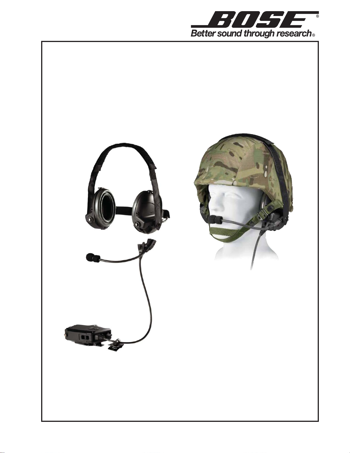
T5 Tactical Headset
©2016 Bose Corporation
Service Manual
Reference Number 350006-SM Rev. 00
Page 2

CONTENTS
Electrostatic Discharge Sensitive (ESDS) Device Handling .........................................................3
Part List Notes...................................................................................................................................3
Specifications....................................................................................................................................4
Product Description.................................................................................................................... 5-10
Single Comm Module Controls........................................................................................................6
Dual Comm Module Controls...........................................................................................................6
Manufactured Versions ..................................................................................................................11
Packaging Part Lists, T5 Headset, All Versions ...........................................................................11
User Replaceable Parts List...........................................................................................................11
System Configurations............................................................................................................. 12-13
Cables and Replacement Parts......................................................................................................14
Disassembly Procedures ......................................................................................................... 15-19
Test Procedures ........................................................................................................................ 20-26
Definitions........................................................................................................................................20
Troubleshooting........................................................................................................................ 27-29
Service Manual Revision History...................................................................................................30
IMPORTANT NOTE: These products are RoHS compliant. Use ONLY lead free solder when
making repairs.
®
CAUTION: The Bose
warranty infractions, refer servicing to warranty service stations or factory service.
THIS DOCUMENT CONTAINS PROPRIETARY INFORMATION OF
FOR THE PURPOSE OF SERVICING THE IDENTIFIED BOSE
PRODUCT BY AN AUTHORIZED SERVICE CENTER AND SHALL
NOT BE REPRODUCED OR USED FOR ANY OTHER PURPOSE.
T5 Tactical Headset contains no user serviceable parts. To prevent
PROPRIETARY INFORMATION
BOSE CORPORATION WHICH IS BEING FURNISHED ONLY
2
Page 3

ELECTROSTATIC DISCHARGE SENSITIVE (ESDS)
DEVICE HANDLING
This unit contains ESDS devices. We recommend the following precautions when repairing,
replacing or transporting ESDS devices:
• Perform work at an electrically grounded work station.
• Wear wrist straps that connect to the station or heel straps that connect to conductive floor
mats.
• Avoid touching the leads or contacts of ESDS devices or PC boards even if properly grounded.
Handle boards by the edges only.
• Transport or store ESDS devices in ESD protective bags, bins, or totes. Do not insert unprotected devices into materials such as plastic, polystyrene foam, clear plastic bags, bubble wrap
or plastic trays.
PART LIST NOTES
1. The individual parts located on the PCB are listed in the part list.
2. This part is referenced for informational purposes only. It is not stocked as a repair part.
Refer to the next higher or lower level assembly for a replacement part.
3. This part is critical for safety purposes. Failure to use a substitute replacement with the
same safety characteristics as the recommended replacement part might create shock, fire and/
or other hazards.
3
Page 4

SPECIFICATIONS
Bose® T5 TECHNICAL INFORMATION OVERVIEW
Mono and stereo available Single Comm and Dual Comm options
Weight (on head)
Control Module W eight
Dual Comm radio or intercom cables
Nominal Headband Clamping Force
Ear cup to Control Module Cable Length
Push-to-talk (PTT) on control module One momentary PTT switch for single comm
Live Mic Switch
ANR ON/OFF on control module 2-position (on/off) toggle type switch, powers headset in
Talk-through (TTC switch
Batter y Po w er
Current Draw
Operating noise environment Full ANR performance up to 123 dBSPL.
Earphone sensitivity 104 ± 3dB SPL (active) for a 0±0.1 dBV input
Input Impedance
Attenuation Performance will vary depending on the vehicle noise
Boom microphone Electret or Dynamic
Temperature Rating -40
EMI MIL-STD-461F
455g
300g
120g (max/each)
2.1 +/- 0.1 lbs.
420 +/- 50 mm
Two momentary PTT switches for dual comm
2-position (on/off) toggle type switch, used to transmit
continuously within the intercom
dismounted operations
User-selectable, 4 position rotary, Binaural
Position one: off
Position two: 0db gain
Positio n three: medium gain
Position four: high gain
2 AA batteries
ANR Only: 40 hours minimum
TT Only: 100 hours minimum
ANR and TT: 30 hours minimum
16 mA RMS nominal at 24v
Reduced ANR from 124dBSL u p to 130 dBSPL Max
94 ± 4dB SPL (bypass)
1000±10% per channel (binaural)
500±10% (monaural)
profile and crew position.
o
C to +65oC Operating
o
C to +71oC Storage
-57
4
Page 5
PRODUCT DESCRIPTION
OVERVIEW
The Bose® T5 Tactical Headset (T5TH) offers an unsurpassed combination of full-spectrum
noise reduction, comfort and clear audio in an ergonomic and rugged form factor that is compatible with a variety of helmets, intercoms and radio systems. The optional dual-communications
designed control module provides additional mission flexibility, which allows soldiers to easily
adapt the headset to fit specific mission needs.
The T5 Tactical Headset is designed to be used by infantry and other military personnel who are
primarily operating in and around tactical wheeled vehicles. These users engage in missioncritical communications and require effective noise reduction. Interpersonal communication and
situational awareness are paramount, so they value products that are operationally flexible for
mounted and dismounted use cases without sacrificing hearing protection.
KEY BENEFITS
• Clear, two-way communication provides increased situational awareness via intercom, radio
and Talk-Through feature.
• Reduction of both continuous and impulse noise provides hearing protection and allows for
increased focus on mission-critical tasks and information.
• Certain configurations can support simultaneous communications with two different devices.
• Improved ergonomic design supports both mounted and dismounted operations, and the
seamless transition between the two.
• Designed to fit securely and comfortably under combat helmets to support longer mission
profiles.
• Designed for rugged combat use while being intuitive and easy to use with limited training.
• Easily field-repairable and upgradeable.
5
Page 6
PRODUCT DESCRIPTION
Single Comm Module Controls
Dual Comm Module Controls
6
Page 7

PRODUCT DESCRIPTION
The T5 headset is capable of working in noise environments with sound pressure levels up to
115dB(C) SPL which means it is most useful in small and large wheeled vehicles as well as
many fixed and rotary wing aircraft.
The T5 headset consists of four main assemblies:
1. An active noise canceling headphone (two ear cups with ear cushions)
2. A suspension system (Napeband with over-the-head Velcro straps to support the weight)
3. A control cable assembly which provides power management, houses the necessary user
interface controls and adapts the headphone to the customer’s needs (by changing cables
to be compatible with desired source). The control cable assembly can be removed from the
earcups and replaced in the field.
4. A noise canceling boom microphone enabling communications. The microphone can be
easily replaced in the field.
The earcups each contain external-facing microphones and circuitry to allow Talk-Through, or
the ability to monitor external sounds such as speech without having to lift the earcups off of the
ear. This talk-through (TT) circuit limits external sounds to be no greater than 85dB at the ear.
The T5 headset has a volume control for the talk-through feature with volume settings will be
OFF; unamplified, medium amplification and high amplification. In all settings, the above mentioned 85dB limit is enabled.
The ear cushions used on the headset contribute to the performance as well as the overall
comfort of the headset. The ear cushions consist of polyurethane foam inside a polyurethane
film.
The napeband consists of a single, arc shaped spring formed to tuck behind the nape of the
user’s neck and head and to provide the desired clamping force. Two yokes connect the spring
to the earcups. The assembly is adjustable to fit most head sizes. The yokes and earcup
interface allow for rotation in 2 axes in order to allow optimum fit for performance as well as for
comfort. Additionally, the assembly includes a soft pad to provide cable routing and a comfortable fit behind the head for extended wear periods. The napeband / yoke assembly can be
completely disconnected from the earcups for replacement.
The control cable mates to the bottom of the left ear cup via a connector and housing that is
screwed to the earcup for robustness. This housing also mounts the flexible gooseneck boom
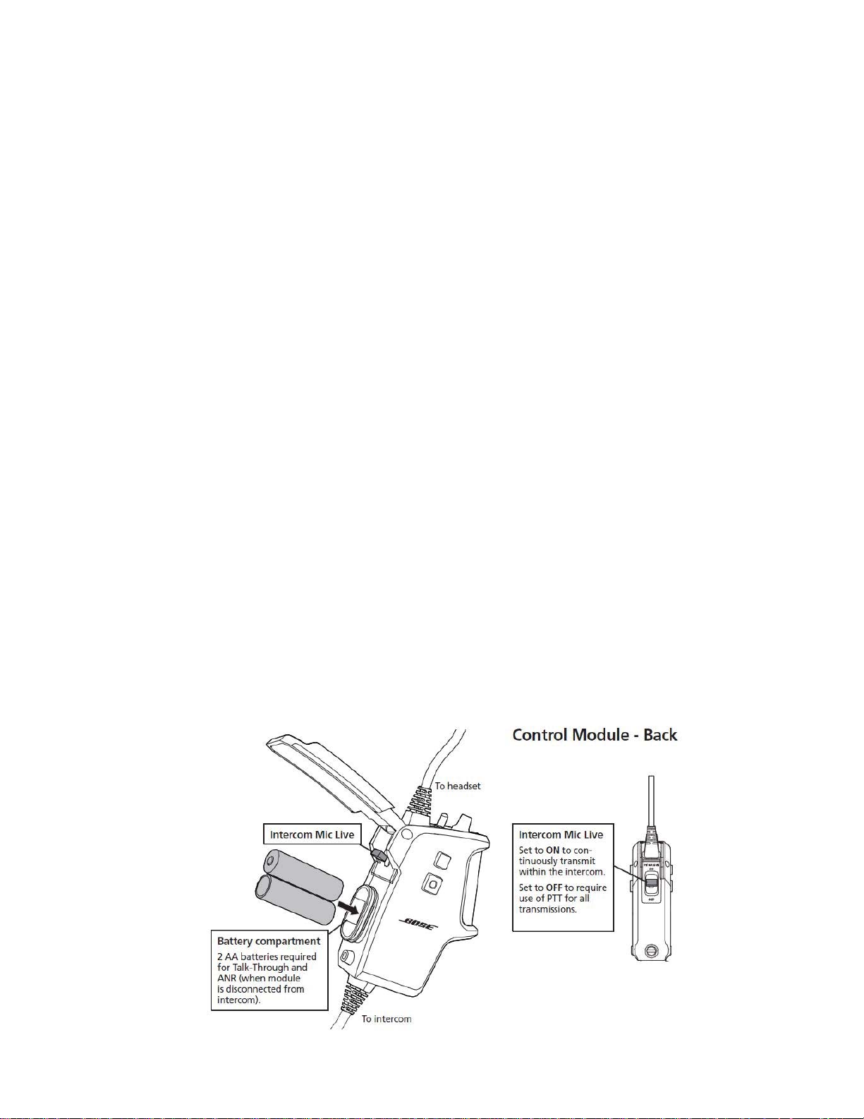
with integral noise canceling boom microphone. The control module contains a smart power
management system which can power the headset off of an external (vehicle) power source or
can use the on-board 2 AA batteries. In either case, the headset is fully functional to provide
active noise reduction (ANR), clear two way communications and talk-through capability. The
headset is also configured to provide passive noise reduction and clear two way communications when there is no power source (fail safe mode). The control module is configurable via
cable selection to enable connection of up to two input sources at any one time including intercoms, portable communication radios or other auxiliary audio or communication devices.
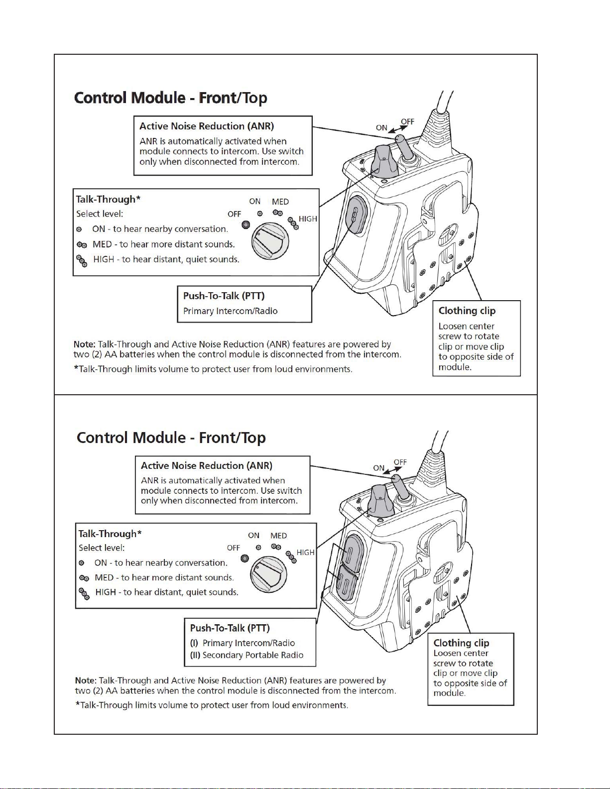
The control module also includes an integrated clothing clip that enables the module to be
securely mounted to a variety of clothing or equipment in a variety of orientations that best suit
the application at hand. The clothing clip can be mounted on both the front and the back face of
the control module in order to facilitate operation with either the left or the right hand or to cater
to different user preferences.
7
Page 8

PRODUCT DESCRIPTION
The control module switches and buttons are designed to be easily operated while wearing
typical work gloves with a material thickness of up to 3mm. They are also designed to provide
tactile feedback during operation and configured such that the mode of the switch can be
recognized visually or by feel.
The switches and their functions include:
1. Push to Talk (PTT) switch(es) (Momentary-Off)
2. 4-position rotary switch Talk Through (TT) control. The Talk Through circuit can be
powered by either the intercom (if applicable) or the 2-AA batteries in the control module.
3. Battery powered Active Noise Reduction (ANR) Switch (On-Off)
4. ICS Mic live Switch (Live-Mic, Mic-Off) This switch is used to enable continuous active
(latched) PTT mode for Intercom communications.
The boom microphone is serviceable and replaceable in the field. It is a dynamic microphone
which consists of a flexible gooseneck boom and a noise cancelling dynamic microphone
capsule. The Boom Microphone output is specific to the device it is attached to and is achievable by selecting the appropriate cable. Some options may include a pass-through while others
may include a +24dB gain to simulate an electret microphone’s output level. If gain is needed,
the power is provided by the input device OR from the control module depending on the specific
input cable. Some options may include a pass-through dynamic 150 ohm, single ended or
differential microphone.
Operation Modes (Power Compatibility)
The power modes listed below are determined by the combination of cables plugged into the
device as well as voltages that are present in different locations or vehicles. Any combination of
power modes based on input connections or signals can be configured within the electronics of
the control module including but not limited to the following scheme.
External Power Source
• Unpowered (0 – 6.0 VDC )
• Battery powered ANR (2-AA batteries)
• Gain switchable Talk Through only
• Selectable Output Level and Frequency Response (Both parameters follow the state
of ANR and/or Talk-Through)
• Boom Microphone Output is specific to device it the is attached to and is configured
inside the input cable. Some options may include a pass through while others may
include a +24dB gain to simulate an electret microphone’s output level. If gain is
needed, the power is provided by the input device OR from the control module
depending on the specific input cable.
Low Power (6.1 - 13.5 VDC)
• Battery powered ANR
- ANR Switch position has no effect
• Gain switchable Talk Through
8
Page 9

PRODUCT DESCRIPTION
Operation Modes (Power Compatibility) (continued)
Intercom Power (13.6 – 32.0 VDC)
• Battery powered ANR
- ANR Switch does not operate
• Selectable Gain switchable Talk Through
• Boom Microphone Output is specific to device it is attached to and is configured inside the
input cable. Some options may include a pass through while others may include a +24dB
gain to simulate an electrets level. If gain is needed, the power is provided by the input
device OR from the control module depending on the specific input cable.
Battery Power (2x 1.5V AA ;1.8 – 3.2 VDC)
• ANR Switch OFF and Talk Through Switch OFF
- ANR off
- Talk Through off
- Unpowered Output Level and Frequency Response
- Boom microphone output depends on cable and device it is attached to.
• ANR Switch ON and Talk Through Switch OFF
- ANR on
- Talk Through off
- Powered Output Level and Frequency Response
- Boom microphone output depends on cable and device it is attached to.
• ANR Switch ON and Talk Through Switch in any ON position
- ANR on
- Talk Through on
- Powered Output Level and Frequency Response
- Boom microphone output depends on cable and device it is attached to.
• ANR Switch OFF and Talk Through Switch in any ON position
- ANR off
- Talk Through on
- Powered Output Level and Frequency Response
- Boom microphone output depends on cable and device it is attached to.
Operation Modes (Audio Management) Dual Comm Versions:
The headset is designed to support multiple audio sources through ports located at the bottom
of the in-line control module. The behavior of each port has been designed to support a wide
range of applications. Any combination and presentation of input and output audio signals can
be configured within the electronics of the control module, including but not limited to the following scheme.
Port 1 is intended to be the primary communications port and can support binaural or monaural sources. When the source is monaural, the cable for that device is wired such that the
monaural signal is paralleled so that it is made compatible with the binaural connection and the
user will always hear the audio from Port 1 in both ears. Whenever Port 1 is connected, pressing PTT 1 shorts the control line to the Port 1 source which enables transmission of the boom
microphone signal to the Port 1 source. If there is no source connected to Port 1, nothing
happens when PTT 1 is pressed.
9
Page 10

PRODUCT DESCRIPTION
Operation Modes (Audio Management) Dual Comm Versions (continued):
Port 2 is intended to be a secondary communications port. The presentation of this source’s
audio to the headset depends upon the presence of a cable plugged into Port 1.
If Port 1 has a cable plugged in, the audio from the Port 2 device will only be presented to the
left earcup. In order to properly mix the audio between the multiple sources while maintaining
the dynamic range of the headset, the two signals will each be reduced by 6dB. The reduction
will occur as soon as the second cable is attached to the port on the bottom of the control
module .
If Port 1 does not have a cable plugged in, the audio from the Port 2 device will be presented to
both earcups and will not be reduced by 6dB.
Binaural devices may be connected to Port 2, however the cable connecting this type of source
to the control module will mix the two separate channels onto one signal line and present the
device as a mono device to the headset. Whenever Port 2 has a cable connected to it, pressing
PTT 2 shorts the control line to ground of the Port 2 source which enables transmission of the
boom microphone signal to the Port 2 source. If there is no cable connected to Port 2, nothing
happens when PTT 2 is pressed. The “Mic live” switch has no effect on any Port 2 device under
any configuration.
The table below describes how the headset manages the multiple audio sources based on what
cables are connected as well as how the PTT buttons function. An N/A in a cell means there is
no cable connected or there is no function. There are many variations of this that are possible.
Mode of operation Port 1 Port 2 Left Earcup Right Earcup
Unpowered X N/A Port 1 Port 1
Unpowered N/A X Port 2 Port 2
Unpowered X X Port 1 + Port 2 Port 1 + Port 2
Battery Powered X N/A Port 1 Port 1
Battery Powered N/A X Port 2 Port 2
Battery Powered X X Port 1 Port 2
ICS powered 6-32 V X N/A Port 1 Port 1
ICS powered 6-32 V X X Port 1 + Port 2 Port 1
10
Page 11

MANUFACTURED VERSIONS
V
ersion Description Material Master / SKU Number
HDST/MOD ASSY, SINGLE COMM, MONAURAL 349999-1100
HDST/MOD ASSY, SINGLE COMM, BINAURAL 349999-1200
HDST/MOD ASSY, T5, DUAL COMM 349999-2000
HDST ASSY, T5, DUAL, W/M-ICOMM/R-SEC CBLS 374120-2000
PACKAGING PART LISTS
T5 Headset, All Versions
Item
Description Part Number Qty.
Number
1 HDS T /M OD AS SY, SIN G LE C O MM , MO NA U RA L
HDST/MOD ASSY, SINGLE COMM, BINAURAL
HDST/MOD ASSY, T5, DUAL COMM
350006-1100
350006-1200
350006-2000
1
2 CARTON , RSC, 9. 00X7 .00X 5. 25, C 27 7035-01 1
3 CARTON, RSC, 19.00X15.00X12.13, C 277036-01 1
4 BAG, POLY, 16x 14 178245- 1 1
5 PKG, 3/1 6 HIGH BUBBLE COHESIVE 1 96054 2
6 BAG, POLY, 3x7 x.1 8 BUBBLE 1 49277 2
7 B AT TE R Y, AA SIZE, PAIR 263269-002 1
8 GUIDE, T5, SINGLE COMM
GUIDE, T5, DUAL COMM
355885-0010
354584-0010
1
USER REPLACEABLE PARTS LIST
Item
Number
1 CABLE, DUAL, ICOMM, T5, AMP/CONN, NF, MONO 354702-1110
2 CABLE, DUAL, RADIO, T5, NF, PRI MARY 354704-1130
3 CABLE, DUAL, ICOMM, T5, AMP/CONN, NF,
BINAURAL
4 CABLE, DUAL, RADIO, T5, NF, SECONDARY 354704-2130
5 MODULE ASSY, T5, DUAL COMM, SPARE 356190-2000
6 MODULE ASSY, T5, SINGLE COM, MONAURAL,
SPARE
7 MODULE ASSY, T5, SINGLE COM, BINAURAL,
SPARE
8 BOOM MIC ASSY, SPARE 356195-0010
9 WINDSCREEN, BOOM MIC, SPARE 280191-001 5965-01-525-1684
10 NAPEBAND/YOKE ASSY, W /COVER, SPARE 356199-0010
11 NAPEBAND, COVER, SPARE 280187-001 5965-01-525-2019
12 HEADSTRAP KIT, SPARE 277285-001 5965-01-525-1695
13 EAR CUSHION PAIR, SPARE 356202-0010
14 EARCUPS ASSY, T5, SPARE
(WITHOUT NAPE BAND / YOKE ASSEMBLY)
15 CLOTHING CLIP, SPARE 310490-0010
16 BATTERY DOOR, MODULE, SPARE 356205-0010
17 CASE, HEADSET, T5 361424-0010
18 HEADPHONE ASSY,T5,W/NAPEBAND,SPARE 370075-0010
19 MOD ASSY, W/O BOOM MIC, T5, SINGLE,
MONAURAL
20 MOD ASSY, W/O BOOM MIC, T5, SINGLE,
BINAURAL
21 MOD ASSY, W/0 BOOM MIC, T5, DUAL, COMM 370250-2000
22 HEADPHONE ASSY W/NAPEBAND, T5 370075-0010
Description Part Number NSN Number
354702-1220
356190-1100
356190-1200
356203-0010
370250-1100
370250-1200
11
Page 12

System Configurations
12
Page 13

System Configurations (continued)
13
Page 14

Cables and Replacement Parts
280191-001
277285-001
14
Page 15

DISASSEMBLY PROCEDURES
IMPORTANT NOTE: These products are
RoHS compliant. Use ONLY lead free
solder when making repairs.
1. Boom Microphone Replacement
1.1 Loosen the captive screw that retains
the boom microphone base to the left
earcup.
1.2 Gently pull the base of the boom microphone away from the earcup. Unplug the
boom microphone connector from the wiring
harness.
Note:
Reverse this procedure for installing a
replacement boom microphone.
2. Ear Cushion Replacement
2.1 Insert your fingers at the location
indicated in the photo at left and pull off the
ear cushion from the earcup.
2.2 Remove any residual glue from the
earcup assembly.
2.3 Remove and discard the tape liners
from the replacement ear cushion.
15
Page 16

DISASSEMBLY PROCEDURES
2.4 Align and press the replacement ear
cushion onto the earcup assembly until it
snaps into place. Ensure it is fully seated.
3. Nape Band Replacement
Yoke pin
Cable on outer side
3.1 Remove nape band cover
3.2 Press upward on nape band yoke until
the yoke pin clears the earcup. Disengage
the lower yoke pin from the earcup. Perform
this step on the other earcup.
3.3 Insert the replacement nape band upper
yoke pin into the earcup upper pin hole.
Press downward on the yoke and engage
the lower yoke pin in the earcup lower pin
hole.
3.4 Replace the nape band cover. Only the
middle portion secures the earcup wire to
the nape band.
Note: The cable running between the
earcups should be on the outer side of the
yoke. Remove and reuse serial number
label on replacement nape band. Attach
new product label to nape band.
4. Earcup Assembly Replacement
Note: The earcup assembly includes both
earcups, the nape band w/cover and the
head strap.
4.1 Remove the two captive screws that
secure the control module cable / boom
microphone to the bottom of the left earcup.
4.2 Gently pull the control module cable /
16
Page 17

DISASSEMBLY PROCEDURES
boom microphone assembly straight down
and away from the earcup. It should unplug
from the left earcup connector as a unit.
5. Control Module Replacement
Note: The control module is not repairable.
It is a sealed unit. The control module
cables are not replaceable separately
from the control module.
5.1 Loosen the captive screw that secures
the boom microphone assembly to the left
earcup. Gently pull the boom mic assembly
away from the earcup.
Unplug the boom microphone from the
earcup wiring harness.
5.2 Loosen the two captive screws that
secure the control module cable to the
bottom of the left earcup. Gently pull the
17
Page 18

DISASSEMBLY PROCEDURES
control module cable straight down. It
should unplug from the bottom of the left
earcup.
6. Battery Cover Replacement
6.1 On the control module, loosen the
captive screw that holds the battery door
closed over the batteries. Do not completely
remove the screw.
6.2 On the control module, remove the
screw and nut that secure the battery cover.
Take care to not lose the small nut. It is not
captive to the control module.
Reassembly Note: The small nut should be
re-installed on the same side as the clothing
clip, as shown in the photo at left.
7. Head Strap Assembly Replacement
7.1 Using a T10 Torx head wrench, remove
the screw securing the head strap to the
earcup assembly. Repeat this for the other
earcup.
7.2 Reattach the replacement head strap
using the screw removed in step 7.1.
18
Note: The replacement head strap comes
as a set. Ensure the strap loops are facing
Page 19

DISASSEMBLY PROCEDURES
outward on each earcup. When worn, the
straps should interlock without twisting.
8. Attachment Clip Replacement /
Relocation
8.1 Remove the screw securing the attach-
ment clip to the control module.
8.2 Align the square alignment holes on the
replacement clip to the alignment feature on
the control module and secure with the
screw removed in step 8.1.
Note: The clip can be installed on either
side of the control module and either
perpendicular or parallel to the cable.
19
Page 20

TEST PROCEDURES
Note: The following procedures contain two
separate test procedures.
The first test is for internal Bose
centers that have the required Bose final
audio test system.
The second test procedure is a less complex
light-up-and-play type test for repairs performed in the field.
Internal Bose Repair Center Tests
Equipment Required
The following hardware and software are
needed to perform the tests described
herein. Equivalent hardware may be substituted.
IMPORTANT NOTE: These products are
RoHS compliant. Use ONLY lead free
solder when making repairs.
®
repair
Test Setup
• Install two AA batteries into the control
module for talk through capability.
• Connect the headset to the
intercommunications system
Definitions
Background Noises Noise present in the
absence of other excitation, including the
following:
• Hum Constant low frequency signal,
caused by power line interference.
• Hiss Steady, broad mid-to-high frequency
signal caused by noise of headset electronics.
• Static Intermittent crackling signal, caused
by external electrical interference.
• Whine Sharp continuous signal, caused by
narrow overvoltage pulses on power line.
• Ripple Noises caused by interference on
power supply line at various frequencies.
Bose Final Audio Test System
This system connects to the headset and
provides all stimulus signals necessary to
excite the headset for listening tests.
The room in which tests are performed must
be within the following range of environmental conditions:
• Temperature - between 62°F and 82°F
• Humidity - between 10% and 90% R.H.
• Ambient Noise - less than 45 dB(C)SPL
• Noise Signal for noise attenuation listening.
- The test system must produce broad
band noise, 50 Hz to 10 kHz, approximately pink (third-octave spectrum flat
vs. frequency) below 1 kHz and thirdoctave spectrum weighted approximately
inversely with frequency above 1 kHz,
overall level 94 dB SPL ±3 dB. Duration
of 30 minutes or more and must not
repeat more than one time during that
interval.
Instability Noises related to acoustic leaks
or malfunctions compromising stability,
including the following:
• Squeal Mid-to-high frequency variable
tone.
• Motor-boating Lower frequency periodic
noise.
• Buzz Harmonic produced by vibration in
the presence of an audio signal. This noise
is usually related to mechanical faults.
Overload Noises related to movement,
pressure or impact on headset as well as
extremely high external noise, including the
following:
• Click Sharp transient caused by collapse
of driver diaphragm. Generally very noticeable.
• Thump Low frequency transient, caused
by saturation of headset electronics.
• Pop Low frequency transient, caused by
saturation of ANR loop.
20
Page 21

TEST PROCEDURES
1. Active Noise Reduction (ANR) Operation,
Quiet Environment
Setup Conditions:
• Talk Through (TT) swith - OFF
• Power supply input - 3.0 Volts
(2 AA batteries) in control module
• Headset microphone switch - OFF
• Headset battery ANR switch - OFF
1.1 In a quiet environment, listen to the ANR
operation as you stand still. Ensure that the
earcups are properly seated on your head.
1.2 Slowly compress the cups against your
head with your hands. Move the earcups with
your hands to simulate rapid head and jaw
movement.
1.3 Lift one of the earcups off of the ear
slightly at the back of the jaw to create a
small air leak. Listen for overload or instability conditions. Perform this step for the other
earcup.
P ASS/FAIL Criteria. Overload or instability
should not be heard under any test conditions. When creating a leak in the back of the
jaw, short term (less than 1 second) instability is allowed. If the instability is sustainable
by holding the earcup in the position where
the instability was heard, the headset has
failed this test.
2. Active Noise Reduction (ANR) Operation,
Loud Environment
Setup Conditions:
• Talk Through (TT) swith - Off
• Power supply input - 3.0 Volts
(2 AA batteries) in control module
• Headset microphone switch - Off
• Headset battery ANR switch - Off
• Sound Booth Noise Switch - On
• Sound Booth Audio Switch - Off
2.1 Listen to ANR operation as you stand
still. Ensure that the earcups are sealed to
your head.
2.2 Slowly compress the cups against the
head with your hands. Move the earcups
with your hands to simulate rapid head and
jaw movement. Listen for overload or
instability conditions.
P ASS/FAIL Criteria. ANR Operation should
be apparent. Overload or instability should
not be heard under any test conditions.
3. Talk -Through (TT) Operation, ANR OFF
This test is to verify talk-through balance
and intelligibility.
Setup Conditions:
• TT switch - Talk-through ON 0dB
• Power supply input - 3.0 Volts
(2 AA Batteries) in Control Module
• Headset Microphone switch - Off
• Headset Battery ANR Switch - Off
• Sound Booth Noise Switch - Off
• Sound Booth Audio Switch - On
3.1 Talk-through Balance - Listen to the
audio signal while facing the signal source.
3.2 Block the left talk through microphone
with your hand and listen to the audio
signal through the right.
3.3 Uncover the left side and cover the
right side. Listen to the audio signal through
the left side.
PASS/FAIL Criteria. The audio signal
should be heard at the same level in both
sides of the headset and there should be
no noticeable background noise.
3.4 Talk-through Intelligibility. Listen to a
minimum of four words from the audio
signal.
PASS/FAIL Criteria. Words should be
heard clearly, and should be recognizable.
3.5 Talk-through Gain Switching. Move the
TT rotary switch to the 5dB position.
21
Page 22

TEST PROCEDURES
PASS/FAIL Criteria. Words should be heard
clearly and be recognizable.
3.6 Talk-through Compressor Operation.
Listen to the audio signal. Move the gain
switch to the +15dB position. Wait for the
sound of words to stablilize before listening
to a minimum of four words from the audio
signal.
PASS/FAIL Criteria. The level of sound
heard through the talk-through must not
increase dramatically after the sound of
the words stabilizes. If verification is
needed compare ambient sound at
increased gain level to sound heard
through the talk-through system.
If headset’s compressor takes longer than
five words to stabilize, it is a failure.
4. Talk-through Operation, Active Noise
Reduction (ANR) ON, Quiet Environment
This test verifies proper Talk-through
balance, intelligibility and compressor operation.
Set-Up Conditions:
• TT switch - Talk-through ON - 0dB
• Power supply input - 3.0 Volts
(2 AA Batteries) in Control Module
• Headset Microphone switch - Off
• Headset Battery ANR Switch - Off
• Sound Booth Noise Switch - Off
• Sound Booth Audio Switch - On
5. Talk-Through Operation, ANR ON
This test is to verify Talk- through balance,
and intelligibility .
Set-Up Conditions:
• TT switch - Talk-through ON 0dB
• Power supply input - 3.0 Volts
(2 AA Batteries) in Control Module
• Headset Microphone switch - Off
• Headset Battery ANR Switch - On
• Sound Booth Noise Switch - Off
• Sound Booth Audio Switch - Off
5.1 Talk-through Balance. Listen to the
audio signal while facing the signal source.
Block the left talk through microphone with
your hand and listen to the audio signal
through the right.
5.2 Uncover the left side and cover the
right side. Listen to the audio signal through
the left side.
PASS/FAIL Criteria. The audio signal
should be heard at the same level in both
sides of the headset and there should be
no noticeable background noise.
5.3 Talk-through Intelligibility. Listen to a
minimum of four words from the audio
signal.
PASS/FAIL Criteria. Words should be
heard clearly, and should be recognizable.
4.1 Talk-through Gain. Listen to the
Talk-through background noise in a quiet
environment. Exercise the TT Switch to
+5dB and +10dB positions respectively.
PASS/FAIL Criteria. The noise of the TT
circuit should increase for both earcups at
the +5dB position, and then increase for
both earcups again at the +10dB position.
The headset should not oscillate with either
+5 or +10dB gain.
5.4 Talk-through Gain Switching. Exercise
the TT Rotary switch to the 5dB position.
PASS/FAIL Criteria. Words should be
heard clearly, and should be recognizable.
5.5 Talk-through Compressor Operation.
Listen to the audio signal. Switch the gain
switch to +15 dB. Wait for the sound of
the words to stabilize before listening to a
minimum of four words from the audio
signal.
22
Page 23

TEST PROCEDURES
PASS/FAIL Criteria. The level of sound
heard through the talk-through must not
in-crease dramatically after the sound of
the words stabilizes. If verification is needed
compare ambient sound at increased gain
level to sound heard through the talkthrough system. If headset’s compressor
takes longer than 5 words to stabilize, it is a
failure.
6. Talk-Through Operation, ANR OFF,
Quiet Environment
This test is used to verify Talk-through
balance, intelligibility, and compressor
operation.
Set-Up Conditions.
• TT switch - Talk-through ON - 0dB
• Power supply input...3.0 Volts
(2 AA Batteries) in Control Module
• Headset Microphone switch - Off
• Headset Battery ANR Switch - Off
• Sound Booth Noise Switch - Off
• Sound Booth Audio Switch - On
6.1 Talk-through (TT) Gain. Listen to the
Talkthrough background noise in a quiet
environment. Exercise the TT Switch to
+5dB and +10dB positions respectively.
PASS/FAIL Criteria. The noise of the TT
circuit should increase for both earcups at
the +5dB position, and then increase for
both earcups again at the +10dB position.
The headset should not oscillate with either
+5 or +10dB gain.
Field Repair Light-up-and-Play Tests
1.2 Play an audio signal to the headset.
Verify that you can hear the audio being fed
to the headset from the radio or intercomm.
1.3 Speak into the microphone. Verify that
your voice signal is being received by the
radio / intercomm.
1.4 Disconnect the headset from the radio
or intercomm and perform the battery
powered tests located after the below noise
definitions.
Definitions
Background Noises Noise present in the
absence of other excitation, including the
following:
• Hum Constant low frequency signal,
caused by power line interference.
• Hiss Steady, broad mid-to-high frequency
signal caused by noise of headset electronics.
• Static Intermittent crackling signal, caused
by external electrical interference.
• Whine Sharp continuous signal, caused by
narrow overvoltage pulses on power line.
• Ripple Noises caused by interference on
power supply line at various frequencies.
Instability Noises related to acoustic leaks
or malfunctions compromising stability,
including the following:
• Squeal Mid-to-high frequency variable
tone.
• Motor-boating Lower frequency periodic
noise.
• Buzz Harmonic produced by vibration in
the presence of an audio signal. This noise
is usually related to mechanical faults.
1. Intercomm/Radio Communications Test
After repair, connect the headset to a
compatible radio or intercomm system and
verify that all functions work properly. Once
the headset has passed test, it can be
returned to use.
1.1 Connect the headset control module
cable to the radio or intercomm.
Overload Noises related to movement,
pressure or impact on headset as well as
extremely high external noise, including the
following:
• Click Sharp transient caused by collapse
of driver diaphragm. Generally very noticeable.
• Thump Low frequency transient, caused
by saturation of headset electronics.
• Pop Low frequency transient, caused by
saturation of ANR loop.
23
Page 24

TEST PROCEDURES
2. Active Noise Reduction (ANR) Operation, Quiet Environment
Setup Conditions:
• Talk Through (TT) swith - OFF
• Power supply input - 3.0 Volts
(2 AA batteries) in control module
• Headset microphone switch - OFF
• Headset battery ANR switch - OFF
2.1 In a quiet environment, listen to the ANR
operation as you stand still. Ensure that the
earcups are properly seated on your head.
2.2 Slowly compress the cups against your
head with your hands. Move the earcups
with your hands to simulate rapid head and
jaw movement.
2.3 Lift one of the earcups off of the ear
slightly at the back of the jaw to create a
small air leak. Listen for overload or instability conditions. Perform this step for the other
earcup.
3.2 Slowly compress the cups against the
head with your hands. Move the earcups
with your hands to simulate rapid head and
jaw movement. Listen for overload or instability conditions.
P ASS/FAIL Criteria. ANR Operation should
be apparent. Overload or instability should
not be heard under any test conditions.
4. Talk -Through (TT) Operation, ANR OFF
This test is to verify talk-through balance
and intelligibility .
Setup Conditions:
• TT switch - Talk-through ON 0dB
• Power supply input - 3.0 Volts
(2 AA Batteries) in Control Module
• Headset Microphone switch - Off
• Headset Battery ANR Switch - Off
4.1 Talk-through Balance - Listen to an
audio source such as spoken word.
P ASS/FAIL Criteria. Overload or instability
should not be heard under any test conditions. When creating a leak in the back of
the jaw, short term (less than 1 second)
instability is allowed. If the instability is
sustainable by holding the earcup in the
position where the instability was heard, the
headset has failed this test.
3. Active Noise Reduction (ANR) Operation, Loud Environment
Setup Conditions:
• Talk Through (TT) swith - Off
• Power supply input - 3.0 Volts
(2 AA batteries) in control module
• Headset microphone switch - Off
• Headset battery ANR switch - Off
3.1 Listen to ANR operation as you stand
still. Ensure that the earcups are sealed to
your head.
4.2 Block the left talk through microphone
on the earcup with your hand and listen to
the audio signal through the right.
4.3 Uncover the left side and cover the
right side microphone. Listen to the audio
signal through the left side.
PASS/FAIL Criteria. The audio signal
should be heard at the same level in both
sides of the headset and there should be
no noticeable background noise.
4.4 Talk-through Intelligibility. Listen to a
minimum of four words from the audio
source.
PASS/FAIL Criteria. Words should be
heard clearly, and should be recognizable.
4.5 Talk-through Gain Switching. Move the
TT rotary switch to the 5dB position.
24
PASS/FAIL Criteria. Words should be
heard clearly and be recognizable.
Page 25

TEST PROCEDURES
4.6 Talk-through Compressor Operation.
Listen to the audio source. Move the gain
switch to the +15dB position. Wait for the
sound of words to stablilize before listening
to a minimum of four words from the audio
signal.
PASS/FAIL Criteria. The level of sound
heard through the talk-through must not
increase dramatically after the sound of
the words stabilizes. If verification is
needed compare ambient sound at
increased gain level to sound heard
through the talk-through system.
If headset’s compressor takes longer than
five words to stabilize, it is a failure.
5. Talk-through Operation, Active Noise
Reduction (ANR) ON, Quiet Environment
This test verifies proper Talk-through
balance, intelligibility and compressor
operation.
Set-Up Conditions:
• TT switch - Talk-through ON - 0dB
• Power supply input - 3.0 Volts
(2 AA Batteries) in Control Module
• Headset Microphone switch - Off
• Headset Battery ANR Switch - Off
6. Talk-Through Operation, ANR ON
This test is to verify Talk- through balance,
and intelligibility .
Set-Up Conditions:
• TT switch - Talk-through ON 0dB
• Power supply input - 3.0 Volts
(2 AA Batteries) in Control Module
• Headset Microphone switch - Off
• Headset Battery ANR Switch - On
6.1 Talk-through Balance. Listen to the
audio source while facing it. Block the left
talk through microphone on the earcup with
your hand and listen to the audio signal
through the right.
6.2 Uncover the left side and cover the
right side microphone. Listen to the audio
signal through the left side.
PASS/FAIL Criteria. The audio signal
should be heard at the same level in both
sides of the headset and there should be
no noticeable background noise.
6.3 Talk-through Intelligibility. Listen to a
minimum of four words from the audio
source.
5.1 Talk-through Gain. Listen to the
Talk-through background noise in a quiet
environment. Exercise the TT Switch to
+5dB and +10dB positions respectively.
PASS/FAIL Criteria. The noise of the TT
circuit should increase for both earcups at
the +5dB position, and then increase for
both earcups again at the +10dB position.
The headset should not oscillate with either
+5 or +10dB gain.
PASS/FAIL Criteria. Words should be
heard clearly, and should be recognizable.
6.4 Talk-through Gain Switching. Exercise
the TT Rotary switch to the +5dB position.
PASS/FAIL Criteria. Words should be
heard clearly, and should be recognizable.
6.5 Talk-through Compressor Operation.
Listen to the audio signal. Switch the gain
switch to +15 dB. Wait for the sound of
the words to stabilize before listening to a
minimum of four words from the audio
signal.
25
Page 26

TEST PROCEDURES
PASS/FAIL Criteria. The level of sound
heard through the talk-through must not
in-crease dramatically after the sound of
the words stabilizes. If verification is needed
compare ambient sound at increased gain
level to sound heard through the talkthrough system. If headset’s compressor
takes longer than 5 words to stabilize, it is a
failure.
7. Talk-Through Operation, ANR OFF,
Quiet Environment
This test is used to verify Talk-through
balance, intelligibility, and compressor
operation.
Set-Up Conditions.
• TT switch - Talk-through ON - 0dB
• Power supply input...3.0 Volts
(2 AA Batteries) in Control Module
• Headset Microphone switch - Off
• Headset Battery ANR Switch - Off
7.1 Talk-through (TT) Gain. Listen to the
Talk-through background noise in a quiet
environment. Exercise the TT Switch to
+5dB and +10dB positions respectively.
PASS/FAIL Criteria. The noise of the TT
circuit should increase for both earcups at
the +5dB position, and then increase for
both earcups again at the +10dB position.
The headset should not oscillate with either
+5 or +10dB gain.
26
Page 27

V
Troubleshooting
Some field issues may be related to confusion regarding the different configurations and modes
of operation of the headset. Refer to the product description section of this manual for more
information regarding this before troubleshooting.
Note: No internal parts of the headset or control module are serviceable in the field.
The headset is field repairable at a higher level, i.e. control module, earcups, cables, etc. The
list of user replaceable parts is located on page 11 of this manual. Problems associated with the
headset (driver faults, earcup PCB faults, etc.) require the product to be returned to Bose
Corporation for repair.
The troubleshooting steps below describe problems that can be resolved in the field. Refer to
the list of Listening Test Defects in the Test Procedures section for additional information and
specific failure descriptions.
Symptom
No Audio
No Audio from one
Earcup
Intermittent Operation
and/or One or Both
Ears Intermittent.
One ear completely
inoperative: (No ANR
and no audio whether
switched on or off).
erification/Solution
Is ANR present? Are you connected to the vehicle? Power is
provided by the vehicle when connected to it. Connect known good
headset to same connection on the vehicle. Do you have audio now?
If so problem is with headset. Check all cables, earcups and control
module for damage. If still no audio replace earcup assembly. If not,
problem is with the connection or equipment in the vehicle.
Check sidetone. If you cannot hear your own voice, have someone
using another headset on the same intercom circuit speak. If you can
hear them, you may have a bad microphone. If still no audio, problem
could be in the cable, control module or earcups. Replace the cable.
Okay? If not, replace control module. Okay? If not, then replace
earcups.
Check Talk-Through (TT) switch setting – The TT circuits are
designed to deliver audio at a level up to 85 dB SPL at your ear. An
externally overloaded TT circuit will cause interrupted audio in the
earcups, preventing sound pressure levels of >85 dB SPL from
getting to the ear. This occurs if the TT gain setting is too high at the
rotary switch on the control module and you communicate too loudly,
overwhelming the signal and causing audio dropouts.
Check batteries - There is no LED on the product to allow monitoring
of the battery power level. Low battery when in ANR or TT mode will
cause intermittent operation or clicking every few seconds to indicate
weak batteries. Unit will continue to operate in this mode for some
time before the batteries fail entirely and the unit operation reverts to
fail-safe operation mode. ANR will be intermittent with clicking every
few seconds.
Check that all cables for damage and are fully seated. Replace cable
as needed.
Connect a known good control module and cable. Connect to a
known good source and retest. If still intermittent, replace earcups. If
audio is good with known good control module, replace original
control module.
Check all cables for damage.
Connect a known good control module and cable. Connect to a
known good source and retest. If still inoperative, replace earcup
assembly.
27
Page 28

V
Troubleshooting
Symptom
No Output from
Microphone
Low microphone
output, intermittent
microphone
transmissions or
difficult to break
intercom squelch.
No Active Noise
Reduction (ANR) or
Reduced ANR
Audio from only one
source on Dual
Comm versions
Unpowered (Fail
Safe) Mode Not
Work i n g Wh e n No t
Connected to Vehicle
erification/Solution
Check for damage or contamination, i.e. rust, chewing tobacco,
debris. If mic is damaged or contaminated, replace it.
Check microphone connection to the headset. Ensure wiring harness
is not damaged and that the connector pins are not bent and
connector is properly seated.
Replace microphone with a known good one. Retest. If okay, replace
original microphone.
Make sure unit is turned on.
Check power. Battery or external? ANR switch only controls battery
powered ANR, not external (vehicle) powered. ANR will be on all the
time when connected to vehicle power.
Check for defective cables, cracking of strain reliefs and/or bent pins.
Replace cable as needed.
Check position of Talk-Through (TT) rotary switch - The talk-through
function allows external audio from the microphone to be fed through
the headset without removing it, i.e. to speak to someone in the same
vehicle. Leaving TT on will reduce ANR and should only be used
when needed. Talk-through switch must be OFF for ANR to work
completely.
Check for low battery if not vehicle powered. There is no LED on the
product to allow monitoring of the battery power level. Low battery
when in ANR or TT mode will cause intermittent operation or clicking
every few seconds to indicate weak batteries. Unit will continue to
operate in this mode for some time before the batteries fail entirely
and the unit operation reverts to fail-safe operation mode. ANR will
be intermittent with clicking every few seconds.
Check all cables, earcups and control module for damage. Check for
damage or blockage of the microphone ports on the earcups. These
microphones are used to pick up noise in the environment in order to
cancel it. Damage or blockage will affect ANR functionality.
Check for defective switches on control module. If inoperative,
replace control module.
Connect a known good control module and cable. Connect to a
known good source and retest. If still bad ANR, replace earcups.
Port 1 is primary source and Port 2 is the secondary source. Ensure
you have correct cables and connections for the desired mode of
operation. Refer to the Dual Comm Mode of Operation table listed
previously in this manual.
Check all cables and control module for damage.
Connect known good cables from the control module to the radio.
Retest. If okay, re pla c e original cable.
Connect known good control module. If okay, replace control module.
Ensure control module switches are not intermittent. If bad, replace
control module.
Single Comm – Headset Not capable of operating in unpowered fail-
safe mode when in dismounted mode. Will allow for ANR and TT
when operating dismounted on battery power.
28
Page 29

Troubleshooting
V
Symptom
Mic Live Switch not
working on Port 2
(Dual Comm
versions)
Live Mic Button Not
Working
Talk-through (TT) Not
Working
(PTT) Button Not
Working Properly
Latched Mode of the
Push To Talk (PTT)
Button Not Working
Properly
Loud clicking/ticking
or thumping noise in
either or both ears.
Buzzing/humming
noises when touching
Electro-Luminescent
instrument panels.
Static heard through
headset
High frequency
squeal or oscillation
erification/Solution
By design, the Mic live switch has no effect on any Port 2 device
under any configuration.
Button is located on the back of the control module. This button is
only enabled while operating from vehicle power. It is disabled when
operating from portable radios.
Check switch function with vehicle power to see if it is intermittent. If
so, replace control module.
Check all cables, earcups and control module for damage. Check
control module for bad TT rotary switch.
Replace microphone with a known good one. Retest. If okay.
Replace original microphone.
Connect a known good control module and down cable and connect
to a known good source and retest. If still not working, replace
earcups.
Check vehicle radio. Connect a known good headset to vehicle
connector. If okay, problem is with headset. Check connectors and
cables for damage.
Connect a known good control module to the earcup assembly.
Retest on vehicle radio. If okay, replace control module. If still bad,
problem is in the earcup assembly.
Latched mode of PTT – Intercom mic/line switch - Enabled only in
presence of vehicle of vehicle supplied power. Used inside vehicle
over intercom. Allows comms over a radio that is connected to the
intercom. PTT allows audio pass-through to radio.
Inspect the driver for any debris such as hair or sand.
Remove ear cushion. Check the driver membrane for dimples or
creases. If found, replace the earcup assembly.
If noise is continuous and increases when your hand is moved closer
to the instrument panel, then the headset is probably receiving
interference from the lighting. This is particularly true if when you
touch grounded metal the noise goes away.
These noises will not harm the headset; however, they may be
annoying and distracting for the user.
Connect to a known good source. If okay, problem is with the source.
Check cables and earcups for damage. Check earcup driver
membrane for debris or damage such as dimples or creases.
Connect known good control module and cable. If good, replace
control module. If still bad, replace earcups.
Inspect the driver for any debris such as hair or sand.
Remove ear cushion. Check the driver membrane for dimples or
creases. If found, replace the earcup assembly.
Check for missing or deteriorated ear cushions.
29
Page 30

Service Manual Revision History
Date Revision
Level
3/2016 00 Document released at revision 00. Service manual
Description of Change Change Driven
By
release
Pages
Affected
All
30
Page 31

Specifications and Features Subject to Change Without Notice
Bose Corporation
The Mountain
Framingham Massachusetts USA 01701
P/N: 350006-SM REV. 00; 3/2016 (M)
http://serviceops.bose.com
 Loading...