

Page 1
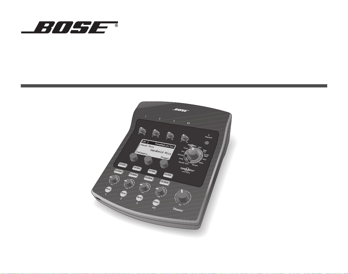
TM
T1 ToneMatch
AUDIO ENGINE
Owner’s Guide
Page 2
QUICK PATH TO MAKING MUSIC
To get sound right away
1. Remove your new T1 ToneMatchTM
audio engine from the carrying bag and
remove its protective cover (page 6).
2. Refer to the Quick Setup Guide and
connect your T1 to your L1
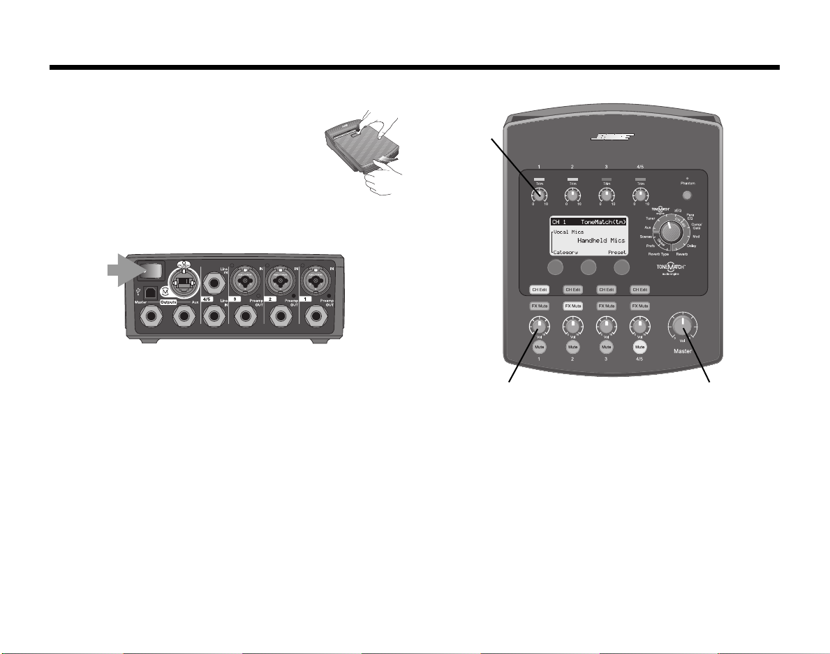
3. Make sure the T1 Master volume
control is set to 0 (page 16).
4. Turn on the T1 and then turn on your L1 model II system.
ON
5. Plug your instrument or microphone into the Channel 1
input on the back of the T1 (page 4).
6. Play your instrument or sing into the microphone. Turn the
CH 1 Trim control clockwise until the input signal indicator glows green (page 16).
7. Slowly turn the T1 Master volume control up until it is
approximately in the 12 o’clock position (page 16).
8. Slowly turn the CH 1 Vo l control up until you hear your
instrument or microphone (page 16).
TM
system.
EnglishDeutschEspañolFrançaisItalianoNederlandsSvenska Dansk
Trim
(CH 1)
Vol (CH 1)
Master
IMPORTANT!
Please make sure you read “Optimizing input gain and
output volume” on page 16. This explains how to properly adjust the input trim, channel volume, and master
volume controls for the best possible sound.
ii
Page 3
SvenskaItalianoFrançaisEspañolDeutschDanskEnglish Nederlands
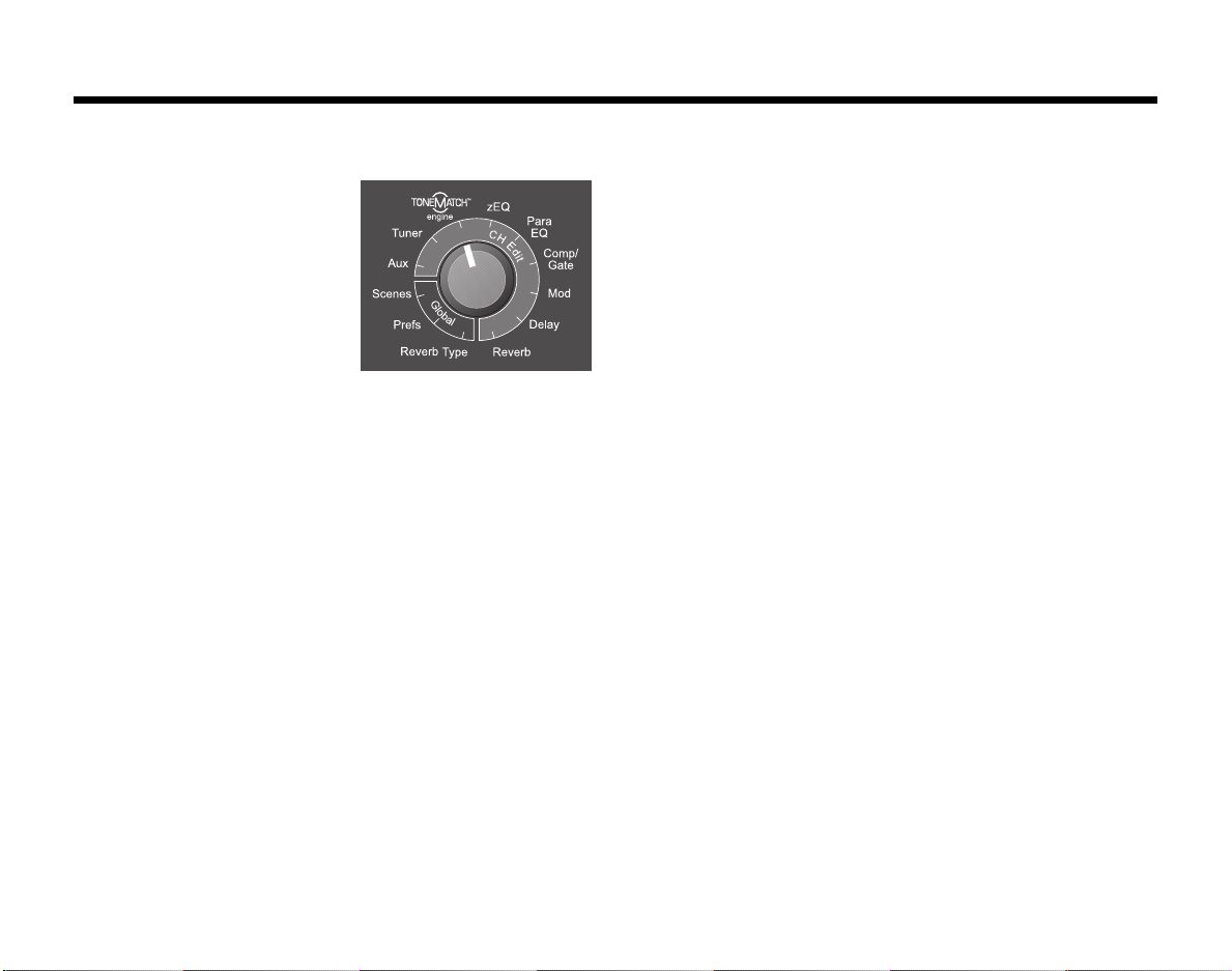
To shape your sound
Rotate the T1 rotary selector to
choose a function.
Use the display information
and control buttons under the
display to change the settings
(see “Reading the T1 display”
on page 18).
1. To n eM atc hTM engine: Select a preset designed for your
specific instrument or microphone (see “Selecting a ToneMatch™ preset” on page 20).
2. zEQ: Adjust the low/mid/high-frequency bands specific to
the selected ToneMatch preset (see “Adjusting zEQ” on
page 21).
3. Para EQ: Fine-tune the equalization (see “Adjusting Para
EQ” on page 21).
4. Comp/Gate: Add some dynamics controls like compression, limiter, or a gate (see “Using compressor/gate functions” on page 22).
5. Mod: Add a modulation effect like chorus or a flanger (see
“Using modulation effects” on page 24).
6. Delay: Add a delay (see “Adding delays” on page 25).
7. Reverb: Add some reverb (see “Adding reverb” on
page 26).
8. Reverb Type: Select a reverb type to affect all channels
(see “Selecting a type of reverb” on page 27).
9. Prefs: View the status display, which shows you the activated effects on each channel (see “Using the Prefs utilities” on page 28).
10. If you like the sound that you have created, turn the T1
rotary selector to Scenes and save your settings as a new
scene. If you don’t like it, try loading one of the five Bose
scenes to use as a new starting point (see “Loading and
saving scenes” on page 32 and “Bose scenes” on
page 37).
The inside of this owner’s guide provides more information on using these features and others not mentioned
here. To get the most out of your T1 ToneMatch audio
engine, please read this owner’s guide.
For additional help, visit www.Bose.com/musicians.
®
iii
Page 4

SAFETY INFORMATION
Please read this owner’s guide
Please take the time to follow the instructions in this owner’s guide carefully. It will help you set up and operate your system
properly and enjoy its advanced features. Please save this owner’s guide for future reference.
WARNING:
•To reduce the risk of fire or electrical shock, do not expose the product to rain or moisture.
The
T1 power supply and the T1 ToneMatchTM audio engine shall not be exposed to dripping or splashing, and objects
•
filled with liquids, such as vases, shall not be placed on the apparatus. As with any electronic products, use care not to
spill liquids into any part of the system. Liquids can cause a failure and/or a fire hazard
• No naked flame sources, such as lighted candles, should be placed on the apparatus.
Notes:
• The product must be used indoors. It is neither designed nor tested for use outdoors, in recreation vehicles, or on boats.
• The product label is located on the bottom of the product.
TM
• The T1 ToneMatch audio engine must be powered only by an L1
model II power stand or a T1 ToneMatch audio engine
power supply.
• The mains plug is used as the disconnect device and should remain readily operable. To completely disconnect the apparatus from the mains, disconnect the mains plug from the mains outlet.
This product conforms to the EMC Directive 89/336/EEC and to the Low Voltage Directive 73/23/EEC. The complete
Declaration of Conformity can be found on www.Bose.com/static/compliance/index.html.
.
EnglishDeutschEspañolFrançaisItalianoNederlandsSvenska Dansk
©2007 Bose Corporation. No part of this work may be reproduced, modified, distributed or otherwise used without prior
written permission.
iv
Page 5

EnglishDeutschEspañolFrançaisItalianoNederlandsSvenska Dansk
Important Safety Instructions
1. Read these instructions.
2. Keep these instructions.
3. Heed all warnings.
4. Follow all instructions.
5. Do not use this apparatus near water.
6. Clean only with a dry cloth.
7. Do not block any ventilation openings. Install in
accordance with the manufacturer’s instructions.
8. Do not install near any heat sources, such as radiators, heat registers, stoves or other apparatus
(including amplifiers) that produce heat.
9. Do not defeat the safety purpose of the polarized or
grounding-type plug. A polarized plug has two
blades with one wider than the other. A groundingtype plug has two blades and a third grounding
prong. The wider blade or third prong is provided
for your safety. If the provided plug does not fit into
your outlet, consult an electrician for replacement
of the obsolete outlet.
10. Protect the power cord from being walked on or
pinched, particularly at plugs, convenience receptacles, and the point where they exit from the apparatus.
11. Only use attachments/accessories specified by the
manufacturer.
12. Use only with the cart, stand, tripod,
bracket or table specified by the manufacturer or sold with the apparatus.
When a cart is used, use caution when
moving the cart/apparatus combination
to avoid injury from tip-over.
13. Unplug this apparatus during lightning storms or
when unused for long periods of time.
14. Refer all servicing to qualified service personnel.
Servicing is required when the apparatus has been
damaged in any way, such as power-supply cord or
plug is damaged, liquid has been spilled or objects
have fallen into the apparatus, the apparatus has
been exposed to rain or moisture, does not operate
normally, or has been dropped.
15. To prevent risk of fire or electric shock, avoid overloading wall outlets, extension cords, or integral
convenience receptacles.
16. Do not let objects or liquids enter the product.
17. See product enclosure bottom for safety related
markings.
18. Use proper power sources.
Information about products that
generate electrical noise
This equipment has been tested and found to comply with the
limits for a Class A digital device, pursuant to Part 15 of the FCC
rules. These limits are designed to provide reasonable protection against harmful interference in a commercial environment.
This equipment generates, uses, and can radiate radio frequency energy and, if not installed and used in accordance with
the instructions, may cause harmful interference to radio communications. Operation of this equipment in a residential area is
likely to cause harmful interference, in which case the user will
be required to correct the interference at his own expense.
This product complies with the Canadian ICES-003 Class A
specifications.
v
Page 6

EnglishDeutschEspañolFrançaisItalianoNederlandsSvenska Dansk
vi
Page 7

SvenskaItalianoFrançaisEspañolDeutschDanskEnglish Nederlands
INTRODUCTION 1
Welcome . . . . . . . . . . . . . . . . . . . . . . . . . . . . . . . . . . . . . . . . . . . . . . . . . . . . . . . . . . . . . . . . . . . . . 1
Product overview . . . . . . . . . . . . . . . . . . . . . . . . . . . . . . . . . . . . . . . . . . . . . . . . . . . . . . . . . . . . . . . 2
Controls and indicators . . . . . . . . . . . . . . . . . . . . . . . . . . . . . . . . . . . . . . . . . . . . . . . . . . . . . . . . . . 3
Connection panel . . . . . . . . . . . . . . . . . . . . . . . . . . . . . . . . . . . . . . . . . . . . . . . . . . . . . . . . . . . . . . 4
SYSTEM SETUP 5
Unpacking . . . . . . . . . . . . . . . . . . . . . . . . . . . . . . . . . . . . . . . . . . . . . . . . . . . . . . . . . . . . . . . . . . . . 5
Removing/attaching the cover . . . . . . . . . . . . . . . . . . . . . . . . . . . . . . . . . . . . . . . . . . . . . . . . . . . . 6
Mounting options . . . . . . . . . . . . . . . . . . . . . . . . . . . . . . . . . . . . . . . . . . . . . . . . . . . . . . . . . . . . . . 7
Connecting the T1 to an L1
Connecting the T1 to an L1 model I power stand . . . . . . . . . . . . . . . . . . . . . . . . . . . . . . . . . . . . . . 12
Connecting the T1 ToneMatch
TM
model II power stand . . . . . . . . . . . . . . . . . . . . . . . . . . . . . . . . . . . . 11
TM
audio engine power supply (optional) . . . . . . . . . . . . . . . . . . . . . 14
Connecting the T1 to your computer . . . . . . . . . . . . . . . . . . . . . . . . . . . . . . . . . . . . . . . . . . . . . . . 15
OPERATING INSTRUCTIONS 16
Optimizing input gain and output volume . . . . . . . . . . . . . . . . . . . . . . . . . . . . . . . . . . . . . . . . . . . . 16
Using the Master volume control . . . . . . . . . . . . . . . . . . . . . . . . . . . . . . . . . . . . . . . . . . . . . . . . . . 17
Muting a channel . . . . . . . . . . . . . . . . . . . . . . . . . . . . . . . . . . . . . . . . . . . . . . . . . . . . . . . . . . . . . . . 17
Muting channel effects . . . . . . . . . . . . . . . . . . . . . . . . . . . . . . . . . . . . . . . . . . . . . . . . . . . . . . . . . . 17
Reading the T1 display . . . . . . . . . . . . . . . . . . . . . . . . . . . . . . . . . . . . . . . . . . . . . . . . . . . . . . . . . . 18
Using the T1 rotary selector . . . . . . . . . . . . . . . . . . . . . . . . . . . . . . . . . . . . . . . . . . . . . . . . . . . . . . 19
Editing the sound of a channel . . . . . . . . . . . . . . . . . . . . . . . . . . . . . . . . . . . . . . . . . . . . . . . . . . . . 20
Selecting a ToneMatch
Adjusting zEQ . . . . . . . . . . . . . . . . . . . . . . . . . . . . . . . . . . . . . . . . . . . . . . . . . . . . . . . . . . . . 21
Adjusting Para EQ . . . . . . . . . . . . . . . . . . . . . . . . . . . . . . . . . . . . . . . . . . . . . . . . . . . . . . . . . 21
Using compressor/gate functions . . . . . . . . . . . . . . . . . . . . . . . . . . . . . . . . . . . . . . . . . . . . . 22
Using the KickGate . . . . . . . . . . . . . . . . . . . . . . . . . . . . . . . . . . . . . . . . . . . . . . . . . . . . . . . . 23
Using modulation effects . . . . . . . . . . . . . . . . . . . . . . . . . . . . . . . . . . . . . . . . . . . . . . . . . . . . 24
Adding delays . . . . . . . . . . . . . . . . . . . . . . . . . . . . . . . . . . . . . . . . . . . . . . . . . . . . . . . . . . . . 25
Adding reverb . . . . . . . . . . . . . . . . . . . . . . . . . . . . . . . . . . . . . . . . . . . . . . . . . . . . . . . . . . . . 26
Routing input signals to the Aux output . . . . . . . . . . . . . . . . . . . . . . . . . . . . . . . . . . . . . . . . 26
Using the tuner . . . . . . . . . . . . . . . . . . . . . . . . . . . . . . . . . . . . . . . . . . . . . . . . . . . . . . . . . . . 27
TM
preset . . . . . . . . . . . . . . . . . . . . . . . . . . . . . . . . . . . . . . . . . . . . . . 20
vii
Page 8

EnglishDeutschEspañolFrançaisItalianoNederlandsSvenska Dansk
Using global functions . . . . . . . . . . . . . . . . . . . . . . . . . . . . . . . . . . . . . . . . . . . . . . . . . . . . . . . . . . . 27
Selecting a type of reverb . . . . . . . . . . . . . . . . . . . . . . . . . . . . . . . . . . . . . . . . . . . . . . . . . . . 27
Using the Prefs utilities . . . . . . . . . . . . . . . . . . . . . . . . . . . . . . . . . . . . . . . . . . . . . . . . . . . . . 28
Loading and saving scenes . . . . . . . . . . . . . . . . . . . . . . . . . . . . . . . . . . . . . . . . . . . . . . . . . . 32
Sharing a scene . . . . . . . . . . . . . . . . . . . . . . . . . . . . . . . . . . . . . . . . . . . . . . . . . . . . . . . . . . . 35
Bose scenes . . . . . . . . . . . . . . . . . . . . . . . . . . . . . . . . . . . . . . . . . . . . . . . . . . . . . . . . . . . . . . . . . . 37
Factory Settings . . . . . . . . . . . . . . . . . . . . . . . . . . . . . . . . . . . . . . . . . . . . . . . . . . . . . . . . . . . 37
Singer/Songwriter . . . . . . . . . . . . . . . . . . . . . . . . . . . . . . . . . . . . . . . . . . . . . . . . . . . . . . . . . 38
DJ/Playback . . . . . . . . . . . . . . . . . . . . . . . . . . . . . . . . . . . . . . . . . . . . . . . . . . . . . . . . . . . . . . 40
Drums and Bass . . . . . . . . . . . . . . . . . . . . . . . . . . . . . . . . . . . . . . . . . . . . . . . . . . . . . . . . . . 42
The Works scene . . . . . . . . . . . . . . . . . . . . . . . . . . . . . . . . . . . . . . . . . . . . . . . . . . . . . . . . . . 44
FACTORY SETTINGS 46
CARE & MAINTENANCE 48
Cleaning . . . . . . . . . . . . . . . . . . . . . . . . . . . . . . . . . . . . . . . . . . . . . . . . . . . . . . . . . . . . . . . . . . . . . . 48
Limited Warranty and Registration . . . . . . . . . . . . . . . . . . . . . . . . . . . . . . . . . . . . . . . . . . . . . . . . . 48
Accessories . . . . . . . . . . . . . . . . . . . . . . . . . . . . . . . . . . . . . . . . . . . . . . . . . . . . . . . . . . . . . . . . . . . 48
Troubleshooting . . . . . . . . . . . . . . . . . . . . . . . . . . . . . . . . . . . . . . . . . . . . . . . . . . . . . . . . . . . . . . . . 48
Technical information . . . . . . . . . . . . . . . . . . . . . . . . . . . . . . . . . . . . . . . . . . . . . . . . . . . . . . . . . . . 53
viii
Page 9

Welcome
EnglishDeutschEspañolFrançaisItalianoNederlandsSvenska Dansk
INTRODUCTION
Thank you for purchasing the Bose® T1 ToneMatch™ audio engine. The T1 ToneMatch™ audio engine provides the
ultimate control for performing musicians. When used with the Bose L1™ model II or model I system, the T1 allows
you to control the sound of your instrument as well as the output of the entire system. Using proprietary ToneMatch
presets and associated zEQ tonal adjustments, the T1 enables you to preserve the natural sound of instruments or
vocal microphones when amplified. Designed by musicians, for musicians, the Bose T1 ToneMatch™ audio engine
is contained in a small, portable enclosure that you can keep beside you during a performance.
Features and benefits
• Quick and easy-to-use interface
• One-cable connection to L1™ model II loudspeaker ToneMatch™ port
• Mountable on a Cylindrical Radiator
• High-quality, low-noise preamps in each channel, allowing the use of almost any instrument or microphone
• LED display and illuminated controls for playing on dimly-lit stages
• ToneMatch presets, a proprietary technology that optimizes system equalization to preserve the natural sound of
specific instruments or microphones
• zEQ, working in conjunction with the ToneMatch technology, automatically adjusts the low, mid, and high
frequency bands for the selected preset, allowing further tonal shaping
• Built-in chromatic tuner
• Performance scenes that can be saved and recalled
• Two flexible analog outputs
• System updates and ToneMatch presets available at www.Bose.com/musicians
• USB audio interface to your computer
• Compatible with L1
TM
model I and model II systems
®
loudspeaker or a microphone stand
For more information
This owner’s guide provides only basic setup and operating instructions. For more in-depth information on using
this system, including tips, techniques, and frequently asked questions, please visit www.Bose.com/musicians.
1
Page 10
INTRODUCTION
Product overview
The T1 ToneMatchTM audio engine can be used with a Bose® L1TM model II or model I system. For convenient
access, you can mount the T1 on a Cylindrical Radiator® loudspeaker or on a microphone stand using the optional
microphone stand bracket. When used with the L1
the power stand. The optional T1 ToneMatchTM audio engine power supply is used to power the T1 when it is connected to an L1TM model I system or a USB port on your computer.
EnglishDeutschEspañolFrançaisItalianoNederlandsSvenska Dansk
TM
model II system, the T1 operates on DC power received from
Figure 1
T1
ToneMatch
TM
audio engine
and
accessories
T1 ToneMatchTM audio engine
and the L1 model II system
T1 ToneMatchTM
audio engine
L1TM model II
system
To order accessories, call (800) 905-0886 or visit www.Bose.com/musicians.
Optional accessories
T1 ToneMatchTM audio engine
power supply
To ne M at chTM audio engine
microphone stand bracket
2
Page 11
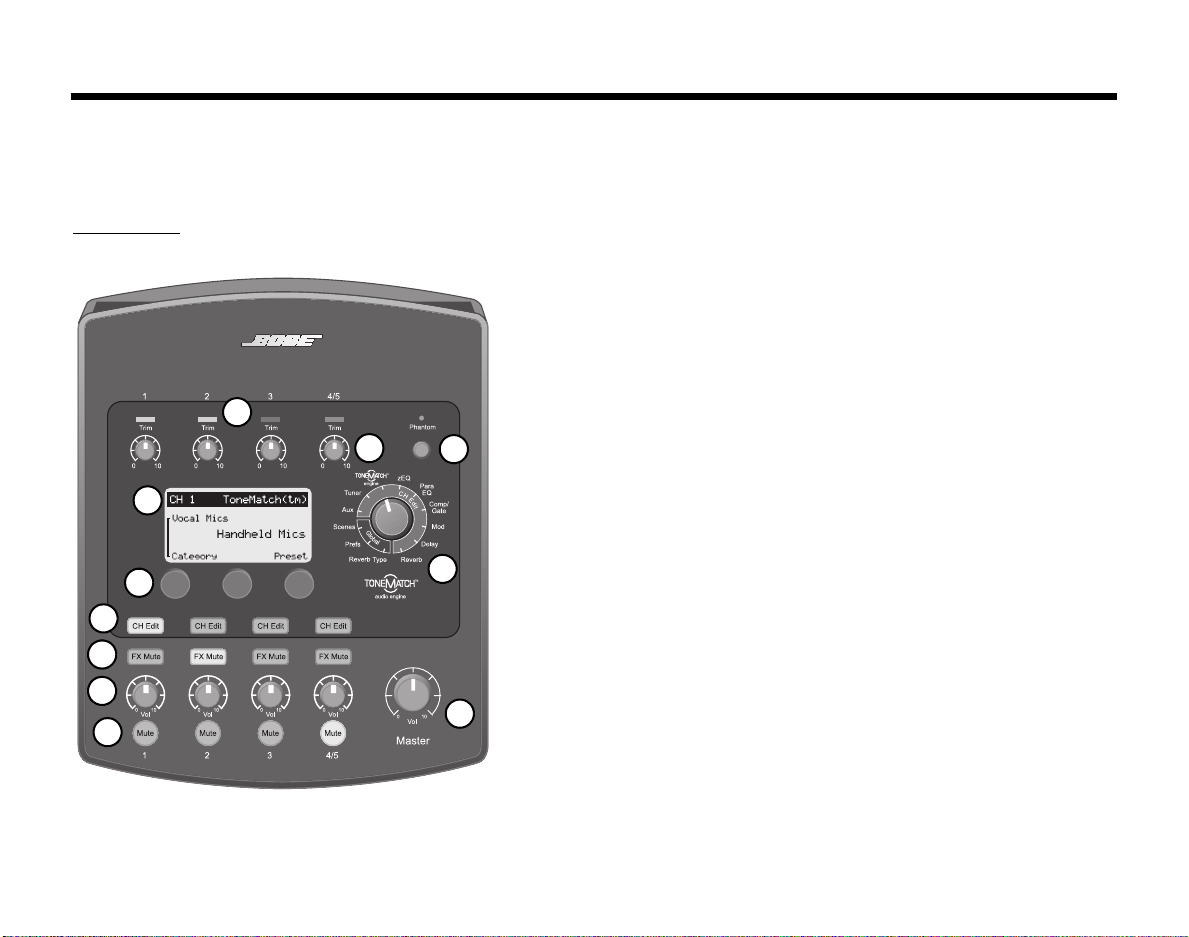
Controls and indicators
The control panel provides all the necessary controls and indicators for operation.
Figure 2
Top panel
1
2
11
10
9
8
7
6
SvenskaItalianoFrançaisEspañolDeutschDanskEnglish Nederlands
INTRODUCTION
1. Input signal/clip LEDs (1-4/5) – Displays the input signal status in
color: Green indicates the presence of an input signal, yellow indicates
a signal near clipping, and red indicates clipping.
2. Trim controls (1-4/5) – Adjusts the input sensitivity for the respective
channel.
3. Phantom power switch – Applies +48V power to input channels 1-3.
A red LED indicates that phantom power is on.
3
4
4. T1 rotary selector – Allows access to both global and channelrelated parameters, which are adjusted using the editing controls.
5. MASTER volume control – Adjusts the overall output level.
6. Mute buttons (1-4/5) – Silences the audio output for the respective
channel.
7. Volume controls (1-4/5) – Adjusts the volume level for the respective
channel.
8. FX mute buttons (1-4/5) – Bypasses the Mod, Delay, and Reverb
effects on the selected channel.
9. CH Edit buttons (1-4/5) – Selects the channel you want to modify
using the T1 rotary selector and display-related editing controls.
10. Editing controls – These three rotary/push-button controls allow you
to select or adjust items/values appearing on the display.
11. Display – Provides function menus and system status information.
5
3
Page 12
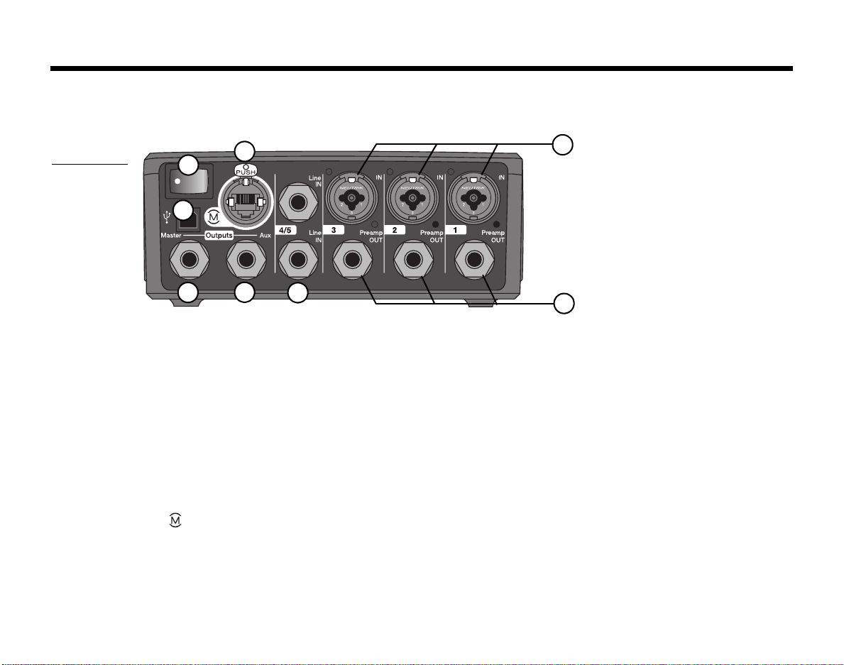
INTRODUCTION
Connection panel
The rear panel provides all input/output connections.
Figure 3
T1 connector
panel
7
6
EnglishDeutschEspañolFrançaisItalianoNederlandsSvenska Dansk
8
1
5
4
3
2
1. IN – Analog input channels 1-3. Accepts XLR balanced cables for microphones, or ¼" TRS balanced or TS
unbalanced cables for high-impedance inputs such as guitars.
2. Preamp OUT – Preamp outputs for channels 1-3. Accepts ¼" TRS balanced or TS unbalanced cables.
3. Line IN – Analog input channels 4/5. Accepts ¼" TRS balanced or TS unbalanced cables for line-level inputs.
Can be used for stereo input signals.
4. Aux Output – User-definable analog output. Can be configured for a pre-fader, post-EQ, and effects, or postfader output. Accepts ¼" TRS balanced or TS unbalanced cables.
5. Master Output – User-definable analog output. Can be configured for a pre- or post-Master volume analog
output. Accepts ¼" TRS balanced or TS unbalanced cables.
6. USB port – A USB interface that allows you to connect the T1 to your computer. This feature enables you to
stream audio to/from your computer, update the T1, and back up performance scenes.
7. Power switch – Turns the T1 audio engine on or off.
8. – Tone M at ch
audio engine from the L1 model II power stand. Accepts the included ToneMatch
CAUTION: Although the ToneMatch port accepts a standard RJ-45 connector, DO NOT connect the T1 to a computer
TM
port – A digital output used by the L1TM model II system. Also delivers power to the T1
TM
cable.
or phone network.
4
Page 13
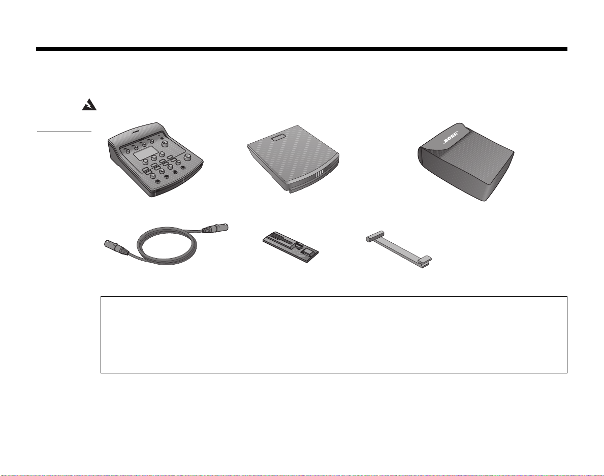
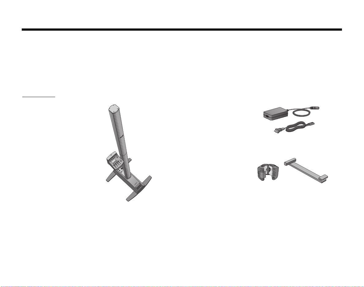
Unpacking
Figure 4
Parts list
EnglishDeutschEspañolFrançaisItalianoNederlandsSvenska Dansk
SYSTEM SETUP
The items packed in the carton are shown in Figure 4. Carefully unpack the carton and check that you have all the
items shown here. Keep all packing materials for possible future use.
WARNING: To avoid danger of suffocation, keep the plastic bags out of the reach of children.
T1 ToneMatchTM audio engine
ToneMatch
TM
cable Carriage Mounting bar
Cover
Carrying case
Serial numbers and product registration
Now is a good time to record the serial number of your T1 ToneMatchTM audio engine here and on your product
registration card.
to do so will not affect your warranty rights.
Serial Number: __________________________________________________________
You can register your product online at www.Bose.com/register or call (800) 905-1044. Failure
5
Page 14
EnglishDeutschEspañolFrançaisItalianoNederlandsSvenska Dansk
C
SYSTEM SETUP
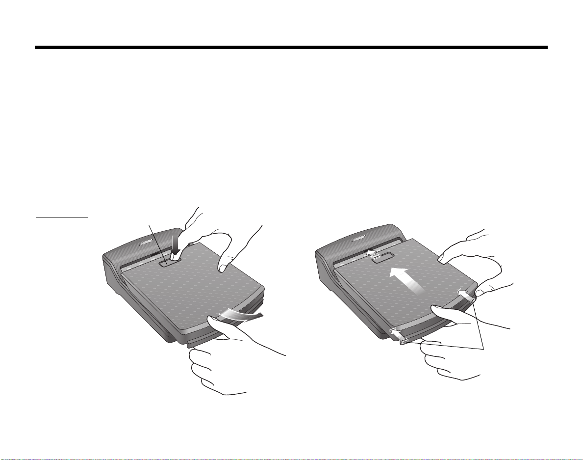
Removing/attaching the cover
The T1 ToneMatchTM audio engine comes out of the carton with a cover installed on the top panel. The cover is
designed to protect the control panel while transporting or storing the audio engine.
To remove the cover:
1. Press and hold the cover latch release button (Figure 5).
2. Slide the cover off the control panel just enough to disengage the alignment tabs.
3. Lift up on the front edge of the cover to remove it.
To attach the cover:
1. Place the cover on the T1.
2. Align the tabs inside the cover with the holes on the front edge of the T1.
3. Slide the cover over the control panel until you hear the click of the latch.
Figure 5
Removing and
attaching the
cover
over latch
release button
Alignment tabs
(front edge)
6
Page 15
Mounting options
The T1 includes hardware for mounting it on a Cylindrical Radiator® loudspeaker.
The optional microphone stand mounting bracket allows you to mount the T1 on the shaft of most microphone
stands. See “Mounting the T1 on a microphone stand (optional)” on page 9.
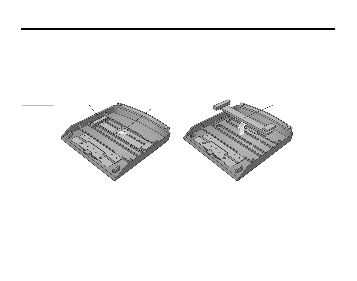
Mounting the T1 on a Cylindrical Radiator® loudspeaker
Use the carriage and mounting bar included in the carton to mount the T1 on the Cylindrical Radiator® loudspeaker.
The mounting bar is stored inside the T1 cover (Figure 6). Open the latch and lift the mounting bar from the case.
Figure 6
Removing
mounting bar
from cover
Mounting bar
Latch
SvenskaItalianoFrançaisEspañolDeutschDanskEnglish Nederlands
SYSTEM SETUP
Mounting bar
7
Page 16
SYSTEM SETUP
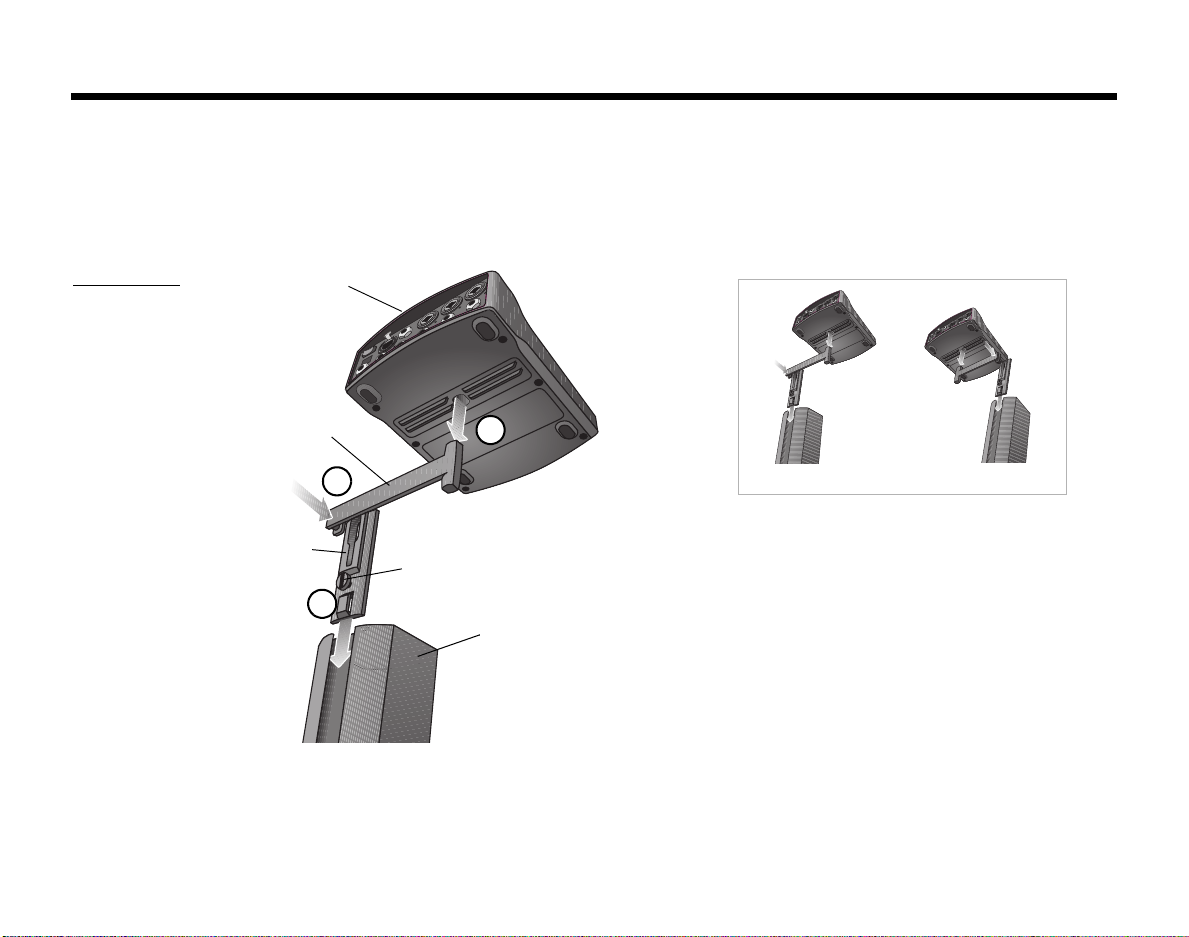
Figure 7
T1 mounted on
a Cylindrical
®
Radiator
loudspeaker
EnglishDeutschEspañolFrançaisItalianoNederlandsSvenska Dansk
The Cylindrical Radiator® top section needs to be removed for this installation.
1. Slide the carriage into the channel on the rear of the Cylindrical Radiator® bottom section and turn the locking
knob clockwise to lock it in place (Figure 7).
2. Insert the mounting bar into the slot in the carriage and push it downward.
3. Place the T1 on the mounting bar.
T1 ToneMatch
TM
audio engine
Mounting
3
bar
2
The T1 can be mounted to the left or right.
Carriage
Locking knob
1
Cylindrical
Radiator
bottom section
8
®
Page 17
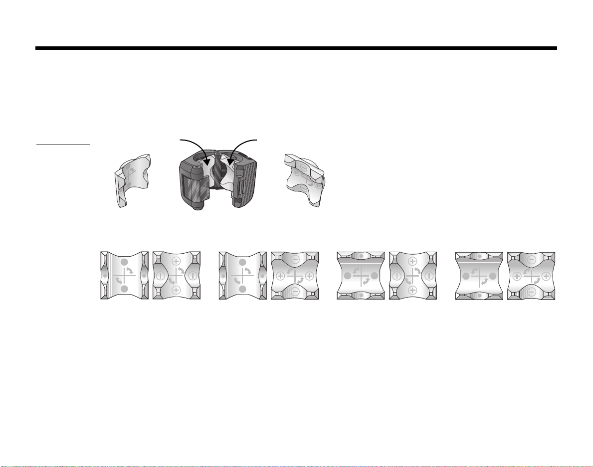
Figure 8
Bracket and
insert
placements
SvenskaItalianoFrançaisEspañolDeutschDanskEnglish Nederlands
SYSTEM SETUP
Mounting the T1 on a microphone stand (optional)
The T1 ToneMatchTM audio engine microphone stand bracket allows you to mount the T1 on the shaft of most
microphone stands. For installation help, refer to the Quick Setup Guide that came with the bracket.
The bracket uses rotatable inserts which, when properly placed, provide a tight fit on the microphone stand shaft.
Figure 8 shows insert placements for some common shaft diameters. You may need to arrange these inserts differently for your particular music stand.
Removable insert
A
For 22 mm diameter For 20.5 mm diameter For 16 mm diameter For 14.5 mm diameter
AB
Removable insert
B
AB
AB
AB
9
Page 18
SYSTEM SETUP
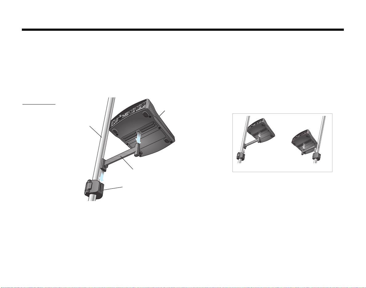
Figure 9
Mounting the
T1 on a
microphone
stand
EnglishDeutschEspañolFrançaisItalianoNederlandsSvenska Dansk
To install the microphone stand bracket:
1. Determine the diameter of the shaft on your microphone stand. The cutouts on the edge of the Microphone
Stand Bracket Quick Setup Guide can help you determine the diameter.
2. Remove the inserts (Figure 8 on page 9) from the bracket and re-insert them for the diameter you need.
3. Attach the microphone stand bracket to the microphone stand (Figure 9).
4. Attach the mounting bar to the microphone stand bracket.
5. Place the T1 on the mounting bar.
T1 ToneMatchTM
audio engine
Microphone
stand
10
Mounting bar
The T1 can be mounted to the left or right.
Microphone stand bracket
Page 19
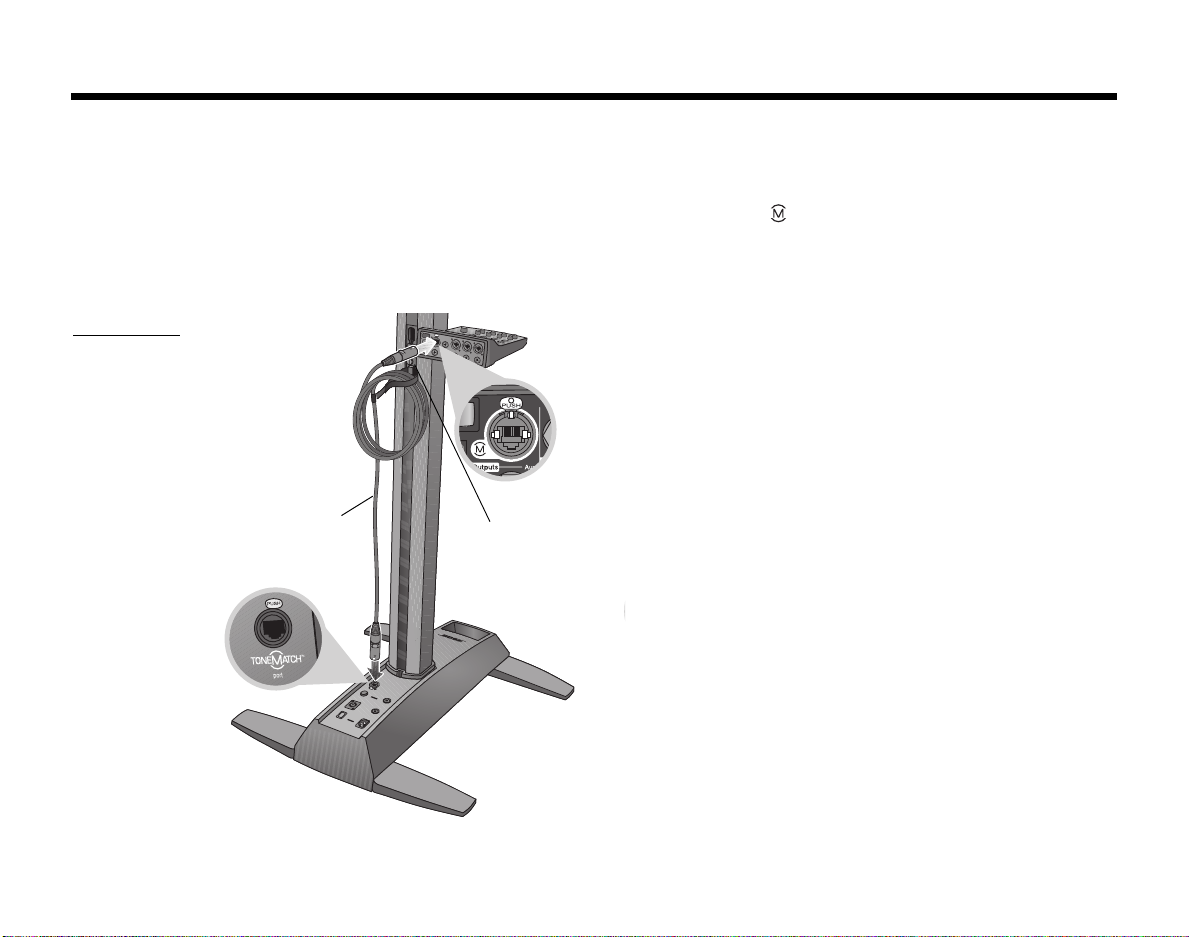
Connecting the T1 to an L1TM model II power stand
Power / Fault
1. Make sure the power stand Power switch is OFF, the T1 power switch is OFF, and the T1 Master volume
control is set to 0.
TM
cable into the ToneMatchTM port ( ) on the T1. Plug the other end of the
Figure 10
L1TM model II
connections to
a T1
2. Plug one end of the ToneMatch
To ne M at ch
TM
cable into the Tone M a tc hTM port on the power stand.
3. Turn on the T1 audio engine and then turn on the L1 model II power stand.
4. Connect your instruments and adjust levels. Refer to “Optimizing input gain and output volume” on page 16.
SvenskaItalianoFrançaisEspañolDeutschDanskEnglish Nederlands
SYSTEM SETUP
ToneMatch
cable
Hook-and-loop strap
hanging excess cable
on the carriage
11
Page 20

SYSTEM SETUP
Connecting the T1 to an L1 model I power stand
On an L1TM model I power stand, the Channel 1 and Channel 2 Mic/Line inputs have independent volume, equalization, and ToneMatch
Master output should be connected to either the Channel 3 or Channel 4 Line IN connectors. The R1 remote control should be disconnected so that the T1 provides the master volume control for the system.
If you want to connect additional sources to the Channel 1 and Channel 2 Mic/Line inputs on the L1 model I power
stand, the R1 remote control must be connected. However, the R1 remote control then will control the master volume of the L1 system, not the T1 audio engine.
To connect the T1 (as master volume control) to an L1 model I system:
1. Make sure the Power switch on the power stand is in the OFF position and the R1 remote control is disconnected.
2. Make sure the T1 power switch is in the OFF position and the T1 audio engine power supply is connected.
See “Connecting the T1 ToneMatch
3. Make sure the T1 Master volume control is set to 0.
4. Plug one end of a ¼" unbalanced TS audio cable (not supplied) into the T1 Master output port. Plug the other
end of the ¼" cable into the Channel 3 (or Channel 4) Line IN connector on the L1 power stand.
5. Set the Line IN Level control on the power stand to approximately 2.
In some circumstances, you may need to slightly adjust the Line IN Level control from this initial setting to
attain the desired gain structure.
6. Turn on the T1 audio engine.
7. Turn on the L1 model I power stand.
8. Connect your instruments and adjust levels. Refer to “Optimizing input gain and output volume” on page 16.
TM
preset controls that can affect the sound of the T1 audio engine. For this reason, the T1
TM
audio engine power supply (optional)” on page 14 for more details.
EnglishDeutschEspañolFrançaisItalianoNederlandsSvenska Dansk
12
Page 21

Figure 11
L1TM model I
connections to
a T1
SvenskaItalianoFrançaisEspañolDeutschDanskEnglish Nederlands
SYSTEM SETUP
¼" audio cable
(not supplied)
T1 ToneMatchTM
power supply
(optional)
Channel 3 & 4 input
and Level control
Note: To avoid problems caused by ground loops, connect the power stand and the T1 power supply to the same AC
mains circuit.
13
Page 22

SYSTEM SETUP
Connecting the T1 ToneMatchTM audio engine power supply (optional)
The T1 power supply provides power for the T1 audio engine when connecting it to an L1TM model I system or your
computer.
TM
1. Plug the power supply cable into the T1 ToneMatch
2. Plug one end of the AC power cord into the power supply.
3. Plug the other end of the power cord into a live AC (mains) outlet.
4. Switch the T1 power switch to the ON position.
Figure 12
T1 power
supply
connections
port.
EnglishDeutschEspañolFrançaisItalianoNederlandsSvenska Dansk
14
AC power cord
3
T1 ToneMatchTM
audio engine
T1 power
supply
ToneMatch port
4
1
Power supply cable
2
Page 23

Connecting the T1 to your computer
The T1 provides a USB port for connecting it to a computer. This allows you to download performance scenes to a
computer or install system updates. Visit www.Bose.com/musicians for details on updating your system.
When connected to a computer, you also can use the T1 as a general-purpose USB audio device for recording and
playback.
Note: The T1 operates at 48kHz/24-bit. When using the T1 with recording software, you may need to configure the
software settings for 48kHz/24-bit operation.
Connecting the T1 to your computer requires a USB cable (Type A to Type B, not supplied).
1. Connect the T1 audio engine either to your L1 model II system or a T1 power supply (see “Connecting the T1
To ne M at ch
2. Plug one end of the USB cable into the T1 audio engine USB port (Figure 13).
3. Plug the other end of the USB cable into a USB port on your computer.
4. Turn on the T1 audio engine.
Figure 13
T1-to-USB
connection
TM
audio engine power supply (optional)” on page 14).
SvenskaItalianoFrançaisEspañolDeutschDanskEnglish Nederlands
SYSTEM SETUP
ToneMatch port – To an L1 model II system
or a T1 ToneMatch power supply.
Power switch
To
computer
USB port
USB cable
(Type A to Type B)
15
Page 24

OPERATING INSTRUCTIONS
IMPORTANT!
Optimizing input gain and output volume
Getting a quality volume level from your system relies on the combined adjustments of input channel gain, master
volume, and channel volume. Do the following for each channel used.
1. Make sure the Master volume, Trim, and channel volume controls are set to 0.
2. Adjust input channel Trim.
A. If applicable, adjust the volume of your instrument/source to the desired level.
B. Play your instrument/source at a performance level.
C. Slowly turn the Trim control clockwise until the signal/clip indicator glows green or just starts to flash
yellow. If the indicator flashes red or glows steady red, turn the Tr im control counter-clockwise to
decrease the level.
D. Use the input level meters (page 29) in the Prefs menu to check your input levels.
(Example)
Note: If you are using a device that requires phantom power (+48V), such as a condenser microphone, depress
the Phantom power switch before adjusting the Tri m control.
Note: The input level meter in the Prefs menu can be helpful when adjusting the input Trim level (see page 29).
Input Level Preferences
CH1 . . . . . . . . . . . . .
CH2 . . . . . . . . . . . . .
CH3 . . . . . . . . . . . . .
CH 4/5 . . . . . . . . . . . . .
Menu Reset
EnglishDeutschEspañolFrançaisItalianoNederlandsSvenska Dansk
Peak level
indicator
Input level
indicator
16
3. Set the Master volume control at the 12 o’clock position.
4. Slowly turn the channel volume control clockwise until the volume reaches the desired level.
Page 25

Using the Master volume control
The Master volume control adjusts the overall output level of the T1 ToneMatchTM output ( ) and analog Master
output. During normal operation, it is recommended to keep the Master control set at the 12 o’clock position.
Once you have set volume levels for all channels, you can adjust the Master volume up or down from this position.
Muting a channel
The Mute buttons silence the audio for the respective channel.
• To mute a channel, press the Mute button once. The Mute button glows bright blue to indicate that the channel
is muted.
•Press the Mute button again to unmute the channel. The Mute button dims to indicate that the channel is not
muted.
Muting channel effects
The FX Mute 1-4/5 buttons mutes only the Mod, Delay, and Reverb effects on the respective channel. Muting
effects does not bypass ToneMatch presets, zEQ, Para EQ, and Comp/Gate settings.
• To mute effects on a channel, press the FX Mute button once. The FX Mute button glows bright blue to indicate
that the channel effects are muted.
•Press the FX Mute button again to unmute the channel effects. The FX Mute button dims to indicate that the
channel effects are not muted.
Note: If the T1 rotary selector is set to Mod, Delay, or Reverb, the message “FX Mute is Active” appears on
the display.
SvenskaItalianoFrançaisEspañolDeutschDanskEnglish Nederlands
OPERATING INSTRUCTIONS
17
Page 26

OPERATING INSTRUCTIONS
Reading the T1 display
The display provides you with an interface for operating the audio engine. Figure 14 shows you a sample of display
information and the basic operating conventions. The content of the display depends on the T1 rotary selector
position.
EnglishDeutschEspañolFrançaisItalianoNederlandsSvenska Dansk
Figure 14
Sample display
and operating
conventions
Identifies the
selected channel
This symbol indicates that
you rotate the button to
change the setting
Asterisk indicates that
the loaded scene was
modified
Indicates that you press the button
to access the top parameter
CH 1 Delay
Fdbk.
Type Mix Time
Analog 30% 150ms
Rotary/pushbutton
controls
All Channels Scenes
*Bose Scene 01
Load Shared Save
Identifies the function accessed
by the T1 rotary selector
Parameter names and
their settings/values
Indicates that you
rotate the button to
change the value
Indicates that you press
the button to activate the
function
18
Page 27

Using the T1 rotary selector
The T1 rotary selector provides access to the functions that shape the sound of the ToneMatchTM audio engine output. Figure 15 provides a summary of the three global functions and the nine channel-related functions. The following pages describe how to adjust each function.
Figure 15
Rotary selector
To n eM at ch
TM
engine
Provides access to proprietary ToneMatch
presets designed for specific instruments
and microphones.
Tuner
Provides tuning information
for an instrument playing
into the selected channel.
Sends a selected channel
to the Aux output.
Global
Allows you to save and load
performance scenes (a snapshot
of the complete state of the unit).
Allows access to several
Applies a selected type
of reverb to all channels.
Scenes
Prefs
system utilities.
Reverb Type
Aux
SvenskaItalianoFrançaisEspañolDeutschDanskEnglish Nederlands
OPERATING INSTRUCTIONS
zEQ
As part of the selected ToneMatch preset,
provides controls to adjust low/mid/high
frequencies that are within the range of
your instrument or microphone.
Para EQ
Provides Level, Frequency, and
Width parametric EQ controls for
a single band.
Comp/Gate
Provides gate, compression, limiter, de-esser, and kick drum presets with adjustable parameters.
Mod
Provides several modulation
effects such as chorus,
flanger, phaser, and tremolo.
Delay
Provides three types of
delays.
Reverb
Applies reverb to a selected
channel.
19
Page 28

OPERATING INSTRUCTIONS
Editing the sound of a channel
The CH Edit functions allow access to settings that affect selected channels. The CH Edit functions are Aux, Tuner,
ToneMatch the engine, zEQ, Para EQ, Comp/Gate, Mod, Delay, and Reverb.
To edit a channel:
1. Press the CH Edit 1, 2, 3, or 4/5 button. The CH Edit button glows blue, indicating that the channel is
enabled for editing.
2. Select one of the CH Edit functions using the T1 rotary selector.
3. Adjust the settings for that function using the following instructions.
Note: You can only edit one channel at a time. Pressing a CH Edit button enables editing only for the selected channel.
All other CH Edit buttons are dimmed to indicate they are inactive.
Selecting a ToneMatch™ preset
The ToneMatchTM engine function allows you to select a ToneMatch preset for your instrument or microphone. This
proprietary technology optimizes system equalization to preserve the natural sound of your specific instrument or
microphone. They are organized into categories and independently selected for each channel.
Note: To bypass the selected ToneMatch preset, press the Category button. Press it again to activate.
1. Rotate the Category button to access the list of categories and highlight your choice.
EnglishDeutschEspañolFrançaisItalianoNederlandsSvenska Dansk
20
CH 1 ToneMatch(tm)
Utility
Flat
Category Preset
Rotate
Utility
Vocal Mics
Electric Guitars
Acoustic Guitars
Select Cancel
Press
2. Press the Select button to select your choice, or press the Cancel button to exit the list with no change.
Page 29

SvenskaItalianoFrançaisEspañolDeutschDanskEnglish Nederlands
OPERATING INSTRUCTIONS
3. If you pressed Select, rotate the Preset button to access the list of presets and highlight your choice.
CH 1 ToneMatch(tm)
Vocal Mics
Handheld Mics
Category Preset
Rotate
Handheld Mics
Headworn
High Gain: Bright
Cancel Select
Press
CH 1 ToneMatch(tm)
Vocal Mics
Handheld Mics
Category Preset
4. Press the Select button to select your choice, or press the Cancel button to exit the list with no change.
Adjusting zEQ
The zEQ function is part of the ToneMatchTM preset technology. It allows you to adjust
low/mid/high frequencies that are within the range of your instrument or microphone.
To adjust zEQ, rotate the button under the corresponding frequency band.
Note: To bypass an individual frequency band, press the corresponding button. Press it
CH 1 zEQ
Handheld Mics
Low Mid High
0dB 0dB 0dB
again to activate.
Adjusting Para EQ
CH 1 Parametric EQ
The Para EQ function provides parametric equalization centered on a user-specified
frequency within the range of 50 Hz to 8000 Hz.
Note: To bypass the Para EQ settings, press the Level button. Press it again to activate.
Level Freq Width
0dB 1000Hz 1.00oct
1. Rotate the Level button to adjust the boost/cut level from +15 dB to –15 dB.
2. Rotate the Freq button to adjust the center frequency from 50 Hz to 8000 Hz.
3. Rotate the Width button to adjust the width of the bell curve around the center
frequency from 0.20 octave to 5.00 octave.
21
Page 30

OPERATING INSTRUCTIONS
EnglishDeutschEspañolFrançaisItalianoNederlandsSvenska Dansk
Using compressor/gate functions
CH 1 Comp/Gate
The Comp/Gate function provides access to gate, compression, limiter, de-esser and
kick drum presets with adjustable parameters.
Note: To bypass the Comp/Gate settings, press the Type button. Press it again to
Type Thresh Speed
Gate –80.0dB 50%
activate.
1. Rotate the Typ e button to access the list of Comp/Gate effects and highlight
your choice:
Compressor 1: Light........ Compressor featuring a preset low-compression ratio with variable threshold and
gain parameters. Works well as a general-purpose compressor for most instruments
and microphones that require minimal level control.
Compressor 1: Medium... Compressor featuring a preset moderate compression ratio with variable threshold
and gain parameters. Works well with basses, guitars, keyboards, and vocals
requiring subtle level control.
Compressor 1: Heavy...... Compressor featuring a preset high compression ratio with variable threshold and
gain parameters. Works well with loud instruments – like horns and drums, as well
as strong vocals that require more aggressive level control.
Limiter..............................Hard limiter featuring a preset ratio (
∞:1) with variable threshold and gain parame-
ters. Works well with very loud instruments, such as drums, to prevent signal peaks
from overloading the channel.
De-Esser .......................... Side-chained compressor featuring a preset compression ratio with variable
threshold and gain parameters. Designed to reduce sibilance on vocals.
Noise Gate....................... Noise gate with a fast preset attack time, variable threshold, and variable speed
(release time). Well-suited for eliminating unwanted noise from microphones and
instruments.
KickGate 1: Regular......... Gate featuring a preset attack time, and variable threshold and tightness (release
time) parameters. This is a Bose
®
proprietary technology designed specifically for
kick drums. This robust gate provides maximum gain before feedback, making your
kick drum as loud as possible through an L1TM system.
KickGate 2: Fast .............. Same as KickGate 1 – but adjusted for faster tempos. Select this setting if you are
using a double bass drum pedal.
22
Page 31

SvenskaItalianoFrançaisEspañolDeutschDanskEnglish Nederlands
OPERATING INSTRUCTIONS
2. Press the Select button to select your choice, or press the Cancel button to exit the list with no change.
3. For Comp1-3, Limiter, De-Ess: Rotate the Thresh button to adjust the input threshold (trigger) level from
-50dB to 0dB. Rotate the Gain button to adjust the gain from 0dB to 30.0dB. The gain bar above the button
shows the amount of gain reduction. This display helps in setting the threshold.
For Gate: Rotate the Thresh button to adjust the input threshold (trigger) level from -90dB to -30dB. Rotate
the Speed button to set the gate closing speed to any value from 0 (fastest) to 100% (slowest).
For Kick1-2: Rotate the Thresh button to adjust the input threshold (trigger) level from -20dB to 0dB. Rotate
the Tight button to adjust the tightness (how quickly the gate closes) from 0 (slowest) to 100% (fastest).
Using the KickGate
The KickGate is a Bose® proprietary technology that allows you to raise the level of a kick drum channel while eliminating the risk of feedback from the microphone. Two KickGate settings are available in the Comp/Gate menu.
1. Connect the appropriate type of microphone.
2. Select an appropriate ToneMatch
3. Adjust the channel input Trim control so that the hardest kick drum hits turn the input channel LED yellow, but
not red.
4. Select Comp/Gate with the T1 rotary selector.
5. Rotate the Typ e button to scroll down the list, highlight KickGate 1 or KickGate 2, and press Select.
Choose KickGate 2 when using a double bass drum pedal.
6. While playing the kick drum, increase the volume to the desired performance level.
7. Play the kick drum at the softest level you intend to use in the performance and check that you can hear it.
8. While playing softly, increase the Thresh level until some of the kick drum hits get cut off. Then lower the
Thresh level by 3dB.
9. While playing the kick drum normally, rotate the Tight button counter-clockwise to reduce the tightness and
add more “boom” to the sound. Tightness can be adjusted from 0 (slowest) to 100% (fastest).
TM
preset.
23
Page 32

OPERATING INSTRUCTIONS
EnglishDeutschEspañolFrançaisItalianoNederlandsSvenska Dansk
Using modulation effects
CH 1 Modulator
The Mod function allows you to apply modulation effects.
Note: To bypass the Mod settings, press the Type button. Press it again to activate.
1. Rotate the Typ e button to access the list of modulator types and highlight your
Type Mix Depth
Chorus1 50% 50%
choice:
Chorus 1: Brite............... Wet, shimmering chorus that works well with acoustic
instruments. Includes adjustable mix, depth, and speed
parameters.
Chorus 2: Warm............. Similar to Chorus 1, but with a little less high frequencies. Includes adjustable mix,
depth, and speed parameters. Works well with electric guitars/basses.
Chorus 3: Dark............... Similar to Chorus 2, but with less high frequencies for a darker tone. Includes adjust-
able mix, depth, and speed parameters. Works well with electric guitars/basses.
Flanger 1: Tape ..............Tape-style flanger with no feedback. Includes adjustable mix, depth, and speed
parameters. Works well as an effect on electric guitars/basses.
Flanger 2: Feedback...... Same as Flanger 1, but with preset Feedback effect.
Phaser 1: Stomp............Classic “stompbox”-style phaser. Features a preset wide speed with variable speed
and feedback parameters. Works well as an effect on electric guitars/basses and keyboards.
Phaser 2: Rack .............. Classic “rack”-style phaser. Features a positive mix type with variable speed and
feedback parameters. Works well as an effect on electric guitars/basses and keyboards.
Phaser 3: Warm ............. Vintage-style phaser. Features a positive mix type with variable speed and feedback
parameters. Works well as an effect on electric guitars/basses and keyboards.
Phaser 4: Bright............. Phaser with no bass. Features a positive mix type with variable speed and feedback
parameters. Works well as an effect on electric guitars and keyboards.
Tremolo .......................... Vintage-style tremolo effect with variable speed and depth parameters. Works well as
an effect on guitars, keyboards, and harmonica.
Speed
24
Page 33

SvenskaItalianoFrançaisEspañolDeutschDanskEnglish Nederlands
OPERATING INSTRUCTIONS
2. Press the Select button to select your choice, or press the Cancel button to exit the list with no change.
3. For Chorus1-3 and Flanger1-2: Rotate the Mix button to adjust the desired mix of dry signal to wet signal
(modulator-processed). Rotate the Depth button to adjust how much the pitch varies from the original input
signal. Press the Depth button to access the Speed parameter. Rotate the Speed button to adjust how
quickly the pitch modulates.
For Phaser1-4: Rotate the Speed button to adjust how quickly the pitch modulates. Rotate the Fdbk. button
to adjust how much the modulation reverberates.
For Tremolo: Rotate the Speed button to adjust how quickly the volume modulates. Rotate the Depth button
to adjust how much the volume varies from the original input signal.
Adding delays
The Delay function allows you to apply a digital-, analog-, or tape-style delay.
Note: To bypass the Delay settings, press the Type button. Press it again to activate.
1. Rotate the Typ e button to access the list of Delay types and highlight your
CH 1 Delay
Fdbk.
Type Mix Time
Analog 30% 150ms
choice.
Digital Delay............Straight digital delay effect where the repeats remain
uncolored. Features adjustable mix, time, and feedback
parameters. Works well with guitars, drums, and vocals.
Analog Delay........... Classic analog delay effect where the repeats continuously deteriorate. Features adjust-
able mix, time, and feedback parameters. Works well with guitars, drums, and vocals.
Tape Delay ..............Vintage-style tape delay effect where the repeats deteriorate even more than Analog
Delay. Well-suited for guitars, horns, harmonica, and vocals.
2. Press the Select button to select your choice, or press the Cancel button to exit the list with no change.
3. Rotate the Mix button to set the desired mix of dry signal to wet signal (delayed).
4. Rotate the Time button to adjust the amount of the delay time.
5. Press the Time button to access the Fdbk. setting. Rotate the Fdbk. button to adjust the amount of delay
feedback.
25
Page 34

OPERATING INSTRUCTIONS
EnglishDeutschEspañolFrançaisItalianoNederlandsSvenska Dansk
Adding reverb
CH 1 Reverb
The Reverb function applies a user-adjustable amount of reverb to the selected channel. To select the type of reverb, see “Selecting a type of reverb” on page 27.
Note: To bypass the Reverb effects, press the Mix button. Press it again to activate.
Mix Bright
50% 50%
1. Rotate the Mix button to adjust the desired mix of dry signal to wet signal
(reverb-processed).
2. Rotate the Bright button to equalize the high frequencies of reverb applied to the
selected channel.
Routing input signals to the Aux output
CH 1 Aux Output
The Aux function allows you to route signals from one of three tap points to the Aux
output for various signal processing, recording, and sound reinforcement applications.
The signal level is adjustable for each of the three available tap points:
Note: To mute the Aux output, press the Level button. Press it again to unmute.
Level Tap
50% Dry
1. Rotate the Level button to adjust the signal level of the selected channel.
2. Rotate the Tap button to scroll through the tap menu and highlight the desired
tap point.
Dry: After Preamp.......... The completely dry (no processing) signal is routed directly from the preamp stage.
Pre: With EQ & FX ......... The signal is routed from the preamp stage with applied processing.
Post: After Fader ........... The signal is routed after the Channel volume control with applied processing.
3. Press the Select button to select the tap point, or press the Cancel button to exit with no change. The name
of the currently selected tap point appears in bold type.
26
Page 35

Using the tuner
An independent tuner is available on each input channel. The display indicates the
note being played at the bottom of the screen. As you tune, a pitch indicator
appears on the display, showing you whether the note is sharp or flat. Adjust the
pitch of your instrument so the cursor aligns itself with the center of the screen.
Note: For silent tuning, press the Mute button for the applicable channel.
Using global functions
The Global functions allow access to settings that affect the overall operation of the audio engine and all of its
channels. The Global functions are Scenes, Prefs, and Reverb Type.
Selecting a type of reverb
The Reverb Type function allows you to select the type of reverb that is applied to all
input channels. The decay time (Time) and balance (Bal) are adjustable. Balance
controls the ratio of early-to-late reflections.
1. Select Reverb Type with the T1 rotary selector.
2. Press the Type button to display the list of reverbs:
Plate............. Creates the ambience of a typical studio plate reverb. Features
Small............ Creates the ambience of a small-sized space. Features adjustable time and balance (ratio of
Medium........ Creates the ambience of a medium-sized space. Features adjustable time and balance (ratio of
SvenskaItalianoFrançaisEspañolDeutschDanskEnglish Nederlands
OPERATING INSTRUCTIONS
CH 1 Tuner
b
A3
All Channels Reverb Type
Type Time Bal.
Medium 1.20s 50%
#
Pitch
indicator
adjustable time and balance (ratio of early/later reflections)
parameters. Works well with guitars, horns, percussion
instruments, and vocals.
early/later reflections) parameters. Works well with guitars, horns, percussion instruments, and
vocals.
early/later reflections) parameters. Works well with guitars, horns, percussion instruments, and
vocals.
27
Page 36

OPERATING INSTRUCTIONS
EnglishDeutschEspañolFrançaisItalianoNederlandsSvenska Dansk
Large............ Creates the ambience of a large-sized space. Features adjustable time and balance (ratio of
early/later reflections) parameters. Works well with guitars, horns, percussion instruments, and
vocals.
Cavern ......... Creates the ambience of an extremely large space. Features adjustable time and balance (ratio of
early/later reflections) parameters. A unique and interesting reverb effect.
3. Rotate the Typ e button to scroll through the reverb list and highlight the desired reverb type.
4. Press the Type button to select.
5. Rotate the Time button to adjust the reverb decay time to any value from 0.20s to 9.99s.
6. Rotate the Bal. button to adjust the early-to-late reflection ratio (0% = all early reflections, 100% = all late
reflections).
Using the Prefs utilities
The Prefs function allows access to several system utilities.
1. Select Prefs with the T1 rotary selector.
2. Rotate the Menu button to scroll through the list and highlight the desired utility. Press the Select button to
display the utility:
• Status – Displays the effects assigned to input channels (viewable only).
Status Preferences
CH1 Cmp Mod Rev
CH2 Cmp Mod Rev
CH3 Mod Dly
CH 4/5 Rev
Menu
Cmp = Compressor/Gate
Mod = Modulation
Dly = Delay
Rev = Reverb
28
Page 37

SvenskaItalianoFrançaisEspañolDeutschDanskEnglish Nederlands
OPERATING INSTRUCTIONS
• Input Level – Displays input level meters with peak signal indicators for all input channels. Press the Reset
button to reset all peak signal indicators. This display is helpful in setting the channel input trim level (see
“Optimizing input gain and output volume” on page 16).
Input Level Preferences
CH1 . . . . . . . . . . . . .
CH2 . . . . . . . . . . . . .
CH3 . . . . . . . . . . . . .
CH 4/5 . . . . . . . . . . . . .
Menu Reset
Peak level
indicator
Input level
indicator
• Output Level – Displays output level meters for all outputs – Master, Aux, USB L (left), and USB R (right).
Output Level Preferences
Master . . . . . . . . . . . . .
Aux . . . . . . . . . . . . .
USB L . . . . . . . . . . . . .
USB R . . . . . . . . . . . . .
Menu
• Versi ons – Displays revision levels of DSP Firmware, Bose Presets, and Bose Scenes (viewable only).
Versions Preferences
DSP Firmware: 1.0
Bose Presets: 1.0
Bose Scenes: 1.0
Menu
29
Page 38

OPERATING INSTRUCTIONS
• To n eM at chTM – Displays the list of ToneMatchTM preset banks stored in the T1. Refer to www.Bose.com/
• Power Stand – When connected to an L1TM model II power stand, connected appears on the screen.
EnglishDeutschEspañolFrançaisItalianoNederlandsSvenska Dansk
musicians for the latest preset banks.
ToneMatch Preferences
A: TaylorTM Feb 06
B: Audix Dec 2006
C: Empty
Menu
30
Power Stand Preferences
connected
Pressing the Version button displays the version number of the
power stand and system EQ firmware.
Menu Version
• USB to PC – Allows you to send a selected source to your computer through USB left and right output
channels. The source choices are Ch1, Ch2, Ch3, Ch4/5, Master, or Aux. All channel sources supply postvolume control signals with all processing except reverb.
USB to PC Preferences
Left: Master
Right: Master
1. Rotate the Left/Right button to highlight a source: Ch1, Ch2, Ch3,
Ch4/5, Master, or Aux.
2. Press the Select button to select the source, or press the Cancel
button to exit with no change.
Menu Left Right
3. Press Menu to return to the Prefs menu list.
Page 39

SvenskaItalianoFrançaisEspañolDeutschDanskEnglish Nederlands
OPERATING INSTRUCTIONS
• USB from PC – Allows you to send USB left and right channels from your computer to a selected audio
engine destination (Off, Ch4/5, or Master). If the destination is Ch4/5, the USB audio is inserted into channels 4/5 directly after the trim control and can be fully processed. The channel 4/5 analog inputs remain
operational.
USB from PC Preferences
Left: Off
Right: Off
1. Rotate the Left/Right button to highlight a destination: Off, Ch4/5, or
Master.
2. Press the Select button to select the destination, or press the Cancel
button to exit with no change.
Menu Left Right
3. Press Menu to return to the Prefs menu list.
• Master Out – Allows you to configure the Master output as a pre- or post-master volume control output.
Master Out Preferences
Source:
Post Master Volume
1. Rotate the Select button to highlight your choice: Post Master
Volume or Pre Master Volume.
2. Press the Select button to select the setting, or press the Cancel
button to exit with no change.
Menu Select
3. Press the Menu button to return to the Prefs menu list.
31
Page 40

OPERATING INSTRUCTIONS
EnglishDeutschEspañolFrançaisItalianoNederlandsSvenska Dansk
Loading and saving scenes
A scene is a snapshot of the state of the T1 ToneMatchTM audio engine.
• A scene remembers all ToneMatch audio engine settings, and the status of the
All Channels Scenes
My Scene 01
Mute, FX Mute, and CH EDIT buttons.
• A scene does not remember channel trim and channel volume levels, Master
Load Shared Save
volume level, or the Phantom power switch position.
The T1 includes three types of scenes:
• (5) Bose scenes: Read-only factory-preset scenes. You cannot edit and write over them.
• (10) My Scenes: User-definable scenes for saving and recalling all your favorite settings. You can update these
scenes by writing over them as many times as you want.
• (1) Shared Scene: A user-definable scene for saving settings you want to share with other T1 ToneMatch audio
engine users. This scene can be uploaded to a computer using the L1
TM
updater software available at
www.Bose.com/musicians.
To load a scene:
1. Select Scenes with the T1 rotary selector.
2. Rotate the Load button clockwise to scroll through the scenes list and highlight the desired scene name. The
name of the currently loaded scene appears in bold type.
3. Press the Select button to select the scene, or press the Cancel button to exit the list and leave the setting
unchanged.
Note: The display returns to the Scenes screen if you do not press the Select or Cancel button within 15 seconds. No
change is made and the currently loaded scene appears on the screen.
4. If you pressed Select, the question “Are you sure?” is displayed. Press the Yes button to load the scene, or
press the No button to exit and leave the scene setting unchanged.
Note: The display returns to the Scenes screen if you do not press the Yes or No button within 15 seconds. No change
is made and the currently loaded scene appears on the screen.
32
Page 41

To save a scene:
1. Select Scenes with the T1 rotary selector. The currently loaded scene is displayed.
All Channels Scenes
SvenskaItalianoFrançaisEspañolDeutschDanskEnglish Nederlands
OPERATING INSTRUCTIONS
*Singer/Songwriter
Load Shared Save
(example)
2. Rotate the Save button to highlight the scene you wish to save. Press Select, or press Cancel to exit the list.
My Scene 01
My Scene 02
My Scene 03
Cancel Select
Note: The display returns to the Scenes screen if you do not
press the Select or Cancel button within 15 seconds. No
change occurs, and the currently loaded scene appears on
the screen.
3. If you pressed Select, use the Rename screen to edit the scene name, or press Save to use the name as
displayed and go to Step 4.
Rename Scenes
M y Scene 01
Save Cursor Select
33
Page 42

OPERATING INSTRUCTIONS
To change the scene name before saving:
You can use the following editing options to change the scene name. After changing the name, press the Save
button and go to Step 4.
• Select and change characters: While the Rename screen is displayed, rotate the Cursor button to
• Use the character map: While the Rename screen is displayed, rotate the Cursor button to highlight the
• Use clear, insert, and delete functions: While the Rename screen is displayed, rotate the Cursor button
EnglishDeutschEspañolFrançaisItalianoNederlandsSvenska Dansk
highlight the character or character position you want to change. Then rotate the Select button to change
the character.
character you want to change. Then press the Select button to view the character map. Rotate the Select
button to move the cursor left or right. Rotate the up/down (middle) button to move the cursor up or down.
When the character you want is highlighted, press Select to write that character in the selected position.
Rename Scenes
abcdefghijklmnopq
rstuvwxyzABCDEFGHI
JKLMNOPQRSTUVWXYZ0
123456789,;/\()|+-
Cancel Select
to position the cursor. Then press the Cursor button for a menu of special editing functions. Rotate the
Select button to highlight the function you want. Then press the Select button to perform the function.
Clear Character
Clear All
Clear To End
Insert
Delete
Select Cancel
Clear Character ... Removes the character highlighted by the cursor and
leaves a blank space.
Clear All ............... Clears the entire line of text.
Clear to End......... Clears all text to the right of the cursor including the
highlighted character.
Insert.................... Inserts a blank space to the left of the highlighted char-
acter.
Delete .................. Removes the character and space highlighted by the
cursor.
34
Page 43

SvenskaItalianoFrançaisEspañolDeutschDanskEnglish Nederlands
OPERATING INSTRUCTIONS
4. When the question “Are you sure?” is displayed, press the Yes button to save the scene, or press the No
button to exit without saving the scene.
Are You Sure?
Note: The display returns to the Scenes screen if you do not
press the Yes or No button within 15 seconds. No change
occurs, and the currently loaded scene appears on the
Yes No
screen.
Sharing a scene
If you create a scene that you would like to share with another T1 ToneMatchTM audio engine user, you can save that
scene as a Shared Scene. Using the L1
transfer the file to the computer of another T1 user. The other T1 user can upload the scene to their T1 using the L1
updater. The L1 updater is available at www.Bose.com/musicians.
To save a Shared Scene:
1. Load the scene that you want to share (see “To load a scene” on page 32).
2. Press the Save button to access the list of scenes.
3. Rotate the Select button to scroll through the scene list and highlight [To Shared Scene]. Press Select or
press Cancel to exit the list.
My Scene 09
My Scene 10
[To Shared Scene]
Cancel Select
TM
updater, you can download the Shared Scene to your computer and then
Note: The display returns to the Scenes screen if you do not
press the Select or Cancel button within 15 seconds. No
change occurs, and the currently loaded scene appears on
the screen.
35
Page 44

OPERATING INSTRUCTIONS
4. If you pressed Select, use the Rename screen to edit the scene name (see “To change the scene name before
saving” on page 34) or go to Step 5 if you want to use the existing name.
5. Press the Save button to store the scene as a Shared Scene.
6. When the question “Are you sure?” is displayed, press the Yes button to save the scene, or press the No
button to exit without saving the scene as a Shared Scene.
Note: The display returns to the Scenes screen if you do not press the Yes or No button within 15 seconds. No change
occurs, and the currently loaded scene appears on the screen.
7. Press the Shared button to confirm the scene saved as a Shared Scene.
EnglishDeutschEspañolFrançaisItalianoNederlandsSvenska Dansk
Rename Scenes
M y Scene 07
Save Cursor Select
36
All Channels Scenes
My Scene 01
Load Shared Save
All Channels Scenes
Current Shared Scene:
My Scene 07
Back
Press
Note: The T1 provides only one storage location for a Shared Scene. Saving a scene as a Shared Scene always over-
writes the previously saved Shared Scene.
Please visit www.Bose.com/musicians for details on using the L1
TM
updater application for
downloading and uploading scenes to and from your computer.
Page 45

Bose scenes
The five Bose scenes are provided as examples for you to use as a starting point. After loading a Bose scene, you
can modify the settings and then save the settings as a My Scene or Shared Scene.
Factory Settings
This scene restores the T1 audio engine to the settings it had when it left the factory. Loading this scene erases any
changes you previously made to the currently loaded scene.
Ton e M at ch
zEQ
Low Mid High
0dB 0dB 0dB
Para EQ Bypass
Comp/Gate
Mod
CH 1-4/5
Active
Utility
Flat
Bypass
Bypass
Comp1
Bypass
Chorus1
Global settings
Preferences
Active screen
USB to PC
USB from PC
Master Out
Reverb Type
Typ e
Time
OPERATING INSTRUCTIONS
Status
Left/Right:Master
Left/Right:Master
Post Master Volume
Medium
1.75ms
50%
Bal
SvenskaItalianoFrançaisEspañolDeutschDanskEnglish Nederlands
Delay
Reverb
Aux
Note: For a list of the factory settings for all effects, see “Factory Settings” on page 46.
Bypass
Digital
Bypass
Medium (Global)
Mute
Pre: With EQ & Fx
37
Page 46

OPERATING INSTRUCTIONS
Singer/Songwriter
This scene is designed for a singer/songwriter playing keyboard or guitar and sometimes accompanied by an MP3
track.
Figure 16
Example setup
for Singer/
Songwriter
EnglishDeutschEspañolFrançaisItalianoNederlandsSvenska Dansk
38
Page 47

Singer/Songwriter scene channel settings
Microphone
CH 1
Guitar
CH 2
Keyboard
CH 3
SvenskaItalianoFrançaisEspañolDeutschDanskEnglish Nederlands
OPERATING INSTRUCTIONS
MP3 Player
CH 4/5
To n eM at ch
Comp/Gate
Global settings
Preferences Reverb Type
Active screen Status
USB to PC Left/Right:Master
USB from PC Left/Right:Master
Master Out Post Master Volume
zEQ
Active
Vocal Mics
Handheld Mics
Active
Low Mid High
0dB 0dB 0dB
Active
Acoustic Guitars
Steel String w/piezo
Active
Low Mid High
0dB 0dB 0dB
Active
Keyboards
General Keys
Active
Low Mid High
0dB 0dB 0dB
Active
DJ/Playback
Flat, zEQ Controls
Active
Low Mid High
0dB 0dB 0dB
Para EQ Bypass Bypass Bypass Bypass
Mod
Delay
Reverb
Aux
Bypass
Gate
Bypass
Chorus1
Bypass
Digital
Active
Medium (Global)
Mute
Pre: With EQ & Fx
Bypass
Comp2
Active
Chorus1
Bypass
Digital
Active
Medium (Global)
Mute
Pre: With EQ & Fx
Bypass
Comp2
Bypass
Chorus3
Bypass
Digital
Bypass
Medium (Global)
Mute
Pre: With EQ & Fx
Bypass
Limit
Bypass
Chorus1
Bypass
Digital
Bypass
Medium (Global)
Mute
Pre: With EQ & Fx
Ty p e Medium
Time 1.75ms
Bal 50%
39
Page 48

OPERATING INSTRUCTIONS
DJ/Playback
The DJ/Playback scene is designed for a DJ event or any audio playback need. This setup uses two microphones
and either an MP3 player, mixer, or laptop computer.
Figure 17
Example setup
for
DJ/Playback
EnglishDeutschEspañolFrançaisItalianoNederlandsSvenska Dansk
40
Page 49

DJ/Playback scene channel settings
Microphone
CH 1
Microphone
CH 2
Not Used
CH 3
SvenskaItalianoFrançaisEspañolDeutschDanskEnglish Nederlands
OPERATING INSTRUCTIONS
MP3 Player
CH 4/5
To n eM at ch
Comp/Gate
Global settings
Preferences Reverb Type
Active screen Status
USB to PC Left/Right:Master
USB from PC Left/Right:Master
Master Out Post Master Volume
zEQ
Active
Vocal Mics
Handheld Mics
Active
Low Mid High
0dB 0dB 0dB
Active
Vocal Mics
Handheld Mics
Active
Low Mid High
0dB 0dB 0dB
Active
Utility
Flat
Active
Low Mid High
0dB 0dB 0dB
Active
DJ/Playback
Flat, zEQ Controls
Active
Low Mid High
0dB 0dB 0dB
Para EQ Bypass Bypass Bypass Bypass
Mod
Delay
Reverb
Aux
Bypass
Comp1
Bypass
Chorus1
Bypass
Digital
Bypass
Medium (Global)
Mute
Pre: With EQ & Fx
Bypass
Comp1
Bypass
Chorus1
Bypass
Digital
Bypass
Medium (Global)
Mute
Pre: With EQ & Fx
Bypass
Comp1
Bypass
Chorus1
Bypass
Digital
Bypass
Medium (Global)
Mute
Pre: With EQ & Fx
Bypass
Limit
Bypass
Chorus1
Bypass
Digital
Bypass
Medium (Global)
Mute
Pre: With EQ & Fx
Ty p e Medium
Time 1.75ms
Bal 50%
41
Page 50

OPERATING INSTRUCTIONS
Drums and Bass
This scene is set up for a bass guitar, drum kit, and an MP3 player.
Figure 18
Example setup
for Drums and
Bass
EnglishDeutschEspañolFrançaisItalianoNederlandsSvenska Dansk
42
Page 51

Drums and Bass scene channel settings
Bass Guitar
CH 1
Kick Drum
CH 2
Overhead
CH 3
SvenskaItalianoFrançaisEspañolDeutschDanskEnglish Nederlands
OPERATING INSTRUCTIONS
MP3 Player
CH 4/5
To n eM at ch
Comp/Gate
Global settings
Preferences Reverb Type
Active screen Status
USB to PC Left/Right:Master
USB from PC Left/Right:Master
Master Out Post Master Volume
zEQ
Active
Basses
Active Bass 1
Active
Low Mid High
0dB 0dB 0dB
Active
Percussion
Kick, General
Active
Low Mid High
0dB 0dB 0dB
Active
Percussion
General Overhead
Active
Low Mid High
0dB 0dB 0dB
Active
DJ/Playback
Flat, zEQ Controls
Active
Low Mid High
0dB 0dB 0dB
Para EQ Bypass Bypass Bypass Bypass
Mod
Delay
Reverb
Aux
Bypass
Comp2
Bypass
Chorus1
Bypass
Digital
Bypass
Medium (Global)
Mute
Pre: With EQ & Fx
Active
Kick1
Bypass
Chorus1
Bypass
Digital
Bypass
Medium (Global)
Mute
Pre: With EQ & Fx
Bypass
Comp1
Bypass
Chorus1
Bypass
Digital
Bypass
Medium (Global)
Mute
Pre: With EQ & Fx
Bypass
Limit
Bypass
Chorus1
Bypass
Digital
Bypass
Medium (Global)
Mute
Pre: With EQ & Fx
Ty p e Medium
Time 1.75ms
Bal 50%
43
Page 52

OPERATING INSTRUCTIONS
The Works scene
The Works scene is designed for electric and acoustic guitars, bass guitar, and keyboard.
Figure 19
Example setup
for The Works
EnglishDeutschEspañolFrançaisItalianoNederlandsSvenska Dansk
44
Page 53

The Works scene channel settings
Electric Guitar
CH 1
Bass Guitar
CH 2
Acoustic Guitar
CH 3
SvenskaItalianoFrançaisEspañolDeutschDanskEnglish Nederlands
OPERATING INSTRUCTIONS
Keyboard
CH 4/5
To n eM at ch
Comp/Gate
Global settings
Preferences Reverb Type
Active screen Status
USB to PC Left/Right:Master
USB from PC Left/Right:Master
Master Out Post Master Volume
zEQ
Active
Electric Guitars
Miked Amp w/SM57
Active
Low Mid High
0dB 0dB 0dB
Active
Basses
Active Bass 3
Active
Low Mid High
0dB 0dB 0dB
Active
Acoustic Guitars
Steel String w/piezo
Active
Low Mid High
0dB 0dB 0dB
Active
Keyboards
General Keys
Active
Low Mid High
0dB 0dB 0dB
Para EQ Bypass Bypass Bypass Bypass
Mod
Delay
Reverb
Aux
Active
Comp1
Active
Flange2
Bypass
Digital
Active
Medium (Global)
Bypass
Pre: With EQ & Fx
Active
Comp2
Active
Phaser2
Bypass
Digital
Active
Medium (Global)
Bypass
Pre: With EQ & Fx
Bypass
Comp1
Active
Chorus1
Active
Tape
Bypass
Medium (Global)
Bypass
Pre: With EQ & Fx
Bypass
Limit
Bypass
Chorus1
Bypass
Ta pe
Active
Medium (Global)
Bypass
Pre: With EQ & Fx
Ty p e Medium
Time 1.75ms
Bal 50%
45
Page 54

FACTORY SETTINGS
This section describes the settings in the T1 audio engine when it left the factory. To restore your T1 at any time to
these factory settings, load Bose® Factory Settings scene.
Comp/Gate factory settings
Type Thresh Gain
Compressor 1: Light –16.0dB 3.0dB
Compressor 2: Medium –16.0dB 5.0dB
Compressor 3: Heavy –16.0dB 8.0dB
Limiter –10.0dB 0dB
De-Esser –10.0dB 0dB
Noise Gate –70.0dB 50%
KickGate1: Regular –20.0dB 100%
KickGate2: Fast –20.0dB 100%
Type Mix Depth Speed
Chorus 1: Brite 50% 50% 0.50Hz
Chorus 2: Warm 70% 100% 0.15Hz
Chorus 3: Dark 25% 25% 3.0Hz
Flanger 1: Tape 50% 50% 1.00Hz
Flanger 2: Feedback 50% 100% 2.00Hz
Phaser 1: Stomp 0.50Hz 0%
Phaser 1: Rack 0.50Hz –75%
Phaser 1: Warm 1.00Hz –26%
Phaser 1: Bright 0.50Hz –76%
Tremolo 5.00Hz 50%
EnglishDeutschEspañolFrançaisItalianoNederlandsSvenska Dansk
Thresh Speed
Thresh Tight
Modulator factory settings
Speed Feedback
Speed Depth
46
Page 55

Delay factory settings
Type Mix Time Feedback
Digital 30% 150ms 30%
Analog 30% 275ms 20%
Tape 30% 350ms 30%
Reverb Type factory settings
Type Time Bal.
Plate 1.20s 50%
Small 1.00s 50%
Medium 1.75s 50%
Large 2.20s 50%
Cavern 5.00s 50%
SvenskaItalianoFrançaisEspañolDeutschDanskEnglish Nederlands
FACTORY SETTINGS
47
Page 56

CARE & MAINTENANCE
Cleaning
• You may clean the product enclosure using only a soft dry cloth.
• Do not use any solvents, chemicals, or cleaning solutions containing alcohol, ammonia, or abrasives.
• Do not use any sprays near the product or allow liquids to spill into any openings.
Limited Warranty and Registration
Your T1 ToneMatchTM audio engine is covered by a limited transferable warranty. Details of the warranty are provided with your product. Register your products online at www.Bose.com/register or call (800) 905-1044. Failure to
do so will not affect your warranty rights.
Accessories
The following accessories are available for the T1 ToneMatch audio engine.
• T1 ToneMatch audio engine power supply
• T1 ToneMatch microphone stand bracket
For more information, visit www.Bose.com/musicians, or call (800) 905-0886.
Troubleshooting
If you experience problems while using this product, try the solutions in the following table. If you still can’t solve
the problem, please call the Bose® Live Music Product and Technical Support Team direct at (877) 335-2673 to
arrange for service.
SvenskaItalianoFrançaisEspañolDeutschDanskEnglish Nederlands
48
Page 57

Problem What to do
SvenskaItalianoFrançaisEspañolDeutschDanskEnglish Nederlands
CARE & MAINTENANCE
T1 is plugged in, power
switch is on, but no power.
T1 is on, but there is no
sound.
• Make sure you have power at the AC outlet. Try operating a lamp or other equipment from the same AC outlet or
test the outlet using an AC outlet tester.
If using the T1 with an L1TM model II system:
• Make sure the ToneMatchTM cable is properly connected to the audio engine and the L1 power stand.
• Verify that the power cord plug is fully inserted into the power stand and the AC (mains) outlet.
• Make sure the L1 power stand is turned on and the power LED is blue.
If using the T1 with an L1 model I system:
• Make sure the audio engine is properly connected to the T1 audio engine power supply.
• Verify that the plug of the T1 audio engine power supply power cord is fully inserted into the AC outlet.
• If available, try a different T1 audio engine power supply.
• Make sure the Master volume control is turned up.
• Verify that the input channel(s) you want to hear is not muted.
• Check that the Volume control is turned up for the channel you want to hear.
• Make sure the appropriate input channel Trim control has been turned up enough so that the green LED is on
(indicating that there is a strong input signal).
• Check the Prefs (Preference) Input and Output level meters to confirm that there is a signal at both the input and
output stages.
• Make sure volume control is turned up on your input source (instrument).
• Connect your input source (instrument) to the audio engine using a different cable.
• Plug your input source (instrument) directly into the L1
source is working.
• Turn the audio engine off and wait 30 seconds. Then turn unit on again.
TM
power stand or a different amplifier to make sure the
49
Page 58

CARE & MAINTENANCE
Problem What to do
EnglishDeutschEspañolFrançaisItalianoNederlandsSvenska Dansk
T1 is on, but there is no
sound – Continued.
Poor quality sound from a
microphone or instrument
connected to the T1.
If using the T1 with an L1 model II system:
• Turn off the power stand, re-seat the ToneMatchTM cable plug in the ToneMatch port, and turn on the power
stand again.
• If available, try a different ToneMatch cable. If another ToneMatch cable is not available, try a standard ethernet
cable.
• Connect the T1 Master output to the Analog Input on the power stand using a ¼" phone plug cable. Turn up the
power stand Trim control, and verify that you hear sound.
• Make sure power LED on power stand is blue. If LED is red, please call Bose Live Music Customer Support at
(877) 335-2673 for assistance.
If using the T1 with an L1 model I system:
• Make sure the T1 Master output is connected to the Channel 3 or 4 Line IN on the power stand. Turn up the
power stand Channel 3/4 line input Level and verify that the system is producing sound.
• If using the R1 remote control with the system, make sure the R1 Master volume is turned up.
• Make sure power LED on power stand is green. If LED is red, please call Bose Live Music Customer Support at
(877) 335-2673 for assistance.
• Make sure there is no unwanted zEQ or Para EQ equalization applied.
• Verify that you have selected an appropriate ToneMatch
do not want to use a ToneMatch engine preset, make sure ToneMatch is set to Flat.
• Make sure there are no unwanted effects (Comp/Gate, Mod, Delay, Reverb) on your input channel. Check the
Status in the Prefs menu for any currently active effects.
• Check that the T1 input Trim is adjusted properly for your microphone/instrument. The signal LED should be
green; if the LED is red, lower the Trim level until it is green.
• Try a different microphone or instrument cable.
• Check the cable connecting your microphone or instrument to the T1 audio engine. Make sure the cable plug is
fully inserted into the microphone/instrument output connector and the T1 input connector.
• Check the settings (if any) on your microphone or instrument.
• Check the batteries (if any) in your instrument or microphone.
TM
engine preset for your microphone/instrument. If you
50
Page 59

Problem What to do
Not hearing any effects. • Check that you pressed the correct CH Edit button.
• Make sure the FX Mute button is not pressed for the channel in question.
SvenskaItalianoFrançaisEspañolDeutschDanskEnglish Nederlands
CARE & MAINTENANCE
T1 not responding to
control knobs.
Master volume control has
no effect.
With nothing plugged into
the T1 input connectors, a
slight hum or buzz is heard
from the L1 system.
Too much (or not enough)
bass, mid-range, or high
frequencies.
Poor-sounding playback of
a stereo recording using a
CD player, MP3 player, or
other such device.
• Turn off the audio engine. Wait 30 seconds and turn unit on again.
• Verify that the Master output is configured for Post Master Volume operation in the Prefs menu under Master
Out.
• Plug the T1 and the L1
• Using an AC outlet tester, test the AC outlet that the T1 and/or the L1 power stand is plugged into for reversed
or open (hot, neutral, and/or ground) contacts.
TM
power stand into the same AC (mains) outlet.
• If using an extension cord, make sure that the cord is also tested as above.
• Make sure there is no unwanted zEQ or Para EQ equalization applied.
• Verify that you have selected an appropriate ToneMatch
do not want to use a ToneMatch engine preset, make sure ToneMatch is set to Flat in the Utility category.
• Connect the left channel of the device to T1 input channel 4 and the right channel to T1 input channel 5.
Channels 4/5 are designed for line-level inputs.
TM
engine preset for your microphone/instrument. If you
• Disable any extended bass or EQ features when using CD or MP3 players.
• If you are using recording software on a computer, check the software requirements. You may need to configure
the software settings for 48kHz/24-bit operation.
If using the T1 with an L1 model I system:
•Do not use a female 1/8" stereo-to-male ¼" stereo adapter when connecting a portable device to an input
channel on the L1 model I power stand. The L1 model I input channels use a monaural (TS) connection. Use a
stereo-to-monaural adapter.
51
Page 60

CARE & MAINTENANCE
Problem What to do
Microphone is encountering
feedback.
• Orient the microphone so that it is not pointing directly at its respective L1
• Try a different microphone.
• Try a different position for the L1 system and/or vocalist on stage.
• Increase the distance from the L1 system to the microphone.
• Reduce the HIGH frequencies by adjusting the zEQ on the microphone channel.
• Try notching out a particular frequency that could be causing the feedback by adjusting the Para EQ on the
microphone channel.
• Temporarily bypass any audio effects used (Mod, Delay, Reverb) to see if they might be contributing to the feedback problem.
EnglishDeutschEspañolFrançaisItalianoNederlandsSvenska Dansk
TM
Cylindrical Radiator® loudspeaker.
Aux output does not sound
right.
Unable to send T1 audio to
a computer through a USB
connection.
52
• Check if the Aux output is configured for the desired tap point for each input channel. Refer to “Routing input
signals to the Aux output” on page 26.
Note: No reverb comes from the Aux output even if the tap point is Pre or Post.
• Verify that each input assigns the desired signal level to the Aux output.
• Check that the USB cable is properly connected to the audio engine and computer.
• Try a different USB cable.
• Make sure the audio engine is turned on.
• Verify that the desired audio engine input channels are assigned to the left and right USB output channels. See
“USB to PC” in the Prefs menu.
• Make sure that the Trim level of the respective input channel is turned up enough so that the green LED is on,
indicating that there is a strong input signal.
• Check the Input and Output level meters under the Prefs menu to confirm that there is a signal at both the input
and output stages.
• Verify that your computer USB input is working by connecting another USB-compatible audio device.
• If you are using recording software on a computer, check the software requirements. You may need to configure
the software settings for 48kHz/24-bit operation.
Page 61

Problem What to do
SvenskaItalianoFrançaisEspañolDeutschDanskEnglish Nederlands
CARE & MAINTENANCE
Unable to send audio from
a computer to the T1 via
USB connection.
• Check that the USB cable is properly connected to the audio engine and computer.
• Try a different USB cable.
• Make sure audio engine is turned on.
• Verify the computer is playing and that the audio setting is not disabled in your computer.
• Check that the USB signal is assigned to the desired audio engine inputs. See “PC to USB” in the Prefs menu.
• Verify that the audio engine input channels assigned to the incoming USB signal are not muted and their volume
controls are turned up.
• Make sure that the appropriate input channel Trim control is turned up enough so that the green LED is on
(indicating that there is a strong input signal).
• Check the Input and Output level meters under the Prefs menu to confirm that there is a signal at both the input
and output stages.
• Verify that your computer USB output is working by connecting another USB-compatible audio device.
• If you are using recording software on a computer, check the software requirements. You may need to configure
the software settings for 48kHz/24-bit operation.
Technical information
Mechanical
Dimensions: .... 8.22" (L) x 6.52" (W) x 2.66" (H)
Weight: ............ 2.14 lb (0.97 kg)
Electrical
A/D and D/A conversion:.....24 bits
Sampling rate: .....................48 kHz
USB:....................................1.1 protocol, Type A to Type B cable
PC requirements: ................Microsoft Windows 2000, 2000 Pro, XP
208.9mm (L) x 165.5mm (W) x 67.6mm (H)
53
Page 62

©2007 Bose Corporation, The Mountain,
Framingham, MA 01701-9168 USA
AM303150 Rev.00 N1E
www.Bose.com/musicians
 Loading...