

Page 1
ACOUSTIMASS®-7 HOME THEATER SPEAKER SYSTEM
Transducers: Finish:
2-5.25"(13.3 cm) Woofers Bass Module:Black or white satin finish
6-2.25"(6 cm) Twiddlers in Cube Arrays: Black or white polymer finish
cube arrays
Nominal Impedance: Dimensions:
Left/Right Channel: 6Ω Bass Module: 14"Hx 19" Wx 7.5"D(35.5x 48x 19.1cm)
Center Channel: 8Ω Cube Arrays: 6.4"Hx 3.1"Wx 4.8"D(16.2x 7.9x 12.1cm)
IEC Power Rating: Shipping Weight
Min: 10 Watts Per Channel Bass Module: 20.5 lbs. (9.3 kg)
Max: 100 Watts Per Channel Cube Arrays: 1.95 lb. each (.9 kg)
©
1996 Bose Corporation
SPECIFICATIONS
Packed System: 35 lbs. (15.9 kg)
Service Manual
Part Number 149359
Page 2

BOSE
®
ACOUSTIMASS®-7 (AM-7) TECHNICAL DESCRIPTION
The system consists of three cube arrays and a bass module. The arrays contain the same
2-1/4" shielded twiddlers™ as the Acoustimass-5 Series II. Magnetic shielding allows
placement of the arrays near TV sets. By rotating one cube, the mid and high frequency
pattern can be tailored to the listener's preference. The bass module has two
5-1/4", unshielded woofers. It can be hidden anywhere and provides multi-directional bass.
TEST PROCEDURES
NOTES: Some of the test procedures require the user to access the woofers and /or
twiddlers. Refer to the Disassembly/Assembly Procedures section for specific
instructions.
Use the test setup in Figure 1 unless otherwise specified.
System Level Test Procedures
1. Woofer Rub and Tick Test
NOTE: This test applies to the left and right channels only. The woofers are not connected
to the center channel of the bass module.
Connect a sine wave oscillator to a power amplifier. Adjust the frequency of the oscillator to
10 Hz and the amplifier output to 10 Vrms. Connect the amplifier output to the left and
right channel input terminals on the AM-7 bass module (see Figure 1). No extraneous
noises such as rubbing, scraping or ticking should be heard.
NOTE: To distinguish between normal suspension noise or rub and ticks, remove the
terminal cap panel and displace the cone on each woofer slightly with your fingers. If the
noise can be made to go away or get worse, it is a rub or a tick and the woofer should be
replaced. If the noise stays the same, it is normal suspension noise and the woofer is fine.
Suspension noises will not be heard with program material.
1
Page 3
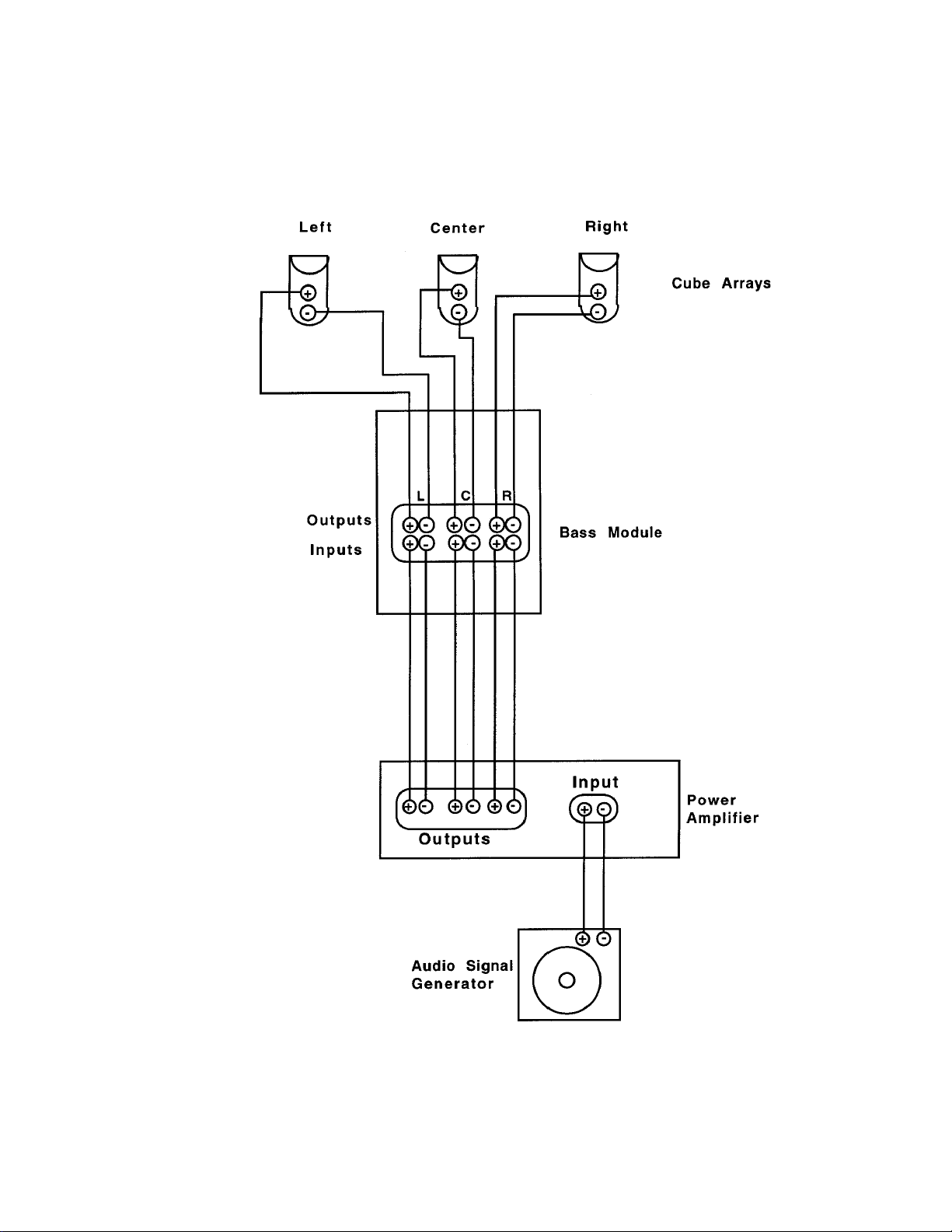
AM-7 Test Connection Diagram
FIGURE 1
2
Page 4

2. System Sweep Test
NOTE: Bass will only be heard in the left or right channels. The center channel is not
connected to the woofers.
2.1 Connect the amplifier leads to either the left, right or center channel inputs on the bass
module. Sweep the oscillator from 10 Hz to 1 kHz using a 10 Vrms signal. There should
not be any loud extraneous sounds. If there are any loud buzzes or distortion, replace the
woofer(s).
NOTE: There should not be any buzzes or rattles from within the bass module. Redress
any wire or component that buzzes.
2.2 Reduce the amplifier output to 5 Vrms and continue sweeping from 1 kHz to 15 kHz. If
any twiddler™ buzzes or sounds distorted, replace it.
2.3 Repeat this procedure for the other two channels.
NOTE: If a cube array or bass module malfunctions, check all connections and look for
faulty components on the crossover assembly. Refer to the Disassembly Procedures
section for further instructions.
3. Air Leak Test
Adjust the oscillator frequency to 45 Hz and the amplifier output to 10 Vrms. For at least 5
seconds, listen for air leaks around the terminal cap panel and the terminal cup. If there is
a "whooshing" or "sputtering" noise around the terminal cap panel or terminal cup, reposition their mounting gaskets to make an airtight seal.
4. Automatic System Protection Test
4.1 For the left and right channels, connect the amplifier leads to either the left or right
channel inputs on the bass module. Set the oscillator frequency to 90 Hz and the amplifier
output to 30 Vrms. Connect a voltmeter across the output terminals of the bass module.
Do not apply the signal for more than 60 seconds. There should be a gradual reduction in
the sound level. The bass module output voltage should decrease from approximately 8
Vrms to 4 Vrms. Repeat this test on the other channel.
NOTE: If the sound level stays the same, then polyswitches PTC2 ( left channel) or PTC1
(right channel) may be defective. If the sound level decreases sharply, then lamps DS4 and
DS5 (left channel) or DS1 and DS2 (right channel) might be defective. Refer to the
schematic diagram in Figure 2.
4.2 For the center channel, connect the amplifier leads to the center channel input on the
bass module. Set the oscillator frequency to 200 Hz and the amplifier output to 20 Vrms.
Connect a voltmeter across the output terminal of the bass module. Do not apply the signal
for more than 60 seconds. There should be a gradual reduction in the sound level. The
bass module output voltage should decrease from approximately 12 Vrms to 8 Vrms.
3
Page 5
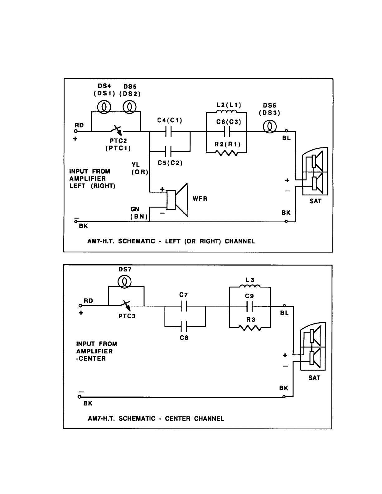
Schematic Diagram
FIGURE 2
4
Page 6

NOTE: If the sound level stays the same, then polyswitch PTC3 may be defective. If the sound
level decreases sharply, then lamp DS7 may be defective. Refer to the schematic diagram in
Figure 2.
5. Woofer Phase Test
Adjust the frequency of the oscillator to 45 Hz and the amplifier output to 10 Vrms. Disconnect either the LEFT or RIGHT input to the bass module. The sound output from the bass module should decrease.
NOTE: If the sound output increases or stays the same, the woofer could be defective or the
wiring is incorrect.
6. Twiddler Phase Test (Cube Arrays)
NOTES: Do not use Figure 1 for this procedure. The cube arrays should be removed from the
test setup.
Supply voltage should only be momentarily applied to the cube array input terminals to avoid
possible damage to the twiddlers.
Set a DC power supply to 10 volts. To ensure that each twiddler™ is connected in phase,
connect the positive supply lead to the positive (+) cube array input terminal (red) and the negative supply lead to the negative (-) cube array input terminal (black). The twiddlers in each
cube array should move outwards with the application of the supply voltage.
NOTE: If any twiddler cone deflects inward or does not move, check all connections.
7. Crossover Test
7.1 Set the amplifier output to 2 Vrms.
7.2 Adjust the oscillator frequency to 100 Hz. Measure the voltage across the input terminals
of the left, right and center cube arrays. For the left and right channels, the voltage should read
.56 ± .12 volts. For the center channel, the voltage should read .58 ± .13 volts.
7.3 Adjust the oscillator frequency to 2.5 kHz. Measure the voltage across the input terminals
of the left, right and center cube arrays. For the left and right channels, the voltage should read
± .11 volts. For the center channel, the voltage should read 1.23 ± .12 volts.
1.20
7.4 Adjust the oscillator frequency to 12 kHz. Measure the voltage across the input terminals
of the left, right and center cube arrays. For the left and right channels, the voltage should read
1.79
± .12 volts. For the center channel, the voltage should read 1.84 ± .12 volts.
5
Page 7

7.5 If the crossover circuits are working properly, all voltage readings will fall within the limits as
specified in Sections 7.2 - 7.4.
7.6 If any voltage readings fall outside these limits, the following items need to be checked:
-Check the crossover's wiring.
-Make sure all twiddlers are operating properly.
-Check protection lamps DS6 or DS3 for continuity. Check all other components on the
Crossover PCB Assembly.
NOTE: Refer to the schematic diagram shown in Figure 2.
Bass Module Test Procedures
NOTE: These procedures should be used when only the bass module is brought in to be ser-
viced. Refer to the Disassembly/Assembly Procedures section for instructions on accessing
the woofers.
1. Woofer Rub and Tick-Same as system test, Procedure 1.
2. Sweep Test- Only use 1st paragraph of system test, Procedure 2.1.
3. Air Leak Test-Same parameters as system test, Procedure 3.
4. Automatic System Protection Test-Same as system test, Procedure 4, except an 8
(rated at ≥15W) resistive load must be connected across the output terminal of the bass module.
5. Woofer Phase Test-Same as system test, Procedure 5.
6. Crossover Test-Same as system test, Procedure 7, except an 8
load must be connected across the output terminal of the bass module.
Cube Array Test Procedures
NOTE: Use these procedures only when you are testing a cube array.
1. Sweep Test
Connect an oscillator to a power amplifier. Adjust the amplifier to 5 Vrms. Connect the amplifier
leads to the cube input terminals. Sweep the oscillator from 1 kHz to 15 kHz. If the twiddler™
buzzes or sounds distorted, replace it.
Ω (rated at ≥15W) resistive
Ω
2. Twiddler Phase Test
NOTES: Refer to Figure 3 for an exploded view of the cube array (satellite).
6
Page 8

Supply voltage should only be momentarily applied to the cube array input terminals to avoid
possible damage to the twiddlers™.
Set a DC power supply to 10 volts. To ensure that each twiddler is connected in phase,
connect the positive supply lead to the positive (+) cube array input terminal (red) and the negative supply lead to the negative (-) cube array input terminal (black). The twiddlers in each
cube array should move outwards with the application of the supply voltage.
NOTE: If any twiddler cone deflects inward or does not move, check all connections.
DISASSEMBLY/ ASSEMBLY PROCEDURES
Cube Array Procedures
Note: Refer to Figure 3 for an exploded view of the cube array. The number in parentheses
corresponds to the view's callout numbers.
1. Grille Removal
Grasp the cube array with one hand. With the other hand, grasp both the top and bottom of the
grille assembly (1) ( The raised catches secure the grille assembly to the sides of the enclosure).
Squeeze in and pull the grille assembly away from the cube array.
2. Grille Replacement
Align the grille assembly (1) with the cube array. Make sure that the curved edges of the grille
assembly are oriented vertically. If you are installing the bottom grille assembly, make sure it has
®
the Bose
nameplate (2) on it. The nameplate should be positioned in the lower right hand corner
of the grille assembly. Lightly snap the grille assembly into place. The raised catches will secure
the grille to the cube array.
3. Twiddler Removal
Remove the four screws (4) holding the twiddler (3) in place. Lift the twiddler out and cut the wires
connected to the twiddler as close to its terminals as possible. Strip the wires and connect them to
the replacement twiddler.
NOTE: The positive (+) terminal of each twiddler is marked with a red dot.
4. Twiddler Replacement
4.1 If you need to replace the top twiddler (3) in the array, connect the wires as
follows:
7
Page 9

Connect the grey wire to the positive (+) twiddler™ terminal and the black
wire to the negative (-) twiddler terminal.
4.2 If you need to replace the bottom twiddler in the array, connect the wires as follows:
Connect the red wire to the positive (+) twiddler terminal and the grey wire to the negative (-)
terminal.
4.3 Lower the twiddler into the cube array enclosure. Secure the twiddler to the cube array with
four screws (4). Repeat the cube array test procedures.
Bass Module Procedures
NOTE: Refer to Figures 4 and 4A for an exploded view of the bass module. The number in
parentheses corresponds to the view's callout numbers.
5. Terminal Cap Panel Removal
Remove six screws (8) which hold the terminal cap panel (12) in place. Use a flat blade and
CAREFULLY pry the terminal cap panel away from the bass module.
NOTES: The Crossover PCB Assembly (See Figure 4) is mounted on the back of the panel. Also,
both woofers (4) can be accessed once this panel is removed.
Before re-mounting the terminal cap panel, make sure that the wires which connect the woofers
to the Crossover PCB assembly are twisted into a service loop.
6. Terminal Cap Panel Replacement
Align the terminal cap panel (12) with the bass module. Push in lightly to ensure that the terminal
cap panel is properly secured in place. Install the six screws (8) that secure the terminal cap panel
to the bass module.
7. Woofer Removal
7.1 Use Procedure 5 to remove the terminal cap panel (12).
7.2 Remove four screws (5) that secure the left (or right) woofer (4) to the bass module enclosure.
NOTES: The wires connecting the woofers to the Crossover PCB Assembly are twisted into a
service loop. Untwist these wires before attempting woofer removal. Also, these wires may be
glued to the module cabinet. Carefully trim away any residual glue before attempting removal.
Carefully lift the woofer out and cut the wires connected to the woofer terminals as close to the
terminals as possible. Strip the wires and connnect to a replacement woofer.
8
Page 10

8. Woofer Replacement
8.1 If you have replaced the left woofer (4), connect the wires as follows:
Connect the yellow wire to the positive (+) terminal and the green wire to the negative (-)
terminal.
8.2 If you have replaced the right woofer, connect the wires as follows:
Connect the orange wire to the positive (+) terminal and the brown wire to the negative (-)
terminal.
NOTES: Refer to the schematic diagram in Figure 2.
When re-positioning the woofer, make sure that the woofer gasket (6) is correctly positioned
behind the woofer to make an airtight seal. Mount the woofer to the module cabinet using four
screws (5). Repeat the bass module test procedures.
9. Crossover PCB Assembly Removal
NOTE: The Crossover PCB Assembly is located on the inside of the terminal cap panel (12). For
a detailed view of this assembly, refer to Figure 4.
Remove four screws (D) and rubber feet (not shown) that secure the assembly to the terminal cap
panel. Trim away any residual glue if necessary when removing any other components.
10. Crossover PCB Assembly Replacement
Replace four screws (D) and rubber feet that secure the PCB assembly to the terminal cap panel.
11. Terminal Cup Removal
Use Procedure 5 to remove terminal cap panel (12).
NOTE: It may be necessary to remove the terminal cap panel (12) before attempting repair. Refer
to Procedure 3 in this section.
Remove six screws (10) that secure the terminal cup (9) to the terminal cap panel (12). Lift the
terminal cup carefully away from the terminal cap panel. Remove and replace any wires as
needed. Place the terminal cup into the terminal cap panel.
12. Terminal Cup Replacement
Make sure that the terminal cup gasket (11) is aligned behind the terminal cup. Lower the terminal
cup (9) into place inside the terminal cap panel (12). And align the screw holes. Secure the
terminal cup to the panel with six screws (10).
9
Page 11

NOTES FOR FUTURE REFERENCE
10
Page 12
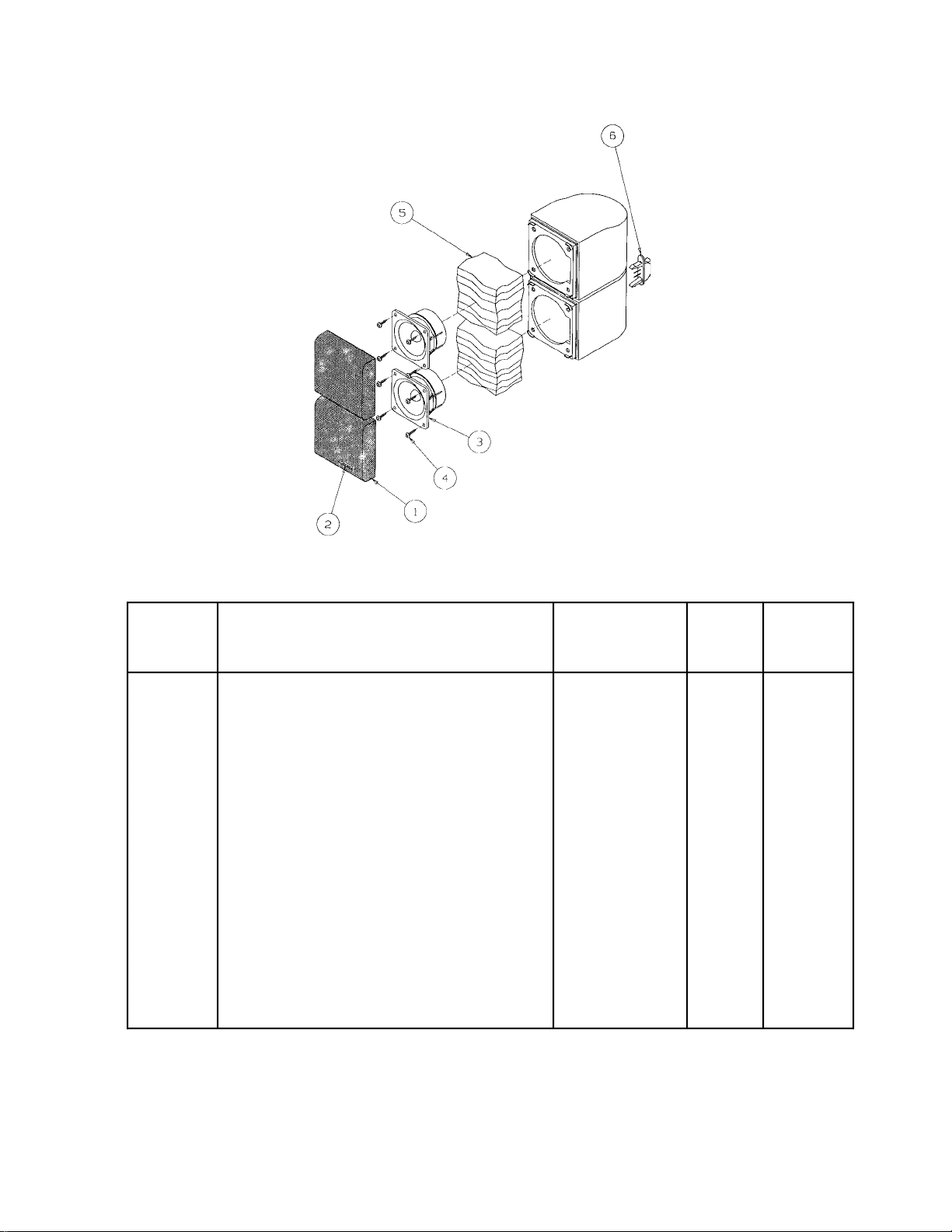
Figure 3. AM-7 Cube Array (Satellite)
AM-7 Cube Array (Satellite) Part List (Figure 3)
Item
Number
1 Grille Assembly-Black 142185-1 2
Grille Assembly-White 142185-2 2
2 Nameplate-Black 148056-1 1
Nameplate-White 148949-2 1
3 Twiddler™,Shielded,2-1/4",60 mm 184473 2
4 Screw-HIRS,8-10x5/8,PAN,XRC/SQ (Orig.) 137527-10 8
Screw-TAPP,8-11x5/8,PAN,XRC/SQ (New) 172672-10 8
5 Polyester Batting 103075 2 1
6 Terminal Strip Connector 141405 1
- Pivot,Black 141401-1 1 2
Pivot,White 141401-2 1 2
- Threaded Insert 142374 1 2
Description Part Number Qty.
Per
Cube
Array
See
Note
NOTE
1. This part is not normally stocked as a service part.
2. This part is not illustrated.
11
Page 13
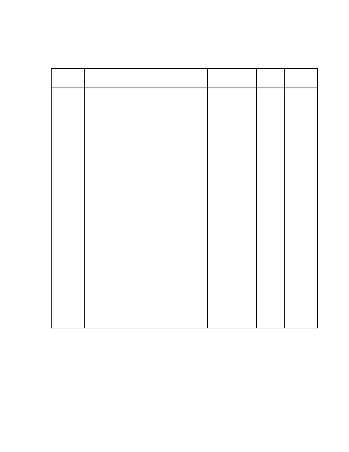
AM-7 Bass Module Part List (Figure 4)
Item
Number
Description Part Number Qty.
1 Cap-Port,Black (Original) 141384-1 1
Cap-Port,Black (New) 173310-1 1
Cap-Port,White (Original) 141384-2 1
Cap-Port,White (New) 173310-2 1
2 Port Flare-Black (Original) 141404-1 1
Port Flare-Black (New) 173312-1 1
Port Flare-White (Original) 141404-2 1
Port Flare-White (New) 173312-2 1
3 Screen-Port 145325 1
4 Woofer-5-1/4" 141393 2
5 Screw-HIRS,8-10x3/4,PAN,XRC/SQ (Orig.) 137527-12 8
Screw-TAPP,8-10x3/4,PAN,XRC/SQ (New) 172672-12 8
6 Woofer Gasket (Original) 142708-08 2
Woofer Gasket (New) 104794-08 2
7 Foam Tape (Original) 103068 N/A
Foam Tape (New) 177321 N/A
Per
Module
See
Note
8 Screw-8-10x1.5,Comb Phil/SQ BH 143322-24 6
9 Terminal Cup 147317 1
10 Screw-6-10x1/2,PAN,XRC/SQ (Original) 124773-10 6
Screw-6-13x5/8,PAN,XRC/SQ (New) 172783-10 6
11 Gasket-Terminal Cup 147450 1
12 Panel-Terminal Cap,Black 147434-1 1 1
Panel-Terminal Cap,White (Original) 147434-2 1 1
Panel-Terminal Cap, Arc.White (New) 147434-9 1 1
NOTE
1. This part is not normally stocked as a service part.
12
Page 14
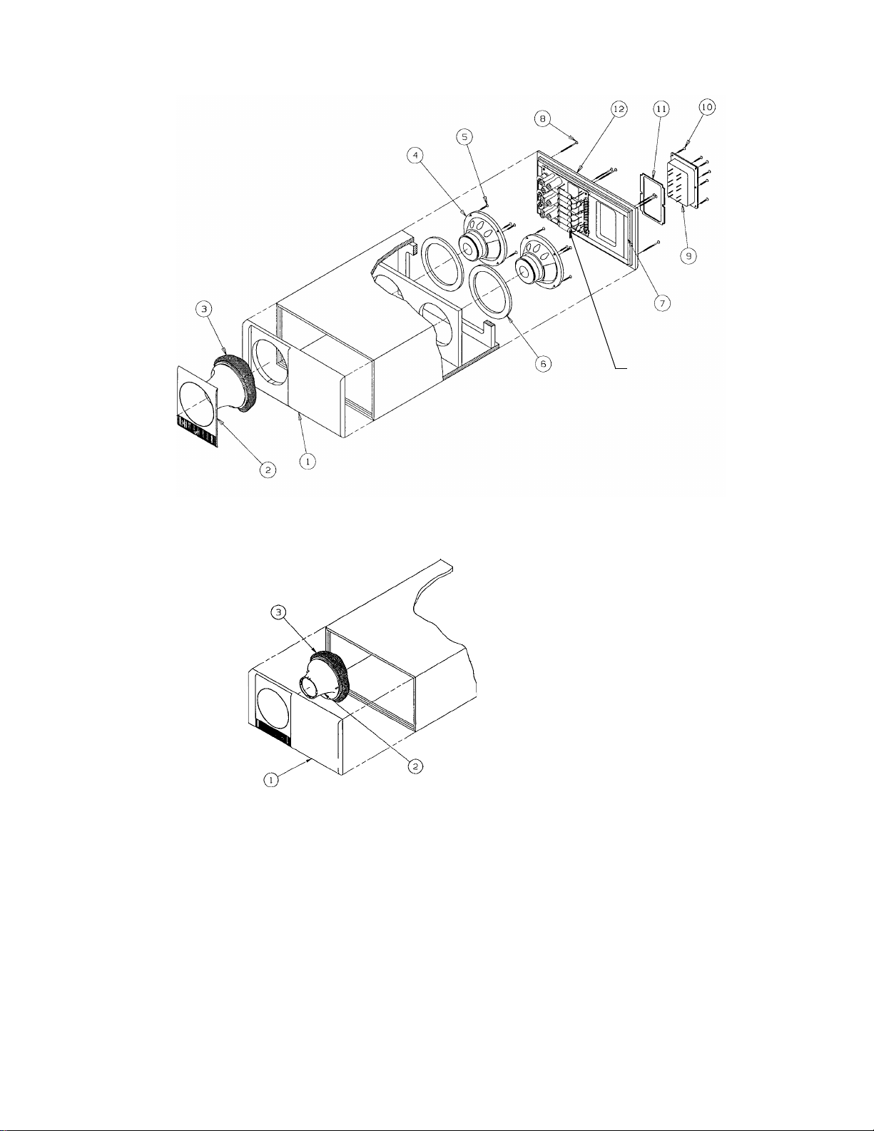
Figure 4. AM-7 Bass Module (Original Design)
Crossover PCB
Assembly
See Figure 5
Figure 4A. AM-7 Bass Module (New Design)
13
Page 15
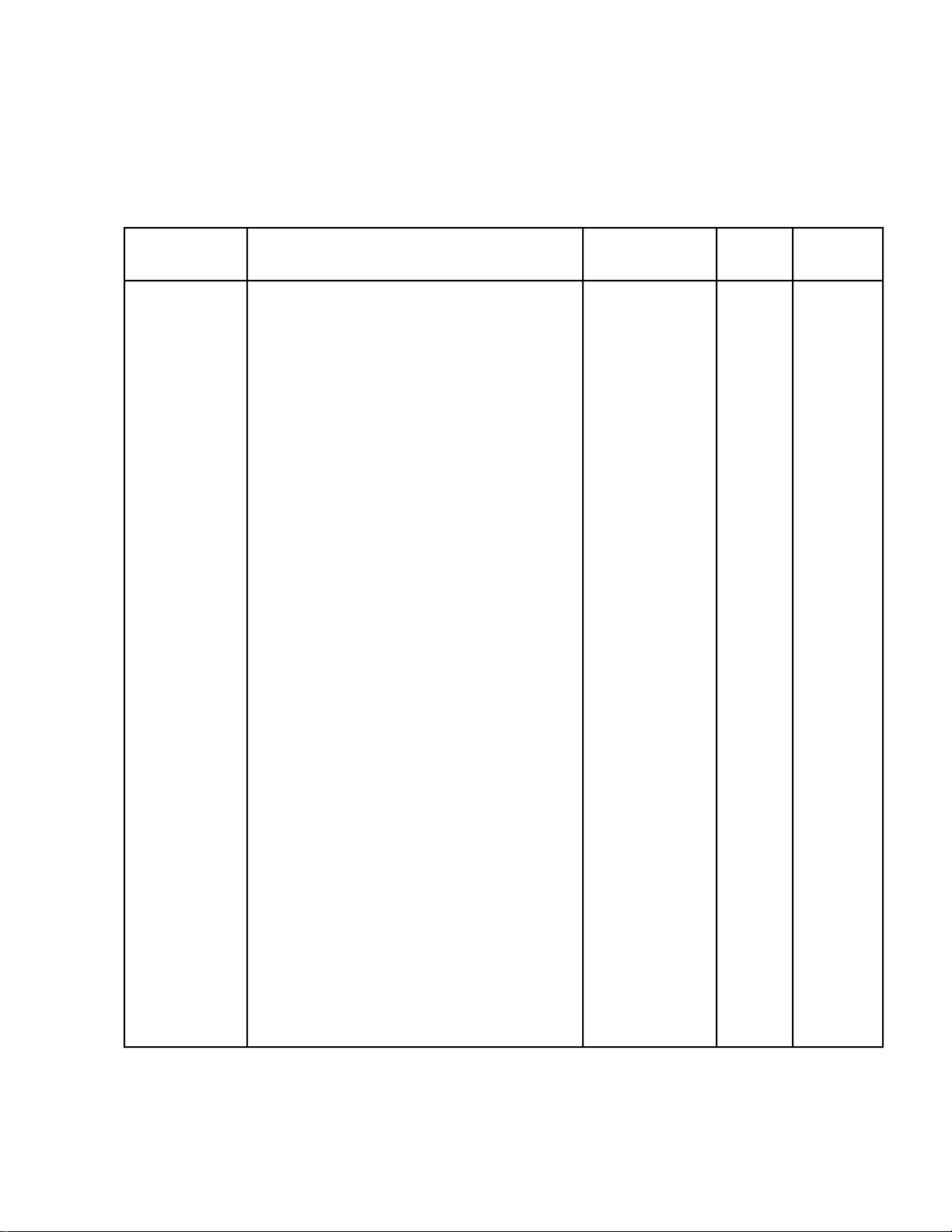
AM-7 Crossover Assembly Part List (Figure 5)
Symbol
or Item
Number
Description Part Number Qty.
Per
Assy.
C1,C2, Capacitor-EL,50V,33µF 131974 4
C4,C5
C7,C8 Capacitor-EL,50V,47µF 136548 2
C3,C6, Capacitor-EL,Bi-polar,RDL,50V,15µF 132079 3
C9
DS1,DS2 Lamp 117805 6
DS3,DS4
DS5,DS6
DS7 Lamp-Overload Protection 141989 1
L1,L2,L3 Inductor,300µH 131973 3
PTC1,PTC2 Polyswitch (Original) 121247 2
Polyswitch (New) 175233-1 2
PTC3 Polyswitch,0.5A,60V 147185 1
R1,R2, Resistor,WW,5W,5.1Ω 132105-5R1 3
R3
See
Note
Foil Tape W/Liner (Not Shown) 134636 N/A 1
A Screw-Machine,4-40x1,PAN,XREC 103146-16 3
B Nut-HEX,#4-40,Brass 103234-440 3
C Washer-Flat,#5,Brass or 108258-05 3
Washer-Flat,#4,Brass 108258-04 3
D Screw-HIRS,8-10x5/8,PAN,XRC/SQ (Orig.) 137527-10 4
Screw-HIRS,8-11x5/8,PAN,XRC/SQ (New) 172672-10 4
E Foot-Crossover (Not Shown) (Original) 125058-1 4
Foot-Crossover (Not Shown) (New) 174402-1 4
F Pin,.045,Square (Original) 129000 4
Pin,.045, Square (New) 129000-5234 4
NOTE
1. This part is not normally stocked as a service part.
14
Page 16
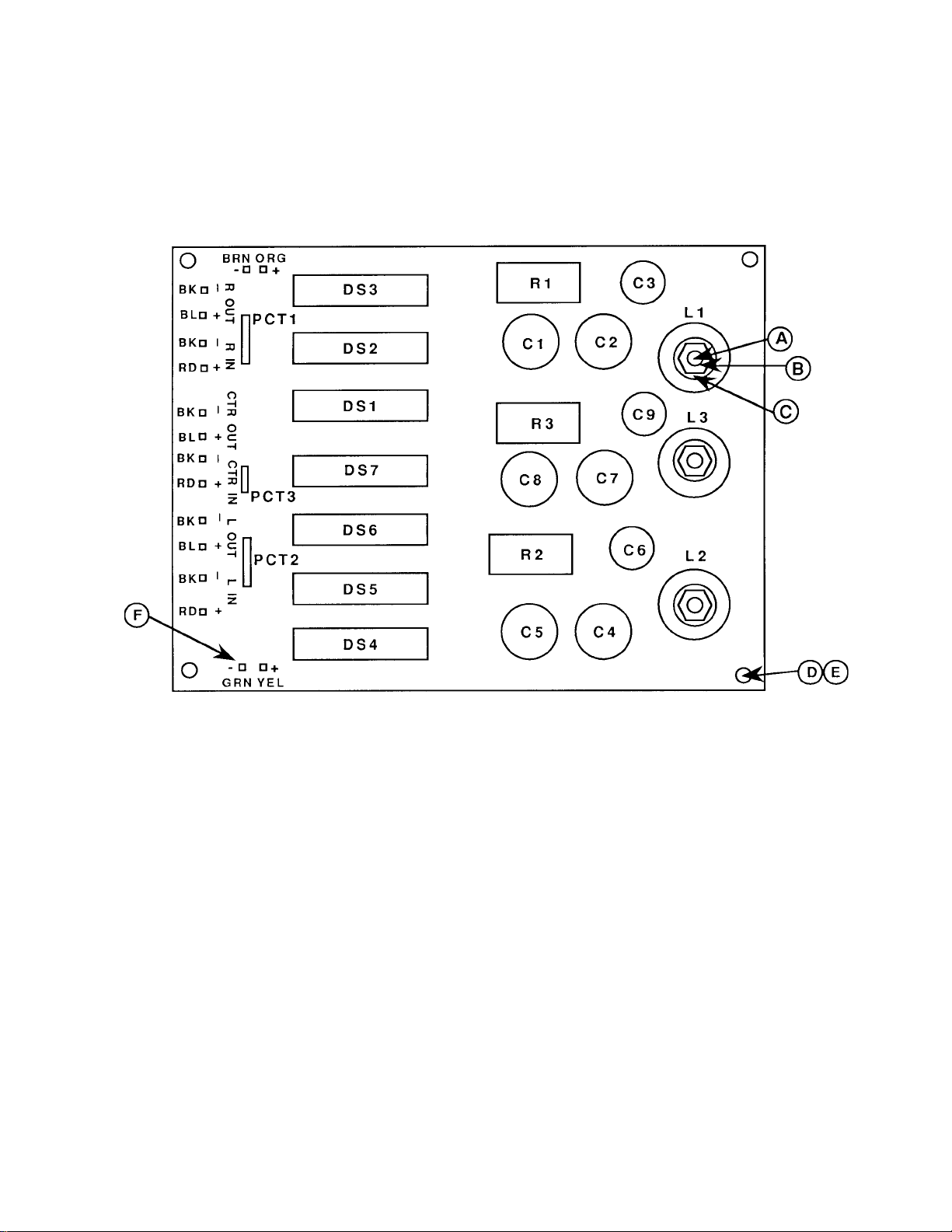
Figure 5. AM-7 Crossover PCB Assembly
15
Page 17
AM-7 Packaging Part List (Figure 6)
Item
Number
Description Part Number Qty. See Note
1 Literature Kit 147301 1
consists of:
A Foot 142839 4
B Owner's Manual 147189 1
C Polybag 103351 1
D Information Card,Warranty, U.S. 181357 1
E All Products Brochure 141478 1
F Warranty Service List 122766 1
G Information Card,Warranty,Multi-Lan. 181460 1
H Sht, DEC of Conformity 184062 1
2 Packing Tray,D/C,AM-7 148363 1
3 Cable-Interconnect,Black,20' 130915 6
Cable-Interconnect,White,20' 140236 6
4 Packing,Corner,Post,Bass Insert 148364 2
5 Polybag (Bass Module) 114522 1
6 Packing,Corner,Post,Bass Insert 148044 2
7 Carton,RSC,AM-7HT 149172-02 1
8 Polybag (Satellite Parts) 144677 3
9 Carton,CHP,Sat Pr. Assy, AM-5II 148365 3
16
Page 18
(2)
4
(6)
3
2
(2)
6
(4)
E
DC B A
OR
1
8
7
5
H
GF
(3)
(3)
9
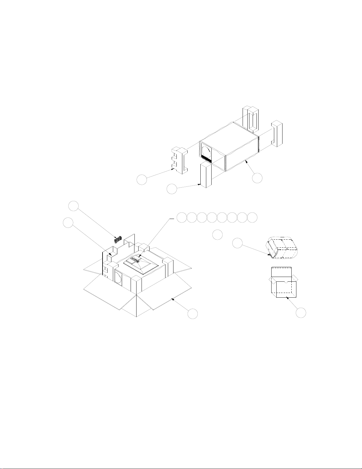
Figure 6. AM-7 Packaging
17
Page 19

NOTES FOR FUTURE REFERENCE
18
Page 20

SPECIFICATIONS AND FEATURES SUBJECT TO CHANGE WITHOUT NOTICE
Bose Corporation
The Mountain
Framingham, Massachusetts USA 01701
P/N 149359 02/96: Rev.1
FOR TECHNICAL ASSISTANCE OR PART ORDERS, CALL 1-800-367-4008
 Loading...