

Page 1
®
LIFESTYLE
HOME ENTERTAINMENT SYSTEMS
WITH THE VS-2 VIDEO ENHANCER
Owner’s Guide
Guía de usario
Notice d’utilisation
DVD
Page 2
SAFETY INFORMATION
EnglishTAB 6TAB 8 TAB 7 TAB 3TAB 5 TAB 2TAB 4
Please read this guide
Please take the time to follow the instructions in this guide
carefully. They will help you set up and use your system
properly so you can enjoy all of the advanced features. Please
save this guide for future reference.
WARNINGS:
The lightning flash with arrowhead symbol within an
equilateral triangle alerts the user to the presence of
uninsulated, dangerous voltage within the system
enclosure that may be of sufficient magnitude to constitute a
risk of electric shock.
The exclamation point within an equilateral triangle alerts
the user to the presence of important operating and
maintenance instructions in this guide.
• To reduce the risk of fire or electrical shock, do not expose
the product to rain or moisture.
• Do not expose this apparatus to dripping or splashing, and
do not place objects filled with liquids, such as vases, on or
near the apparatus. As with any electronic products, use
care not to spill liquids into any part of the system. Liquids
can cause a failure and/or a fire hazard.
• Do not place any naked flame sources, such as lighted
candles, on or near the apparatus.
CAUTIONS:
• Use of controls or adjustments or performance of procedures other than those specified herein may result in
hazardous radiation exposure. The compact disc player
should not be adjusted or repaired by anyone except
properly qualified service personnel.
• Make no modifications to the system or accessories.
Unauthorized alterations may compromise safety, regulatory compliance, and system performance, and may void
the warranty.
Additional safety information
See the additional instructions on the
Information
sheet enclosed in the shipping carton.
Important Safety
Note:
• Where the mains plug or appliance coupler is used as the
disconnect device, such disconnect device shall remain
readily operable.
• The product must be used indoors. It is neither designed
nor tested for use outdoors, in recreation vehicles, or on
boats.
• This product is intended to be used only with the power
supply provided.
ii
Page 3
TAB 5TAB 4TAB 6TAB 8TAB 7English TAB 3TAB 2
Class 1 laser product
This CD/DVD player is classified as a
CLASS 1 LASER PRODUCT according
to EN 60825-1:1994+A1+A2,
IEC60825-1:1993+A1+A2.
CLASS 1 LASER PRODUCT
KLASSE 1 LASER PRODUKT
LUOKAN 1 LASER LAITE
KLASS 1 LASER APPARAT
Class B emissions
• This Class B digital apparatus meets all requirements of the
Canadian Interference-Causing Equipment Regulations
(Canada only).
• If applicable, the radio communication device incorporated
into this apparatus meets all requirements of the
Industry Canada standard RSS-310 (Canada only).
This product conforms to the EMC Directive 2004/108/EC and
to the Low Voltage Directive 2006/95/EC. The remote control
conforms to the RTTE Directive 99/5/EC. The complete
Declaration of Conformity can be found at:
www.
Bose
.com/static/compliance/index.html.
Batteries
Please dispose of used batteries properly, following any local
regulations. Do not incinerate.
Important product registration
Registering your product entitles you to receive free system
upgrades to keep your product performing optimally. It also
allows us to send you information about new products and
special offers from Bose.
Please follow the instructions on your Product Registration
card to register by mail, on the Internet, or by phone. Failure
to register will not affect your limited warranty rights.
For Your Records
Bose recommends that you record your system model
information here and the serial numbers both here and on
your Product Registration Card.
Serial numbers are located on the bottom of the media
center and the VS-2, and on the connection panel of the
Acoustimass
System model name and number (on the carton):
LIFESTYLE® ______________________________ Series #______
Serial numbers:
Media center Ser Num: ____________________________________
VS-2 bar code: ___________________________________________
Acoustimass® module SN: _________________________________
Dealer name: ____________________ Dealer phone: _________
Purchase date: ___________________________________________
It may be helpful to keep your sales receipt and a copy of your
Product Registration card together with this guide.
®
module.
iii
Page 4
CONTENTS
EnglishTAB 6TAB 8 TAB 7 TAB 3TAB 5 TAB 2TAB 4
INTRODUCTION 2
Welcome . . . . . . . . . . . . . . . . . . . . . . . . . . . . . . . 2
Simplifying your setup . . . . . . . . . . . . . . . . . . . . . 3
Unpacking the carton . . . . . . . . . . . . . . . . . . . . . . 3
SYSTEM SETUP 6
1 Choosing locations for the system . . . . . . . . . . . . 6
Arranging the system around your room . . . . . . . 7
Positioning the front and center speakers . . . . 7
Positioning the rear speakers . . . . . . . . . . . . . . 8
Arranging the media center and VS-2 . . . . . . . 9
Positioning the Acoustimass
Looking over your finished placement . . . . . . . 12
®
module . . . . . . . 10
COMPLETE SYSTEM CONNECTIONS 13
2 Connecting speaker cables . . . . . . . . . . . . . . . . . 13
Connecting all of the speakers . . . . . . . . . . . . . . 14
3 Connecting the module . . . . . . . . . . . . . . . . . . . . 16
4 Connecting the media center . . . . . . . . . . . . . . . . 19
5 Disconnecting your devices from the TV . . . . . . . 25
6 Connecting your TV . . . . . . . . . . . . . . . . . . . . . . . 26
If an HDMI connection is not possible . . . . . . . 28
7 Connecting another device
(cable or satellite box, VCR, or DVR) . . . . . . . . . . 29
Connecting the video from your cable
or satellite box first . . . . . . . . . . . . . . . . . . . . . . . 30
Adding audio from your cable or satellite box . 32
Including a digital audio connection . . . . . . . . 33
Adding more devices . . . . . . . . . . . . . . . . . . . . 34
8 Attaching the IR emitter and TV sensor . . . . . . . 35
9 Connecting the AM and FM antennas . . . . . . . . 37
10 Connecting the system to power . . . . . . . . . . . . 39
11 Setting the remote to control your TV
and other devices . . . . . . . . . . . . . . . . . . . . . . . . 40
Inserting the remote batteries . . . . . . . . . . . . . . . 40
Making it a universal remote . . . . . . . . . . . . . . . . 41
Setting the remote for TV control . . . . . . . . . . . 41
Setting the remote for cable or satellite . . . . . . 44
Setting the remote for another device . . . . . . . 46
12 Tailoring the sound to your room . . . . . . . . . . . . 47
Getting the sound you want. . . . . . . . . . . . . . . . . 47
Beginning the process . . . . . . . . . . . . . . . . . . . 48
Finishing the process . . . . . . . . . . . . . . . . . . . . 49
Storing any parts you do not need . . . . . . . . . . . 49
USING AND ENJOYING YOUR SYSTEM 50
Introducing the basics . . . . . . . . . . . . . . . . . . . . . .50
Turning on the system . . . . . . . . . . . . . . . . . . . . 50
Turning on your TV . . . . . . . . . . . . . . . . . . . . . . . 50
iv
Page 5

TAB 5TAB 4TAB 6TAB 8TAB 7English TAB 3TAB 2
CONTENTS
Getting the sound for your video . . . . . . . . . . . . . 50
Getting the video to appear . . . . . . . . . . . . . . . . . 50
Using the system controls . . . . . . . . . . . . . . . . . . . . 51
An introductory overview . . . . . . . . . . . . . . . . . 51
The remote control . . . . . . . . . . . . . . . . . . . . . . 51
The media center . . . . . . . . . . . . . . . . . . . . . . . 52
USING THE VARIOUS SOURCES 53
Playing a disc . . . . . . . . . . . . . . . . . . . . . . . . . . . . 53
Cleaning discs . . . . . . . . . . . . . . . . . . . . . . . . . 53
To control play . . . . . . . . . . . . . . . . . . . . . . . . . 54
Discs that are system compatible . . . . . . . . . . 54
Using the radio . . . . . . . . . . . . . . . . . . . . . . . . . . 55
To change stations . . . . . . . . . . . . . . . . . . . . . . 55
Using radio station presets . . . . . . . . . . . . . . . . 55
Using your TV, cable, satellite, DVR, or VCR . . . . 56
To control play . . . . . . . . . . . . . . . . . . . . . . . . . 56
MAKING LONG- OR SHORT-TERM
ADJUSTMENTS 57
Changing system and source settings . . . . . . . . 57
Long-term system adjustments . . . . . . . . . . . . 57
Short-term source settings . . . . . . . . . . . . . . . . 57
Changing the on-screen language . . . . . . . . . . . . 58
Other system options . . . . . . . . . . . . . . . . . . . . 59
Adjusting the audio timing . . . . . . . . . . . . . . . . . . 61
Settings options . . . . . . . . . . . . . . . . . . . . . . . . . . 62
REFERENCE 64
Connections: For TVs requiring SCART
(in Europe, only) . . . . . . . . . . . . . . . . . . . . . . . . . . . . 64
More about DVD play . . . . . . . . . . . . . . . . . . . . . . 67
To repeat a segment of the DVD . . . . . . . . . . . . 67
Setting DVD Parental Control . . . . . . . . . . . . . . 67
Maintaining the system . . . . . . . . . . . . . . . . . . . . . 69
Protecting and keeping it clean . . . . . . . . . . . . . 69
Checking your remote control response . . . . . . 69
Replacing the remote control batteries . . . . . . . 70
Changing remote control switch settings . . . . . 71
Setting up other rooms with sound . . . . . . . . . . . 73
®
link-compatible products
Bose
make it easy . . . . . . . . . . . . . . . . . . . . . . . . . . . . 73
Troubleshooting . . . . . . . . . . . . . . . . . . . . . . . . . . 74
Contacting Bose . . . . . . . . . . . . . . . . . . . . . . . . . . 79
Limited Warranty . . . . . . . . . . . . . . . . . . . . . . . . . 79
Technical information . . . . . . . . . . . . . . . . . . . . . . 80
END USER LICENSE AGREEMENT . . . . . . . . . . . 82
v
Page 6

INTRODUCTION
EnglishTAB 6TAB 8 TAB 7 TAB 3TAB 5 TAB 2TAB 4
Welcome
Thank you for purchasing this Bose® LIFESTYLE® DVD
home entertainment system. This elegant and easy-touse system delivers superior performance for both
music and video program content.
With its many innovations, this system includes the
VS-2 video enhancer that provides HDMI
connectivity and convenient video switching.
TM
video
Among the advanced features you can discover:
• HDMI video inputs and output to your TV
• Automatic video switching provided by the VS-2
video enhancer
• Proprietary ADAPTiQ
tailors system audio for optimal performance in the
room where your system is located
• Expansion capabilities that let you add to your
system in up to 13 other rooms
®
audio calibration system that
2
Page 7
TAB 5TAB 4TAB 6TAB 8TAB 7English TAB 3TAB 2
INTRODUCTION
Simplifying your setup
The detailed instructions that follow will guide you to:
• Set up the system where you want it.
• Connect all of its part.
• Make the right choice for connecting to your TV.
• Add external audio or video devices to the system.
• Custom tailor the sound to the profile of your room.
• Turn on and try out the system features and controls.
Unpacking the carton
Carefully unpack your system and save all of the
packing materials for safely shipping or transporting
the product.
If any part appears damaged, do not attempt to use it.
Notify Bose or your authorized Bose
immediately.
For Bose
sheet included in the carton.
Note: While unpacking, you can locate the system serial
numbers easily. Look on the bottom of the media center
and the VS-2 and near the connection panel on the
Acoustimass
For future reference, we suggest that you record those
numbers in the space provided at the front of this book,
on page iii.
®
contact information, refer to the address
®
module.
®
dealer
3
Page 8
INTRODUCTION
LIFESTYLE® 35/48 OR
(4) (1)
LIFESTYLE® 28/38
(4) (1)
OR
LIFESTYLE®
38/48 28/35
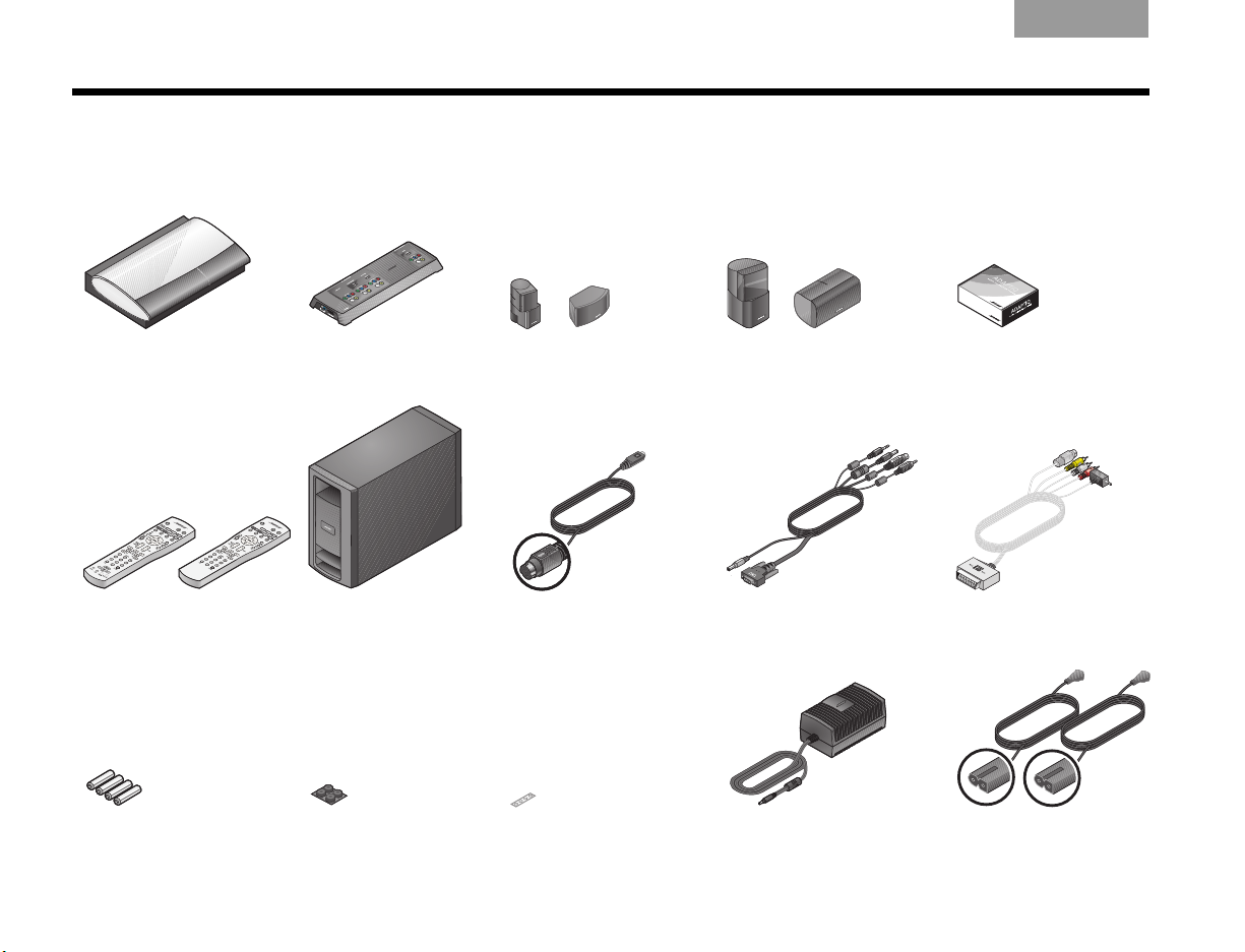
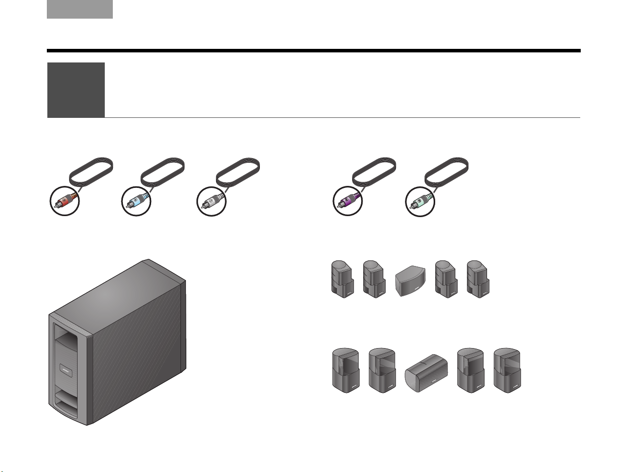
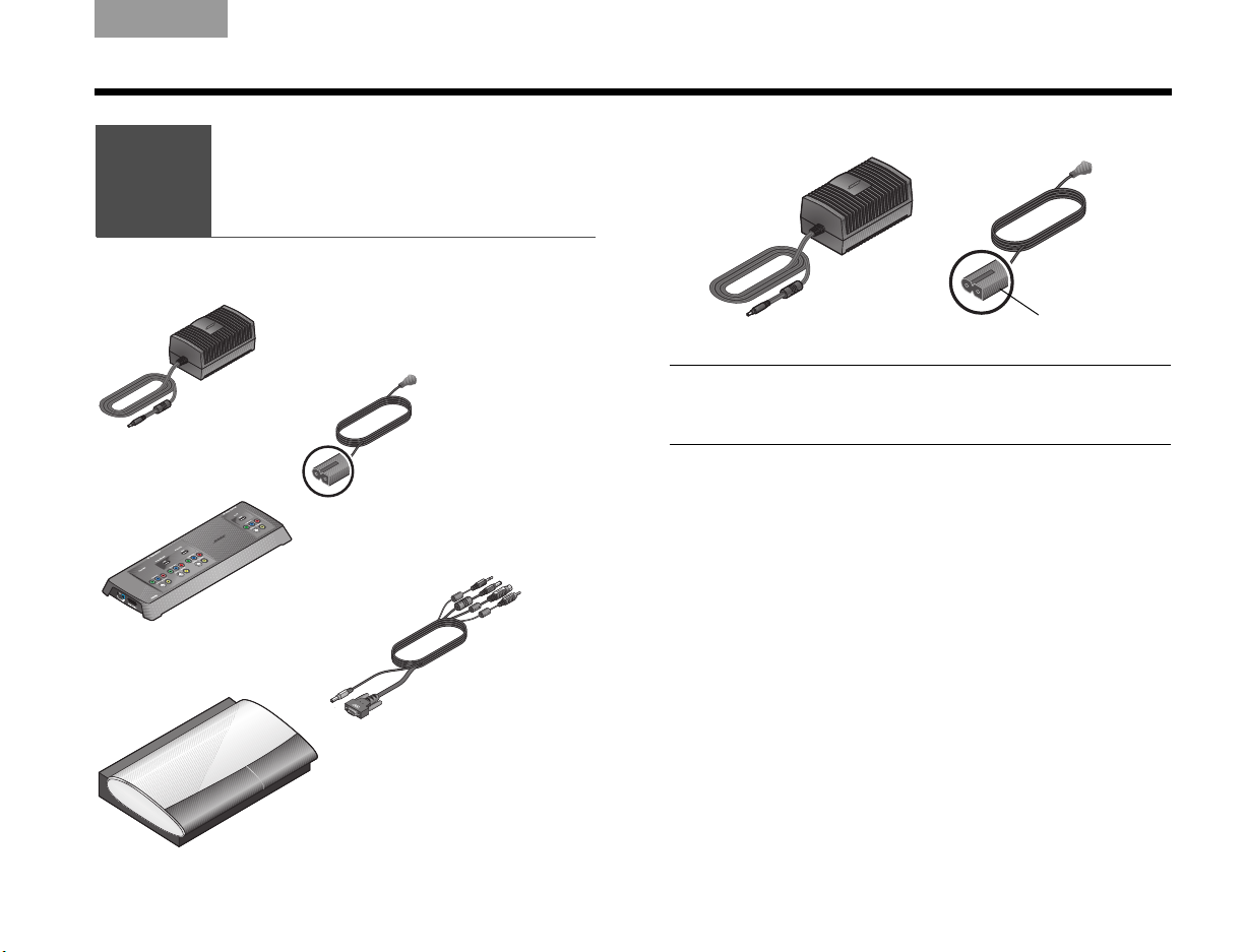
Included parts
As you unpack the carton, you can check to be sure it includes these parts.
EnglishTAB 6TAB 8 TAB 7 TAB 3TAB 5 TAB 2TAB 4
❏ Media center ❏ VS-2
❏ Remote control ❏ Acoustimass
❏ Remote control
batteries
4
video enhancer
module
❏ Acoustimass®
module rubber feet
❏ Jewel Cube® .
speakers
®
❏ Audio input cable ❏ VS-2 cable ❏ SCART adapter
❏ Direct/Reflecting
speakers
®
❏ ADAPTiQ
calibration system
®
audio
(for Europe only)
❏ Speaker
❏ Power supply ❏ 2 AC power cords
rubber feet
Page 9
TAB 5TAB 4TAB 6TAB 8TAB 7English TAB 3TAB 2
Light Blue
Brown
White
Purple
Light Green
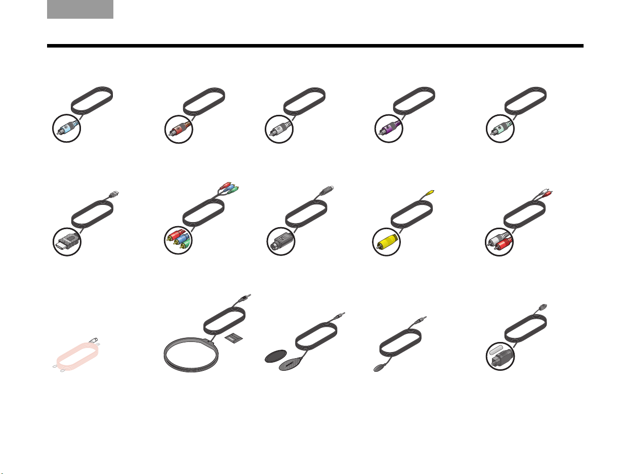
INTRODUCTION
❏ Right
speaker cable
❏ HDMI™ cable ❏ Component video
❏ FM antenna ❏ AM antenna ❏ TV on/off sensor ❏ IR emitter cable ❏ Optical audio
❏ Center
speaker cable
cable
❏ Left
speaker cable
❏ S-Video cable ❏ Composite cable ❏ Stereo audio
❏ Right Rear
speaker cable
❏ Left Rear
speaker cable
cable
cable
5
Page 10
SYSTEM SETUP
Choosing locations
for the system
1
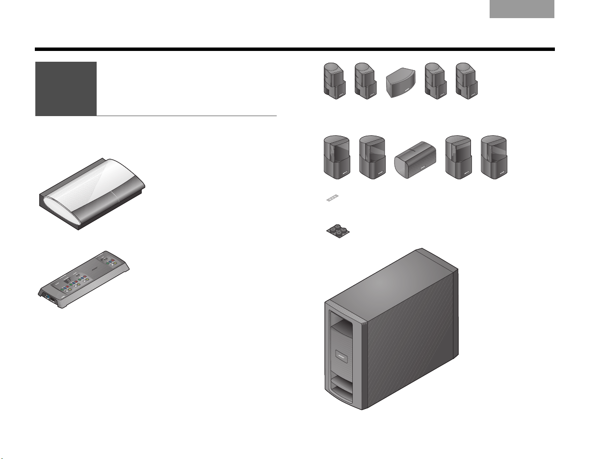
What you need to use:
Media center
VS-2 video
enhancer
5 Jewel Cube® speakers
OR
5 Direct/Reflecting
®
speakers
Acoustimass
module
Center speaker
rubber feet
Acoustimass
®
module
rubber feet
EnglishTAB 6TAB 8 TAB 7 TAB 3TAB 5 TAB 2TAB 4
6
Page 11
TAB 5TAB 4TAB 6TAB 8TAB 7English TAB 3TAB 2
F
ro
n
t
sp
e
a
k
e
r
s
L
e
f
t
C
e
n
te
r
R
i
g
h
t
SYSTEM SETUP
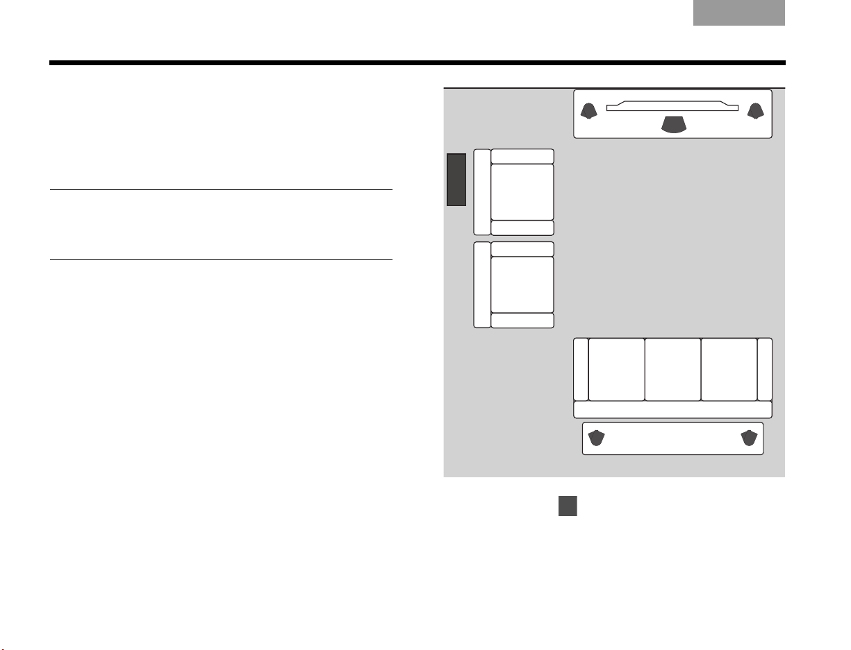
Arranging the system around your room
For convenience in setting up your speakers, Bose
offers floor stands, table stands, and wall brackets. For
the rear speakers, we also offer a wireless connect kit.
To get further information or to order accessories, call
your Bose dealer. Or to contact Bose directly, refer to
the address list provided in the carton.
The images that follow show the speakers placed
without the use of brackets or stands.
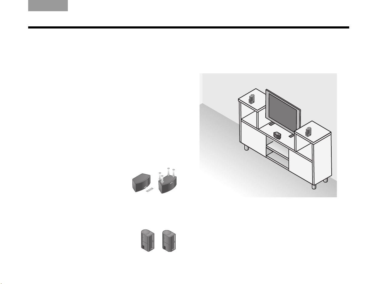
Positioning the front and center speakers
These three front speakers center the dialogue and
create a broad stage of sound that matches what you
see on screen.
1. Attach the provided rubber feet
2. Place the center speaker in a horizontal position on
3. Place one vertical speaker to the
to the center speaker if it sits on
a surface like a shelf, a table, or
the TV.
a stable and level surface.
It can go above or below your TV.
left and one to the right of the TV.
Keep these left and right speakers within 3 ft (1 m)
of the TV screen, so the sound and picture work
together.
At the front of your room:
Make sure:
• Any speakers placed on a shelf are near the front
edge of the shelf.
Placing them farther back can change the tonal
quality of the sound.
7
Page 12
SYSTEM SETUP
R
e
a
r
s
p
e
a
k
e
r
s
L
e
f
t
R
i
g
h
t
EnglishTAB 6TAB 8 TAB 7 TAB 3TAB 5 TAB 2TAB 4
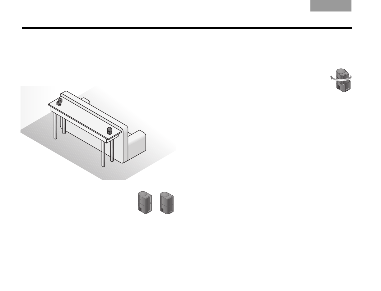
Positioning the rear speakers
These two speakers perform at the back of the room to
provide lifelike surround sound when it is needed for
special effects.
Toward the rear of your room:
1. Place one speaker to the left and
the other to the right of the viewers
and facing the front of the room.
Keep these two speakers as far
from the viewers as is practical.
Make sure:
• To aim the speakers away from the listeners so the
source of the sound is not obvious.
• To rotate the top of all four of the vertical
speakers that are at the front and rear of
the room.
This helps create the lifelike sound your
system is designed to provide.
Note:
During placement, you may discover that you need
additional cables, which are available from your local
Bose dealer.
If you prefer to contact Bose directly, refer to the address
list provided in the carton, or visit Bose on the web at:
www.Bose.com.
2. Position each speaker at ear height (when seated)
or higher, if possible.
8
Page 13
TAB 5TAB 4TAB 6TAB 8TAB 7English TAB 3TAB 2
M
e
d
i
a
c
e
n
t
e
r
Space for
other devices
V
S-
2
SYSTEM SETUP
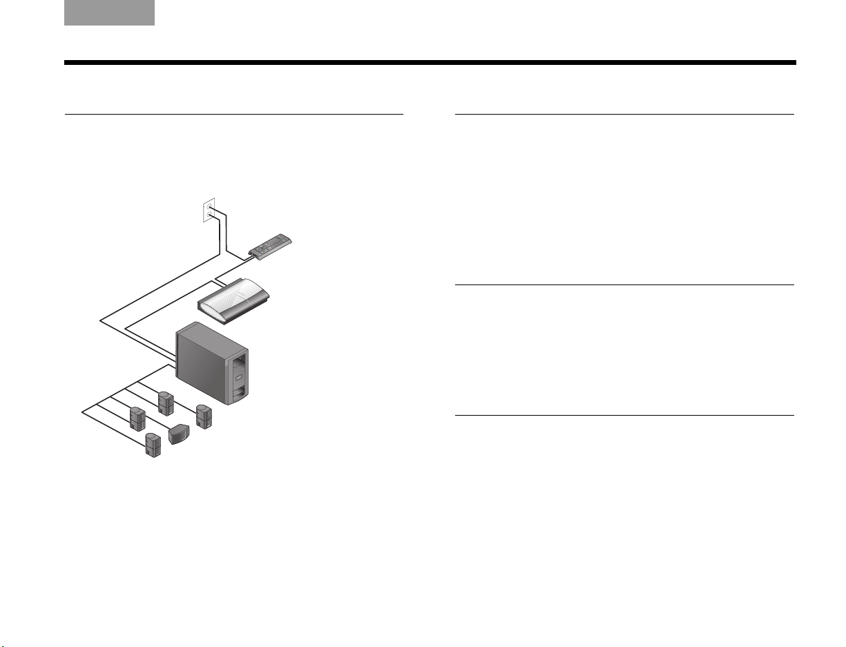
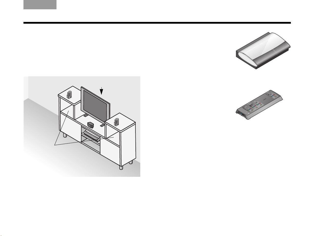
Arranging the media center and VS-2
Keep both the media center and VS-2 video enhancer
positioned for easy access in making connections.
When the connections are complete, you can move the
two units into final position.
With the VS-2 close to (behind) the media center:
1. Place the media center
on a flat, stable surface.
Allow space to lift the
front cover and open the
disc tray on the media
center. Also avoid
obstructions that block
your view of the front
display window.
2. Position the VS-2 behind
the media center – on
the floor, on an entertainment center shelf, or
mounted to the wall.
Make sure:
• The VS-2 and the media center are within 6 ft (1.8 m)
of each other.
• An AC power (mains) outlet is within 10 ft (3 m) of the
VS-2.
• The video cables from other devices (cable/satellite
box, DVR, VCR, or other) can reach the VS-2.
• The audio cables from these devices can reach the
media center.
9
Page 14
SYSTEM SETUP
Acoustimass
module
EnglishTAB 6TAB 8 TAB 7 TAB 3TAB 5 TAB 2TAB 4
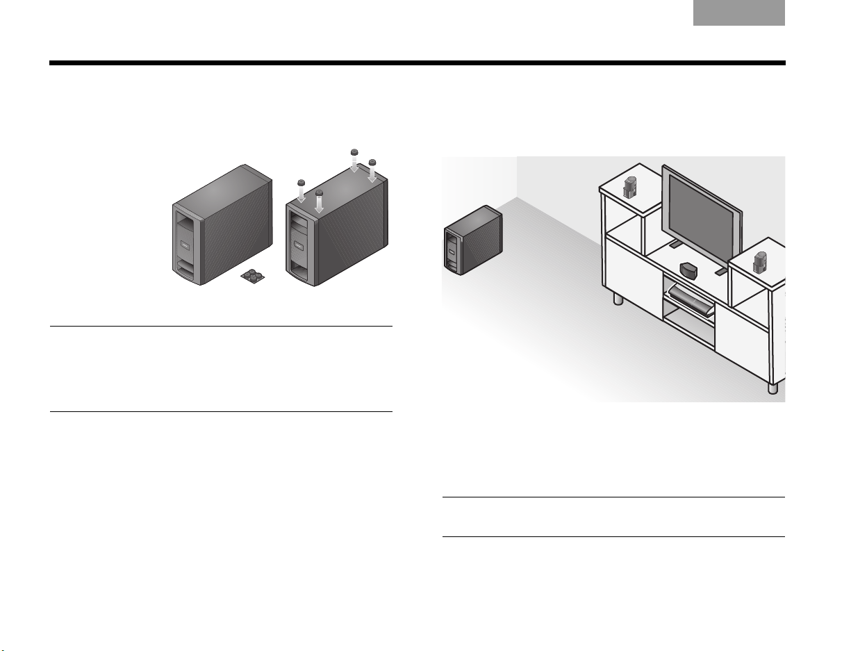
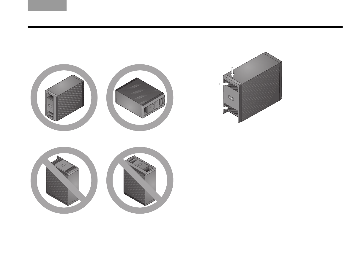
Positioning the Acoustimass® module
This speaker produces the deep bass sounds that
make you feel – not just hear – the on-screen action.
1. Attach the
Note: You may want to keep the module temporarily
standing on a side or upside down so you can make the
connections easily. When the connections are completed,
place the module in the location and position you have
chosen.
2. Place the module at the same end of the room as
four selfadhesive
rubber feet
to the bottom
surface of the
module.
These provide stability
and protect both the floor and the module.
your TV and the three front speakers.
You can place one side against a wall or position
the front facing into the room, NOT into a wall or
corner.
Avoid placing the module midway between two
walls or between the floor and ceiling.
Keep the module at least 18 in (.5 m) from your TV
to prevent interference and several feet (.8 m) from
audio or video tapes to prevent magnetic damage
to them.
3. Set the module on a side or the bottom surface,
but NOT standing on either end.
You can slide it behind a sofa or chair, under a
table, or behind drapes.
CAUTION: Do not block the ventilation openings on the
front and rear of the module.
10
Page 15
TAB 5TAB 4TAB 6TAB 8TAB 7English TAB 3TAB 2
Rear of the
Acoustimass®
module
SYSTEM SETUP
Ways to prevent ventilation blocking:
• Stand the module upright (BEST) or on a side
(ALTERNATE).
• DO NOT stand the module on either end.
• Place the module where the rear vents are open to air
flow.
Make sure:
• The module is NOT in an enclosure, on a bed or sofa,
or on a surface that can block the ventilation
openings.
• All speaker cables and the audio input cable from the
module can reach the rear of the module.
• An AC power (mains) outlet is within 10 ft (3 m) of the
module.
11
Page 16
SYSTEM SETUP
Left Center Right
Left rear Right rear
Acoustimass
®
module
TV
2
Looking over your finished placement
1. Check the overall arrangement of your system
components.
The speaker positions around the room should
follow a pattern similar to the one shown here.
Note: If you are using accessory stands or brackets with
the speakers, now is the time to follow the assembly
instructions for setting them up. The instructions include
how to wire and attach the speakers to your accessory.
EnglishTAB 6TAB 8 TAB 7 TAB 3TAB 5 TAB 2TAB 4
12
2. Continue with on the next page to begin
connecting the system.
Page 17
Connecting speaker cables
2
What you need to use:
Front speaker cables
TAB 5TAB 4TAB 6TAB 8TAB 7English TAB 3TAB 2
COMPLETE SYSTEM CONNECTIONS
e
R
a
e
s
p
r
r
c
e
k
a
s
e
a
l
b
Brown
Light blue
White
Acoustimass
module
Purple
®
Jewel Cube® speakers
Direct Reflecting
OR
Light green
®
speakers
13
Page 18
COMPLETE SYSTEM CONNECTIONS
White to L
Brown to C
Light blue to R
Purple to RR
Left
speaker
(L)
Right
speaker
(R)
Center speaker
(C)
Right
rear
speaker
(RR)
Left
rear
speaker
(LR)
Light green to LR
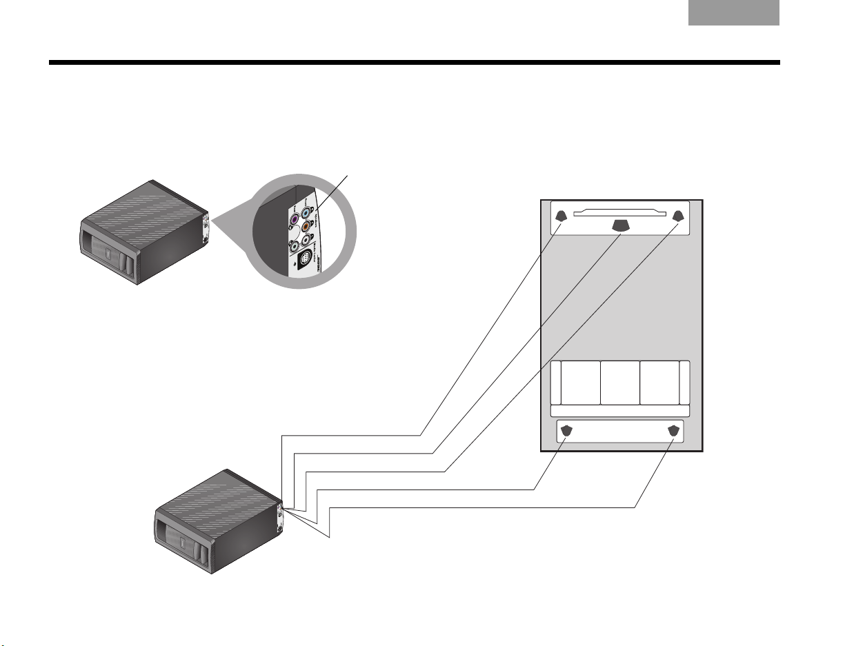
Connecting all of the speakers
1. Locate the connection panel on the lower rear of
the Acoustimass
®
module.
2. Match the color on each connector to the speaker
cable plug of the same color and insert the plug
into the matching connector.
3. Notice the letters that identify the position of the
speakers in the room view on the right.
Colored
connectors
4. Route each cable from the Acoustimass module to
the proper speaker as shown.
Use the color on the plug that is inserted into the
module as your guide.
EnglishTAB 6TAB 8 TAB 7 TAB 3TAB 5 TAB 2TAB 4
14
Page 19
TAB 5TAB 4TAB 6TAB 8TAB 7English TAB 3TAB 2
Key
R
Red +
Red R
Ta b
3
COMPLETE SYSTEM CONNECTIONS
5. Use the letters L, C, R, LR, or RR marked on the
speaker end of each cable to verify which speaker
it connects to.
6. Connect this end to your speaker as follows.
For a Jewel Cube
®
speaker:
a. Hold the plug so the small key is on top.
b. Insert the plug firmly into the connector on the
rear of the speaker.
c. Repeat this process with the remaining four
cables.
For a Direct/Reflecting
®
speaker:
a. Press the tab on the rear of the speaker to
expose the two connectors.
b. Insert the wire that has a red band into the red
connector marked +.
c. Insert the other wire into the connector that is
marked –.
d. Release the connector tab.
e. Repeat this process with the remaining four
cables.
7. Continue with on the next page to begin
connecting the media center.
15
Page 20
COMPLETE SYSTEM CONNECTIONS
What you need to use:
Acoustimass
®
module
Media
center
Audio
input cable
AC Power
cord
Arrow
EnglishTAB 6TAB 8 TAB 7 TAB 3TAB 5 TAB 2TAB 4
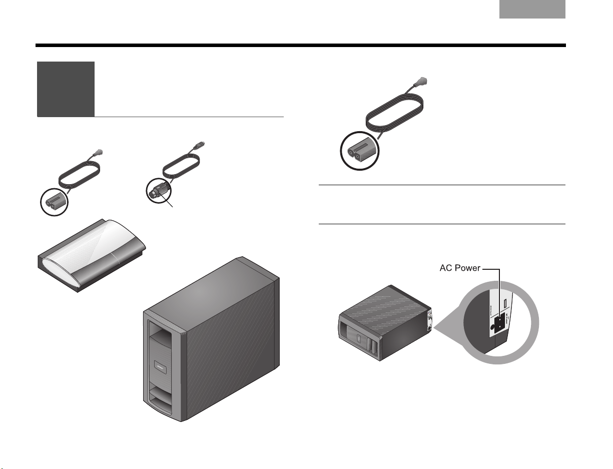
3
Connecting
the module
1. Choose the AC power cord.
CAUTION: Do not plug the power cord into an AC
(mains) outlet until all connections to the system are
completed.
2. Locate the connector labeled AC Power on the
Acoustimass module connection panel.
16
Page 21
TAB 5TAB 4TAB 6TAB 8TAB 7English TAB 3TAB 2
Arrow
COMPLETE SYSTEM CONNECTIONS
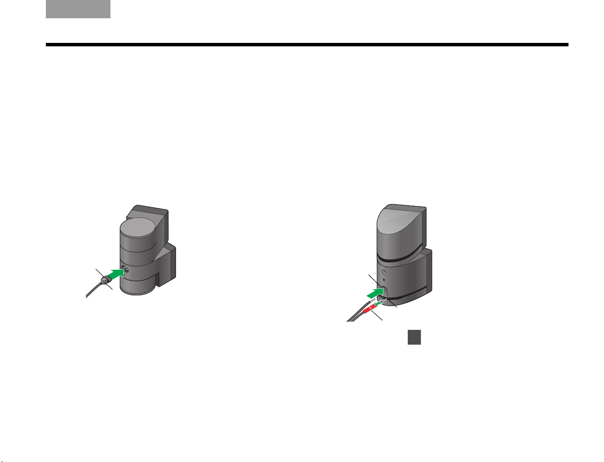
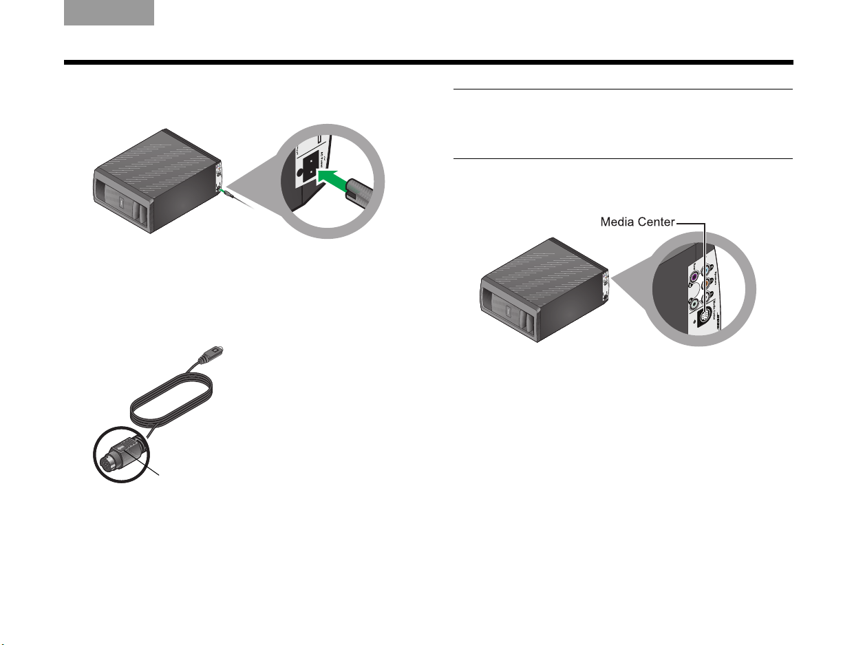
3. Insert the appropriate plug on the power cord into
the connector on the module.
4. Place the other end of the power cord near an
outlet, but do NOT plug it in at this time.
5. Choose the audio input cable that has an arrow on
the plug at each end.
CAUTION: Avoid putting strain on the plugs at either
end of the audio input cable. Pulling on the cable or
compressing it exerts excessive strain and can cause
damage.
6. Locate the connector labeled Media Center on the
Acoustimass
®
module connection panel.
17
Page 22
COMPLETE SYSTEM CONNECTIONS
Inner
edge
Arrow
Arrow
4
EnglishTAB 6TAB 8 TAB 7 TAB 3TAB 5 TAB 2TAB 4
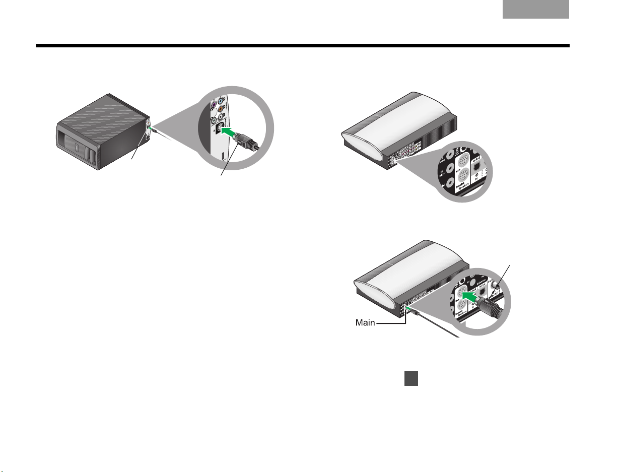
7. Insert the Audio input cable plug into this connector on the module.
Be sure the arrow on the flat side of the plug faces
the inner edge of the module.
All cables are now connected to the module. This
is a good opportunity to set the module upright or
on a side and move it into final position in your
room.
8. Locate the two connectors labeled Speakers on
the rear of the media center.
9. Insert the remaining plug on the audio input cable
into the top connector labeled Main.
Be sure that the arrow on the flat side of the plug is
facing up as you insert the plug.
10. Continue with on the next page for connections
18
to the VS-2 video enhancer.
Page 23
TAB 5TAB 4TAB 6TAB 8TAB 7English TAB 3TAB 2
What you need to use:
VS-2 video enhancer
VS-2 cable
Media center
AC power cord
Power supply
Small end
COMPLETE SYSTEM CONNECTIONS
4
Connecting
1. Choose the power supply and power cord.
the media center
CAUTION: Do not plug the power cord into an AC
(mains) power outlet until all connections to the system
are completed.
19
Page 24
COMPLETE SYSTEM CONNECTIONS
Power
supply
cable
EnglishTAB 6TAB 8 TAB 7 TAB 3TAB 5 TAB 2TAB 4
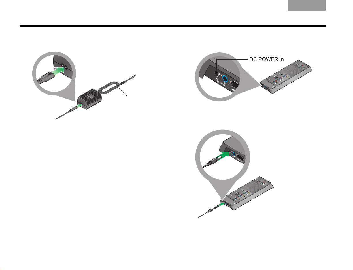
2. Plug the small end of the AC power cord into the
connector on the end of the DC power supply.
If you have a dual-voltage power supply:
MAKE SURE the voltage selection switch on the
bottom of the power supply is set properly for the
local power rating.
Check with local electrical authorities if you are not
sure of the appropriate power rating.
3. Place the other end of the power cord near an AC
power outlet, but do NOT plug it in at this time.
4. Locate the connector labeled DC POWER In on
one end of the VS-2 video enhancer.
5. Insert the power supply cable plug into the VS-2
connector.
20
Page 25
TAB 5TAB 4TAB 6TAB 8TAB 7English TAB 3TAB 2
Small plug
COMPLETE SYSTEM CONNECTIONS
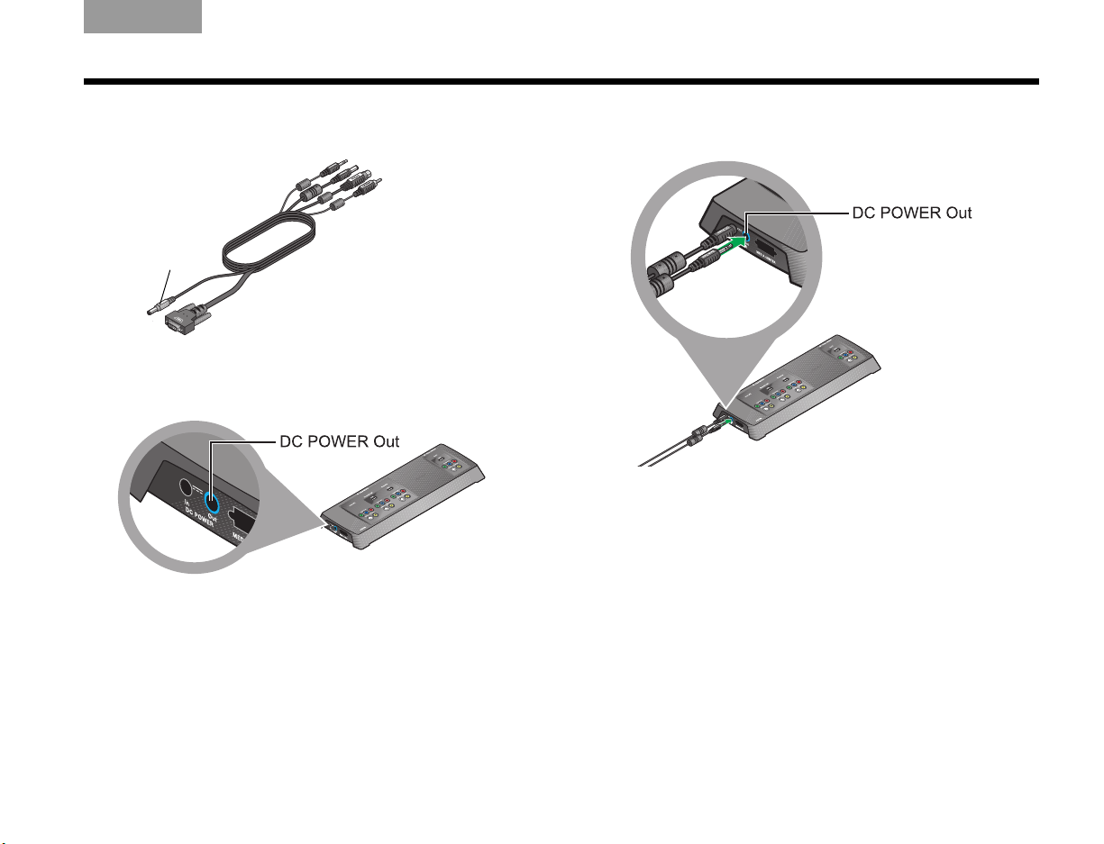
6. Choose the VS-2 cable and notice the small plug at
one end.
7. Locate the connector labeled DC POWER Out on
the VS-2 video enhancer.
8. Insert the gray plug labeled DC Power into this
connector.
Important Note: The two power cables that plug into
the end of the VS-2 contain antennas for the radio
frequency (RF) remote control.
BE SURE to fully extend both cables and keep them
away from other system cables as much as possible.
21
Page 26
COMPLETE SYSTEM CONNECTIONS
White
symbol
Thumb
screw
Large
cylinder
EnglishTAB 6TAB 8 TAB 7 TAB 3TAB 5 TAB 2TAB 4
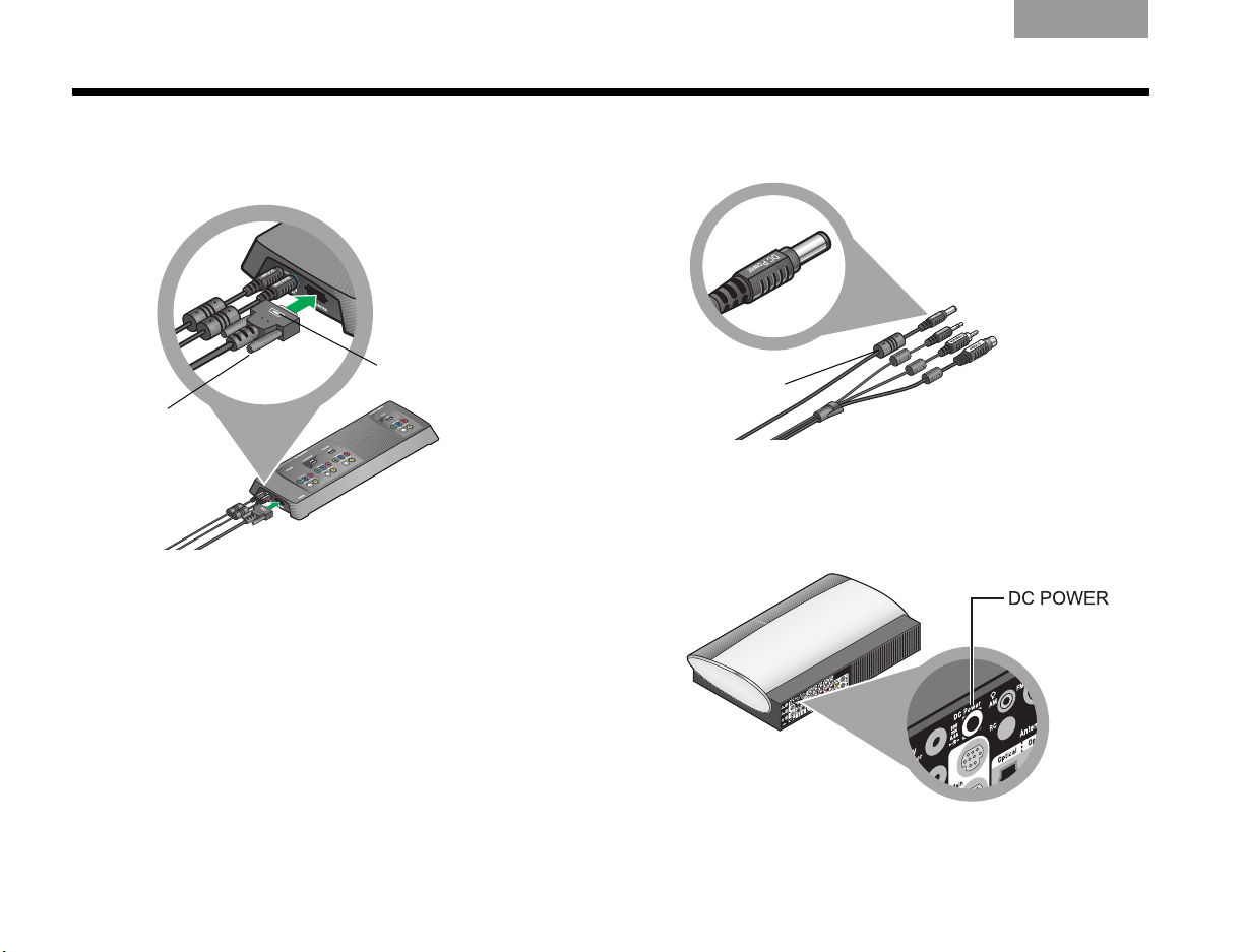
9. Attach the large plug on the cable, with the white
symbol facing up, into the remaining connector on
the VS-2 connector.
Be sure to tighten the thumb screws on either side
of the plug to secure it.
10. At the other end of the VS-2 cable, locate the plug
labeled DC power.
The cable for this plug has a large cylinder
attached.
11. On the rear of the media center, locate the
connector labeled DC Power.
22
Page 27
TAB 5TAB 4TAB 6TAB 8TAB 7English TAB 3TAB 2
COMPLETE SYSTEM CONNECTIONS
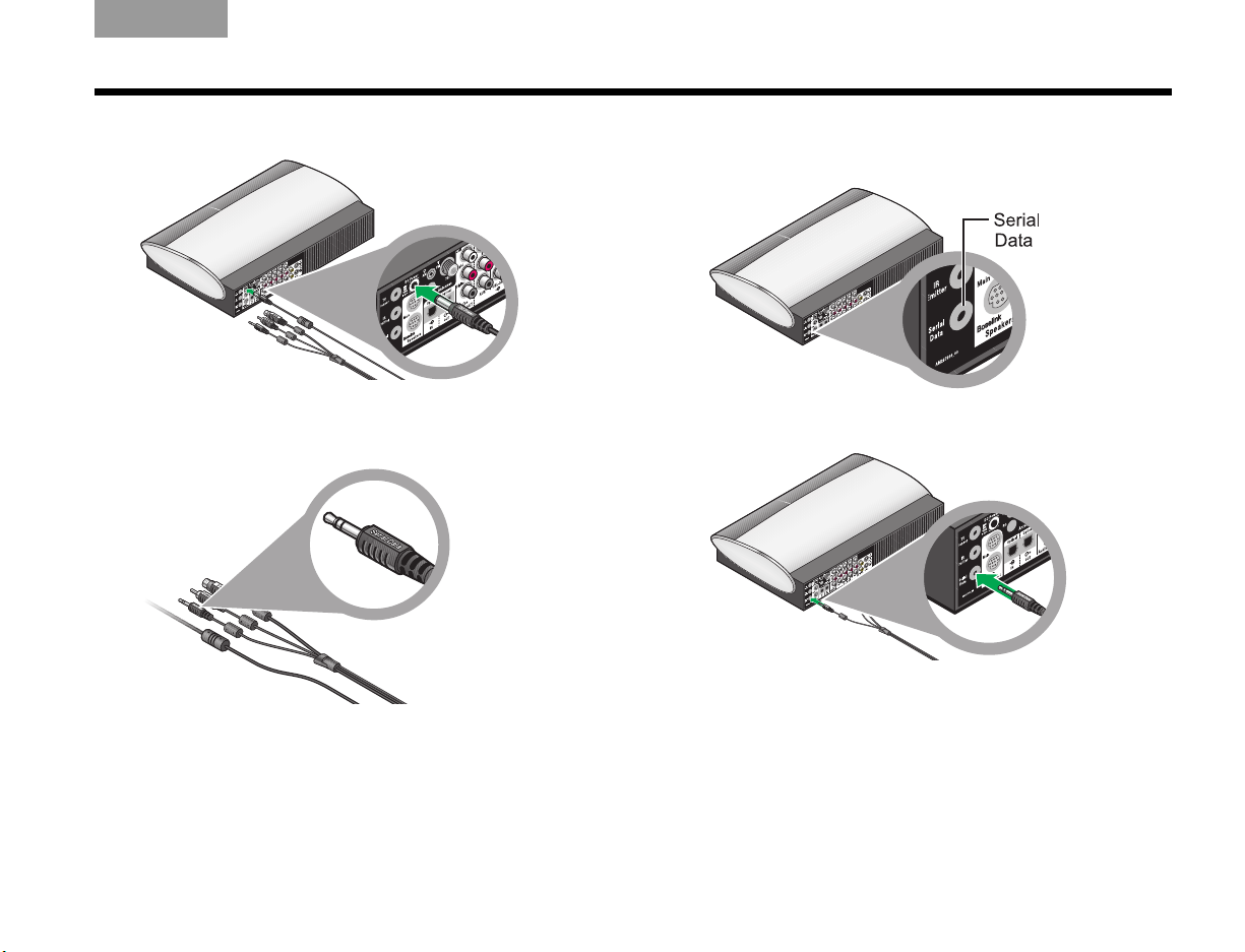
12. Insert the DC Power plug into this connector.
13. From the remaining three plugs on this cable,
choose the one labeled Serial Data.
14. Locate the connector labeled Serial Data on the
media center.
15. Insert the Serial Data plug into this connector.
23
Page 28
COMPLETE SYSTEM CONNECTIONS
5
EnglishTAB 6TAB 8 TAB 7 TAB 3TAB 5 TAB 2TAB 4
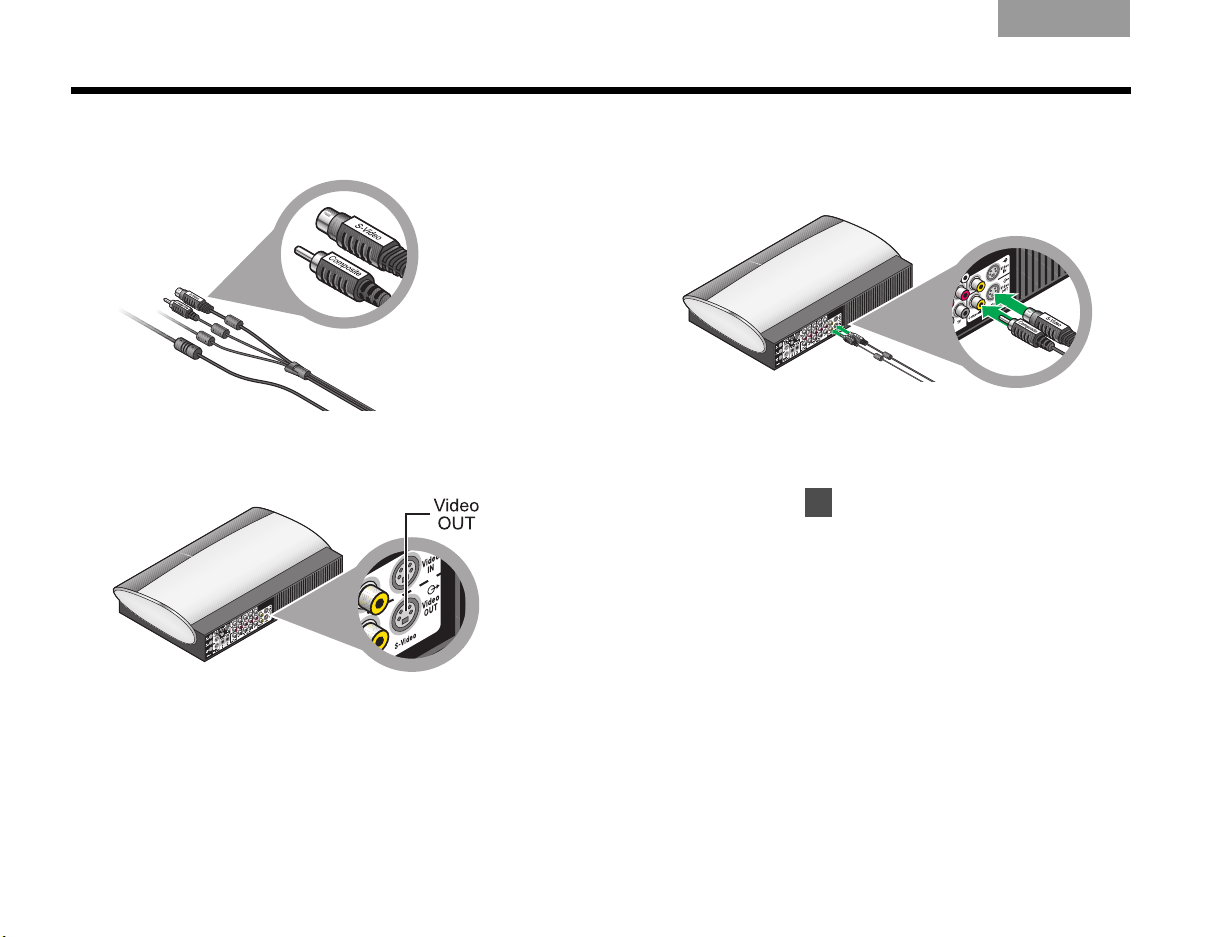
16. Notice that the two remaining plugs are labeled
Composite and S-Video.
17. On the rear panel of the media center, locate the
Video OUT connectors.
18. Insert the two video plugs, with their labels facing
up, into the appropriate Video OUT connectors on
the media center.
Check to be sure that the two cable plugs are
inserted into the lower Video OUT connectors, and
NOT into Video IN.
19. Continue with on the next page to begin
preparing your TV for use with the system.
24
Page 29
TAB 5TAB 4TAB 6TAB 8TAB 7English TAB 3TAB 2
Disconnect all of the video devices, like a cable or
satellite box, from your TV.
• Remove both the audio and video cables at the TV
end only.
Disconnect video
and audio cables
from your TV
COMPLETE SYSTEM CONNECTIONS
Disconnecting your
devices from the TV
5
• Leave the other end of the audio and video cables
connected to your video devices.
• Do NOT disconnect any antenna or power cables
from your TV.
Note: Later instructions will show you how to attach the
video cables from each device to the VS-2 connection
panel and the audio cables to the media center.
25
Page 30
COMPLETE SYSTEM CONNECTIONS
What you need to use:
VS-2 video enhancer
Your TV
HDMI cable
(provided by Bose)
EnglishTAB 6TAB 8 TAB 7 TAB 3TAB 5 TAB 2TAB 4
6
Connecting
your TV
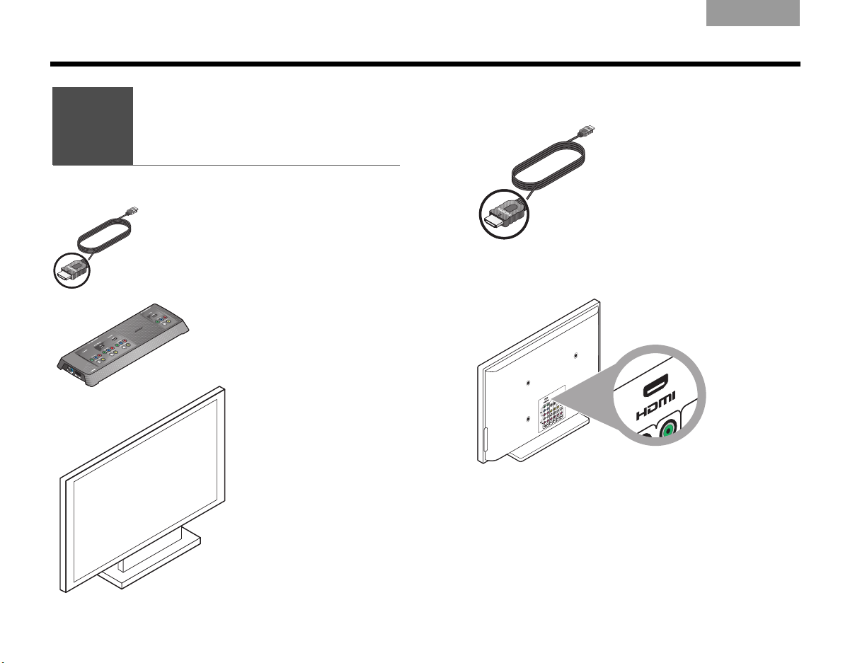
1. Notice the type of plug at either end of the HDMI
cable.
2. Check to be sure your TV has an HDMI
connector that accepts this type of plug.
• If you find an HDMI connector, continue with
step 3.
26
• If there is no HDMI connector on your TV, skip to
“If an HDMI connection is not possible” on
page 28.
Page 31
TAB 5TAB 4TAB 6TAB 8TAB 7English TAB 3TAB 2
7
COMPLETE SYSTEM CONNECTIONS
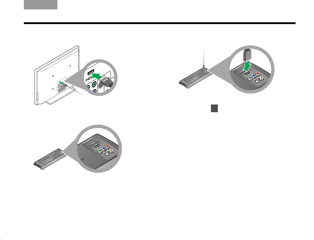
3. Plug one end of the HDMI cable into the HDMI
connector on your TV.
4. Locate the Video OUTPUT area on the VS-2
connection panel.
5. Plug the free end of the HDMI cable into the HDMI
Video OUTPUT connector.
6. When your connection to the TV is completed,
continue with on page 29 for other
connections.
27
Page 32

COMPLETE SYSTEM CONNECTIONS
Red
Blue
Green
Excellent
Good
Yellow
Basic
TV
Video In
VS-2 Video OUTPUT
Video cable
EnglishTAB 6TAB 8 TAB 7 TAB 3TAB 5 TAB 2TAB 4
If an HDMI connection is not possible
1. Check the Video In connectors on your TV.
It may have one or more of these:
Possible connectors Cables that match
Note: If your TV requires a SCART connection, used in
Europe only, refer to “Connections: For TVs requiring
SCART (in Europe, only)” on page 64.
2. Choose the highest grade of cable your TV can
accept.
3. Use this cable to connect the Video In on your TV
to the Video OUTPUT on the VS-2.
The grade of cable you use determines the highest
video resolution you can get.
28
Page 33

What you need to use:
2nd HDMI
cable
Component
cable
S-Video
cable
Composite
cable
Red, green, blue
Yellow
Available at
electronics stores
VS-2 video enhancer
Media center
Stereo
cable
Optical
cable
Your video device
(cable or satellite box,
for example)
OR
OR
OR
White, red
7
TAB 5TAB 4TAB 6TAB 8TAB 7English TAB 3TAB 2
COMPLETE SYSTEM CONNECTIONS
Connecting another device
(cable or satellite box, VCR, or DVR)
29
Page 34

COMPLETE SYSTEM CONNECTIONS
Disconnected audio
and video cables
EnglishTAB 6TAB 8 TAB 7 TAB 3TAB 5 TAB 2TAB 4
Connecting the video from your cable or satellite box first
This connection carries the video from your device to
your TV. You will make the audio connection after this.
1. Locate your cable or satellite box connection
panel.
2. Decide which connector you will use:
a. If a cable still connects the box to your TV, refer
to “Disconnecting your devices from the TV” on
page 25.
Make sure all audio and video cables are disconnected from the TV.
Then continue with b.
b. If there is a video cable connected to the cable
box and one end is now free (disconnected from
your TV), use this cable and follow step 5 on
page 31.
c. If the cable box does not have a video cable
attached, notice the type of Video Out connector the box provides. Then follow steps 3-5.
30
Page 35

TAB 5TAB 4TAB 6TAB 8TAB 7English TAB 3TAB 2
Red, blue,
and green
Yellow
Video Out
From
CBL-SAT
COMPLETE SYSTEM CONNECTIONS
3. Choose a cable that matches the Video Out
connector on the box.
If there is more than one possibility, select the one
cable that best fits your needs:
HDMI
• Most advanced video
• For use only if your TV is
connected to the VS-2 video
enhancer using HDMI
Component
• Excellent video
• For use only if your TV is
connected to the VS-2 video
enhancer using component or
HDMI
S-Video
• Good video
• For use regardless of how
your TV is connected to the
VS-2 video enhancer
S-Video
• Basic video
• For use regardless of how
your TV is connected to the
VS-2 video enhancer
4. Connect this cable to the matching Video Out
connector on the box.
5. Connect the other end of the cable to the matching
connector labeled From CBL-SAT on the VS-2.
31
Page 36

COMPLETE SYSTEM CONNECTIONS
White
Red
White
Red
Be sure to match the
colors on the plugs to
the connector colors:
red to red (R) and white
to white (L).
EnglishTAB 6TAB 8 TAB 7 TAB 3TAB 5 TAB 2TAB 4
Adding audio from your cable or satellite box
You need to make this connection regardless of the
type of video connection (HDMI for example) you used.
This carries the audio from your device to your Bose
system speakers.
1. Check your cable or satellite box connection panel
to locate the Audio Out connectors.
2. Identify the stereo audio cable to use:
a. If a stereo audio cable still connects the box to
your TV, refer to “Disconnecting your devices
from the TV” on page 25. Proceed to b, below.
b. If the cable connected to the box is free at one
end (disconnected from the TV), proceed to
step 3.
32
c. If a stereo audio cable is not yet attached, use
the cable provided by Bose and connect one
end to the Audio Out connector on your box.
®
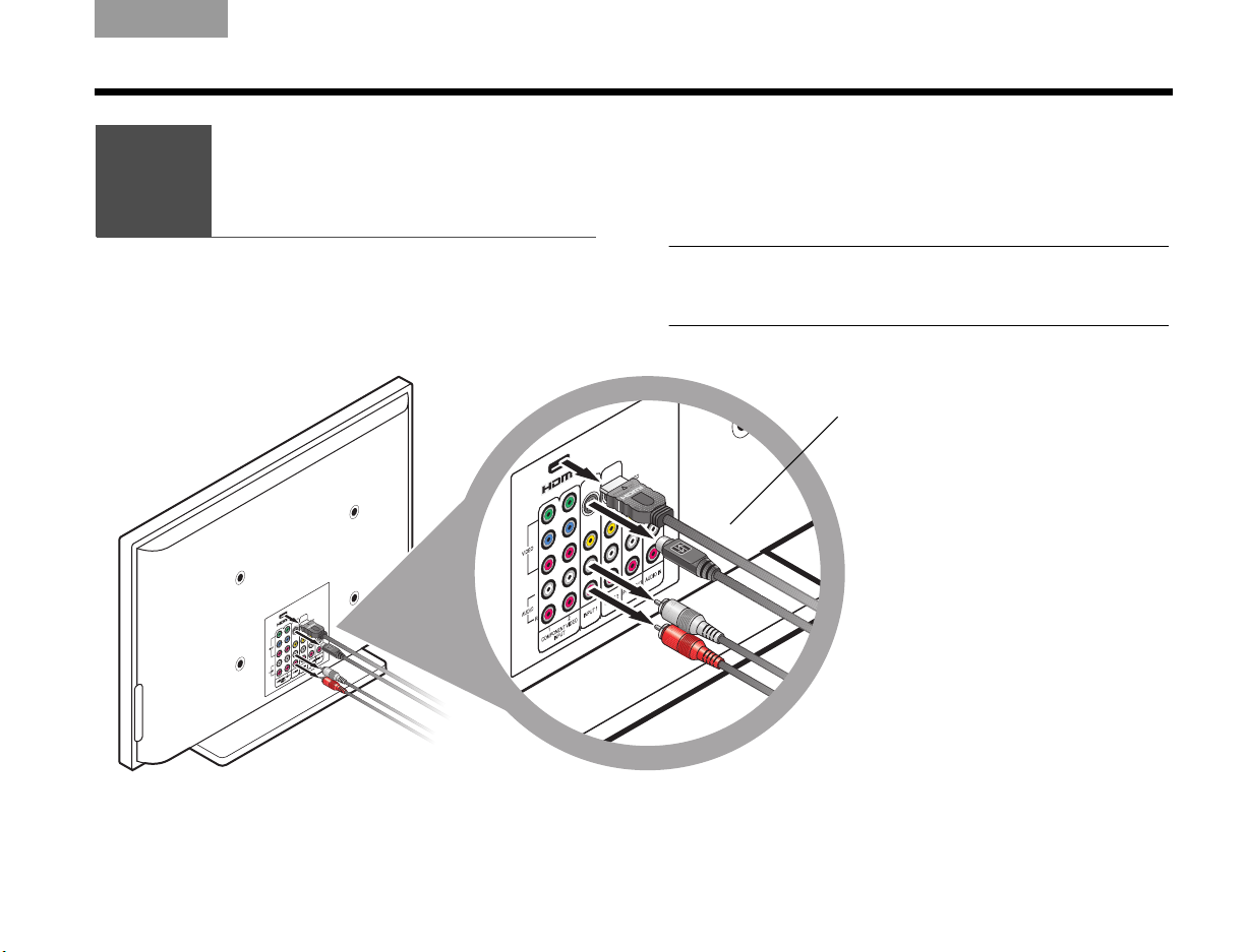
3. Locate the Audio IN connectors that are labeled
CBL•SAT on the back of the media center.
These connectors are between the VCR and AUX
Audio IN connectors.
4. Insert the free end of the stereo cable into the top
two connectors.
Be sure to match the colors on the plugs to the
connector colors: red to red (R) and white to
white (L).
Page 37

TAB 5TAB 4TAB 6TAB 8TAB 7English TAB 3TAB 2
Cap
COMPLETE SYSTEM CONNECTIONS
Including a digital audio connection
In addition to the stereo connection, you can make a
high-quality digital audio connection if your device
provides such a connector.
Note: To avoid temporary loss of audio (common signal
drop outs during digital transmissions), keep the stereo
audio cable connected to your device and the media
center. This allows for uninterrupted audio performance.
1. Check to see if your device has a digital audio
connector. It can be:
• An optical connector that uses optical cable.
This cable is provided in the carton.
Be sure to remove the plastic cap from each
plug.
• A coaxial (COAX) connector that uses a simple
COAX or RCA cable (like the composite cable
included in the carton).
2. Using the appropriate cable, insert one end into the
digital audio connector on your device.
3. Insert the other end of the cable into either:
• The Optical IN connector on the media center.
• The coaxial connector for CBL•/SAT, VCR, or
AUX on the media center.
Note: For an optical connection to a device other than
a cable or satellite box, you need to set the system to
recognize the signal from this other device.
This cable is available at electronics stores.
Refer to “Other system options” on page 59.
33
Page 38

COMPLETE SYSTEM CONNECTIONS
White
Red
Be sure to match the
colors on the plugs to
the connector colors:
red to red (R) and white
to white (L).
8
EnglishTAB 6TAB 8 TAB 7 TAB 3TAB 5 TAB 2TAB 4
Adding more devices
You may want to have another device like a VCR or
DVR work with this system.
This is basically a repeat of the process for adding a
cable or satellite box. Simply substitute this other
device as you follow instructions beginning with
“Connecting the video from your cable or satellite box
first” on page 30.
1. Consider these points.
• For each device, you need to use a video cable
and a stereo audio cable.
• The video cable you use must be compatible
with the cable that connects the VS-2 to your TV.
For details on compatible video cable, refer to
page 31.
2. Use a video cable and connect it to Video Out on
your device. Connect the other end to the Video In
for either VCR (for video recording) or AUX on the
VS-2.
3. Use a stereo audio cable and connect it to Audio
Out on your device.
4. On the media center, locate the AUX or VCR Audio
IN connector.
• If you use the AUX connector, the button labeled
AUX on the LIFESTYLE
®
remote controls your
device.
• If you use the VCR connector, the button labeled
VCR controls this device. The VCR button
includes an On/Off control.
5. Connect the other end of the stereo audio cable to
the Audio IN connector on your media center.
Note: All cables are now connected to the VS-2 video
enhancer. This is a good opportunity to move the VS-2
into place, behind or very near the media center.
6. Continue with on the next page for further
connections.
34
Page 39

What you need to use:
IR emitter
Your TV
TV sensor
Media center
8
Attaching
the IR emitter
and TV sensor
TAB 5TAB 4TAB 6TAB 8TAB 7English TAB 3TAB 2
COMPLETE SYSTEM CONNECTIONS
The IR emitter relays remote control commands to the
devices that are connected to the media center. And the
TV sensor adds an automatic on/off feature for your TV.
1. Locate the connector labeled IR Emitter on the
back of the media center.
2. Insert the IR emitter plug into this connector and
center the other end in front of your TV.
35
Page 40

COMPLETE SYSTEM CONNECTIONS
Plug
9
EnglishTAB 6TAB 8 TAB 7 TAB 3TAB 5 TAB 2TAB 4
3. Identify the plug end of the TV sensor.
4. Locate the TV sensor connector on the media
center.
5. Insert the TV sensor plug into this connector.
6. Place the other end of the sensor near your TV for
use in later instructions.
7. Continue with on the next page.
36
Page 41

What you need to use:
AM antenna
FM antenna
Media center
Connecting
the AM and
FM antennas
9
TAB 5TAB 4TAB 6TAB 8TAB 7English TAB 3TAB 2
COMPLETE SYSTEM CONNECTIONS
For radio reception of broadcast radio programs,
you need to use the supplied antennas.
For FM:
1. Select the FM antenna.
2. Locate the FM antenna connector on the media
center and insert the FM antenna plug into this
connector.
37
Page 42

COMPLETE SYSTEM CONNECTIONS
10
EnglishTAB 6TAB 8 TAB 7 TAB 3TAB 5 TAB 2TAB 4
3. Straighten the antenna cable and spread the two
ends far apart.
You may need to raise the ends and adjust the
position to get clear reception.
For AM:
1. Select the AM antenna and stand.
2. Locate the AM antenna connector on the media
center and insert the AM antenna plug into this
connector.
3. Fit the small tabs on the antenna ring into notches
on the stand and press firmly to attach them.
4. Continue with on the next page for completing
power connections.
38
Page 43
TAB 5TAB 4TAB 6TAB 8TAB 7English TAB 3TAB 2
11
COMPLETE SYSTEM CONNECTIONS
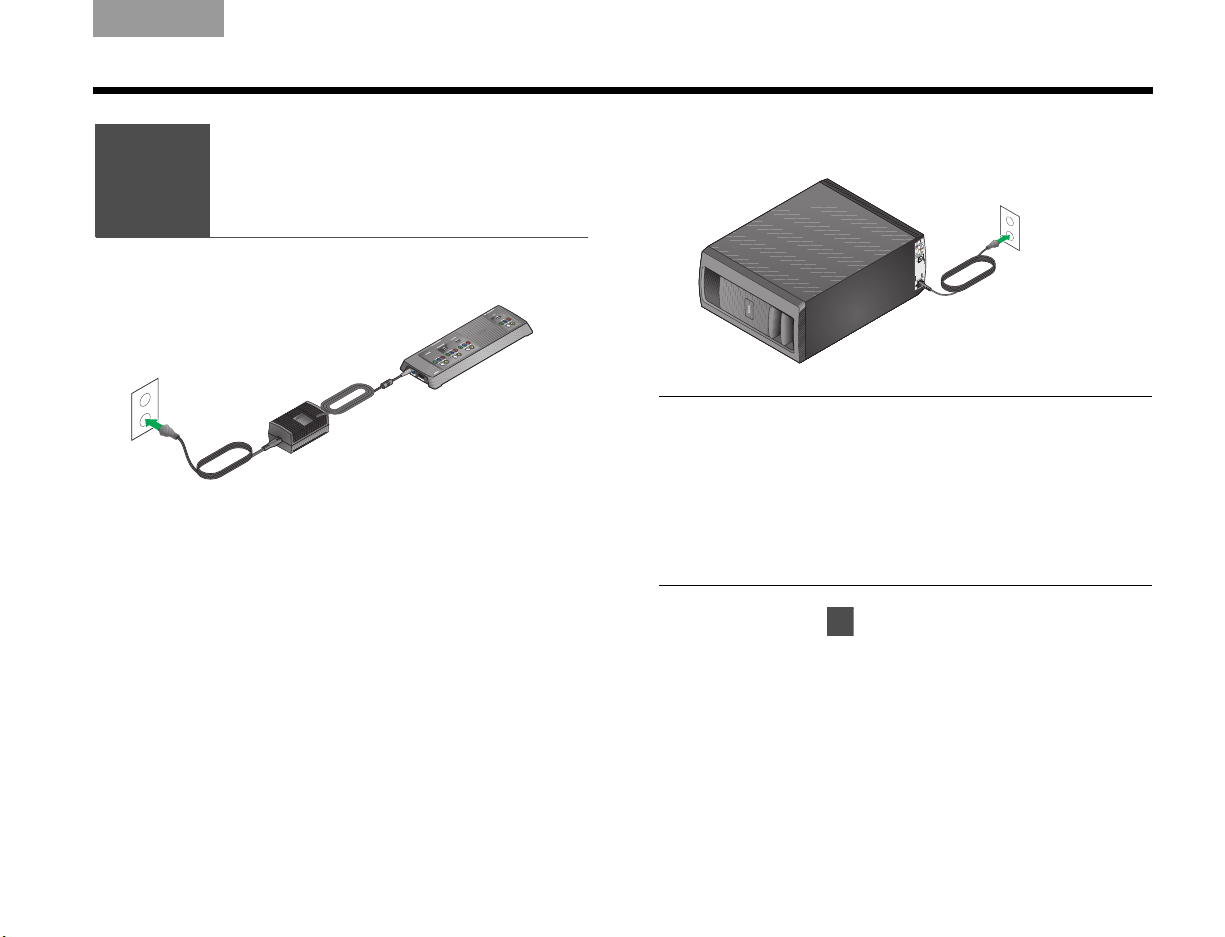
Connecting
the system
10
1. Plug the free end of the VS-2 power cord into an
AC (mains) outlet.
2. Place the power supply on the floor well below the
media center.
If you are using a plasma TV, move the power
supply as far from your TV as is practical.
to power
3. Plug the free end of the Acoustimass
into an AC (mains) outlet.
Note: Bose recommends using a high-quality surge
suppressor on all electronics equipment. Such suppressors can eliminate the vast majority of failures attributed
to surges and may be purchased at electronics stores.
Voltage variations and spikes can damage electronic
components in any system, resulting in damage not
covered by the limited warranty.
4. Continue with on the next page for getting the
remote control ready.
®
power cord
39
Page 44

COMPLETE SYSTEM CONNECTIONS
What you need to use:
Your TV
LIFESTYLE® remote
control and batteries
Any other
connected devices
Setting the remote
to control your TV
and other devices
11
EnglishTAB 6TAB 8 TAB 7 TAB 3TAB 5 TAB 2TAB 4
You can set your LIFESTYLE
and other components connected to the media center.
®
remote to control your TV
Inserting the remote batteries
The four supplied AA batteries go into the compartment
on the back of the remote control.
1. Slide the battery compartment cover off and insert
the batteries.
Match the + symbols on each battery to + marks
inside the battery compartment.
2. Slide the cover back until it clicks into place.
3. Use the On/Off button on the remote to turn on
your LIFESTYLE
You do not need to aim the remote at the system.
®
system.
40
4. Use controls on the TV and your other devices to
turn them on.
Page 45

TAB 5TAB 4TAB 6TAB 8TAB 7English TAB 3TAB 2
System
button
ENTER button
Source
buttons
Directional
arrows
COMPLETE SYSTEM CONNECTIONS
Making it a universal remote
Your LIFESTYLE® remote can control most devices that
are connected to the system.
To use it as a universal remote, you need to set the
remote for each of these devices, including your TV.
For this procedure, you will use the remote:
• Source buttons
• System button
• ENTER button
• Directional arrows
Setting the remote for TV control
You can use the LIFESTYLE® remote for basic control of
your TV, like turning it on and off and changing
channels.
Whenever you select a video source to watch, you can
also have the TV turn on automatically. This requires
using the TV sensor.
To prepare the LIFESTYLE
Most TVs can receive IR signals from the LIFESTYLE
remote with no problem. For best results, however,
position the IR emitter in front of the TV.
For details, refer to “Attaching the IR emitter
and TV sensor” on page 35.
1. Use your TV remote to turn on your TV.
2. Using the LIFESTYLE
TV source button.
This turns on the system and selects your TV.
3. Press the System button.
The Bose
®
System menu appears on the TV
screen.
If you do not see the menu on screen, use the TV
remote to change inputs on the TV.
Refer to your TV instruction guide for details.
®
remote
®
remote control, press the
®
41
Page 46

COMPLETE SYSTEM CONNECTIONS
Select your TV brand.
TV Brand:
TV Code:
CBL• SAT Device:
CBL• SAT Brand:
CBL• SAT Code:
VCR Device:
VCR Brand:
VCR code:
- -
Remote Control
navigate
select
Select your TV brand.
TV Brand:
TV Code:
CBL• SAT Device:
CBL• SAT Brand:
CBL• SAT Code:
VCR Device:
Philex
Philharmonic
Philips
Phoenix
Phonola
navigate
select
Remote Control
EnglishTAB 6TAB 8 TAB 7 TAB 3TAB 5 TAB 2TAB 4
Note: The text in the System menu appears in English,
but other languages are provided. To select one of the
eight other languages, see “Changing system and source
settings” on page 57.
4. Press the right arrow button to move to the
Remote Control icon and press the ENTER button
to move into the menu.
5. Move right to see the alphabetic list of TV brands.
6. Move up or down the list to locate the brand of
your TV.
7. Press ENTER to select your brand.
42
Page 47

TAB 5TAB 4TAB 6TAB 8TAB 7English TAB 3TAB 2
navigate
select
Choose “Automatic” to enable this feature.
TV Power:
TV Power Status:
TV Aspect Ratio:
Widescreen DVDs:
Video Connector:
Video Black Level:
Automatic
TV Not Detected
- -
- Component
Normal
Video
COMPLETE SYSTEM CONNECTIONS
8. Move down the list to TV Code and right to see the
first code.
9. Press the TV On/Off button on your
LIFESTYLE
button again.
• If the TV turns off and on, you have
chosen a code that works. Try changing channels to make sure this code gives you full control.
• If the TV does not turn off or does not respond to
other controls, select another code and check
again to make sure it works.
10. When you have chosen the right code, press
ENTER.
11. Move up to the top line of icons in the System
menu to set the TV for automatic on/off.
To set the TV for automatic on/off
1. With the System menu on your TV screen, move
across to the Video icon.
2. Press the ENTER button to move into the menu
and select TV Power.
®
remote. Then press this
3. Move right, then up or down to select Automatic
and press the ENTER button.
4. Temporarily hold the free end of the TV sensor in
place on the back of your TV.
Holding it near the heat vents or power cord on the
TV may work best.
For a projection TV, holding it near the bottom rear
of the chassis may work best.
43
Page 48

COMPLETE SYSTEM CONNECTIONS
12
EnglishTAB 6TAB 8 TAB 7 TAB 3TAB 5 TAB 2TAB 4
5. On the TV screen, look at the menu item TV Power
and see if it shows TV Detected.
If so, the sensor is connected and positioned properly on the TV.
You can now use the adhesive pad to attach the
sensor at that spot. Then move to step 6 below.
If you see:
• TV Not Detected, the TV sensor is not connected
or not positioned properly.
Check the connection on the media center, then
move the sensor and check for TV Detected on
the screen. If you see it, move to step 6.
• If repositioning the sensor does not work, you can
still use the LIFESTYLE
®
remote with your TV.
Simply use the TV On/Off button, instead of
having the TV turn on automatically.
6. Follow the steps in “Setting the remote for cable or
satellite” next.
Or, press the System or Exit button to dismiss the
system menu from your TV screen.
Then continue with on page 47 for fine tuning
your setup.
Setting the remote for cable or satellite
You can use the remote to turn on and make basic
selections on your other devices.
Most cable or satellite devices can receive IR signals
from the LIFESTYLE
results, however, position the IR emitter in front of your
device (if it is not already in use for the TV).
Note: If you need to obtain another IR emitter, contact
Bose. Refer to the address list included in the carton.
To control a device connected to CBL•SAT
1. Use the cable or satellite remote to turn on your
device.
2. Using the LIFESTYLE
press the CBL•SAT source button.
This selects the device and turns on the
system if it was off.
3. Press the System button and move right to the
Remote Control icon.
4. Press ENTER to move into this menu.
®
remote with no problem. For best
®
remote control,
44
Page 49

TAB 5TAB 4TAB 6TAB 8TAB 7English TAB 3TAB 2
Select the kind of device that is connected to the
CLB•SAT input.
TV Brand:
TV Code:
CBL• SAT Device:
CBL• SAT Brand:
CBL• SAT Code:
VCR Device:
VCR Brand:
VCR code:
--
Remote Control
navigate
select
-TV
Satellite
Satellite/DVR
Cable
Cable/DVR
TV Brand:
TV Code:
CBL• SAT Device:
CBL• SAT Brand:
CBL• SAT Code:
VCR Device:
navigate
select
Remote Control
Select the kind of device that is connected to the
CLB•SAT input.
COMPLETE SYSTEM CONNECTIONS
5. Move down the list of options to Cable•Sat Device. 6. Move right and then up or down the list to locate
the type of device you are using.
7. Press ENTER to select the device.
8. Move down the list of options to CBL•SAT Brand.
9. Move right to see the list of brands and press
ENTER to select your brand.
10. Move down the list of options to CBL•SAT Code.
11. Move right to select the first code in the list.
45
Page 50

COMPLETE SYSTEM CONNECTIONS
12
12
EnglishTAB 6TAB 8 TAB 7 TAB 3TAB 5 TAB 2TAB 4
12. Press the CBL•SAT On/Off button on your
LIFESTYLE
®
remote. Press this button
again.
• If the device turns off and on, you have chosen a
code that works. Try changing channels to make
sure this code gives you full control.
• If your device does not turn off or does not
respond to other controls, select another code
and check again to make sure it works.
13. When you have the right code, press ENTER.
14. Follow the steps in “Setting the remote for another
device” next.
Or, press the System or Exit button to dismiss the
system menu from your TV screen.
15. Then continue with on page 47 for fine tuning
your setup.
Setting the remote for another device
Follow the steps used to set the remote for CBL•SAT,
but with these changes.
For VCR:
1. Using the LIFESTYLE
VCR button to select the source and turn on
the system if it is off.
2. Turn on your VCR device and set the options for
VCR in the Remote Control menu.
3. Use the VCR On/Off button on the LIFESTYLE
remote to make sure the code works.
For AUX:
1. Using the LIFESTYLE
button to select the source and turn on the system
if it is off.
2. Turn on your AUX device and set the options for
AUX in the Remote Control menu.
3. Use the Channel or Volume button on the
LIFESTYLE
®
remote to make sure the code works.
4. Continue with on the next page for fine tuning
your setup.
®
remote, press the
®
remote, press the AUX
®
46
Page 51

What you need to use:What you need to use:
ADAPTiQ® kit carton,
which includes:
Disc 1
Disc 2
ADAPTiQ
audio calibration
headset
Media center
Tailoring the sound
to your room
12
TAB 5TAB 4TAB 6TAB 8TAB 7English TAB 3TAB 2
COMPLETE SYSTEM CONNECTIONS
Getting the sound you want
The Bose® ADAPTiQ audio calibration system adds the
final touch to your system setup.
Use this kit to verify your speaker positions and tailor
the sound to the particular audio character of your
room.
For its effective use:
• Schedule this process when others will not be
disturbed by the acoustic tones that are used for
measurements.
• Allow about 30 minutes to complete the process.
• Choose a time when you will not be disturbed by
voices, phone calls, or other sound interruptions.
• Make sure your LIFESTYLE
where you want them and your room furnishings are
in their normal positions.
®
speakers are positioned
47
Page 52

COMPLETE SYSTEM CONNECTIONS
AUX
L & R
Headset
EnglishTAB 6TAB 8 TAB 7 TAB 3TAB 5 TAB 2TAB 4
Beginning the process
1. Plug the headset cable into the AUX connector on
the media center.
Be sure to match the colors on the plugs to the
colors on the connectors: red to red and white to
white.
Note: If you have another device connected to the AUX
input, temporarily disconnect it.
2. Lay the headset close to where you watch TV.
Do not put on the headset until the instructions
indicate this.
4. On the media center, lift the front cover and press
the Open/Close button to open the disc drive.
5. Insert Disc 1 into the drive and press Open/Close
again.
6. On the LIFESTYLE
®
remote control, press the
CD•DVD button.
This turns on the system and begins to play the
DVD.
A Bose
®
image should appear on screen. If it does
not, change the TV Video Input until the picture
appears.
7. Watch the DVD until you hear instructions to
replace Disc 1 with Disc 2.
3. Turn on your TV.
48
Page 53

TAB 5TAB 4TAB 6TAB 8TAB 7English TAB 3TAB 2
COMPLETE SYSTEM CONNECTIONS
Finishing the process
1. With Disc 2 inserted in the media center disc drive,
press the CD•DVD button on the remote control.
2. Listen for instructions for putting on the headset.
The headset is designed to be worn above your
ears for accurate acoustic measurements.
3. When the disc finishes, press the Open/Close
button on the media center and remove the disc.
4. Unplug the headset cable from the rear of the
media center.
If you disconnected a device from the AUX
Audio In connector, you can reconnect it now.
5. Return the headset and both discs to the kit carton
for possible future use.
Storing any parts you do not need
We suggest you save any of the LIFESTYLE® carton
contents that you are not using.
These include:
• The ADAPTiQ
If you rearrange your room or move your system
speakers, we suggest running the ADAPTiQ audio
calibration system again.
• Video cables you did not use for initial setup
When you purchase new video devices, you may
need these cables to make the added connections.
• This owner’s guide when you have finished using it
The operating instructions may be useful over the
long term.
If you move the system, you may need instructions to
redo the connections.
• The list of Bose
warranty card, and purchase receipt
These are useful if you ever need assistance with
your system or want to order accessories.
®
kit
®
Customer Service addresses, your
Congratulations!
With your system set up successfully, you can now
move on to “Using and Enjoying Your System” on
page 50.
49
Page 54

USING AND ENJOYING YOUR SYSTEM
Source
buttons
and their
On/Off controls
System
On/Off
button
EnglishTAB 6TAB 8 TAB 7 TAB 3TAB 5 TAB 2TAB 4
Introducing the basics
Before you explore the variety of play options, here are
some basics on controlling your new LIFESTYLE
home entertainment system.
Turning on the system
• Press the On/Off button on the LIFESTYLE® remote
control or on the media center front panel.
This turns the system on to the previously used
source.
• Or, press one of the Source buttons (Stored*,
CD•DVD, FM•AM, AUX, TV, CBL•SAT, TV, or VCR)
on the remote control.
This turns on the system and selects this source for
play.
®
DVD
Turning on your TV
• If your LIFESTYLE® remote is set to control the TV,
press the TV On/Off button.
If the TV sensor is installed and functioning, your TV
will turn on automatically when you press one of the
video source buttons (such as TV, CBL•SAT, or VCR).
• If your LIFESTYLE
®
remote is not set to control the
TV, use the TV remote to turn your TV on and off.
Getting the sound for your video
Set your TV volume very low so you can hear sound
only from your LIFESTYLE
®
system speakers.
Getting the video to appear
To see the picture on your TV screen, you need to
select the input on your TV that connects to the VS-2.
Use one of these means to select the proper video
input:
• Use the LIFESTYLE
control your TV.
Press the TV Input button until you see the picture
from the LIFESTYLE
box, or your VCR.
• Or, use your TV remote control Input selection button.
®
remote control if it is set to
®
DVD, your cable or satellite
*
On Lifestyle
50
®
38 and 48 systems only.
Page 55

TAB 5TAB 4TAB 6TAB 8TAB 7English TAB 3TAB 2
Guide
Displays an on-screen
program guide if the
selected source
provides a guide.
Preset numbers
Select a:
• CD track
• DVD chapter
• A channel for
TV, cable, or satellite
• A preset radio station
for AM or FM
Info
Displays or
dismisses:
• Any cable or satellite
on-screen information
that is available.
• MP3 artist and title
information on the
media center display
when the button is
held down.
Arrows and ENTER
Make it possible
to move and make
selections on screen
or on the display.
USING AND ENJOYING YOUR SYSTEM
Using the system controls
Your system responds to:
•The LIFESTYLE
Radio frequencies eliminate the need for you to aim
the remote.
RF also allows you to adjust the volume, select a
different sound source, and apply a variety of other
play options from outside the room where the system
is located.
• The media center controls
Buttons located on the front of the media center offer
a reduced set of controls, in particular On/Off,
Volume, and Open/Close of the disc tray.
An introductory overview
Some of the buttons you will use for general system
control are shown on the next two pages.
Other buttons on the remote that control specific sound
sources are identified in the information about those
sources.
®
radio frequency (RF) remote control
The remote control
51
Page 56

USING AND ENJOYING YOUR SYSTEM
Right side view
Front view
EnglishTAB 6TAB 8 TAB 7 TAB 3TAB 5 TAB 2TAB 4
The media center
The media center provides these features.
Front panel controls
On/Off Turns the system on or off in the main room.
All Off Turns off the system and any connected
Open/Close Opens or closes the disc tray.
Source Moves through play sources to select one.
Enter Confirms the play selection or other
Erase Removes a radio station preset.
Volume Lowers or raises the volume level.
Store
(on some
models only)
speakers (located in other rooms).
on-screen DVD menu options.
Copies audio CD tracks or MP3 files into the
library.
Front panel display
When the system is turned on, the display lights up.
Indicators of the system status appear on the display.
Headphone jack
For private listening, you can connect headphones to
the right side of the media center. This mutes all of the
main room speakers.
52
Page 57

TAB 5TAB 4TAB 6TAB 8TAB 7English TAB 3TAB 2
USING THE VARIOUS SOURCES
Playing a disc
1. Press CD•DVD on the remote to select the disc
player.
This turns the system on if it was off.
2. On the media center, lift the door and press the
Open/Close button.
Insert a clean disc into the tray (label side up).
If it is not clean, the disc may unexpectedly pause.
If so, remove the disc and follow the instructions
for cleaning it (on the right).
3. Press the Open/Close button again to close the tray.
4. Press Play on the remote to start the disc.
For a DVD, you may need to press Play more than
once to move through the DVD on-screen options
and select play.
Cleaning discs
Handle discs by their edges to prevent fingerprints and
scratches.
• To remove stains or fingerprints from the surface of a
disc, use a soft, lint-free, dry cloth. Wipe in straight
movements from the center of the disc to the outside.
Do not use any chemical products; they can damage
the disc.
• To minimize exposure to dust and dirt, replace discs in
their cases after use. Store each disc in its case, out of
direct sunlight, high temperatures, and humidity.
Note: Use only a disc-compatible pen or label when (or if) you write
on the disc.
Note: With an MP3 disc, track information scrolls continuously on
the media center display. To clear this information, press and hold the
Info button on the remote. Press this button again to resume display
of this information.
53
Page 58
USING THE VARIOUS SOURCES
USING THE VARIOUS SOURCES
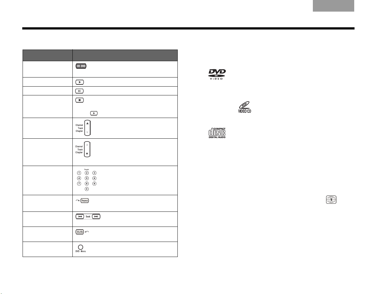
To control play Discs that are system compatible
In order to: Press:
Select the
CD•DVD player...
Play the disc...
Pause the disc… Press again to resume play.
Stop the disc… Press again to reset a DVD to the
Skip ahead… up
Skip back… down
Select a track... Press the number(s) of the track.
Repeat a CD track
or DVD chapter…
Search backward
or forward…
Randomly play CD
tracks…
See DVD menu
options...
beginning.
Press to restart a DVD or CD.
– once to restart a playing track
– twice to skip to the previous
track
while the track or chapter plays.
Press twice to repeat a playing CD.
Press again to move faster.
Your system is designed to play the following discs:
• Video DVD
•CD-R
• SACDs (CD-compatible
• Video CD
content only)
DVD-R,
DVD-RW
•MP3 CDs:
— burned in a single, closed
• Audio CD
session
— in disc format ISO9660
— with .mp3 as the extension
and no other periods in
the file name
Region codes
For any DVD player and DVD disc to work together,
the code for the region where they were sold must
match. A code symbol is marked clearly on the
bottom of your system media center and on the DVD
cover (very small). For example, Region 1 is .
Copy protection
Music and other content may be protected by
international and domestic copyright laws and
may contain specific restrictions on use and/or
reproduction. Please respect the rights of the artists
and other copyright holders.
EnglishTAB 6TAB 8 TAB 7 TAB 3TAB 5 TAB 2TAB 4
54
Page 59
TAB 5TAB 4TAB 6TAB 8TAB 7English TAB 3TAB 2
USING THE VARIOUS SOURCES
USING THE VARIOUS SOURCES
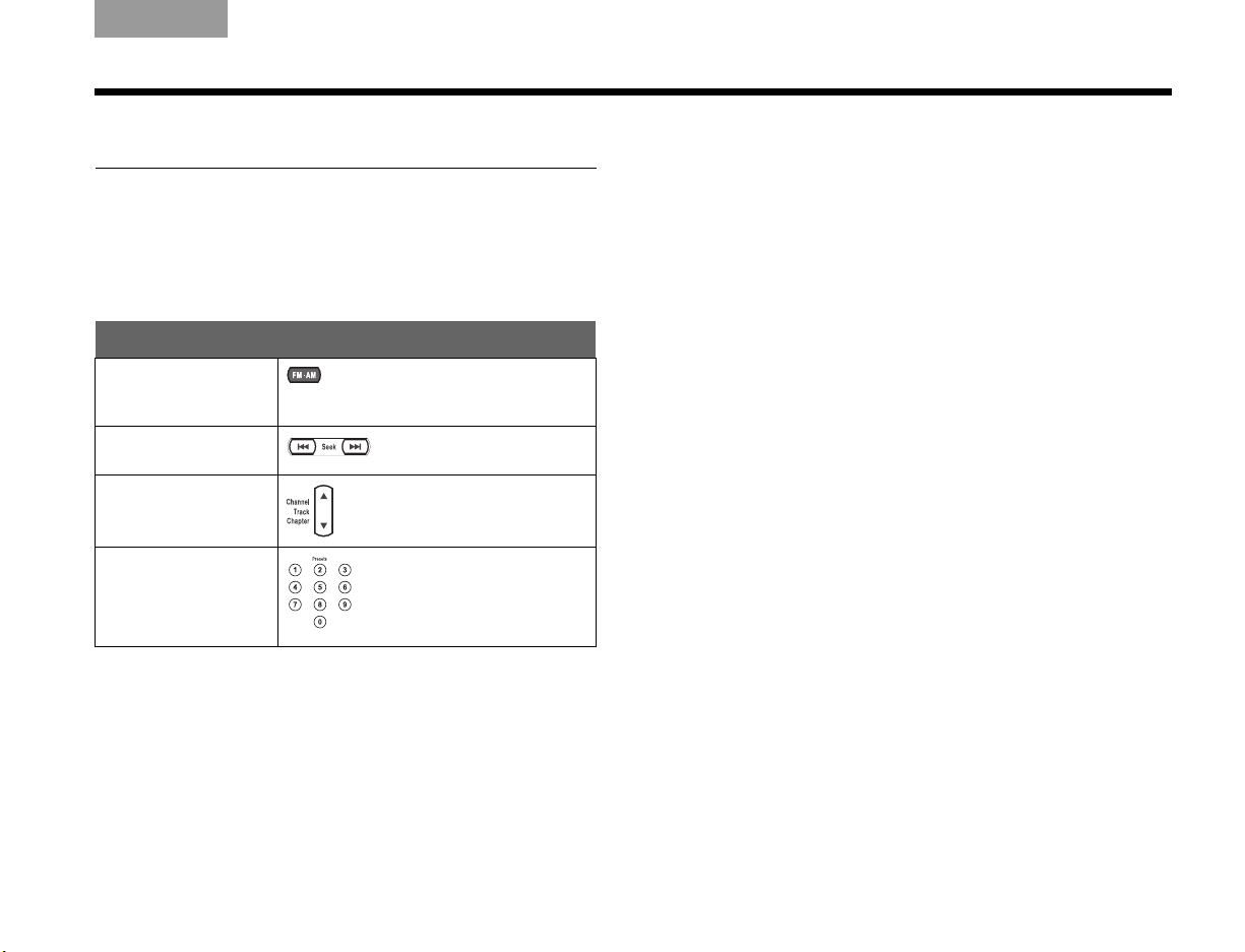
Using the radio
Press FM•AM to select the radio tuner. This turns on
the system if it was off and tunes to the FM or AM
station last selected.
To change stations
In order to: Press:
Change to FM•AM
from another
source...
Seek the next strong
station…
Manually tune
to a station…
Select a preset
station…
(if presets are set up)
Press again to switch
frequencies.
up or down
Using radio station presets
You can establish presets for up to 20 FM and 20 AM
stations and use them to find a favorite station quickly.
To set up a preset:
1. Tune to the preferred station.
2. Use one of these methods to give the station:
• A specific preset number: Press and hold the
remote control button for that number until the
display indicates it is set.
For a number from 10 to 20, press the first
number, then press and hold the second number.
Using a specific preset number for a station
overrides any other station previously assigned to
that number.
• The next available preset number: Press Enter
on the media center controls.
The assigned preset number appears on the
media center display as P#.
To remove a preset:
1. Tune to the preset number you want to remove.
2. On the remote control, press and hold the number
0 button until the media center display indicates it
has been removed.
Or press Erase on the media center control panel.
55
Page 60
USING THE VARIOUS SOURCES
USING THE VARIOUS SOURCES
EnglishTAB 6TAB 8 TAB 7 TAB 3TAB 5 TAB 2TAB 4
Using your TV, cable, satellite, DVR, or VCR
You can use the LIFESTYLE® remote control to operate
your other devices if the remote is set for each device.
If not, refer to “Making it a universal remote” on
page 41.
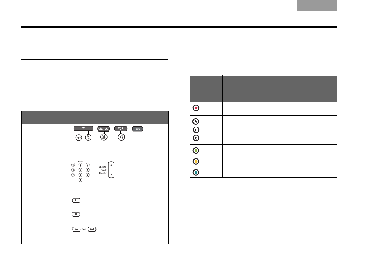
To control play
In order to: Press:
Select the
connected source...
Change TV,
cable, or satellite
channels...
Skip ahead or back
on your DVR or
VCR...
Pause play of your
DVR or VCR…
Stop play of your
DVR or VCR…
Search backward or
forward on your
DVR or VCR…
Use the On/Off button for TV, CBL•SAT, and
VCR to turn on the respective device.
Press again to resume play.
Press again to reset the recording to
begin.
Press again to move faster.
Recording and selecting from lists
Depending on where you purchased your system, the
remote control is designed for use either in the U.S. or
in other countries. Buttons at the bottom of your
remote are either colored or lettered accordingly.
On ly i n U.S. fo r DVR ,
VCR, cable, or satellite
Press:
Red Begin DVR or VCR
Green
Yellow
Blue
To:
recording
Select the respective
letter from a cable or
satellite on-screen list
Only in other countries for
Teletext, cable, or satellite
To:
Select the screen
content labeled red
Select content in the
respective color
56
Page 61

Italiano SvenskaDeutsch NederlandsEnglish FrançaisEspañol
MAKING LONG- OR SHORT-TERM ADJUSTMENTS
Changing system and source settings
There are two types of adjustments you can make:
System properties and Source settings.
Long-term system adjustments
Your system setup or preferences can require a onetime adjustment. For example:
• If the language you see on-screen is not the language
you speak, you have eight other choices. (See
“Changing the on-screen language” on page 58.)
• If an optical cable from your AUX or VCR device is
connected to the media center, you need to set the
Optical option in the System menu.
How to begin:
By pressing the System button, you can see the
System menu on screen, as shown on page 58.
To see all of your choices in the System menu, see
“Other system options” on page 59.
Important Note: Any changes that you make to System
properties are temporary until you turn off the system.
Unplugging the system or losing power erases your
unsaved changes.
Short-term source settings
You can change some settings temporarily while you
watch a video or listen to music. Your choices vary with
the source (CD or DVD, cable/satellite, VCR, or AUX)
that is playing.
For example:
• While watching a program or movie, you can adjust
for any delay between on-screen sound and action.
This is useful if you hear words before you see the
lips move when a character speaks, for example.
(See “Adjusting the audio timing” on page 61.)
• You can set the center speaker to play a little louder
while you watch a favorite DVD.
How to begin:
By pressing the Settings button while the system
plays, you can see settings for the source that is in use,
as shown on page 61.
For a list of your other options, see “Settings options”
on page 62.
Important Note: Many of the changes you make for a
source are temporary and revert to the original (default)
settings when you change sources or turn off the
system.
57
Page 62
MAKING LONG- OR SHORT-TERM ADJUSTMENTS
select
navigate
Media Center
Display Brightness: 4
Display Language: English
Optical Source: CBL•SAT
Digital Audio Output: Original
Tuner Spacing: US
Restore Settings: No
The media center supports several languages.
ItalianoSvenska DeutschNederlands EnglishFrançais Español
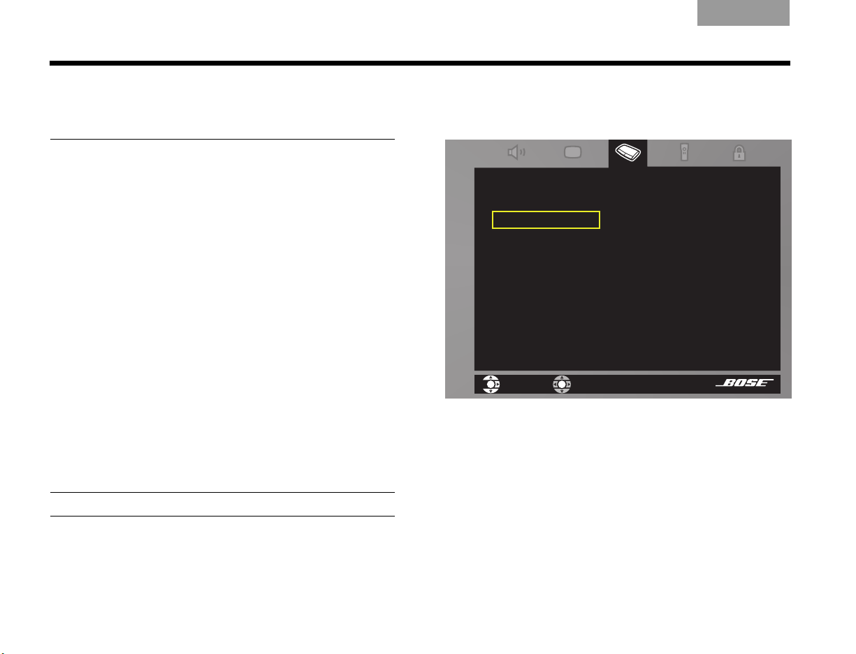
Changing the on-screen language
This is one example of making a System change.
1. Turn on your TV and your LIFESTYLE
2. Press the System button on your LIFESTYLE
remote.
The System menu appears on your TV screen. If it
does not, you need to change the Video Input on
your TV. Use one of these methods:
• Press the TV Input button on your LIFESTYLE
remote.
• Press the Input selection button on your TV
remote.
• Use the TV features menu to change inputs.
3. To get into the System menu, move right to reach
the Media Center icon.
A list of properties for this feature appears on the
menu screen.
Note: Entering the System menu pauses the DVD player.
®
system.
®
®
4. Press Enter to move into the menu, and use the
down arrow on the remote to move down to
Display Language.
5. Press the right arrow to move into the options and
move up or down to select the language you want
to see.
6. Press ENTER to make this selection.
7. Press Exit on the remote to dismiss the system
menu.
58
Page 63
Italiano SvenskaDeutsch NederlandsEnglish FrançaisEspañol
MAKING LONG- OR SHORT-TERM ADJUSTMENTS
Other system options
You can adjust these system properties, using the System menu, as needed.
Audio*
• Bass Compensation: Low-frequency reproduction, set to Normal (0), can vary from -9 to +14.
• Treble Compensation: High-frequency reproduction, set to Normal (0), can vary from -9 to +14.
• Audio Processing: Automatic can be changed to User Adjustable, which adds to your options in the Settings
list.
• Input Levels: Analog or Digital Input from TV, VCR, CBL•SAT, or AUX, set to Normal (0), can vary from -6 to +6.
Allows you to set your device volume levels to be even with internal source volumes.
®
• ADAPTiQ
: Set to Off (or On if ADAPTiQ audio calibration has been run). To override ADAPTiQ effects, choose
Erase.
• Expansion Protocol: Not for use unless it is indicated by a Bose technician (and used with legacy Bose•
products).
• CBL•SAT/VCR Audio: Can be set for TV stereo instead of 5.1 reproduction.
*Listening to an audio source while you make the adjustments above can be useful in fine-tuning your selections.
Video
• TV Power: Manual TV On/Off can be changed to Automatic. For a TV connected by SCART, the choice is
EURO.
• TV Power Status: Indicator of TV sensor detection after TV Power is set to Automatic. Otherwise, this is not
adjustable.
• Widescreen TV: Can change from a normal screen (4:3) to a widescreen (16:9) format.
• Widescreen DVDs: Can change from the original DVD format to one for a normal screen (4:3) – applies to
some discs only.
• Video Connector: Can change to reflect the type of video connector (Component or HDMI) is in use.
• TV Video Format: Can change from the standard monitor setting to the setting for a multiple format monitor.
• Video Black Level: The intensity of black on screen can be darkened (unless HDMI or Component video
connects the TV).
Video continues on the next page.
59
Page 64

MAKING LONG- OR SHORT-TERM ADJUSTMENTS
ItalianoSvenska DeutschNederlands EnglishFrançais Español
Video
Media
Center
Remote
Control
DVD
Lock
• Progressive Scan: Not applicable for systems that use the VS-2 video enhancer.
• Video Resolution: Allows for the resolution setting to be changed while watching a video source.
• Persistent Video: Can be set so the TV image from a video source remains on screen when an audio source is
selected.
• Settings on TV: Can restrict the video Settings list to appear on the media center display only (not on the TV).
• Display Brightness: Can change from bright (4) to darker (1-3).
• Display Language: Can change from English to one of 8 other languages.
• Optical Source: Can change from None to optical audio for TV, VCR, CBL•SAT, or AUX.
• Digital Audio Output: Can change to PCM (Pulse Code Modulation) to increase compatibility with a
connected digital audio source.
• Tuner Spacing: Can change from one standard station spacing for AM and FM to a different regional standard.
• TV Brand and Code plus Device, Brand, and Code for CBL
•
SAT, VCR, and AUX: your choices here allow
the remote to control each device.
• TV Control: Can choose to have the AUX, VCR, or CBL• SAT device (instead of your TV) respond to the TV
source button.
• Remote Version: Can change the function of some remote buttons to control either Teletext or Record
operations.
• IR Control: Can change to allow (Teach) another remote to control the system using IR commands (On).
• Create, Confirm, Enter, and Change Password: Can be set for restricting the use of some videos. For details,
refer to “Setting DVD Parental Control” on page 67.
• Lock Disc: Can be used to prevent unauthorized viewing of unrated or rated discs. Discs rated above the
number you choose are restricted.
60
Page 65

Italiano SvenskaDeutsch NederlandsEnglish FrançaisEspañol
Adjusts the audio to synchronize
with the video.
AUDIO DELAY: 0
SETTINGS
MAKING LONG- OR SHORT-TERM ADJUSTMENTS
Adjusting the audio timing
1. While you watch a video source (cable/satellite,
DVD, or VCR), press the Settings button on your
LIFESTYLE
2. The list of settings for this source appears on your
TV screen (below) and on your media center
display (right).
On-screen display of Settings list
®
remote.
If it does not appear on screen, you need to
change the Video Input on your TV. Use one of
these methods:
• Press the TV Input button on your LIFESTYLE
®
remote.
• Press the Input selection button on your TV
remote.
3. Press the down arrow to move to the Audio Delay
option and the right arrow to see your options.
Media center display of Settings
4. Move up to delay the audio (by 1 to 8 milliseconds)
and press ENTER to make your selection.
5. Notice the on-screen effect of this change, which
can be very subtle.
If further adjustment is needed, press the Settings
button and repeat the process.
6. Press Exit to leave the System menu.
61
Page 66

MAKING LONG- OR SHORT-TERM ADJUSTMENTS
ItalianoSvenska DeutschNederlands EnglishFrançais Español
Settings options
When you press the Settings button while a specific
source (like CD) plays, the setting options appear on
screen and on the media center display. Some, but not
all, of the following options are available for the
particular source.
Number of Speakers Playing
You may choose from 2, 3, 5, Audio 5, or Video
5, depending on the source playing.
Surround Volume
You can adjust the rear speaker volume relative
to the three front speakers.
Center Speaker Volume
You can adjust this volume relative to the four
other speakers.
Sleep Timer
You can set the time (up to 90 minutes) for the
system to turn off.
RDS for FM only (outside the USA)
You can dismiss the media center display of
information.
Output Mode for FM only
You can set this for Stereo-only or Mono-only
play.
Audio Track
You can change DTS to the Dolby Digital audio
format for movies or CDs.
Audio Delay
You can synchronize the audio-to-video timing.
Your choices are 0 and 2-8, in 30-millisecond
increments.
Movie EQ
You can turn this on to adjust the bass-to-treble
ratio for a movie soundtrack.
Range Compression
You can set this to reduce normal volume
ranges in a movie soundtrack, to prevent
disturbing others.
62
Page 67

Italiano SvenskaDeutsch NederlandsEnglish FrançaisEspañol
MAKING LONG- OR SHORT-TERM ADJUSTMENTS
Mono Decoding
You set this to off so Videostage
®
5 decoding
does not send mono movie audio to all five
speakers.
Video Resolution
You can choose among the screen resolutions
your TV provides.
SD Progressive Scan
You can change from standard interlaced video
to progressive scan if your TV connection is
Component.
Image View
You can change the proportions of the onscreen image by adding gray bars to each side
or stretching the image to fit. Zoom is not
available.
Subtitle Language
You can choose a different language for
subtitles, as provided on the DVD.
Time
You can advance or reverse the movie by using
the remote control number buttons to set a new
time.
Title
You can advance or reverse the movie by
pressing the number buttons for a different title.
Chapter
You can advance or reverse the movie by
pressing the number button for a different
chapter.
Camera Angle
You can select the viewing angle for a scene on
some DVDs.
A/B Repeat
You can select a DVD segment (a, b) and set it
to repeat. For more details, see “To repeat a
segment of the DVD” on page 67.
63
Page 68

REFERENCE
What you need to use:
Your TV
(a European model only)
Media center
SCART adapter
VS-2 video enhancer
S-Video plug
Composite plug
Connections: For TVs requiring SCART (in Europe, only)
ItalianoSvenska DeutschNederlands EnglishFrançais Español
1. Locate the SCART connector on the rear of your TV
and plug the large end of the SCART adapter into
this connector.
64
2. Identify the two video plugs, S-Video and
composite, on one end of the adapter.
Page 69

Italiano SvenskaDeutsch NederlandsEnglish FrançaisEspañol
S-Video
Out
Composit
Out
(cont.) For TVs requiring SCART (in Europe, only)
REFERENCE
3. Locate the S-Video and composite Video Out
connectors on the VS-2 connection pannel.
4. Insert the video cable plugs on the SCART adapter
into the matching Video Out connectors on the
VS-2.
5. On the same end of the SCART adapter, identify
the plug for the TV sensor.
6. On the back of the media center, locate the TV
sensor connector.
65
Page 70

REFERENCE
TV
7
(cont.) For TVs requiring SCART (in Europe, only)
ItalianoSvenska DeutschNederlands EnglishFrançais Español
7. Insert the TV sensor plug into the TV Sensor
connector on the media center.
8. Locate the Audio IN connectors that are labeled TV
on the back of the media center.
9. Insert the red and white audio plugs on the SCART
adapter into these connectors.
Be sure to match the colors on the plugs to the
connector colors: red to red and white to white.
Note: When this SCART connection to the TV is
completed, see on “Connecting another device
(cable or satellite box, VCR, or DVR)” on page 29 to
continue with connections.
66
Page 71

Italiano SvenskaDeutsch NederlandsEnglish FrançaisEspañol
REFERENCE
More about DVD play
Some additional features apply to DVDs only.
To repeat a segment of the DVD
To replay a segment of the DVD more than once, you
can choose the AB repeat option in the DVD Settings
menu, as follows:
1. Press Settings on the remote and move
down the list of options until you reach the
AB icon.
2. Press ENTER to activate this selection. The letters
a and b appear in a highlighted box to the right of
the menu list.
3. Press ENTER at a point in the DVD where you want
to begin or end the segment.
The a changes to A, confirming your action.
4. Move backward or forward to the next point that
defines the segment.
5. Press ENTER.
The b changes to B to confirm that you have
defined the segment.
The repeat of that segment begins.
Setting DVD Parental Control
You can password-protect some DVDs that are not
appropriate for other family members.
Choosing a password
1. Turn on your TV and your LIFESTYLE
Be sure to select the same TV Video Input that you
use to watch a DVD.
2. Press the System button on the remote control.
The System menu appears on screen.
3. Press the right arrow button to move to the DVD
Lock icon .
4. Press ENTER to select that feature.
5. Use the number buttons to create your four-digit
password.
®
system.
Repeat continues until you press the ENTER or Stop
button.
67
Page 72

REFERENCE
ItalianoSvenska DeutschNederlands EnglishFrançais Español
Setting a restriction level
1. Refer to the chart of ratings defined by the Motion
Picture Association of America (MPAA) to choose a
Parental Control Setting.
The numbers above the setting you select will be
restricted.
Parental Control
Setting
8None
7 NC-17 Adult audiences
6 R Mature audiences
5 Mature teenagers
4 PG-13 Teenage audiences
3 PG Mature young audiences
2 Most audiences
1GGeneral
MPAA
Rating
Audience
Restriction
2. In the System menu, select DVD Lock and enter
your password.
3. Use the arrow buttons to reach Lock UnRated
Discs and select Yes.
4. Move down to Lock Discs Rated Above and move
right to the numbers.
5. Press the up or down arrow button to select your
setting number.
Any numbers above this selection will be restricted
by password protection.
6. Press ENTER to save this setting and Exit to move
out of the System menu.
68
Page 73

Italiano SvenskaDeutsch NederlandsEnglish FrançaisEspañol
REFERENCE
Maintaining the system
Taking care of this system requires very little effort.
Protecting and keeping it clean
Follow the guidelines below when cleaning the
surfaces.
• Do not use any solvents, chemicals, or cleaning
solutions containing alcohol, ammonia, or abrasives.
• Do not use any sprays near the system.
Cleaning the media center
Use only a soft, dry cloth to clean the outside of the
media center.
Cleaning the speakers
Clean the surface of your speakers with a soft, damp
cloth. You can use an ammonia-free window cleaner on
a soft cloth to maintain the finish.
The speaker grille panels require no special care,
although you may vacuum them carefully, if necessary.
Checking your remote control response
If your system does not respond when you press a
button on the remote:
• There may be “dead spots” in the building where
remote control signals are not effective.
If this happens, move the remote a foot or two and try
again.
If this does not help, move the media center a few
feet to see if a new location provides better
response.
• It could be time to change the batteries.
If the batteries are not dead and your efforts to avoid
dead spots are in vain, you may need an antenna
extender. To contact Bose for more information, or to
order the extender, refer to the address list included in
the carton.
69
Page 74
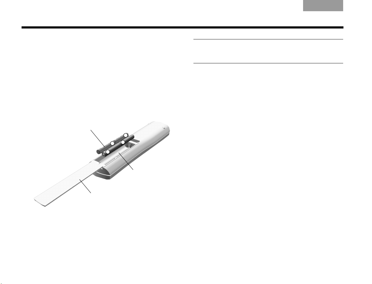
REFERENCE
+
+
+
+
Battery
compartment
cover
Battery
compartment
AAA batteries (4)
ItalianoSvenska DeutschNederlands EnglishFrançais Español
Replacing the remote control batteries
Replace all four batteries when the remote control
stops operating or its range seems reduced. Alkaline
batteries are recommended.
1. Slide open the battery compartment on the back of
the remote.
2. Insert four AAA or IEC-LR3 1.5V batteries, or the
equivalent, as shown. Match the + and – symbols
on the batteries with the + and – markings inside
the compartment.
3. Slide the battery compartment cover back into
place.
Note: For information on using the small switches inside
the battery compartment, see “Changing remote control
switch settings” on page 71.
70
Page 75

Italiano SvenskaDeutsch NederlandsEnglish FrançaisEspañol
HOUSE CODE:
Switches 1-4 down = 0 0 0 0
(current house code)
NEW HOUSE CODE:
(Switch 1 up, 2 down, 3 up, and 4 down = 1 0 1 0
(new house code)
REFERENCE
Changing remote control switch settings
Each LIFESTYLE® remote control uses a house code
that corresponds to the house code set in the media
center, enabling the two to communicate.
If another LIFESTYLE
with your system, you can easily set a new house code
in your media center and in the remote control(s) by
following these steps.
Changing the remote control setting
1. Open the remote control battery cover and locate
the miniature switches (see page 72).
2. Move one or more of switches 1, 2, 3, or 4 in the
opposite direction from its current setting. Use a
paper clip, ball point pen, or similar object.
Note: DO NOT change any other switch settings. Moving
other switches may disable your remote control.
3. Replace the battery cover.
4. Follow the instructions for “Changing the media
center setting.”
If you have additional remote controls, simply follow
steps 1-3 above to change the switches to match the
switches in the first remote control.
®
system nearby creates a conflict
Changing the media center
1. Lift the media center door and press the
media center All Off button.
2. Press and hold the media center Enter button.
Your current house code appears in the media center display window. The four rectangles represent
the positions of switches 1 through 4:
3. While holding the Enter button, press any button on
the remote control. The media center displays the
new house code, which confirms recognition of the
new code:
4. Release the Enter button. The system remains off.
Note: To verify your system’s house code, press Enter
while the system is off. The settings for switches 1-4
appear on the media center display.
71
Page 76

REFERENCE
123456789
Switches (1-4)
as set at the factory:
all switches down.
To use a second remote in the main room (Room A), be
sure the switch settings match those of your main room
remote.
In another room, where a Bose
®
link-compatible product
is set up, you need a Bose link remote control.
On this additional remote:
• Make sure switches 1-4 are set to match the settings in
your main room remote.
• Make sure switches 5-9 do not match the settings for
Room A.
The codes for additional rooms are provided in the
owner’s guide included with the Bose link remote control.
• Switches 5-9 are set at the factory for control in the
main room where your system is set up, Room A.
• Switch 5 determines which “audio stream” (of two) you
hear. This switch, set in the down position, enables the
remote to control Stream 1.
• Switches 6-9, also in the down position, provide full
system control for the remote in the main room.
• Further information on audio streams is provided in
“Setting up other rooms with sound” on page 73.
Other switches
Settings for additional remote controls
ItalianoSvenska DeutschNederlands EnglishFrançais Español
123456789
72
Page 77

Italiano SvenskaDeutsch NederlandsEnglish FrançaisEspañol
REFERENCE
Setting up other rooms with sound
Your LIFESTYLE® system is capable of supplying up to
14 rooms with Bose
throughout your living space.
It can even play the audio from two different sound
sources (such as CD, FM/AM tuner, VCR, or AUX) on
separate streams in these different rooms.
So, when music is playing in the main room, listeners in
other rooms can enjoy that same music, or an entirely
different audio selection, for true independence.
Bose link-compatible products make it easy
As an option to provide sound throughout your home
(or outdoors), the Bose link network connects all of the
pieces and offers a variety of Bose products of
consistent quality for use in other rooms.
For ease of installation, you can use the Bose link AL8
homewide wireless audio link to work with a variety of
our products, like the 3•2•1
you have another TV.
®
quality sound – for music
®
system for rooms where
Other possibilities include:
• A LIFESTYLE
®
Homewide powered speaker system
in your den.
•A Wave
• The LIFESTYLE
®
music system in your bedroom.
®
RoomMate® powered speakers in
the kitchen.
• Free Space
®
51 environmental speakers (or any from
our variety of outdoor speakers) for the backyard.
To add a Bose link remote control in each of these
spaces, you can choose a PERSONAL
®
music center II.
For added control, it features an LCD screen so you
can see what is playing and what other play options
you can choose.
Each Bose link-compatible product includes detailed
instructions for adding it to your LIFESTYLE
®
DVD
home entertainment system.
For more information or to purchase additional
equipment, contact your local Bose dealer. Or, to reach
Bose directly, refer to the address list included in the
carton.
73
Page 78
REFERENCE
Troubleshooting
System issues What to do
ItalianoSvenska DeutschNederlands EnglishFrançais Español
System doesn’t turn on
System is on, but there is no
sound
System turns on by itself, or
behaves erratically
• Unplug the VS-2 power supply for 60 seconds, then reconnect it. This allows the unit to reset itself after
a power surge or power interruption.
• Make sure:
– The plug on one end of the AC power cord is securely inserted into the AC (mains) outlet and the other
end is connected to the power supply.
– The power supply cable is fully inserted into the DC POWER In connector at one end of the VS-2.
– The VS-2 cable is securely attached to the VS-2 DC POWER Out and MEDIA CENTER connectors.
– The plugs at the other end of the VS-2 cable are plugged into the proper connectors on the media
center.
• Refer to “Connecting the media center” on page 19 for detailed information.
• Be sure to press a source button (Stored, CD•DVD, AM•FM, TV, Cable, or AUX) on the LIFESTYLE®
remote control.
• Increase the volume.
• For CD or DVD play, be sure the disc is placed correctly, label-side up, in the disc tray.
• For AM or FM play, be sure the antennas are properly connected.
• Turn off the media center for 60 seconds, then on again, to restore communication between the media
center and the speakers.
• Make sure:
– The power cord is fully inserted into the AC Power connector on the Acoustimass
operating AC (mains) outlet.
– The audio input cable is firmly inserted into the AUDIO INPUT connector on the Acoustimass module
and the Main Speaker connector on the media center.
• For details, refer to “Connecting all of the speakers” on page 14.
• Change the remote control house code setting to prevent signals from conflicting with another nearby
LIFESTYLE
®
system. (Refer to “Changing remote control switch settings” on page 71.)
®
module and into an
74
Page 79
Italiano SvenskaDeutsch NederlandsEnglish FrançaisEspañol
System issues What to do
REFERENCE
Sound is distorted
No sound from center speaker
Center speaker is too loud
No sound from surround
speakers
Surround speakers are too
loud
• Make sure the volume setting for any devices connected to the media center is no more than 75% of
maximum.
• Make sure speaker cables are not damaged and the connections are secure.
• For details, refer to “Connecting all of the speakers” on page 14.
• Contact Bose
®
Customer Service to determine if and how other electrical components in the room may
be creating unwanted signals, and the possible remedies.
For contact information, refer to the address list included in the carton.
• Make sure the center speaker cable is connected at both ends.
• In the Settings list, check to be sure that 3 or 5 speakers are selected for play.
• In the Settings list, decrease the Center Channel volume setting.
• In the Settings list:
– Check to be sure 5 speakers are selected for play.
– Increase the Surround volume setting for the source being played.
• Make sure the video sound source is stereo- and surround-encoded, and the component used (TV, VCR,
DVR, etc.) is stereo.
Many scenes in a movie do not engage the rear (surround sound) speakers, which serve primarily to deliver special
effects. Such effects (during traffic or outdoor scenes, for example) help create a more true-to-life experience.
• In the Settings list, decrease the Surround volume setting for the source being played.
• Make sure the left and right surround speakers are connected to the rear speaker jacks.
• For details, refer to “Connecting all of the speakers” on page 14.
75
Page 80

REFERENCE
Remote issues What to do
ItalianoSvenska DeutschNederlands EnglishFrançais Español
Remote does not control your
TV, VCR, cable/satellite box, or
other external component
Remote behaves erratically or
does not work
If this occurs when a plasma
TV is on, see the issue below.
With a plasma-screen TV
turned on, the remote behaves
erratically
• Make sure correct codes are set. See “Setting the remote to control your TV and other devices” on
page 40.
• Make sure the front of the media center is not obstructed. The IR emitter that sends commands to your
external components is below the disc tray.
• If you still cannot control your external components successfully, you may need to connect the external
IR emitter, included with your system, to the IR EMITTER jack on the rear panel of the media center. See
“IR emitter cable as an option” in your Installation Guide.
• Check batteries and their polarity (+ and –).
• Make sure the VS-2/media center input and output cords are securely connected, uncoiled, and
extended to their full length.
• Make sure the VS-2 cable between the VS-2 and the media center is securely connected, uncoiled, and
straightened as much as possible.
• If you are using a plasma-screen TV, make sure the media center power source is as far away from the
TV as possible.
• Move the remote (or the media center) a few feet to avoid an area of “dead spots.”
• Make sure the remote control and media center house codes match.
• Contact Bose
®
Customer Service for assistance.
• Momentarily disconnect the video cable (composite, S-Video, or component) and see if remote performance improves.
• If performance improves, the problem may be remedied by obtaining “ferrite chokes” and placing them
on the cable to draw away the interference. To purchase the chokes, contact Bose Customer Service for
assistance.
76
Page 81

TV issues What to do
No video on the TV screen,
though the TV audio
functions
No sound from TV
TV screen goes dark or the
image flips repeatedly after a
change is made to a Video feature in System settings
TV turns on and off unexpectedly
Parental Control forgotten
or does not work
Italiano SvenskaDeutsch NederlandsEnglish FrançaisEspañol
REFERENCE
• Check the TV video input selection. Make sure it is correct for the video source.
• Check the connections.
• Make sure component is turned on.
• Refer to the component owner’s manual.
• In the System menu, make sure the Video format is set to NTSC (U.S. standard) or PAL
(European standard).
• In the Settings list, make sure the SD Progressive Scan setting is off, unless you have used a
component video connection and progressive scan is a feature of the TV.
• Reposition the TV on/off sensor on the back of your TV. Or check the SCART connector if you use one.
• Verify that the TV on/off sensor is working properly by choosing
System menu.
• In the DVD feature of the System menu, use the number buttons on the remote to enter 2673 in the
Password blanks. This provides temporary access and allows you to change the password.
TV Power Status
under Video in the
77
Page 82

REFERENCE
Source Issues What to do
The disc does not play or plays
intermittently
No sound from a component
connected to the VCR or AUX
Audio In connector on the
media center
Radio does not work or the
sound is distorted
FM sound is noisy when 3 or 5
speakers play
ItalianoSvenska DeutschNederlands EnglishFrançais Español
• After pressing the CD/DVD button, wait a few seconds before pressing Play.
• Make sure the disc is properly inserted (label side up).
• Eject the disc and try loading it again.
• Check the disc for scratches, fingerprints, smears, or dirt. See “Protecting and keeping it clean” on
page 69.
• Try another CD. The CD may be defective or not compatible. See “Discs that are system compatible” on
page 54.
• Make sure component is plugged in and turned on.
• Check the connections.
• Refer to “Connecting another device (cable or satellite box, VCR, or DVR)” on page 29.
• Refer to the component owner’s manual.
• Select another station. You may be in an area of weak signal coverage for some stations.
• Make sure antennas are connected properly.
• Move the ends of the FM antenna to improve reception.
• Make sure the AM antenna is in an upright position.
• Move AM antenna at least 20 inches (50 cm) from the media center.
• Move antennas farther from media center, TV, or other electronic equipment.
• Refer to “Connecting the AM and FM antennas” on page 37.
• Weak FM stations will produce static in the surround speakers. Select the 2-speaker mode in the
Settings menu to minimize noise. See “Changing system and source settings” on page 57.
Storing issues What to do
Storing music tracks takes
much longer than expected
78
• Remove the disc and check for scratches, which may slow the process or make it impossible to store all
tracks.
• Or, if the CD needs cleaning, refer to “Cleaning discs” on page 53.
Page 83

Italiano SvenskaDeutsch NederlandsEnglish FrançaisEspañol
REFERENCE
Contacting Bose
For additional help in solving problems, contact Bose®
Customer Service. Refer to the address sheet included
in the carton.
Limited Warranty
Your LIFESTYLE® DVD home entertainment system is
covered by a limited transferable warranty. Details of
the limited warranty are provided on the product
registration cart that is included in the carton. Please
refer to the card for instructions on how to register.
Failure to register will not affect your limited warranty
rights.
What you must do to obtain Limited Warranty Service
Return the product, with proof of purchase from an
authorized Bose dealer, using the following procedures:
1. Visit http://global.Bose.com or contact your local
authorized Bose dealer to identify the location of
the nearest authorized Bose service facility;
2. Contact the authorized service facility for specific
return and shipping instructions;
3. Label and ship the product, freight prepaid, to the
address provided by the authorized service facility;
and
4. Place any necessary return authorization number
prominently on the outside of the carton. Cartons
not bearing a return authorization number, where
required, will be refused.
79
Page 84

REFERENCE
ItalianoSvenska DeutschNederlands EnglishFrançais Español
Technical information
Media center power pack power rating
USA/Canada: 120V 0.55A 50/60 Hz 30VDC 1.1A
or 33VDC 1.1A
International: 220-240V 0.30A 50/60 Hz 30VDC
1.1A or 33VDC 1.1A
Dual voltage: 115/230V 0.55A 50/60 Hz 30VDC
1.1A or 33VDC 1.1A
Speaker system power rating
USA/Canada: 100-120V 50/60 Hz 350W
International: 220-240V 50/60 Hz 350W
Dual voltage: 100-120/220-240V 50/60 Hz 350W
VS-2 power rating
9 W
Frequency
USA/Canada: 27.145 MHz
EU/Other: 40.685 MHz
RF field strength
<80dBµV/m@ 3 meters (average)
Media center inputs
AUX: 2Vrms, maximum
CBL•SAT: 2Vrms, maximum
VCR: 2Vrms, maximum
TV: 2Vrms, maximum
DIGITAL: SPDIF (1 each for TV, VCR, TAPE, and AUX)
COMPOSITE VIDEO: NTSC or PAL format 1V
sync 75Ω
S-VIDEO: Luminance 1V
COMPONENT VIDEO: NTSC or PAL 1V
on Y
OPTICAL INPUT: SPDIF digital, mapped to input
FM ANTENNA: 75Ω
AM ANTENNA: 12µH
TV SENSOR: Scan frequency sensing
Chrominance 0.3V
p-p
p-p
with
p-p
p-p
with sync
80
Page 85

Italiano SvenskaDeutsch NederlandsEnglish FrançaisEspañol
REFERENCE
Media center outputs
SPEAKERS, MAIN and BOSE
®
LINK: Variable audio,
user selectable
AUDIO OUT L and R, fixed audio, 2 Vrms maximum
DIGITAL AUDIO OUT: SPDIF
OPTICAL OUTPUT: SPDIF, –15 to –21 dbm
COMPOSITE VIDEO: NTSC or PAL 1V
with sync
p-p
75Ω
S-VIDEO: Luminance 1V
COMPONENT VIDEO: NTSC or PAL 1V
Chrominance 0.3V
p-p
with sync
p-p
p-p
on Y
VS-2 inputs
(2) HDMI (CBL•SAT and VCR)
(3) Component video
(3) S-Video
(3) Composite video
VS-2 output
HDMI
Component video
S-Video
Composite video
Remote control range
65 ft (20 m)
81
Page 86

REFERENCE
ItalianoSvenska DeutschNederlands EnglishFrançais Español
END USER LICENSE AGREEMENT
IMPORTANT: READ CAREFULLY: This End User License Agreement
(“EULA”) is a legal agreement between you, the End User (“End
User” or “You”), and Bose Corporation (“Bose”) governing your use
of the technology and software and data and data content belonging
to Bose, its vendors and licensors (“Technology”), that is contained
in this audio/video device (“System”). By tearing open the protective
wrapping on this System, you are agreeing to be bound by the terms
of this EULA. In the event you disagree with any of the terms
contained herein, DO NOT UNWRAP THIS SYSTEM. Return the
sealed System to the Bose Corporation for a full refund.
Copyright laws and international copyright treaties, as well as other
intellectual property laws and treaties protect the Technology
contained within this System. The Technology is being licensed, not
sold. This EULA grants you the right to use the Technology only on
this Bose System. You may NOT transfer, lend, distribute, prepare
derivative works, reverse engineer, de-compile, or disassemble the
Technology, except and only to the extent that applicable law
expressly permits such activity. You agree that you will use the
Technology and the System solely for your own personal noncommercial use.
The Technology contains software that allows You to obtain vendorsupplied music-related information, including name, artist, track,
and title information (“Data”). You may use Data only by means of
the intended End User functions of the Technology. You agree not to
assign, copy, transfer, or transmit such Data to any third party. YOU
AGREE NOT TO USE OR EXPLOIT DATA EXCEPT AS EXPRESSLY
PERMITTED HEREIN.
You agree that your non-exclusive license to use the Technology will
terminate if you violate these restrictions. If your license terminates,
you agree to cease any and all use of the Technology or Data. Bose,
its vendors, and licensors reserve all rights in the Technology,
including all ownership rights. You agree that the vendors and
licensors of Bose may enforce their rights under this Agreement
directly in their own name.
Bose warrants this System in accordance with the provisions of the
warranty card delivered with this System. EXCEPT AS EXPRESSLY
SET FORTH THEREIN, BOSE, ITS VENDORS, AND ITS LICENSORS
HEREBY DISCLAIM ALL WARRANTIES, EXPRESS, IMPLIED, AND
STATUTORY, IN CONNECTION WITH THE TECHNOLOGY,
INCLUDING WITHOUT LIMITATION, THE IMPLIED WARRANTIES
OF MERCHANTABILITY, NON-INFRINGEMENT OF THIRD PARTY
RIGHTS, AND FITNESS FOR A PARTICULAR PURPOSE. IN NO
EVENT WILL BOSE, ITS VENDORS, OR ITS LICENSORS BE LIABLE
FOR ANY INDIRECT, SPECIAL, INCIDENTAL, OR CONSEQUENTIAL
DAMAGES ARISING OUT OF THE USE OR INABILITY TO USE THE
TECHNOLOGY. IN NO EVENT SHALL BOSE BE LIABLE FOR ANY
DAMAGES.
None of the Technology shall be exported or re-exported in violation
of any export provisions of the United States or any other applicable
jurisdiction. Any attempt to sublicense, assign, or transfer any of the
rights, duties, or obligations hereunder shall be void. This Agreement
shall be governed by and interpreted under the laws of the
Commonwealth of Massachusetts, without regard to its conflicts of
law provisions.
YOU ACKNOWLEDGE THAT YOU HAVE READ AND UNDERSTAND
THIS AGREEMENT AND AGREE TO BE BOUND BY ITS TERMS.
YOU FURTHER AGREE THAT THIS AGREEMENT IS THE
COMPLETE AND EXCLUSIVE STATEMENT OF THE AGREEMENT
BETWEEN YOU AND BOSE AND SUPERCEDES ANY PROPOSAL
OR PRIOR AGREEMENT, ORAL OR WRITTEN, AND ANY OTHER
COMMUNICATIONS RELATING TO THE SUBJECT MATTER OF
THIS AGREEMENT.
Dolby and the double-D symbol are trademarks of Dolby Laboratories. Manufactured under
license from Dolby Laboratories. Confidential unpublished works. 1992-1997 Dolby
Laboratories. All rights reserved.
This product contains one or more programs protected under international and U.S.
copyright laws as unpublished works. They are confidential and proprietary to Dolby
Laboratories. Their reproduction or disclosure, in whole or in part, or the production of
derivative works therefrom without the express permission of Dolby Laboratories is
prohibited. Copyright 1992-1996 by Dolby Laboratories, Inc. All rights reserved.
82
Page 87

Italiano SvenskaDeutsch NederlandsEnglish FrançaisEspañol
Licenses
Manufactured under license under U.S. Patent #’s: 5,451,942; 5,956,674;
5,974,380; 5,978,762; 6,487,535 & other U.S. and worldwide patents
trademarks and the DTS logos and Symbol are trademarks of DTS, Inc. ©1996-2007 DTS,
Inc. All Rights Reserved.
MPEG Layer-3 audio compression technology licensed by Fraunhofer IIS and THOMSON
multimedia.
This product incorporates copyright protection technology that is protected by method
claims of certain U.S. patents and other intellectual property rights owned by Macrovision
Corporation and other rights owners. Use of this copyright protection technology must be
authorized by Macrovision Corporation, and is intended for home and other limited viewing
uses only unless otherwise authorized by Macrovision Corporation. Reverse-engineering or
disassembly is prohibited.
Consumers should note that not all high-definition television sets are fully compatible with this
product and may cause artifacts to be displayed in the picture. In case of 525 or 625
progressive scan picture problems, it is recommended that the user switch the connection to
the “standard definition” output. If there are questions regarding our TV set compatibility with
this model 525p and 625p DVD player, please contact our customer service center.
Designed with UEI Technology™ Under License from Universal Electronics Inc. © UEI 2000-
2002.
This product incorporates copyright-protected technology and other intellectual property
rights owned by Cirrus Logic, Inc., and subject to the copyright-protection of the U.S., as
well as other licensing restrictions and protections. Use of this copyright protected
technology is limited solely to use with the Cirrus Logic integrated circuits incorporated in this
product. Reverse-engineering or disassembly is prohibited.
#5,987,525; #6,061,680; #6,154,773; #6,161,132; #6,230,192; #6,230,207; #6,240,459;
#6,330,593, and other patents issued or pending.
Gracenote and CDDB are registered trademarks of Gracenote. The Gracenote logo and
logotype, the Gracenote logo, CDDB logo and logotype and the “Powered by Gracenote”
logo are trademarks of Gracenote.
issued & pending. DTS and DTS Digital Surround are registered
Music recognition technology and related data are provided by Gracenote
and the Gracenote CDDB
industry standard in music recognition technology and related content
delivery. For more information visit www.gracenote.com.
CD and music-related data from Gracenote, Inc., © 2000-2003 Gracenote.
Gracenote CDDB
product and service may practice one or more of the following U.S. Patents
Data provided by All Music Guide © 2004 AEC One Stop Group,
Inc. All Music Guide is a registered trademark of AEC One Stop
Group, Inc.
®
music recognition service. Gracenote is the
®
Client Software, copyright 2000-2003 Gracenote. This
REFERENCE
®
83
Page 88

INFORMACIÓN DE SEGURIDAD
EnglishTAB 6TAB 8 TAB 7 TAB 3TAB 5 EspañolTAB 4
Lea esta guía del usuario
Dedique el tiempo que sea necesario para seguir atentamente
las instrucciones de esta guía, que le ayudará a configurar y
utilizar correctamente el sistema y a disfrutar de todas sus
funciones avanzadas. Guarde esta guía para utilizarla como
material de referencia en el futuro.
ADVERTENCIAS:
El símbolo de relámpago con una flecha dentro de un
triángulo equilátero indica al usuario que la caja del
sistema puede contener una tensión sin aislar de
magnitud suficiente para constituir un riesgo de
descarga eléctrica.
El signo de exclamación dentro de un triángulo
equilátero avisa al usuario de que existen instrucciones
de operación y mantenimiento importantes en esta guía.
• Con el fin de reducir el riesgo de descargas eléctricas, no
exponga el producto a la lluvia o la humedad.
• No exponga este aparato a salpicaduras o goteo.
No coloque encima o cerca del aparato objetos que
contengan líquidos, como jarrones. Al igual que con
cualquier producto electrónico, evite que se derramen
líquidos en los componentes del sistema, ya que podrían
producirse fallos o fuego.
• No coloque sobre el aparato o cerca de éste llamas vivas,
por ejemplo, velas.
PRECAUCIONES:
• El uso de controles o ajustes o la realización de
procedimientos distintos de los especificados en este
documento pueden ocasionar la exposición a radiaciones
peligrosas. Sólo técnicos convenientemente cualificados
deberán ajustar y reparar el reproductor de discos
compactos.
• No realice modificaciones en el sistema o los accesorios.
Las alteraciones no autorizadas pueden comprometer
aspectos de seguridad, cumplimiento normativo y
rendimiento del sistema, y pueden anular la garantía.
Información de seguridad adicional
Consulte las instrucciones adicionales de la hoja
de seguridad importante
envío.
que se incluyen en el embalaje de
Información
Nota:
• Si se utiliza el enchufe de red o el conector del aparato
como dispositivo de desconexión, deberá poder accionarse
fácilmente.
• Este producto debe utilizarse en espacios interiores.
No está diseñado ni se ha probado para uso al aire libre o
en embarcaciones.
• Este producto sólo se debe utilizar con la fuente de
alimentación proporcionada.
ii
Page 89

TAB 5TAB 4TAB 6TAB 8TAB 7English TAB 3Español
Producto láser clase 1
Este reproductor de CD/DVD está
clasificado como PRODUCTO
LÁSER CLASE 1 de acuerdo con la
norma EN 60825-1:1994+A1+A2,
CLASS 1 LASER PRODUCT
KLASSE 1 LASER PRODUKT
LUOKAN 1 LASER LAITE
KLASS 1 LASER APPARAT
IEC60825-1:1993+A1+A2.
Emisiones de clase B
• Este aparato digital de Clase B cumple todos los requisitos
de las leyes de Canadá sobre equipos que causan
interferencias (sólo Canadá).
• El dispositivo de comunicaciones por radio que incorpora
este aparato cumple todos los requisitos de la norma
canadiense RSS-310 (sólo Canadá).
Este producto cumple la Directiva sobre compatibilidad
electromagnética (EMC) 2004/108/EC y la Directiva sobre
límites de tensión 2006/95/EC. El mando a distancia cumple la
Directiva RTTE 99/5/EC. Consulte la declaración de
conformidad completa en.
www.
Bose
.com/static/compliance/index.html.
Pilas
Deseche correctamente las pilas usadas, siguiendo las
disposiciones locales. No las queme.
Registro del producto
Al registrar su producto tendrá derecho a recibir
actualizaciones gratuitas del sistema para mantener un
funcionamiento óptimo del mismo. Asimismo, nos permite
enviarle información sobre nuevos productos y ofertas
especiales de Bose.
Siga las instrucciones de la tarjeta de registro del producto
para registrarse por correo electrónico, Internet o por teléfono.
En caso de no registrarse, la garantía limitada no se verá
afectada.
Para conservar como referencia
Bose le recomienda anotar la información sobre el modelo del
sistema aquí y los números de serie aquí y en la tarjeta de
registro del producto.
Hay números de serie impresos en la parte inferior del centro
de medios y el VS-2, y en el panel de conexión del módulo
Acoustimass
Nombre y número de modelo del sistema (en la caja):
Mando a distancia del
sistema LIFESTYLE®________________________ Serie #______
Números de serie:
Nº. de serie del centro de medios: __________________________
Código de barras VS-2:____________________________________
N/S del módulo Acoustimass®: _____________________________
Nombre del distribuidor: _________________________________
Teléfono del distribuidor:_________________________________
Fecha de compra: ________________________________________
Le recomendamos que conserve el recibo de compra y una
copia de la tarjeta de registro del producto junto con esta guía.
®
.
iii
Page 90

CONTENIDO
EnglishTAB 6TAB 8 TAB 7 TAB 3TAB 5 EspañolTAB 4
INTRODUCCIÓN 2
Bienvenido . . . . . . . . . . . . . . . . . . . . . . . . . . . . . . 2
Simplificar la configuración . . . . . . . . . . . . . . . . . 3
Desembalar el sistema . . . . . . . . . . . . . . . . . . . . . 3
INSTALAR EL SISTEMA 6
1 Seleccionar una ubicación para el sistema . . . . . 6
Disponer el sistema en la habitación . . . . . . . . . . 7
Colocar los altavoces frontales y centrales . . . 7
Ubicar los altavoces posteriores . . . . . . . . . . . . 8
Disponer el centro de medios y el VS-2 . . . . . . 9
Ubicar el módulo de Acoustimass
Comprobar la ubicación definitiva . . . . . . . . . . 12
®
. . . . . . . . . 10
CONEXIONES COMPLETAS DEL SISTEMA 13
2 Conexión de los cables de los altavoces . . . . . . . 13
Conexión de todos los altavoces . . . . . . . . . . . . . 14
3 Conexión del módulo . . . . . . . . . . . . . . . . . . . . . . 16
4 Conexión del centro de medios . . . . . . . . . . . . . . 19
5 Desconexión de dispositivos del televisor . . . . . . 25
6 Conexión del televisor . . . . . . . . . . . . . . . . . . . . . 26
Si no es posible realizar una conexión HDMI . . 28
7 Conexión de otro dispositivo (receptor de
cable o satélite, reproductor de vídeo o DVR) . . . 29
Conexión de vídeo desde el receptor de
cable o satélite en primer lugar . . . . . . . . . . . . . . 30
Añadir audio desde el receptor de
cable o satélite . . . . . . . . . . . . . . . . . . . . . . . . . 32
Incluir una conexión de audio digital . . . . . . . . 33
Añadir más dispositivos . . . . . . . . . . . . . . . . . . 34
8 Conexión del emisor de infrarrojos y
del sensor de televisión . . . . . . . . . . . . . . . . . . . 35
9 Conexión de las antenas de AM y FM . . . . . . . . 37
10 Encender el sistema . . . . . . . . . . . . . . . . . . . . . . 39
11 Configurar el mando a distancia para
controlar el televisor y otros dispositivos . . . . . . 40
Insertar las pilas en el mando a distancia . . . . . . 40
Mando a distancia universal . . . . . . . . . . . . . . . . 41
Configurar el mando a distancia para
controlar el televisor . . . . . . . . . . . . . . . . . . . . . 41
Configurar el mando a distancia para
cable o satélite . . . . . . . . . . . . . . . . . . . . . . . . . 44
Configurar el mando a distancia para
otro dispositivo . . . . . . . . . . . . . . . . . . . . . . . . 46
12 Adaptar el sonido a su habitación . . . . . . . . . . . 47
Comenzar el proceso . . . . . . . . . . . . . . . . . . . . 48
Terminar el proceso . . . . . . . . . . . . . . . . . . . . . 49
Guardar piezas que no necesita . . . . . . . . . . . . . 49
UTILIZAR Y DISFRUTAR DEL SISTEMA 50
Aspectos básicos . . . . . . . . . . . . . . . . . . . . . . . . . . 50
Encender el sistema . . . . . . . . . . . . . . . . . . . . . . 50
Encender el televisor . . . . . . . . . . . . . . . . . . . . . . 50
iv
Page 91

TAB 5TAB 4TAB 6TAB 8TAB 7English TAB 3Español
CONTENIDO
Reproducir sonido para el vídeo . . . . . . . . . . . . . 50
Reproducir vídeo . . . . . . . . . . . . . . . . . . . . . . . . . 50
Utilizar los controles del sistema . . . . . . . . . . . . . . . 51
Visión general . . . . . . . . . . . . . . . . . . . . . . . . . . 51
Mando a distancia . . . . . . . . . . . . . . . . . . . . . . 51
Centro de medios . . . . . . . . . . . . . . . . . . . . . . . 52
UTILIZAR LAS FUENTES 53
Reproducir un disco . . . . . . . . . . . . . . . . . . . . . . 53
Limpiar discos . . . . . . . . . . . . . . . . . . . . . . . . . 53
Para controlar la reproducción . . . . . . . . . . . . . 54
Discos compatibles con el sistema . . . . . . . . . 54
Utilizar la radio . . . . . . . . . . . . . . . . . . . . . . . . . . . 55
Para cambiar de emisora . . . . . . . . . . . . . . . . . 55
Utilizar preajustes de emisoras de radio . . . . . 55
Utilizar el televisor, el receptor de cable
o satélite, el reproductor de vídeo o el DVR . . . . 56
Para controlar la reproducción . . . . . . . . . . . . . 56
REALIZAR AJUSTES TEMPORALES O
DURADEROS 57
Cambiar la configuración del sistema y
las fuentes . . . . . . . . . . . . . . . . . . . . . . . . . . . . . . 57
Ajustes duraderos del sistema . . . . . . . . . . . . . 57
Configuración temporal de las fuentes . . . . . . . 57
Cambiar el idioma de la pantalla . . . . . . . . . . . . . 58
Otras opciones del sistema . . . . . . . . . . . . . . . 59
Ajustar la temporización del audio . . . . . . . . . . . . 61
Opciones de configuración . . . . . . . . . . . . . . . . . . 62
REFERENCIA 64
Para repetir un segmento del DVD . . . . . . . . . . 67
Configurar el control parental de DVD . . . . . . . . 67
Mantenimiento del sistema . . . . . . . . . . . . . . . . . . 69
Protección y limpieza . . . . . . . . . . . . . . . . . . . . 69
Comprobar la respuesta del mando
a distancia . . . . . . . . . . . . . . . . . . . . . . . . . . . . . 69
Cambiar las pilas del mando a distancia . . . . . . 70
Cambiar la configuración de los interruptores
del mando a distancia . . . . . . . . . . . . . . . . . . . . 71
Configurar el sonido en otras habitaciones . . . . . 73
Productos compatibles con Bose
facilitan el trabajo . . . . . . . . . . . . . . . . . . . . . . . . 73
Resolución de problemas . . . . . . . . . . . . . . . . . . . 74
Datos de contacto de Bose . . . . . . . . . . . . . . . . . 79
Garantía limitada . . . . . . . . . . . . . . . . . . . . . . . . . . 79
Información técnica . . . . . . . . . . . . . . . . . . . . . . . 80
ACUERDO DE LICENCIA DE USUARIO FINAL . . 82
®
link que
v
Page 92

INTRODUCCIÓN
EnglishTAB 6TAB 8 TAB 7 TAB 3TAB 5 EspañolTAB 4
Bienvenido
Gracias por adquirir el sistema DVD de entretenimiento
en el hogar LIFESTYLE
elegante y de fácil uso proporciona un rendimiento
superior en la programación de música y vídeo.
Con sus numerosas innovaciones, este sistema incluye
el optimizador de vídeo VS-2 que proporciona
conectividad de vídeo HDMI
conmutación de fuentes de vídeo.
®
de Bose®. Este sistema
TM
y una cómoda
Entre otras características, ofrece las siguientes:
• Entradas de vídeo HDMI y salida al televisor
• Conmutación automática de vídeo suministrada por
el optimizador de vídeo VS-2.
• Sistema de calibración de audio ADAPTiQ
propietario, que adapta el audio del sistema para
conseguir un rendimiento óptimo en la sala donde se
encuentra el sistema
• Funciones de expansión que permiten llevar el
sistema a otras 13 salas
®
2
Page 93
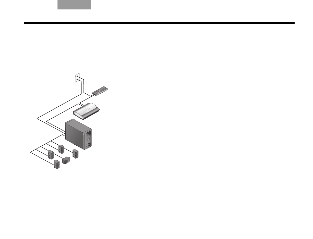
TAB 5TAB 4TAB 6TAB 8TAB 7English TAB 3Español
INTRODUCCIÓN
Simplificar la configuración
Las instrucciones detalladas siguientes le ayudarán a:
• Instalar el sistema donde usted desee.
• Conectar todos sus componentes.
• Seleccionar la opción idónea para conectar con
el televisor.
• Añadir dispositivos de audio o vídeo externos
al sistema.
• Personalizar el sonido al perfil de la habitación.
• Encender y probar las funciones y controles del
sistema.
Desembalar el sistema
Desembale cuidadosamente el sistema y guarde todos
los materiales de embalaje, que le permitirán
transportarlo de la forma más segura.
Si algún componente parece estar dañado, no lo
utilice. Comuníqueselo de inmediato a Bose
distribuidor Bose autorizado.
Encontrará la información de contacto de Bose en la
página de direcciones incluida con la caja.
Nota: Mientras desembala el producto podrá localizar
fácilmente los números de serie. Busque en la base del
centro de medios y el VS-2 y cerca del panel de conexión
del módulo Acoustimass
Le recomendamos que anote estos números en el
espacio suministrado en página iii por si necesita
consultarlos en el futuro.
®
.
®
o a su
3
Page 94
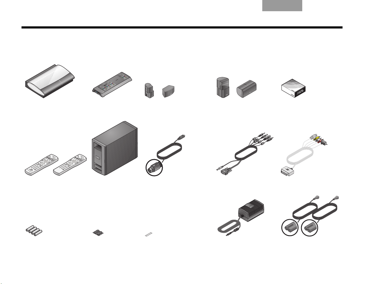
INTRODUCCIÓN
LIFESTYLE® 35/48 O BIEN
(4) (1)
LIFESTYLE® 28/38
(4) (1)
Mando a distancia del
sistema LIFESTYLE
®
38/48 28/35
O BIEN
Componentes incluidos
Mientras desembala el producto puede comprobar que incluye estos componentes.
EnglishTAB 6TAB 8 TAB 7 TAB 3TAB 5 EspañolTAB 4
o Centro de medios o Optimizador
o Mando a distancia o Módulo
o Pilas del mando
a distancia
4
de vídeo VS-2
Acoustimass
®
o Patas de goma
del módulo
Acoustimass
®
o Altavoces Jewel Cube®o Altavoces Direct/
Reflecting
o Cable de entrada
o Cable del VS-2 o Adaptador SCART
de audio
o Patas de goma
de los altavoces
o Fuente de
alimentación
®
o Sistema de calibración
de audio ADAPTiQ
®
(sólo para Europa)
o 2 cables de
alimentación de CA
Page 95
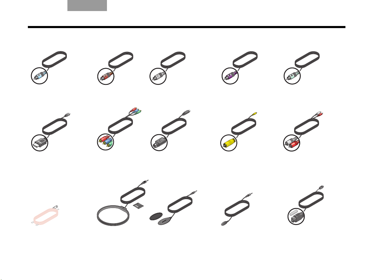
TAB 5TAB 4TAB 6TAB 8TAB 7English TAB 3Español
Azul claro
Marrón
Blanco
Morado
Verde claro
INTRODUCCIÓN
o Cable del altavoz
derecho
o Cable HDMI™ o Cable de
o Antena de FM o Antena de AM o Sensor de encendido/
o Cable del altavoz
central
vídeo por
componentes
o Cable del altavoz
izquierdo
o Cable de S-Video o Cable de vídeo
apagado del televisor
o Cable del altavoz
posterior derecho
compuesto
o Cable emisor de
infrarrojos
o Cable del altavoz
posterior izquierdo
o Cable de audio
estéreo
o Cable óptico
de audio
5
Page 96

INSTALAR EL SISTEMA
Seleccionar una
ubicación para
el sistema
1
Necesitará lo siguiente:
Centro de medios
Optimizador
de vídeo VS-2
5 altavoces Jewel Cube®
O
5 altavoces Direct/Reflecting
®
Módulo
Acoustimass
Patas de goma del
altavoz central
Patas de goma del
módulo Acoustimass®
EnglishTAB 6TAB 8 TAB 7 TAB 5 EspañolTAB 4
6
Page 97

TAB 5TAB 4TAB 6TAB 8TAB 7English TAB 3Español
A
l
ta
v
o
c
e
s
f
ro
n
ta
l
e
s
I
z
q
u
i
e
rd
o
C
e
n
tr
a
l
D
e
re
c
h
o
INSTALAR EL SISTEMA
Disponer el sistema en
la habitación
Para facilitar la instalación de los altavoces, Bose
ofrece pedestales para suelo y soportes para mesa y
para pared. También ofrecemos un kit de conexión
inalámbrica para los altavoces posteriores.
Si desea más información o solicitar accesorios,
llame al distribuidor Bose más cercano. Para ponerse
en contacto con Bose directamente, consulte la lista de
direcciones incluida.
Las imágenes siguientes muestran los altavoces
colocados sin utilizar soportes ni pedestales.
Colocar los altavoces frontales
y centrales
Estos tres altavoces frontales centran el diálogo y
crean un escenario de sonido amplio que corresponde
a lo que se ve en la pantalla.
1. Coloque las patas de goma
2. Coloque el altavoz central en posición horizontal
suministradas en el altavoz
central si se sitúa sobre un
estante, una mesa o un televisor.
sobre una superficie estable y plana.
Puede ir encima o debajo del televisor.
3. Sitúe un altavoz vertical a la
izquierda del televisor y otro a
la derecha.
Mantenga estos altavoces
izquierdo y derecho a un máximo de 1 m (3 pies)
de la pantalla del televisor para sincronizar el
sonido y el movimiento.
En la parte delantera de la habitación:
Compruebe lo siguiente:
• Los altavoces colocados en una estantería se
encuentran cerca del borde frontal.
En caso contrario, es posible que cambie la calidad
tonal del sonido.
7
Page 98

INSTALAR EL SISTEMA
A
l
t
a
v
o
c
e
s
p
o
s
t
e
r
i
o
r
e
s
I
z
q
u
i
e
r
d
o
D
e
r
e
c
h
o
EnglishTAB 6TAB 8 TAB 7 TAB 3TAB 5 EspañolTAB 4
Ubicar los altavoces posteriores
Estos dos altavoces se sitúan en la parte posterior de
la habitación para proporcionar sonido envolvente
realista cuando es necesario para efectos especiales.
Hacia la parte posterior de la habitación:
1. Coloque un altavoz a la izquierda y
el otro a la derecha de los
espectadores y mirando hacia la
parte delantera de la habitación.
Mantenga estos dos altavoces tan lejos de los
espectadores como resulte práctico.
Compruebe lo siguiente:
• No oriente los altavoces hacia los oyentes para evitar
que la fuente del sonido resulte obvia.
• Gire la parte superior de los cuatro
altavoces verticales que se encuentran en
la parte delantera y trasera de la habitación.
Esto ayudará a crear el sonido realista para
el que se ha diseñado el sistema.
Nota: Durante la colocación, es posible que descubra
que necesita cables adicionales. Podrá obtenerlos a
través de un distribuidor Bose.
Si prefiere ponerse en contacto con Bose directamente,
consulte la lista de direcciones incluida con el sistema o
visite la página web de Bose en: www.Bose.com.
2. Coloque los altavoces a la altura del oído (de un
oyente sentado) o más altos si es posible.
8
Page 99

TAB 5TAB 4TAB 6TAB 8TAB 7English TAB 3Español
C
e
n
t
r
o
d
e
m
e
d
i
o
s
Espacio
para otros
dispositivos
V
S-
2
INSTALAR EL SISTEMA
Disponer el centro de medios y el VS-2
Coloque el centro de medios y el optimizador de vídeo
VS-2 de modo que pueda acceder a ellos fácilmente al
realizar las conexiones.
Cuando termine de realizar las conexiones podrá
mover las dos unidades a su posición final.
Con el VS-2 cerca (detrás) del centro de medios:
1. Coloque el centro de
medios sobre una
superficie plana
y estable.
Deje espacio para
levantar la tapa frontal y
abrir la bandeja de
discos del centro de
medios. Evite asimismo
cualquier elemento que
le impida ver la ventana
de la pantalla frontal.
2. Coloque el VS-2 detrás
del centro de medios,
sobre el suelo, en una
estantería del centro de
entretenimiento o
montado en la pared.
Compruebe lo siguiente:
• El VS-2 y el centro de medios se encuentran a una
distancia de 1,8 m (6 pies).
• Hay una toma de alimentación de CA (red eléctrica) a
menos de 3 m (10 pies) del VS-2.
• Los cables de vídeo de otros dispositivos (receptor
de cable/satélite, DVR, reproductor de vídeo, etc.)
llegan al VS-2.
• Los cables de audio de estos dispositivos llegan al
centro de medios.
9
Page 100

INSTALAR EL SISTEMA
Módulo
Acoustimass
EnglishTAB 6TAB 8 TAB 7 TAB 3TAB 5 EspañolTAB 4
Ubicar el módulo de Acoustimass®
Este altavoz produce sonidos de graves profundos que
permiten sentir la acción que se desarrolla en la
pantalla, no sólo oírla.
1. Pegue las
Nota: Mantenga el módulo apoyado temporalmente
sobre un lado o boca abajo para realizar las conexiones
fácilmente. Cuando termine las conexiones, coloque el
módulo en la ubicación y la posición que haya elegido.
2. Sitúe el módulo en el mismo punto de la habitación
patas de
goma
autoadhesivas
a la superficie
inferior del
módulo.
Estas patas
proporcionan
estabilidad y protegen el suelo y el módulo.
que el televisor y los tres altavoces frontales.
Ahora puede colocar un lado contra la pared u
orientar la parte frontal hacia la habitación, NO
hacia una pared o una esquina.
Evite colocar el módulo a la misma distancia de
dos paredes o entre el techo y el suelo.
Mantenga el módulo a un mínimo de 0,5 m
(18 pulgadas) del televisor para evitar
interferencias y a 0,8 m de cintas de audio o vídeo
para evitar que sufran daños magnéticos.
3. Coloque el módulo sobre un lado o la superficie
inferior, pero NO de pie sobre uno de los extremos.
Puede situarlo detrás del sofá o de una silla,
debajo de una mesa o detrás de las cortinas.
PRECAUCIÓN: No bloquee las aberturas de ventilación
de la parte frontal y posterior del módulo.
10
 Loading...