

Page 1
402
®
Series II Loudspeaker
©2009 Bose Corporation
Service Manual
Reference Number 260431-SM Rev. 02
Electronic copy only
Page 2
External dimensions:
CONTENTS
Specifications ....................................................................................................................................1
Disassembly/Assembly Procedures ........................................................................................... 2-3
Figure 1. Schematic Diagram ..............................................................................................................3
Test Procedures ................................................................................................................................4
Main Part List..................................................................................................................................... 5
Figure 2. Exploded View ......................................................................................................................5
Crossover PCB Part List ..................................................................................................................6
Figure 3. Crossover PCB Layout ........................................................................................................6
Packaging Part List ...........................................................................................................................6
Figure 4. Packaging View ....................................................................................................................6
WARRANTY
5 year limited warranty
PROPRIETARY INFORMATION
THIS DOCUMENT CONTAINS PROPRIETARY INFORMATION
OF BOSE
ONLY FOR THE PURPOSE OF SERVICING THE IDENTIFIED
BOSE PRODUCT BY AN AUTHORIZED BOSE SERVICE CENTER OR OWNER OF THE BOSE PRODUCT, AND SHALL NOT
BE REPRODUCED OR USED FOR ANY OTHER PURPOSE.
®
CORPORATION WHICH IS BEING FURNISHED
SPECIFICATIONS
Single speaker: 23.3" H x 8.2" W x 7.8" D (59.2 x 20.8 x 19.8)cm
Packed system: 27.0" H x 12.0" W x 11.0" D (68.6 x 30.5 x 27.9)cm
Weight:
Single speaker: 17.5 lbs (7.94 kg)
Packed system: 21.3 lbs (9.66 kg)
Transducer:
Internal cabinet volume:
Port:
Type: Two rectangular ports located at the top and bottom.
Total port area: 8.84 sq. in. (57 sq. cm)
Port length: 3.23" (8.2cm)
Resonance frequency: 90 Hz
Impedance:
Power handling:
Sensitivity:
Four 4.5" environmental drivers per enclosure
1067.9 cu. In. (17.5 liters)
8 ± 2 Ohm
120W continuous per IEC-268-5
90 dB SPL, 1W, 1m
2
Page 3
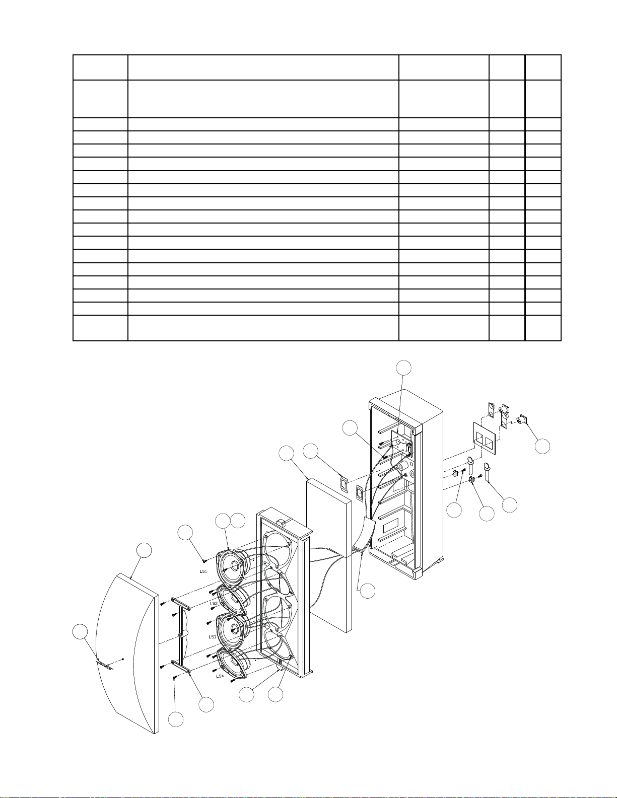
MAIN PART LIST
Item
Description Part Number Qty Note
Number
1 GRILLE, BLACK
GRILLE, ARCTIC WHITE
GRILLE, PRO GRAY
252380-001
252380-002
252380-004
1
2 SCREW, TAPP, 8 -15, HEXW, SLOT 290290-12 14
3 DRIVER ASSEMBLY, 4.5" 291020-001 4 1
4 GASKET, DRIVE R, 4. 5 " 128407 4
5 FOAM, ACOUSTIC, 19.75"x7"x1 120357 1
6 CLIP, TINNERMAN 187943 2
7 CROSSOVER ASSEMBLY 291042-001 1
8 CONN, SPEA KON, PANEL MOU NT 258213-002 2
9 SCREW, THUM B, M8x1.25x25mm 137050 2
10 CONN, FUSE CLIP, 1 POS, FEMAL E 121112 2
11 SCREW, TAPP, 6 - 20x.5, PAN, XR 290296-08 2
12 TAPE, FOAM 257555 1
13 NUT, J-TYPE, 8-32 109481 12
14 INSERT, KNURLED 290293-01 4
15 DEFLECTOR 126973-1 1
16 SCREW, TAPP, 6- 13x.625, PAN 290294-10 4
17 NAME PLATE, LOGO, BLACK
NAME PLATE, LOGO, WHITE
254458-001
254458-002
1
Note: When ordering a d river, also order a driver gasket.
17
7
2
2x
2x
2x
6
5
8
10
2x
9
12x
11
4x
4
3
2x
2
2x
1
12
12x
4x
13
14
15
16
4x
Figure 1. Exploded View
3
Page 4

Number
Qty
CROSSOVER PCB PART LIST
Item
Description
Part Num b er
Qty Note
Item
Description Part
Number
1 LAMP, AXIAL LEAD 114462 2
2 20uF, CAP, FILM, 75V, 10% 119026 1
x2
2
1
Figure 2. Crossover PCB Layout
PACKAGING PART LIST
Number
1 PACKING, FOAM, BOTTOM, EPS 258908 1
2 PACKING, FOAM, P/U, RIGHT 258927 2
3 PACKING, FOAM, P/U, LEFT 258928 2
4 MANUAL, OWNERS 256597 1
5 BAG, POLY, 13.5x 35x9.5 x1 MIL 114522 1
6 CARTON, RSC, 402 II 256591 1
3
2
1
6
4
2
3
5
Figure 3 Packaging View
4
Page 5

DISASSEMBLY/ASSEMBLY PROCEDURES
Note: Numbers in parenthesis correspond to
call-outs in figure 1.
1. Grille Removal
1.1 Rotate the Bose® logo (9) 450 to release
the grille (6).
1.2 Grasp the edge of the grill and pull it off.
0
45
2. Grille Replacement
2.1 Rotate the Bose logo (9) 450 so the
locking tabs on the logo line up with the slot
on the deflector (8). Press the grille into place.
2.2 Rotate the Bose logo horizontally, locking
the grille into place.
3. Driver Removal
3.4 Cut the wires as close as possible to the
driver’s wire terminal.
4. Driver Replacement
4.1 Referring to the schematic below, attach
the wires to the driver (1).
4.2 Line up the driver (1) to the cabinet and
secure it with three screws (7).
4.3 Line up the deflector (8) with the cabinet
and secure it with four screws (12).
5. Crossover Removal
5.1 Remove the three screws (7) securing the
top driver (1) to the cabinet. Lift out the driver.
5.2 Remove the two screws (7) securing the
crossover PCB to the cabinet.
5.3 Pull the crossover PCB through the driver
opening in the cabinet.
3.1 Perform procedure 1.
3.2 Remove the four screws (12) securing the
deflector (8) to the cabinet. Lift off the deflector.
Deflector
3.3 Remove the three screws (7) securing the
driver (1) to the cabinet. Lift out the driver.
Crossover PCB
5
Page 6

DISASSEMBLY/ASSEMBLY PROCEDURES
6. Crossover Replacement
6.1 Replace the two screws (7) securing the
crossover PCB (3) to the cabinet.
6.2 Perform procedure 4 and 2.
7. Speakon Connector Removal
7.1 Perform procedure 3.1-3.3 to remove the
two center drivers.
7.2 Using a flat-blade screwdriver, pry out the
tinnerman clip (5) securing the Speakon
connector (4) to the cabinet.
Speakon
Connector
Tinnerman Clip
7.3 Pull out the Speakon connector and
remove the wires.
8. Speakon Connector Replacement
8.1 Referring to figure 1, attach the wires to
the Speakon connector (4).
8.2 Align the Speakon connector in the
cabinet.
8.3 Reshape the tinnerman clip (5) or use a
new one. Place an appropriate size wood
block between the Speakon connector (rear
of speaker) and a hard surface. Using a flatblade screwdriver (or similar tool) and a
hammer, secure the tinnerman clip into place.
Make sure the Speakon connector is securely
fastened.
Figure 4. Schematic Diagram
6
Page 7

TEST PROCEDURES
1. Phase Test
1.1 Observing polarity, apply 9 VDC to the
input connector. Refer to the figure below.
1.2 All driver cones should move outward.
Referring to figure 4, rewire any driver that
moves inward.
1+
2-
1-
2+
Positive input
Negative input
2. Crossover Test
2.1 Connect a 0.5 Ohm resistor and amplifier
to the speaker input connector as shown in
the diagram below.
noise can be made to go away or get worse, it
is a rub or tick and the driver should be
replaced. If the noise stays the same, it is
normal suspension noise and the driver is
fine. Suspension noises will not be heard with
program material.
4. Air Leak Test
4.1 Apply a 15 Vrms, 65 Hz signal to the
speaker input connector.
4.2 Listen for air leaks around the drivers and
cabinet seam. Reposition or replace any
gasket that is found to leak. Repairs made to
the cabinet seam should not be visible from
the exterior of the speaker.
5. Sweep Test
5.1 Apply a 9 Vrms, 10 Hz signal to the
speaker input connector.
Amplifier
Speaker output
-
+
Volt meter
-
0.5 Ohm
Speaker
+
+
-
2.2 Apply a 2 Vrms, 8 kHz signal to the
speaker input connector.
2.3 Measure the voltage across the 0.5 Ohm
resistor. It should be 68-90 mVrms. If the
voltage is out of range, check the crossover
components and wiring.
3. Rub and Tick Test
3.1 Apply a 9 Vrms, 10 Hz signal to the
speaker input connector.
5.2 Sweep the signal generator from 10 Hz to
500 Hz.
5.3 Apply a 500 Hz, 2 Vrms signal to the
speaker input connector.
5.4 Sweep the signal generator from 500 Hz
to 5 kHz.
5.5 Listen for buzzes, rattles or other noises.
Redress any wire that buzzes; replace any
driver that is found to be defective.
Note: A whooshing noise from the port at its
resonance frequency of approximately 90 Hz
is acceptable.
3.2 No extraneous noises such as rubbing,
scraping or ticking should be heard.
Note: To distinguish between normal suspension noise and rubs or ticks, slightly displace
the cone of the driver with your fingers. If the
7
Page 8

SERVICE MANUAL REVISION HISTORY
Date Revision
Description of Change Change Driven By Pages
1
Level
02/01 00 Document release revision 00
02/06 01 Added RoHS part numbers This product is now built
1/07 No change Corrected part number, Driver
Assembly, 4.5”
5/09 02 - New part numbers for
speaker parts and packaging
- Layout changed to reflect
current manuals
Service manual release All
with RoHS compliant parts.
Correct part number is
254451
Part changes
Service manual layout
change
Affected
3
3
3, 4
All
8
Page 9

Specifications and Features Subject to Change Without Notice
Bose Corporation
The Mountain
Framingham Massachusetts USA 01701
P/N 260431-SM Rev. 02 05/2009 (P) For Technical Assistance or Part Orders, Call 1-800-233-4408
http://serviceops.bose.com
 Loading...