

Bose 321GSX Owner Manual
3•2•1 GSX
DVD HOME ENTERTAINMENT SYSTEM
2ZQHU¶V*XLGH
*XtDGHXVDULR
1RWLFHG¶XWLOLWVDWLRQ
SAFETY INFORMATION
Please read this owner’s guide
Please take the time to follow this owner’s guide carefully. It will help you set up and operate your system properly,
and enjoy all of its advanced features. Save your owner’s guide for future reference.
WARNING:
WARNING:
shall not be placed on the apparatus. As with any electronic products, use care not to spill liquids in any part of the system. Liquids can cause a failure and/or a fire hazard.
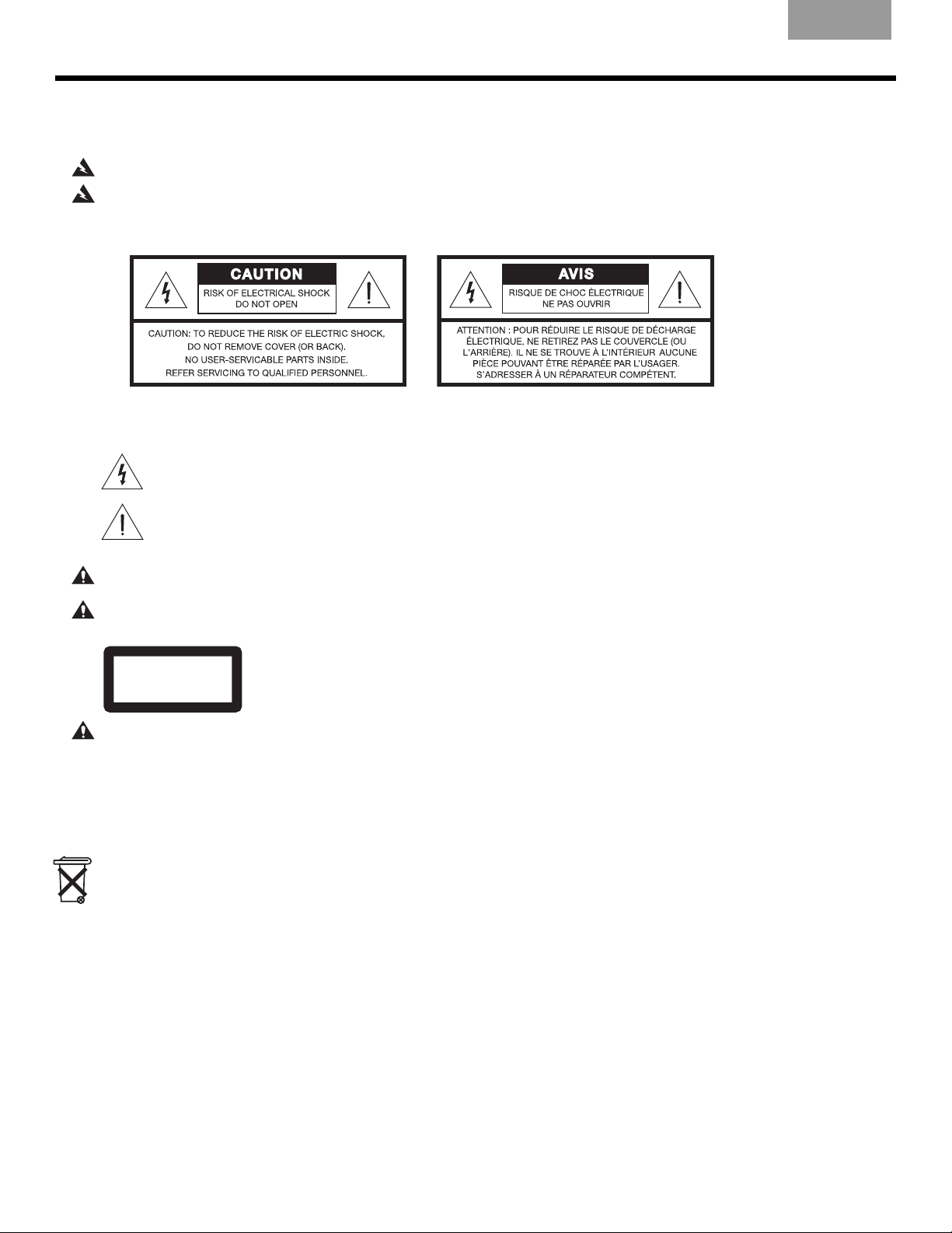
The CAUTION marks shown here are located on the bottom of your 3•2•1 GSX home entertainment system media
center and the rear panel of the Acoustimass module:
To reduce the risk of fire or electric shock, do not expose the system to rain or moisture.
This apparatus shall not be exposed to dripping or splashing, and objects filled with liquids, such as vases,
The lightning flash with arrowhead symbol, within an equilateral triangle, alerts the user to the presence of
uninsulated dangerous voltage within the system enclosure that may be of sufficient magnitude to constitute a risk of electric shock.
EnglishFrançais Español
The exclamation point within an equilateral triangle alerts the user to the presence of important operating
and maintenance instructions in this owner’s guide.
CAUTION:
CAUTION:
To prevent electric shock, match wide blade of plug to wide slot, insert fully.
No naked flame sources, such as lighted candles, should be placed on the apparatus.
Class 1 laser product
CLASS 1 LASER PRODUCT
KLASSE 1 LASER PRODUKT
LUOKAN 1 LASER LAITE
KLASS 1 LASER APPARAT
CAUTION:
Use of controls or adjustments or performance of procedures other than those specified herein may result
in hazardous radiation exposure. The DVD player should not be adjusted or repaired by anyone except properly qualified
service personnel.
The DVD player within the media center is classified as a CLASS 1 LASER PRODUCT
according to EN60825-1:1994 + A1+A2, IEC60825-1:1993+A1+A2.
Class B emissions limits
This Class B digital apparatus meets all requirements of the Canadian Interference-Causing Equipment Regulations.
Batteries
Please dispose of used batteries properly, following any local regulations. Do not incinerate.
Additional safety information
See the additional instructions on the
Important Safety Information
sheet enclosed in the shipping carton.
%RVH&RUSRUDWLRQ1RSDUWRIWKLVZRUNPD\EHUHSURGXFHGPRGLILHGGLVWULEXWHGRURWKHUZLVHXVHGZLWKRXWSULRUZULWWHQSHUPLVVLRQ
7KHGLVWLQFWLYHGHVLJQRIWKHPHGLDFHQWHULVDOVRDUHJLVWHUHGWUDGHPDUNRI%RVH&RUSRUDWLRQ
0DQXIDFWXUHGXQGHUOLFHQVHIURP'ROE\/DERUDWRULHV³'ROE\´DQGWKHGRXEOH'V\PERODUHWUDGHPDUNVRI'ROE\/DERUDWRULHV&RQILGHQWLDO8QSXEOLVKHG
:RUNV'ROE\/DERUDWRULHV$OOULJKWVUHVHUYHG
7KLVSURGXFWFRQWDLQVRQHRUPRUHSURJUDPVSURWHFWHGXQGHULQWHUQDWLRQDODQG86FRS\ULJKWODZVDVXQSXEOLVKHGZRUNV7KH\DUHFRQILGHQWLDODQGSUR
SULHWDU\WR'ROE\/DERUDWRULHV7KHLUUHSURGXFWLRQRUGLVFORVXUHLQZKROHRULQSDUWRUWKHSURGXFWLRQRIGHULYDWLYHZRUNVWKHUHIURPZLWKRXWWKHH[SUHVVSHU
PLVVLRQRI'ROE\/DERUDWRULHVLVSURKLELWHG&RS\ULJKWE\'ROE\/DERUDWRULHV,QF$OOULJKWVUHVHUYHG
03(*/D\HUDXGLRFRPSUHVVLRQWHFKQRORJ\OLFHQVHGE\)UDXQKRIHU,,6DQG7+20621PXOWLPHGLD
³'76´DQG³'76'LJLWDO6XUURXQG´DUHUHJLVWHUHGWUDGHPDUNVRI'LJLWDO7KHDWHU6\VWHPV,QF
2

English FrançaisEspañol
C
ONTENTS
CONTENTS
INTRODUCTION
SYSTEM SETUP
SYSTEM CONTROLS AND INDICATORS
OPERATION
CHANGING SOURCE SETTINGS
CHANGING SYSTEM OPTIONS
MAINTAINING YOUR SYSTEM
TROUBLESHOOTING
INTRODUCTION 5
Before you begin . . . . . . . . . . . . . . . . . . . . . . . . . . . . . . . . . . . . . . . . . . . . . . . . . . . . . . . . . . . . . . . . . . . . . . . . . . . . . 5
System features . . . . . . . . . . . . . . . . . . . . . . . . . . . . . . . . . . . . . . . . . . . . . . . . . . . . . . . . . . . . . . . . . . . . . . . . . . . . . . 5
Introducing the uMusic
™
intelligent playback system . . . . . . . . . . . . . . . . . . . . . . . . . . . . . . . . . . . . . . . . . . . . . . . . . 5
Checking for region code compatibility . . . . . . . . . . . . . . . . . . . . . . . . . . . . . . . . . . . . . . . . . . . . . . . . . . . . . . . . . . . . 5
Selecting compatible discs . . . . . . . . . . . . . . . . . . . . . . . . . . . . . . . . . . . . . . . . . . . . . . . . . . . . . . . . . . . . . . . . . . . . . 6
Glossary of terms . . . . . . . . . . . . . . . . . . . . . . . . . . . . . . . . . . . . . . . . . . . . . . . . . . . . . . . . . . . . . . . . . . . . . . . . . . . . . 6
Limited warranty . . . . . . . . . . . . . . . . . . . . . . . . . . . . . . . . . . . . . . . . . . . . . . . . . . . . . . . . . . . . . . . . . . . . . . . . . . . . . . 7
SYSTEM SETUP 8
Unpacking . . . . . . . . . . . . . . . . . . . . . . . . . . . . . . . . . . . . . . . . . . . . . . . . . . . . . . . . . . . . . . . . . . . . . . . . . . . . . . . . . . 8
Selecting locations for your 3•2•1 GSX system components . . . . . . . . . . . . . . . . . . . . . . . . . . . . . . . . . . . . . . . . . . . 9
Positioning the media center . . . . . . . . . . . . . . . . . . . . . . . . . . . . . . . . . . . . . . . . . . . . . . . . . . . . . . . . . . . . . . . 9
Positioning the speakers . . . . . . . . . . . . . . . . . . . . . . . . . . . . . . . . . . . . . . . . . . . . . . . . . . . . . . . . . . . . . . . . . . 10
Positioning the Acoustimass
Making system connections . . . . . . . . . . . . . . . . . . . . . . . . . . . . . . . . . . . . . . . . . . . . . . . . . . . . . . . . . . . . . . . . . . . . 12
Connecting the Acoustimass module to the media center . . . . . . . . . . . . . . . . . . . . . . . . . . . . . . . . . . . . . . . . 12
Connecting the speakers to the Acoustimass module . . . . . . . . . . . . . . . . . . . . . . . . . . . . . . . . . . . . . . . . . . . 12
Connecting the supplied antennas . . . . . . . . . . . . . . . . . . . . . . . . . . . . . . . . . . . . . . . . . . . . . . . . . . . . . . . . . . . 14
Connecting cable FM radio . . . . . . . . . . . . . . . . . . . . . . . . . . . . . . . . . . . . . . . . . . . . . . . . . . . . . . . . . . . . . . . . 14
Connecting your TV to the media center . . . . . . . . . . . . . . . . . . . . . . . . . . . . . . . . . . . . . . . . . . . . . . . . . . . . . . . . . . . 15
Making audio connections . . . . . . . . . . . . . . . . . . . . . . . . . . . . . . . . . . . . . . . . . . . . . . . . . . . . . . . . . . . . . . . . . 15
Making composite video connections . . . . . . . . . . . . . . . . . . . . . . . . . . . . . . . . . . . . . . . . . . . . . . . . . . . . . . . . 15
Connecting your TV and VCR to the media center . . . . . . . . . . . . . . . . . . . . . . . . . . . . . . . . . . . . . . . . . . . . . . . . . . . 16
Option A: TV (with audio output jacks) + VCR + media center . . . . . . . . . . . . . . . . . . . . . . . . . . . . . . . . . . . . . 16
Option B: TV (NO audio output jacks) + VCR + media center . . . . . . . . . . . . . . . . . . . . . . . . . . . . . . . . . . . . . . 17
VCR considerations . . . . . . . . . . . . . . . . . . . . . . . . . . . . . . . . . . . . . . . . . . . . . . . . . . . . . . . . . . . . . . . . . . . . . . 18
Advanced setup options . . . . . . . . . . . . . . . . . . . . . . . . . . . . . . . . . . . . . . . . . . . . . . . . . . . . . . . . . . . . . . . . . . . . . . . 18
Making S-video connections (higher quality video) . . . . . . . . . . . . . . . . . . . . . . . . . . . . . . . . . . . . . . . . . . . . . . 18
Making component video connections (highest quality video) . . . . . . . . . . . . . . . . . . . . . . . . . . . . . . . . . . . . . 19
Connecting digital audio devices . . . . . . . . . . . . . . . . . . . . . . . . . . . . . . . . . . . . . . . . . . . . . . . . . . . . . . . . . . . . 20
Connecting your cable/satellite box, TV, and VCR to the media center . . . . . . . . . . . . . . . . . . . . . . . . . . . . . . 20
Connecting a game console . . . . . . . . . . . . . . . . . . . . . . . . . . . . . . . . . . . . . . . . . . . . . . . . . . . . . . . . . . . . . . . . 22
Installing the remote control batteries . . . . . . . . . . . . . . . . . . . . . . . . . . . . . . . . . . . . . . . . . . . . . . . . . . . . . . . . . . . . . 23
Connecting the power cord . . . . . . . . . . . . . . . . . . . . . . . . . . . . . . . . . . . . . . . . . . . . . . . . . . . . . . . . . . . . . . . . . . . . . 24
Verifying your system setup . . . . . . . . . . . . . . . . . . . . . . . . . . . . . . . . . . . . . . . . . . . . . . . . . . . . . . . . . . . . . . . . . . . . . 25
®
module . . . . . . . . . . . . . . . . . . . . . . . . . . . . . . . . . . . . . . . . . . . . . . . . . . . . . . . . 11
5
8
26
35
48
53
64
66
SYSTEM CONTROLS AND INDICATORS 26
Remote control . . . . . . . . . . . . . . . . . . . . . . . . . . . . . . . . . . . . . . . . . . . . . . . . . . . . . . . . . . . . . . . . . . . . . . . . . . . . . . . 26
Setting up your remote to control other audio/video devices . . . . . . . . . . . . . . . . . . . . . . . . . . . . . . . . . . . . . . . . . . . 30
Direct entry of a device code . . . . . . . . . . . . . . . . . . . . . . . . . . . . . . . . . . . . . . . . . . . . . . . . . . . . . . . . . . . . . . . 30
Searching for a device code . . . . . . . . . . . . . . . . . . . . . . . . . . . . . . . . . . . . . . . . . . . . . . . . . . . . . . . . . . . . . . . . 31
Verifying an entered device code . . . . . . . . . . . . . . . . . . . . . . . . . . . . . . . . . . . . . . . . . . . . . . . . . . . . . . . . . . . . 33
Changing channel selection control . . . . . . . . . . . . . . . . . . . . . . . . . . . . . . . . . . . . . . . . . . . . . . . . . . . . . . . . . . . . . . . 33
Media center . . . . . . . . . . . . . . . . . . . . . . . . . . . . . . . . . . . . . . . . . . . . . . . . . . . . . . . . . . . . . . . . . . . . . . . . . . . . . . . . 34
3

EnglishFrançais Español
OPERATION 35
Turning your system on and off . . . . . . . . . . . . . . . . . . . . . . . . . . . . . . . . . . . . . . . . . . . . . . . . . . . . . . . . . . . . . . . . . . 35
Playing video DVDs . . . . . . . . . . . . . . . . . . . . . . . . . . . . . . . . . . . . . . . . . . . . . . . . . . . . . . . . . . . . . . . . . . . . . . . . . . . 35
Basic DVD operations . . . . . . . . . . . . . . . . . . . . . . . . . . . . . . . . . . . . . . . . . . . . . . . . . . . . . . . . . . . . . . . . . . . . 36
Restricting access to video DVDs . . . . . . . . . . . . . . . . . . . . . . . . . . . . . . . . . . . . . . . . . . . . . . . . . . . . . . . . . . . 36
Playing audio CDs . . . . . . . . . . . . . . . . . . . . . . . . . . . . . . . . . . . . . . . . . . . . . . . . . . . . . . . . . . . . . . . . . . . . . . . . . . . . 37
Listening to FM/AM radio . . . . . . . . . . . . . . . . . . . . . . . . . . . . . . . . . . . . . . . . . . . . . . . . . . . . . . . . . . . . . . . . . . . . . . . 38
Tuning to a station . . . . . . . . . . . . . . . . . . . . . . . . . . . . . . . . . . . . . . . . . . . . . . . . . . . . . . . . . . . . . . . . . . . . . . . 38
Storing stations as presets . . . . . . . . . . . . . . . . . . . . . . . . . . . . . . . . . . . . . . . . . . . . . . . . . . . . . . . . . . . . . . . . . 38
Erasing a preset . . . . . . . . . . . . . . . . . . . . . . . . . . . . . . . . . . . . . . . . . . . . . . . . . . . . . . . . . . . . . . . . . . . . . . . . . 38
Using the uMusic™ intelligent playback system . . . . . . . . . . . . . . . . . . . . . . . . . . . . . . . . . . . . . . . . . . . . . . . . . . . . . 39
Storing CDs . . . . . . . . . . . . . . . . . . . . . . . . . . . . . . . . . . . . . . . . . . . . . . . . . . . . . . . . . . . . . . . . . . . . . . . . . . . . 39
Playing stored music . . . . . . . . . . . . . . . . . . . . . . . . . . . . . . . . . . . . . . . . . . . . . . . . . . . . . . . . . . . . . . . . . . . . . 40
Rating your music . . . . . . . . . . . . . . . . . . . . . . . . . . . . . . . . . . . . . . . . . . . . . . . . . . . . . . . . . . . . . . . . . . . . . . . . 42
Stored music play modes . . . . . . . . . . . . . . . . . . . . . . . . . . . . . . . . . . . . . . . . . . . . . . . . . . . . . . . . . . . . . . . . . . 42
Repeat and shuffle functions . . . . . . . . . . . . . . . . . . . . . . . . . . . . . . . . . . . . . . . . . . . . . . . . . . . . . . . . . . . . . . . 42
Deleting stored tracks . . . . . . . . . . . . . . . . . . . . . . . . . . . . . . . . . . . . . . . . . . . . . . . . . . . . . . . . . . . . . . . . . . . . 43
Using uMusic presets . . . . . . . . . . . . . . . . . . . . . . . . . . . . . . . . . . . . . . . . . . . . . . . . . . . . . . . . . . . . . . . . . . . . . 43
Using the Playlist . . . . . . . . . . . . . . . . . . . . . . . . . . . . . . . . . . . . . . . . . . . . . . . . . . . . . . . . . . . . . . . . . . . . . . . . 45
Searching through your music library . . . . . . . . . . . . . . . . . . . . . . . . . . . . . . . . . . . . . . . . . . . . . . . . . . . . . . . . 46
Registering your system for music information updates . . . . . . . . . . . . . . . . . . . . . . . . . . . . . . . . . . . . . . . . . . 47
CHANGING SOURCE SETTINGS 48
Using the settings menus . . . . . . . . . . . . . . . . . . . . . . . . . . . . . . . . . . . . . . . . . . . . . . . . . . . . . . . . . . . . . . . . . . . . . . . 48
Stored CD settings menu . . . . . . . . . . . . . . . . . . . . . . . . . . . . . . . . . . . . . . . . . . . . . . . . . . . . . . . . . . . . . . . . . . . . . . . 50
FM/AM settings menu . . . . . . . . . . . . . . . . . . . . . . . . . . . . . . . . . . . . . . . . . . . . . . . . . . . . . . . . . . . . . . . . . . . . . . . . . 50
CD settings menu . . . . . . . . . . . . . . . . . . . . . . . . . . . . . . . . . . . . . . . . . . . . . . . . . . . . . . . . . . . . . . . . . . . . . . . . . . . . . 50
DVD settings menu . . . . . . . . . . . . . . . . . . . . . . . . . . . . . . . . . . . . . . . . . . . . . . . . . . . . . . . . . . . . . . . . . . . . . . . . . . . 51
TV, CBL-SAT, and AUX settings menu . . . . . . . . . . . . . . . . . . . . . . . . . . . . . . . . . . . . . . . . . . . . . . . . . . . . . . . . . . . . 52
CHANGING SYSTEM OPTIONS 53
Using the System menu . . . . . . . . . . . . . . . . . . . . . . . . . . . . . . . . . . . . . . . . . . . . . . . . . . . . . . . . . . . . . . . . . . . . . . . . 53
Stored CD options . . . . . . . . . . . . . . . . . . . . . . . . . . . . . . . . . . . . . . . . . . . . . . . . . . . . . . . . . . . . . . . . . . . . . . . . . . . . 54
Audio options . . . . . . . . . . . . . . . . . . . . . . . . . . . . . . . . . . . . . . . . . . . . . . . . . . . . . . . . . . . . . . . . . . . . . . . . . . . . . . . . 58
Video options . . . . . . . . . . . . . . . . . . . . . . . . . . . . . . . . . . . . . . . . . . . . . . . . . . . . . . . . . . . . . . . . . . . . . . . . . . . . . . . . 59
Media center options . . . . . . . . . . . . . . . . . . . . . . . . . . . . . . . . . . . . . . . . . . . . . . . . . . . . . . . . . . . . . . . . . . . . . . . . . . 60
Remote control options . . . . . . . . . . . . . . . . . . . . . . . . . . . . . . . . . . . . . . . . . . . . . . . . . . . . . . . . . . . . . . . . . . . . . . . . 61
DVD Lock options . . . . . . . . . . . . . . . . . . . . . . . . . . . . . . . . . . . . . . . . . . . . . . . . . . . . . . . . . . . . . . . . . . . . . . . . . . . . 62
MAINTAINING YOUR SYSTEM 64
Cleaning . . . . . . . . . . . . . . . . . . . . . . . . . . . . . . . . . . . . . . . . . . . . . . . . . . . . . . . . . . . . . . . . . . . . . . . . . . . . . . . . . . . . 64
Replacing the remote control batteries . . . . . . . . . . . . . . . . . . . . . . . . . . . . . . . . . . . . . . . . . . . . . . . . . . . . . . . . . . . . 65
Accessories . . . . . . . . . . . . . . . . . . . . . . . . . . . . . . . . . . . . . . . . . . . . . . . . . . . . . . . . . . . . . . . . . . . . . . . . . . . . . . . . . 65
TROUBLESHOOTING 66
Troubleshooting table . . . . . . . . . . . . . . . . . . . . . . . . . . . . . . . . . . . . . . . . . . . . . . . . . . . . . . . . . . . . . . . . . . . . . . . . . 66
Customer service . . . . . . . . . . . . . . . . . . . . . . . . . . . . . . . . . . . . . . . . . . . . . . . . . . . . . . . . . . . . . . . . . . . . . . . . . . . . . 67
TECHNICAL INFORMATION 68
ND USER LICENSE AGREEMENT 69
E
D
EVICE CODES A-1
4

English FrançaisEspañol
INTRODUCTION
Before you begin
System features
Thank you for purchasing the 3•2•1 GSX DVD home entertainment system, which offers
superb sound, elegance, and simplicity in an advanced home audio setup. Using Bose
prietary signal processing technology, the 3•2•1 GSX system provides improved spaciousness from stereo recordings, and bold movie effects from surround-encoded materials. Yet its
few parts require little effort to set up, so you can enjoy your new system’s performance right
away.
The following items are included to help you set up your system:
• Quick Setup Guide
• Detailed setup instructions in Setup section of this guide
• Setup DVD
• Integrated AM/FM tuner and DVD/CD player in a small media center
• uMusic™ intelligent playback system for storing and playing your favorite songs
• Small, easy-to-place shelf speakers and an attractive hideaway Acoustimass
• Easy-to-use universal infrared remote control
• Media center input jacks for a TV, cable/satellite box or other component such as a DVR
®
module
®
pro-
Introducing the uMusic™ intelligent playback system
INTRODUCTION
Your 3•2•1 GSX DVD home entertainment system includes the new uMusic intelligent
playback system – a breakthrough Bose technology that makes it possible to store and
enjoy your CD collection.
What can you do with this system?
• Store your favorite CDs in a music library. Your system can store approximately 200
hours of music or about 200 CDs.
• Teach the system which tracks your like or dislike, conditioning the system to automatically play the music you want to hear most.
• Discover many ways to enjoy your music.
Checking for region code compatibility
For a DVD player and DVD disc to be compatible, their region code numbers must match.
These numbers are allocated according to where the player and disc are sold. The 3•2•1
GSX DVD home entertainment systems have a region code which must also match the DVD
discs.
Check the region code number on the carton of the 3•2•1 GSX DVD home entertainment
system or on the bottom of the media center that comes in the carton. Then be sure to
choose only DVD discs that show the same region number on the disc label or front cover.
For example, a Region 1 DVD disc should display the following mark:
,QWURGXFWLRQIP
5
I
NTRODUCTION
Selecting compatible discs
The DVD/CD player built into the 3•2•1 GSX media center can play the following types of
discs identified by their corresponding logos:
EnglishFrançais Español
INTRODUCTION
Glossary of terms
• Video DVD
•Video CD
• DVD+R, DVD-R,
DVD+RW and
DVD-RW
Note:
Regarding copy protection – Music and other content may be protected by international
and domestic copyright laws and may contain specific restrictions on use and/or reproduction.
Please respect the rights of the artists and other copyright holders.
Aspect Ratio – The shape of the rectangular picture in a TV set. It is the width of the picture
relative to the height. Our standard TV picture, in terminology used by that industry, is 4 units
wide by 3 units high, or 4:3 (read as 4 by 3) in aspect ratio. There are currently two standard
TV aspect ratios, 4:3 and 16:9.
Chapter – In DVD-Video, a division of a title.
•Audio CD
•CD-R and CD-R/W
• MP3 CDs, where
– All tracks were burned in a single closed session
– The disc format is ISO9660
– Each file has a “.mp3” extension and the filename contains
no other periods
• SACDs (CD-compatible content only)
Component Video – A video signal split into three parts: luminance and two color signals
(marked as YPbPr). It provides the highest level of video quality.
Composite Video – A single video signal that contains luminance, color, and synchronization
information. NTSC and PAL are examples of composite video systems.
Dolby Laboratories – Developer of a perceptual coding system for audio.
Dolby Digital
DTS
DVD – An acronym that is most commonly known to mean Digital Video Disc or Digital
Versatile Disc. The audio/video/data storage system based on 12- and 8-cm optical discs.
DVD Video – A standard for storing and reproducing audio and video on DVD-ROM discs,
based on MPEG video, Dolby Digital and MPEG audio, and other proprietary data formats.
– A type of multi-channel surround sound format used on discs.
– A type of multi-channel surround sound format used on discs.
6
,QWURGXFWLRQIP

English FrançaisEspañol
I
NTRODUCTION
Gracenote – Music recognition technology and related data provided as part of the service
contracted by Bose.
IR – An acronym for infrared. Pertains to the type of remote that sends/receives commands
on an infrared light beam.
MPEG – A type of data compression used for audio or video storage on disc.
MP3 – MPEG-1 Layer III audio. This is a compressed audio format that allows you to record
many hours of music on a single CD.
NTSC – An acronym for National Television System Committee. The organization that devel-
oped both the American Black & White and Color television systems.
PAL – An acronym for Phase Alternate Line. A television format used extensively in Western
Europe.
Progressive Scan – A video format which displays all lines of the picture frame in a single
pass, and refreshes the TV image 30x/sec. Not compatible with all video displays.
PVR – An abbreviation for Personal Video Recording. Sometimes used interchangeably with
DVR for Digital Video Recording, but may include non-digital technology, as used in VCRs.
RDS – A system that displays radio broadcast station and programming information.This fea-
ture is available on European systems only.
SACD – An abbreviation for Super Audio Compact Disc, used for high-resolution digital audio
storage on CD-sized discs. New Bose
®
3•2•1 GSX systems play the CD-compatible portion
of such discs, identified by the CD disc logo on the front of the disc.
SCART – A type of jack commonly found on consumer electronics products manufactured
for use in Western Europe.
S-video – A video interface standard that carries separate luminance and chrominance
signals, usually on a four-pin mini-DIN connector. Also called Y/C. The quality of S-video is
significantly better than composite video since it does not require a comb filter to separate
the signals. Most high-end televisions have S-video inputs.
INTRODUCTION
Limited warranty
uMusic™ intelligent playback system – A revolutionary Bose play mode, which performs
like a virtual DJ by noting listener preferences and playing suitable stored CD tracks in
response.
Videostage
®
5 – Bose proprietary Videostage 5 decoding circuitry gives you a five-channel
surround sound experience from everything you listen to – VHS tapes, stereo CDs, even
mono TV programs.
Your 3•2•1 GSX DVD home entertainment system is covered by a limited transferable
warranty. Details of the limited warranty are provided on the product registration card that
came with your system. Please fill out the information section on the card and mail it to
Bose. Failure to do so will not affect your limited warranty rights.
,QWURGXFWLRQIP
7
SYSTEM SETUP
Unpacking
EnglishFrançais Español
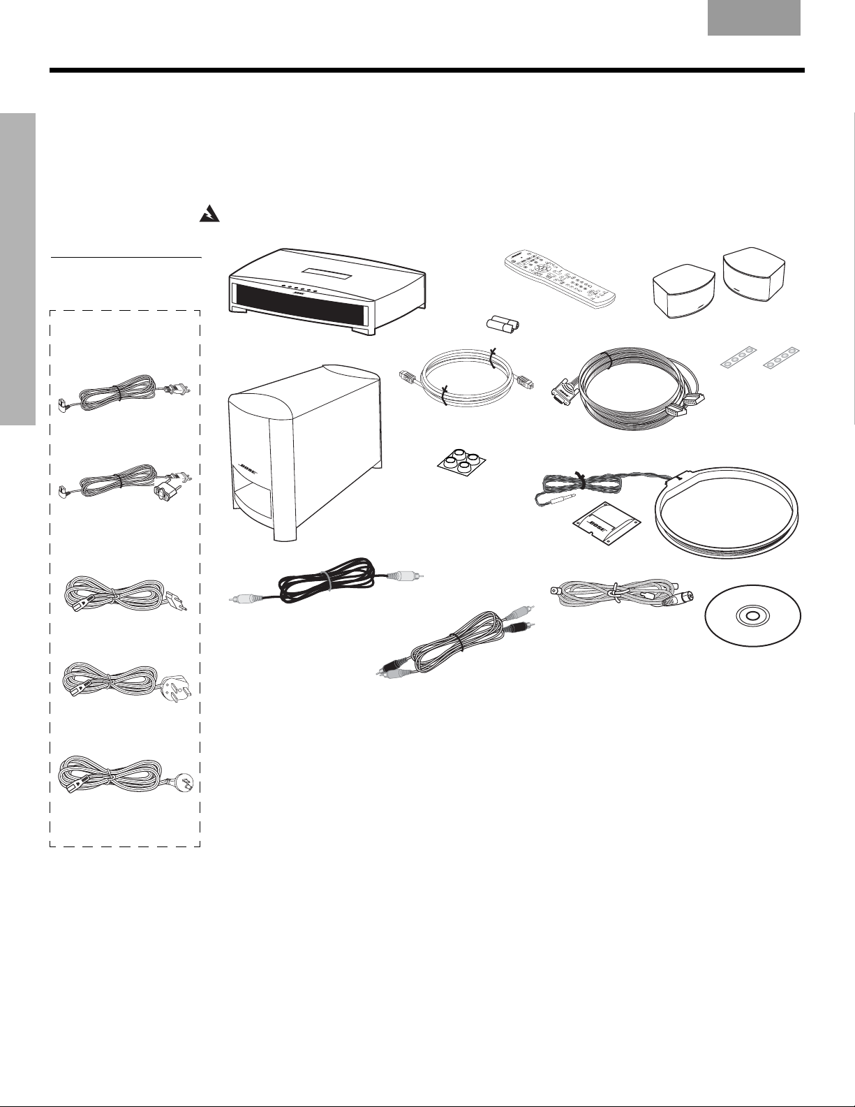
Carefully unpack your system. Save all packing materials, which provide the safest way to
transport your system. Check to be sure your system includes the parts shown in Figure 1.
SYSTEM SETUP
Figure 1
Contents of the shipping
carton
Your system includes
one of the following
cords:
120 VAC power cord
(US/Canada)
115/230 VAC power
cord with adapter
(US/Europe)
If any part of the system appears damaged, do not attempt to use it. Notify Bose or your
authorized Bose
®
dealer immediately. For Bose contact information, refer to the address
sheet included in the carton.
WARNING:
Media center
To avoid danger of suffocation, keep the plastic bags out of the reach of children.
Remote
control
®
Acoustimass
module
Acoustimass
module cable
Large rubber feet
for Acoustimass
module
®
Batteries
Antenna stand
Gemstone
Speaker cable
®
speaker arrays
Small rubber
feet for speaker
arrays
AM antenna
230 VAC power cord
(Europe)
230 VAC power cord
(UK/Singapore)
240 VAC power cord
(Australia)
Video cable
Stereo cable
FM antenna
Setup disc
For your records
Now is a good time to find the serial numbers on the bottom of the media center and on the
rear of the Acoustimass
Card. You will need to have them ready if you ever need to contact Bose
Media center serial number: _________________________________________________________
Acoustimass module serial number: __________________________________________________
Dealer name: ______________________________________________________________________
Dealer phone: __________________________ Purchase date: _____________________________
We suggest you keep your sales receipt and product registration together with this owner’s guide.
®
module. Please record them here and on your Product Registration
®
Customer Service.
8
6\VWHP6HWXSIP
English FrançaisEspañol
Selecting locations for your 3•2•1 GSX system components
S
YSTEM SETUP
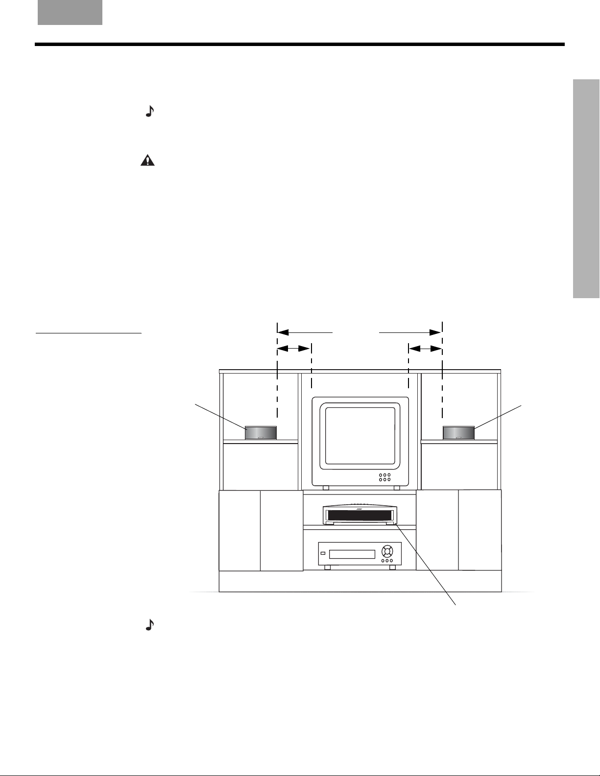
Figure 2
Sample media center and
speaker placement
Use the following guidelines and Figure 2 to choose locations and positions for the components of your 3•2•1 GSX home entertainment system.
Note:
While these guidelines are offered to help provide great system performance, you may find
other placement choices that are more convenient and provide the sound you enjoy.
Positioning the media center
CAUTION: Do not block any ventilation openings. For reliable operation of the product and to
protect it from overheating, put the product in a position and location that will not interfere with its
proper ventilation. For example, do not place the product on a bed, sofa, or similar surface that
may block the ventilation openings. Do not put it in a built-in system, such as a bookcase or cabinet that may keep air from flowing through its ventilation openings.
• Place the media center where nothing obstructs opening the disc tray on its front panel.
• Position the media center close enough to the Acoustimass
that all the cables will reach.
• Make sure the media center is close enough to additional source devices (TV, VCR or cable
box) so that all the cables will reach.
• Make sure that the front of the media center is unobstructed so that it may receive
IR (infrared) commands from the remote control.
3 ft (1 m)
3 ft (1 m)
maximum
minimum
®
module and the speakers so
3 ft (1 m)
maximum
SYSTEM SETUP
Left
speaker
Media center
Right
speaker
Note: The left and right speakers are magnetically shielded to prevent interference with your
TV screen.
6\VWHP6HWXSIP
9
S
YSTEM SETUP
SYSTEM SETUP
EnglishFrançais Español
Positioning the speakers
Choosing a good location for the speakers will allow you to experience the audio surround
effects that your 3•2•1 GSX home entertainment system is designed to deliver.
• Place the left and right speakers at least 3 feet (1 meter) apart from each other to optimize the surround sound experience (Figure 3).
• Place each speaker within 3 feet (1 meter) of the edge of the TV screen. Placing the
speakers more than 3 feet away from the TV can cause the sound to become separated
from the picture.
• If you are using a bookshelf or a home entertainment unit, place each speaker at the
front edge of its shelfPositioning the speakers too far back in an enclosed space can
change the overall quality of sound and alter the movie sound effects.
CAUTION:
ers to move, particularly on smooth surfaces like marble, glass, or highly polished wood. If you
are placing the speakers on a flat surface, be sure to attach one set of the small rubber feet to the
bottom surface of each speaker. You can obtain additional rubber feet (PN 178321) from Bose
Customer Service. To contact Bose, refer to the list of offices included in the product carton.
Note:
ing information, refer to “Accessories” on page 65. Additional or longer cables may also be
ordered.
Choose a stable and level surface for both speakers. Vibration can cause the speak-
®
The speakers can be mounted on Bose brackets, table stands, or floor stands. For order-
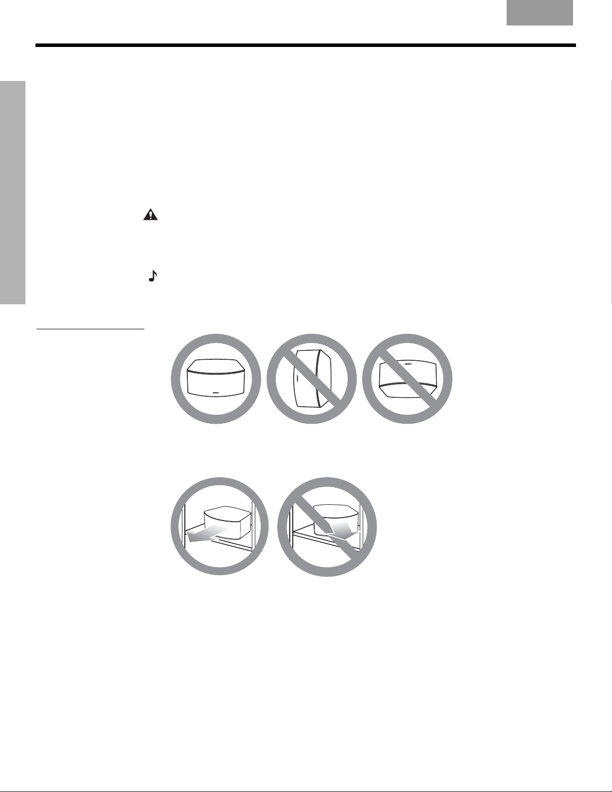
Figure 3
Recommended speaker
placement
•Set the speakers on their bottom surfaces, only, with the Bose logo right-side up.
• Aim the speakers straight ahead into the listening area. Do not place the speakers at an
angle. Angling one or both speakers into or away from the listening area signifi-
cantly alters system performance.
10
6\VWHP6HWXSIP
English FrançaisEspañol
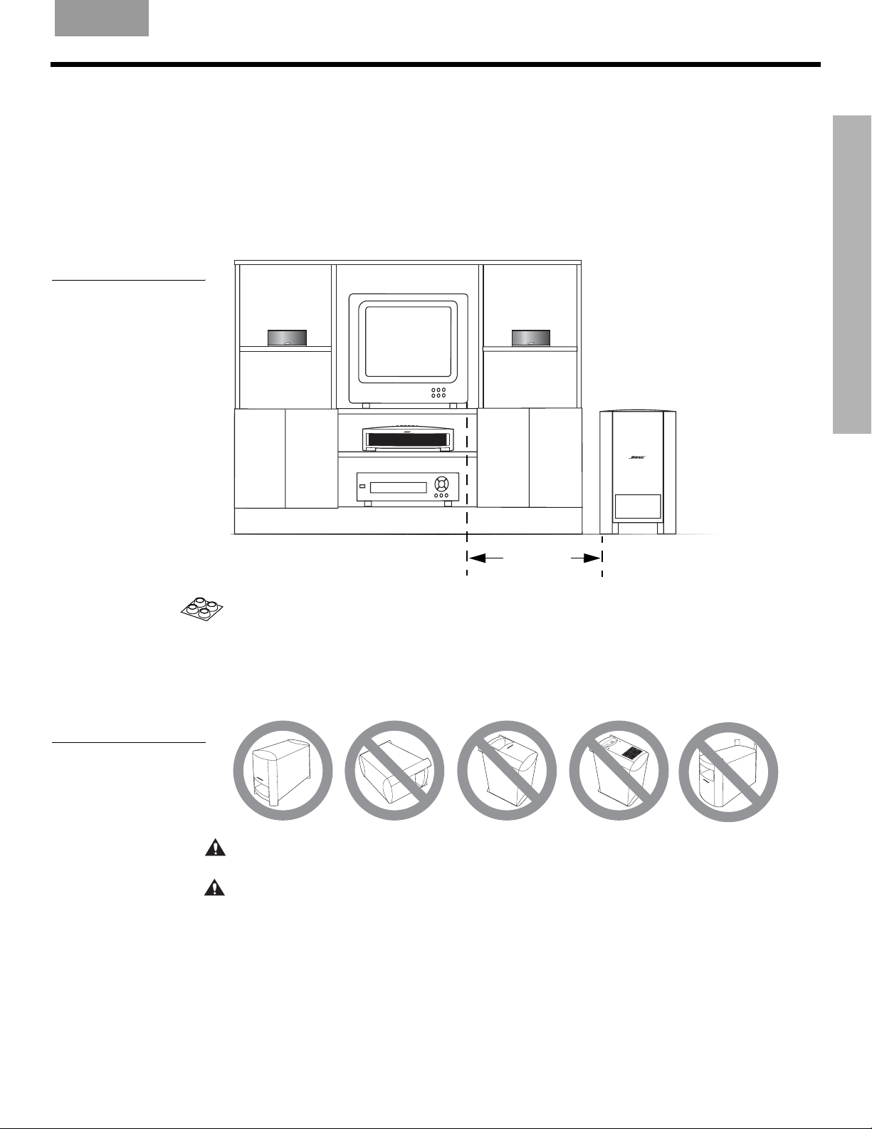
Figure 4
Recommended
Acoustimass module
placement
S
YSTEM SETUP
Positioning the Acoustimass® module
• Place the module at the same end of the room as the TV and the speakers (Figure 4).
• Keep the module at least 3 feet (1 meter) away from the TV to prevent the module from
interfering with the TV screen.
• Place the Acoustimass module within reach of the cable from the music center and an AC
(mains) power outlet.
• Choose a convenient location such as under a table, behind a sofa or chair, or behind
drapes, but do not block the port opening.
SYSTEM SETUP
Figure 5
Recommended orientation
of the module
3 ft (1 m)
minimum
• Attach the large rubber feet to the bottom of each foot on the module. The rubber feet provide increased stability and protection from scratches.
• Aim the port of the module into the room or along the wall. This prevents a blocked port or
over-powering bass.
• Stand the Acoustimass module on its feet. Do not lay it on its side or stand it on either end
(Figure 5).
A
C
I
N
P
U
T
M
U
S
I
C
C
E
N
T
E
R
CAUTION: Do not block the openings on the back of the module, which provide ventilation for
the built-in circuitry.
CAUTION:
The Acoustimass module generates a magnetic field. Although this is not an immediate risk to your video tapes, audio tapes, and other magnetic media, you should not store any of
these items directly on or near the module.
6\VWHP6HWXSIP
11
S
YSTEM SETUP
Making system connections
CAUTION: Do not plug the Acoustimass® module into an AC power (mains) outlet until all the
components are connected.
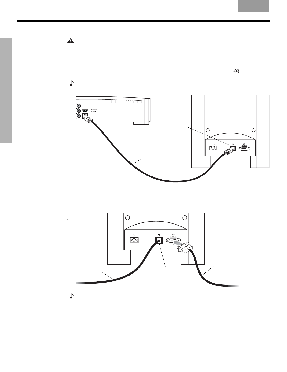
Connecting the Acoustimass module to the media center
Plug one end of the Acoustimass module cable into the
SYSTEM SETUP
Figure 6
Acoustimass module-tomedia center connection
of the media center (Figure 6). Plug the other end of the cable into the input (
rear of the Acoustimass module.
Note:
in one way. Make sure that the arrow on the connector body faces up when plugging in the cable.
EnglishFrançais Español
Acoustimass Module
jack on the rear
) jack on the
The jacks for the Acoustimass module cable are keyed so that the cable connectors only plug
Acoustimass
Media center
rear panel
module input
jack
Figure 7
Speaker cable-toAcoustimass module
connection
Acoustimass
module cable
Acoustimass
module rear panel
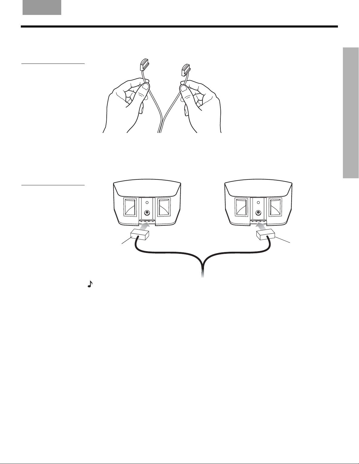
Connecting the speakers to the Acoustimass module
1. Insert the single-plug end of the speaker cable into the SPEAKERS jack on the rear
panel of the Acoustimass module (Figure 7). Tighten both screws on the plug.
Speaker
Acoustimass
module cable
Acoustimass
module input
jack
cable
12
Note: If additional audio cables or longer cables are needed to make these connections, contact
Bose Customer Service. Refer to the list of offices included in the product carton.
6\VWHP6HWXSIP
English FrançaisEspañol
Figure 8
Separating left and right
speaker cords
S
YSTEM SETUP
2. At the other end of the speaker cable, separate the left and right speaker cords as much
as necessary to reach each speaker (Figure 8).
3. Plug the LEFT speaker cable into the rear jack of the left speaker (Figure 9). Plug the
RIGHT speaker cable into the rear jack on the right speaker.
SYSTEM SETUP
Figure 9
Left and right speaker
connections
RIGHT
speaker
cable
LEFT
speaker
cable
Note: Make sure cable connectors are fully inserted and seated firmly in the speaker jacks.
6\VWHP6HWXSIP
13
S
YSTEM SETUP
Figure 10
SYSTEM SETUP
Antenna connections
EnglishFrançais Español
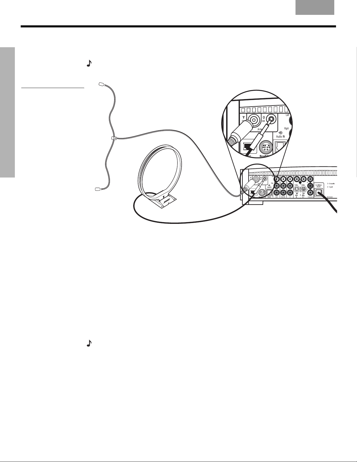
Connecting the supplied antennas
The rear panel of the media center provides jacks for the AM and FM antennas included with
your system (Figure 10). Unwind the wires for each antenna to provide the best reception.
Note: An outdoor antenna may be used in place of the supplied indoor antennas. To add an outdoor antenna, consult a qualified installer. Follow all safety instructions supplied with the antenna.
FM dipole
antenna
Media center
AM loop antenna
FM antenna
Plug the FM antenna into the FM jack on the media center rear panel. Spread out the antenna
arms and move them around to establish optimum FM reception. Extend the antenna as far
from the media center and other equipment as possible.
AM antenna
Plug the AM loop antenna into the AM jack on the media center rear panel. Place the antenna
loop at least 20 inches (50 centimeters) away from the media center and at least 4 feet (1.2
meters) away from the Acoustimass
®
module. Experiment with positioning the loop for optimum AM reception. Follow the instructions enclosed with the AM loop antenna to stand it on
the supplied base, or mount it to a wall.
Connecting cable FM radio
Some cable TV providers make FM radio signals available through the cable service to your
home. This connection is made to the external FM jack on the back panel of the media center. To connect to this service, contact your cable TV provider for assistance.
Note:
Make sure that the cable radio installation includes a TV/FM splitter so that only the
FM radio band, not the cable TV band, is received by the media center. If necessary, contact your
cable company.
14
6\VWHP6HWXSIP
English FrançaisEspañol
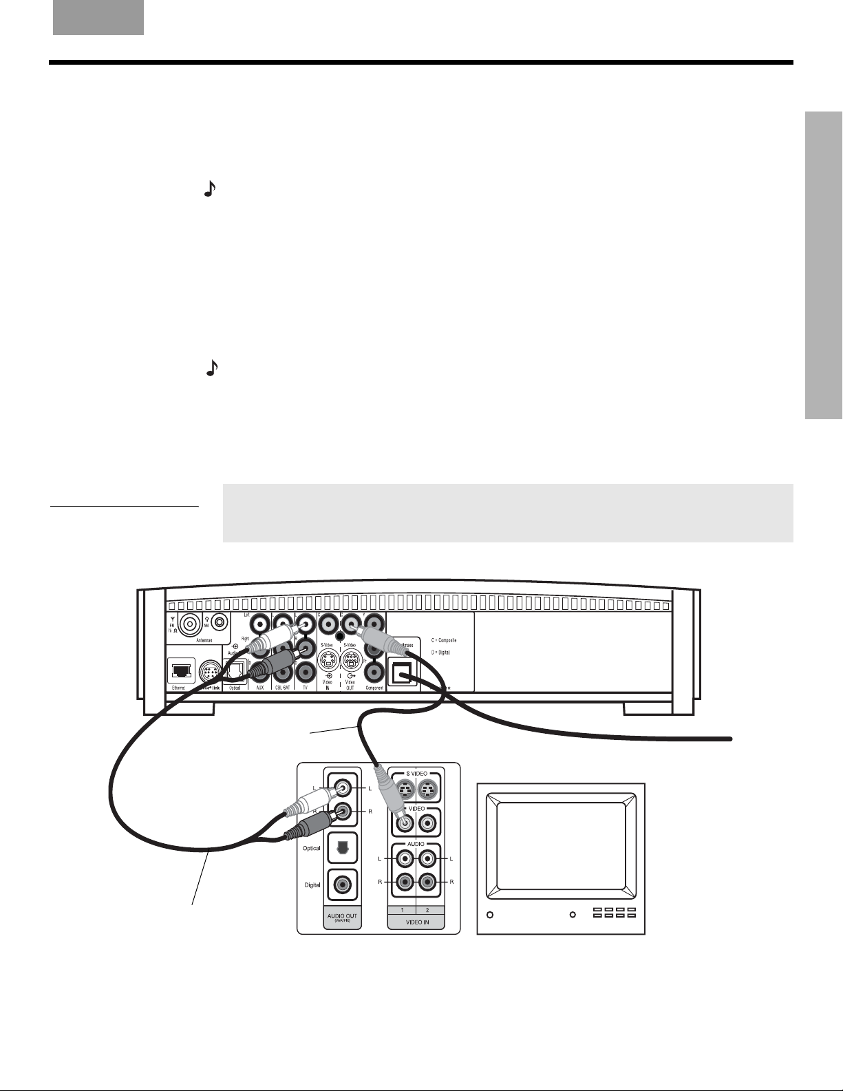
Connecting your TV to the media center
S
YSTEM SETUP
Figure 11
TV (composite video)-tomedia center connections
If you want to use the 3•2•1 GSX system with both a TV and a VCR, skip this section
and go to “Connecting your TV and VCR to the media center” on page 16.
Making audio connections
Note: If your TV does not have audio output jacks, see “Option B: TV (NO audio output jacks) +
VCR + media center” on page 17. Otherwise, continue.
1. Connect one end of the supplied stereo cable to the TV Audio IN jacks on the rear panel
of the media center (Figure 11). Insert the white RCA plug into the TV white L jack. Insert
the red RCA plug into the TV red R jack.
2. Connect the other end of the stereo cable to the audio output jacks on your TV. Insert the
white RCA plug into the white AUDIO OUT L jack. Insert the red RCA plug into the red
AUDIO OUT R jack.
Making composite video connections
Note: Some older TVs with standard TV cable connectors do not have a composite video or an
S-video input. Such TVs are not compatible with any DVD players and require use of an RF modulator for this connection. RF modulators are available at your local electronics store.
1. Insert one end of the supplied video cable (yellow) to the Video OUT C (composite) jack
on the back of the media center (Figure 11).
2. Insert the other end of the video cable into one of the video input jacks on your TV.
Write the name of the video input jack used on your TV in the box on page 25. After
you turn the system on, you will need to select this video input on your TV in order
to view the 3•2•1
GSX
system video output.
SYSTEM SETUP
Video cable
(yellow connectors)
Stereo cable
(red and white connectors)
Media center rear panel
TV connector panel
TV
*
6\VWHP6HWXSIP
15
S
YSTEM SETUP
Connecting your TV and VCR to the media center
There are two options for connecting your TV and VCR to the media center.
•
Option A:
TV with audio output jacks+VCR
•
Option B:
TV without audio output jacks+VCR
Before proceeding, check your TV for audio output jacks.
SYSTEM SETUP
Option A: TV (with audio output jacks) + VCR + media center
If your TV has audio output jacks, you can directly route the TV audio to the 3•2•1 GSX home
entertainment system (Figure 12).
1. Connect one end of the supplied stereo cable to the TV Audio IN jacks on the rear panel
of the media center. Insert the white RCA plug into the TV white L jack. Insert the red
RCA plug into the TV red R jack.
2. Connect the other end of the stereo cable to the audio output jacks on your TV. Insert the
white RCA plug into the white AUDIO OUT L jack. Insert the red RCA plug into the red
AUDIO OUT R jack.
3. Insert one end of the supplied video cable (yellow) to the Video OUT C (composite) jack
on the back of the media center. Insert the other end of the video cable into one of the
video input jacks on your TV.
EnglishFrançais Español
Figure 12
Option A connections
(red and white connectors)
Stereo cable
Write the name of the video input jack used on your TV in the box on page 25. After
you turn the system on, you will need to select this video input on your TV in order
to view the 3•2•1
GSX
system video output.
Video cable
(yellow connectors)
TV connector
panel
Cable/satellite box
(if applicable)
Cable
service
Cable
service
VCR
TV
16
*
6\VWHP6HWXSIP

English FrançaisEspañol
S
YSTEM SETUP
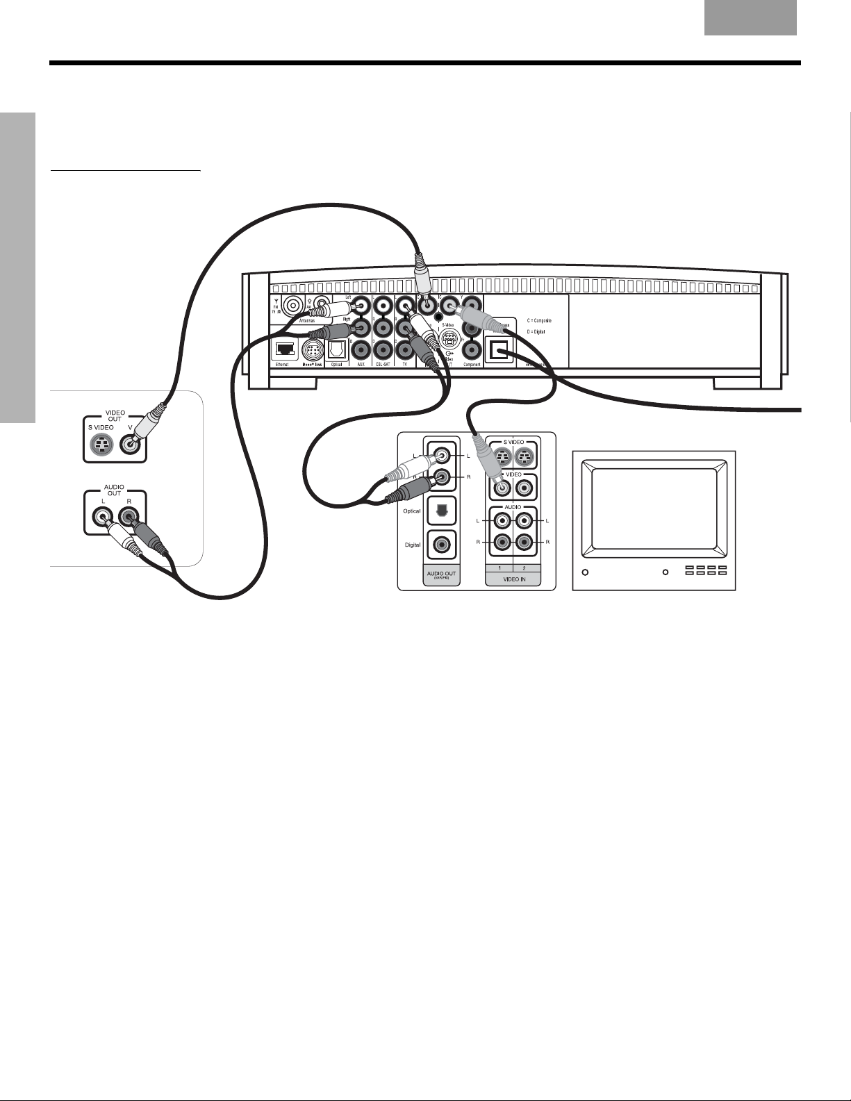
Option B: TV (NO audio output jacks) + VCR + media center
If your TV does not have audio output jacks, you will need to feed audio to the 3•2•1 GSX
home entertainment system through a secondary source, such as a VCR. To do this, you will
need one additional video cable, which can be purchased at your local electronics store.
1. Connect one end of the supplied stereo cable to the AUX Audio IN jacks on the rear
panel of the media center (Figure 13). Insert the white RCA plug into the AUX white L
jack. Insert the red RCA plug into the AUX red R jack.
2. Connect the other end of the stereo cable to the AUDIO OUT jacks on your VCR. Insert
the white RCA plug into the white AUDIO OUT L jack. Insert the red RCA plug into the
red AUDIO OUT R jack.
3. Insert one end of the supplied video cable (yellow) into the VIDEO OUT jack on the
back of your VCR. Insert the other end of the cable into the Video IN C (composite) jack
on the back of the media center.
4. Insert one end of the second video cable (yellow) into the Video OUT C (composite) jack
on the back of the media center. Insert the other end of the cable into one of the video
input jacks on your TV.
SYSTEM SETUP
Figure 13
Option B connections
Write the name of the video input jack used on your TV in the box on page 25. After
you turn the system on, you will need to select this video input on your TV in order
to view the 3•2•1
Media center rear panel
Stereo cable
(red and white connectors)
IMPORTANT
If you connected your TV and VCR this way, you
will need to turn on your VCR and select the
AUX source on the 3•2•1 remote to hear sound
from TV programs.
GSX
system video output.
Video cables
(yellow connector)
TV connection panel
Cable/satellite box
VCR
TV
Cable
service
VCR
connection
panel
Cable
service
6\VWHP6HWXSIP
17
S
YSTEM SETUP
SYSTEM SETUP
Advanced setup options
EnglishFrançais Español
VCR considerations
• Some combination TV/VCR units may not work with 3•2•1 GSX home entertainment sys-
tems. Please refer to your TV/VCR owner’s manual for information.
• A stereo VCR is required for optimal sound performance. If your VCR has only one audio
output, you have a mono VCR. You will need a Y-adapter cable (available at electronics
stores) to connect audio to the media center. For this setup, you will need to select “Mono
decoding” (see “TV, CBL-SAT, and AUX settings menu” on page 52) so your 3•2•1 GSX
system will simulate surround sound effects from a mono source. Otherwise, you will hear
mono sound from both speakers.
The 3•2•1 GSX home entertainment system provides connections for producing higher quality video and audio. The following describes how to use these connections.
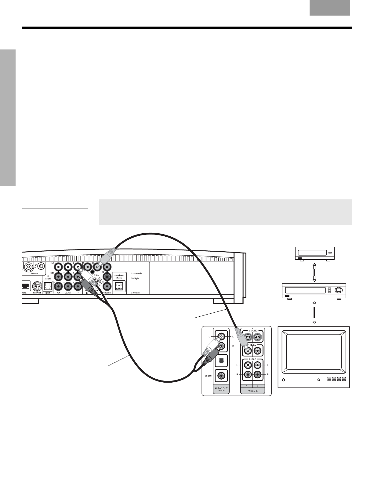
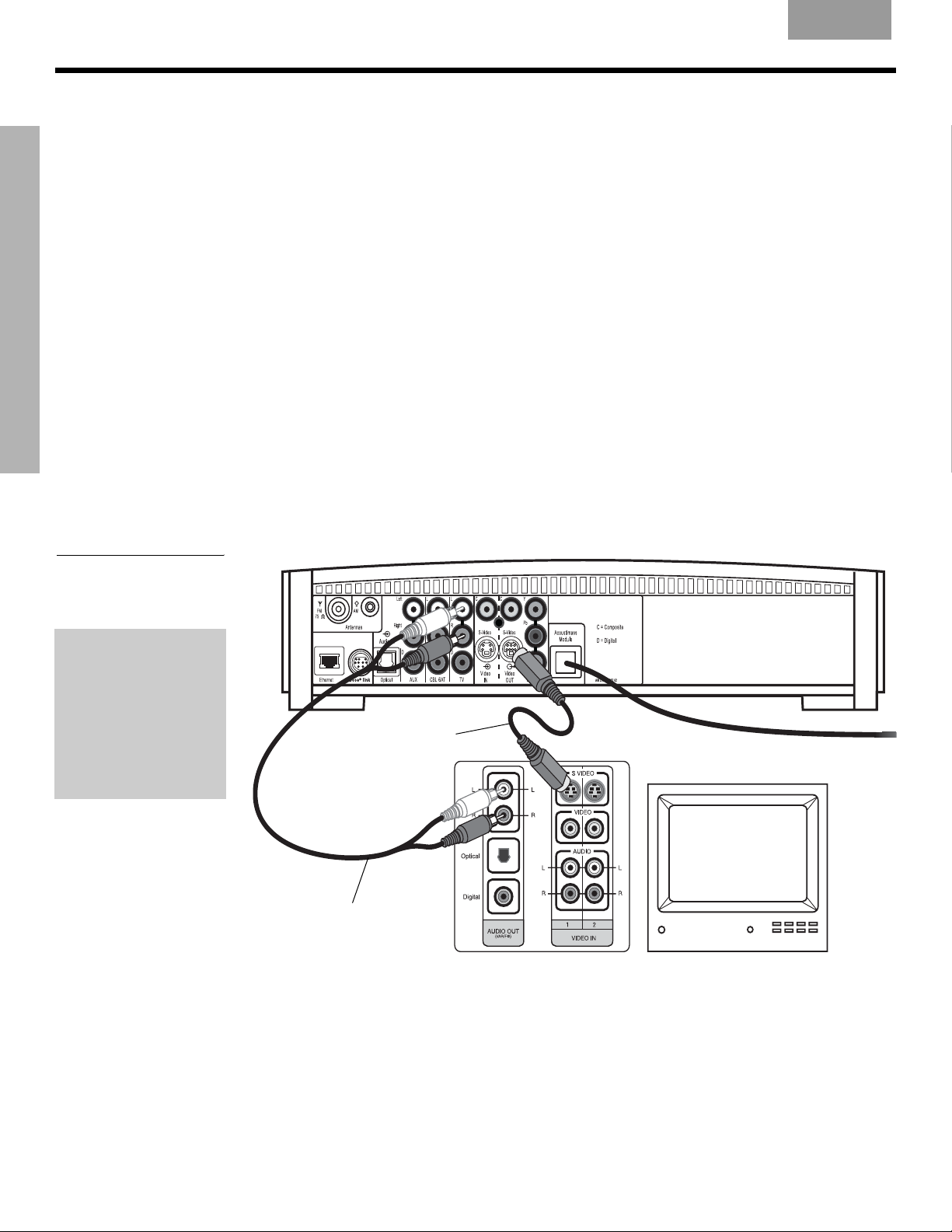
Making S-video connections (higher quality video)
An S-video input jack, provided on many TVs, delivers a higher quality TV picture than the
composite video output connection shown in Figure 11. For this connection you will need an
S-video cable which can be purchased from your Bose dealer or a local electronics retailer.
1. Insert one end of the S-video cable into the S-Video OUT jack on the media
center (Figure 14).
2. Insert the other end of the S-video cable into the S-VIDEO IN jack on your TV.
Figure 14
TV (S-video)-to-media
center connections
IMPORTANT
If you use S-video to
connect your TV to the
media center, you
must also use S-video
to connect all other
devices (such as a
cable box and VCR) to
the media center.
Media center rear panel
S-video cable
TV connector panel
TV
Stereo cable
(red and white connectors)
18
6\VWHP6HWXSIP
English FrançaisEspañol
S
YSTEM SETUP
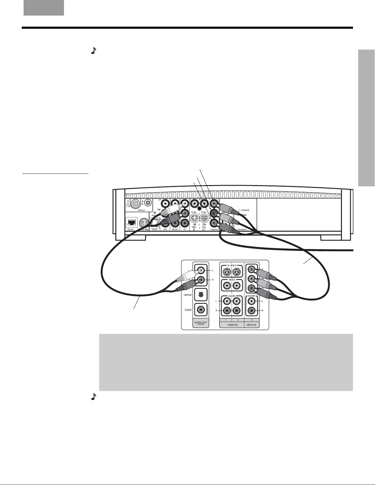
Making component video connections (highest quality video)
Note: Component video connections are required in order to use the progressive scan (NTSC
only) feature of your 3•2•1 GSX system. Your TV must also support this feature. To turn on the
progressive scan feature, see “Video options” on page 59.
For the highest quality video from DVDs, you may want to use a component video connection
between the media center and the TV. To do so, your TV must provide component video jacks
(typically labelled Y, Pb, and Pr). Refer to your TV owner’s guide for more information.
To make component video connections you will need a component video cable that is long
enough to reach from the rear of the media center to your TV (Figure 15). If the cable is not
supplied with your TV, you can purchase it separately.
1. On the media center rear panel, plug one end of the component video cable into the
Component Y, Pb, and Pr video output jacks (Figure 15). Be sure to match the color of
the plug with the color of the jack.
2. Plug the other end of the component video cable into the corresponding (color or letter
code) component video jack on the back of your TV.
SYSTEM SETUP
Figure 15
Component video
TV-to-media center
connections
Component video output jacks:
Stereo cable
(red and white connectors)
Y (green)
Pb (blue)
Pr (red)
Media center rear panel
Component
video cable
TV connector
panel (example)
IMPORTANT FOR COMPONENT VIDEO USERS
Input signals received by the C (Composite) or
the
Component
S-Video IN
video
OUT
jacks. If you connect an external video device to the C or
jack, you must also connect the C or
S-Video IN
S-Video OUT
jacks are not passed through to
jack on the media center to
the respective video input jack on your TV. To view the external video input on your TV, you
will need to select the TV video input used for that device. To view the onscreen menus of the
3•2•1
GSX
system, you will need to switch back to the TV’s component video input.
Note: For more information, or to purchase the video cables, contact your local electronics store
or authorized Bose dealer.
19
6\VWHP6HWXSIP
S
YSTEM SETUP
SYSTEM SETUP
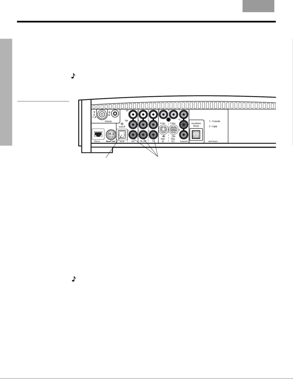
Figure 16
Media center digital audio
input jacks
EnglishFrançais Español
Connecting digital audio devices
Some audio devices feature a digital audio output for optimum sound performance. Use an
optical digital cable or a coaxial digital cable, as appropriate, to connect this output to the
digital input on the media center. You can purchase the required cables at a local electronics
store.
On the media center rear panel, an optical digital cable connects to the OPTICAL jack. A
coaxial cable connects to the audio input jacks labeled D.
Note:
Before you can benefit from the optical connection, you will need to assign the optical
connector to the audio source in the system settings menu. See “Media center options” on
page 60.
Optical digital
audio input
Coaxial digital
audio inputs
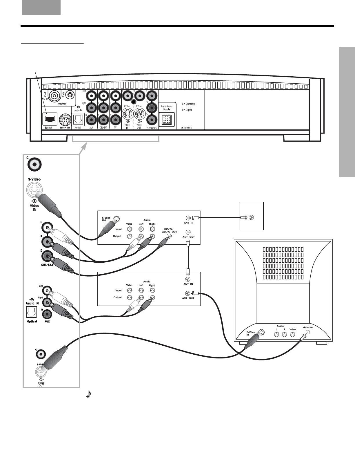
Connecting your cable/satellite box, TV, and VCR to the media center
The 3•2•1 GSX home entertainment system provides flexibility for you to add up to three
external audio devices, including your TV, directly to the media center.
Figure 17 shows you an advanced setup using a TV, VCR and cable/satellite box. In this
setup, please notice the following:
• S-video connections are used to deliver the cable/satellite signal to the media center.
Therefore, the media center output video is sent to the TV also through an S-video
connection.
• Analog and digital coaxial audio connections are shown for the cable/satellite box. As an
option, you may use an optical digital connection. However, before you can benefit from the
optical connection, you will need to assign the optical connector to the cable/satellite box
audio source in the system settings menu. See “Media center options” on page 60.
• When connecting an audio device to the media center jacks, remember to match the red
jack to the right channel (R) and the white (or black) jack to the left channel (L).
• For further details on making the video connections between your VCR and TV, refer to the
manuals for these video devices.
Note:
The recommendations contained in this owner’s guide are basic suggestions for connecting external devices to the 3•2•1 GSX system. Instructions and terminology pertinent to these
external devices may vary, depending on the manufacturer. Consult the owner’s guide that came
with the device for clarification on setup and usage before making any connections.
20
6\VWHP6HWXSIP
English FrançaisEspañol
Figure 17
Advanced setup example:
TV, VCR and cable/satellite
box
S
YSTEM SETUP
SYSTEM SETUP
For future use only.
CBL-SAT
S-video
Media center
Cable/satellite
(CBL-SAT)
service
Cable/satellite
CBL-SAT analog
audio
CBL-SAT
digital audio
CBL-SAT
signal to
VCR
VCR
TV
CBL-SAT
VCR analog audio
Media center’s
S-video output
to TV
signal to
TV
Note: For more information on advanced connections, refer to the DVD setup disc that came
with your 3•2•1 GSX home entertainment system.
6\VWHP6HWXSIP
21
S
YSTEM SETUP
Figure 18
Game console connections
SYSTEM SETUP
Game console
connection panel
EnglishFrançais Español
Connecting a game console
Connect the audio output of a game console to the AUX Left and Right input jacks. Connect the video output of the game console to the C (composite) Video IN jack.
Media center
TV connection panel
IMPORTANT
If you connected your game console this way, you will need
to select the AUX source on the 3•2•1 remote in order to
hear sound from the game console.
22
6\VWHP6HWXSIP
English FrançaisEspañol
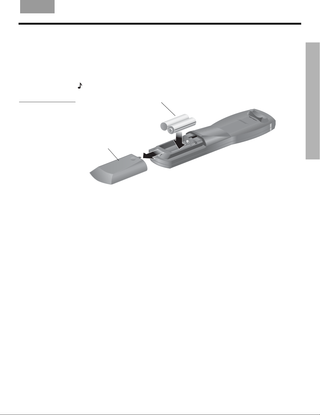
Installing the remote control batteries
S
YSTEM SETUP
Figure 19
Installing the batteries
1. On the back of the remote, slide open the battery compartment (Figure 19).
2. Insert the two supplied AA (IEC-R6) 1.5V batteries, or their equivalent, as shown. Match
the plus (+) and minus (–) marked on the batteries with the plus (+) and minus (–) inside
the battery compartment.
3. Slide the battery compartment cover back into place.
Note:
R
eplace the batteries when the remote control stops operating or its range seems reduced.
(2) AA batteries (IEC R6)
+
Battery
compartment
cover
+
SYSTEM SETUP
6\VWHP6HWXSIP
23
S
YSTEM SETUP
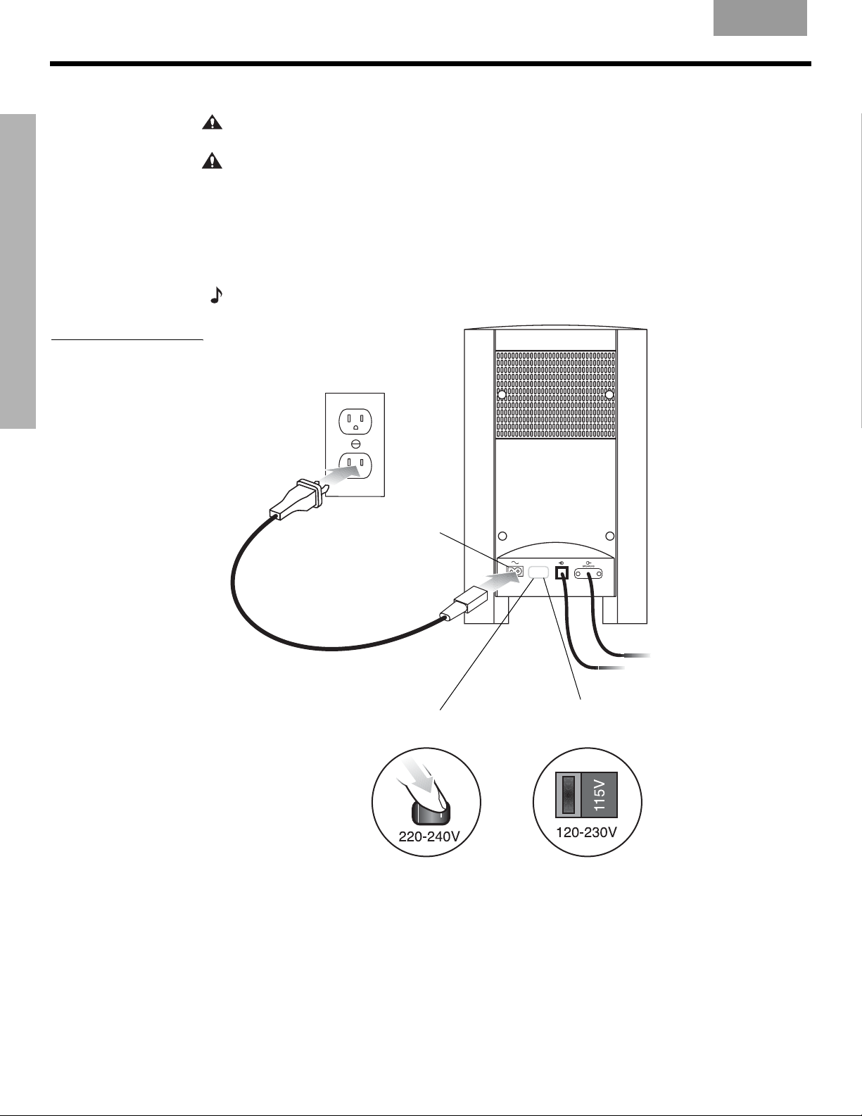
Connecting the power cord
CAUTION: Do not plug the Acoustimass® module into an AC power (mains) outlet until all the
components are connected.
CAUTION:
of the Acoustimass module to the appropriate voltage for your area (115V or 230V) before
connecting to power. If you are not sure about the proper voltage for your area, consult your
SYSTEM SETUP
Figure 20
Connecting to power
local electrical authorities.
1. Insert the small connector end of the power cord into the AC INPUT connector on the
Acoustimass module (Figure 20).
2. Insert the large end of the cord into an AC power (mains) outlet.
Note:
EnglishFrançais Español
For dual voltage models only, be sure to set the dual voltage switch on the back
On 220-240V models only, turn the Acoustimass module POWER switch to on (l).
Note: Provided
only on 220-240V
rated systems
AC input
jack
AC power
switch
115/230V
selection
switch
Note: Provided
only on 115/230V
dual voltage rated
systems
24
6\VWHP6HWXSIP
English FrançaisEspañol
Verifying your system setup
S
YSTEM SETUP
1. Check the following before you continue:
• All cables are connected for the setup you chose.
• The batteries were installed in the remote control.
• The power cord was installed and plugged into a live AC receptacle.
2. Turn on your TV. Use the remote control that came with your TV.
3. Using your TV remote, select the video input on your TV that connects to the
video output of the media center.
Name TV video input used:
• The method of selecting the right video input depends on your TV. Refer to your TV
owner’s guide for help.
4. Turn off the TV speakers.
• Refer to your TV owner’s guide for help.
• If your TV does not have an option to turn off the internal speakers, you may need to
adjust both the 3•2•1 GSX system volume and your TV volume until you find a level
that produces the desired sound.
• In some TVs, when the internal speakers are turned off, you may need to raise the TV’s
volume level by 75% to 100% in order to hear audio from the 3•2•1 GSX home entertainment system. See your TV owner’s guide for help.
5. Turn on your 3•2•1 GSX system.
SYSTEM SETUP
• Point the 3•2•1 GSX remote control at the media center and press On-Off
6. Play the 3•2•1 GSX setup DVD.
• Press Eject on the media center control panel.
• Insert the DVD setup disc into the disc tray.
• Press Eject again to close the tray. The DVD will automatically begin to play. If it does
not, press the play button (
Be sure to play the Setup DVD, included in the carton with your system, as soon as all the
Note:
connections are completed. This will help you verify the connections you have made and confirm
proper sound performance.
).
.
6\VWHP6HWXSIP
25
SYSTEM CONTROLS AND INDICATORS
Remote control
EnglishFrançais Español
Remote
status
LED
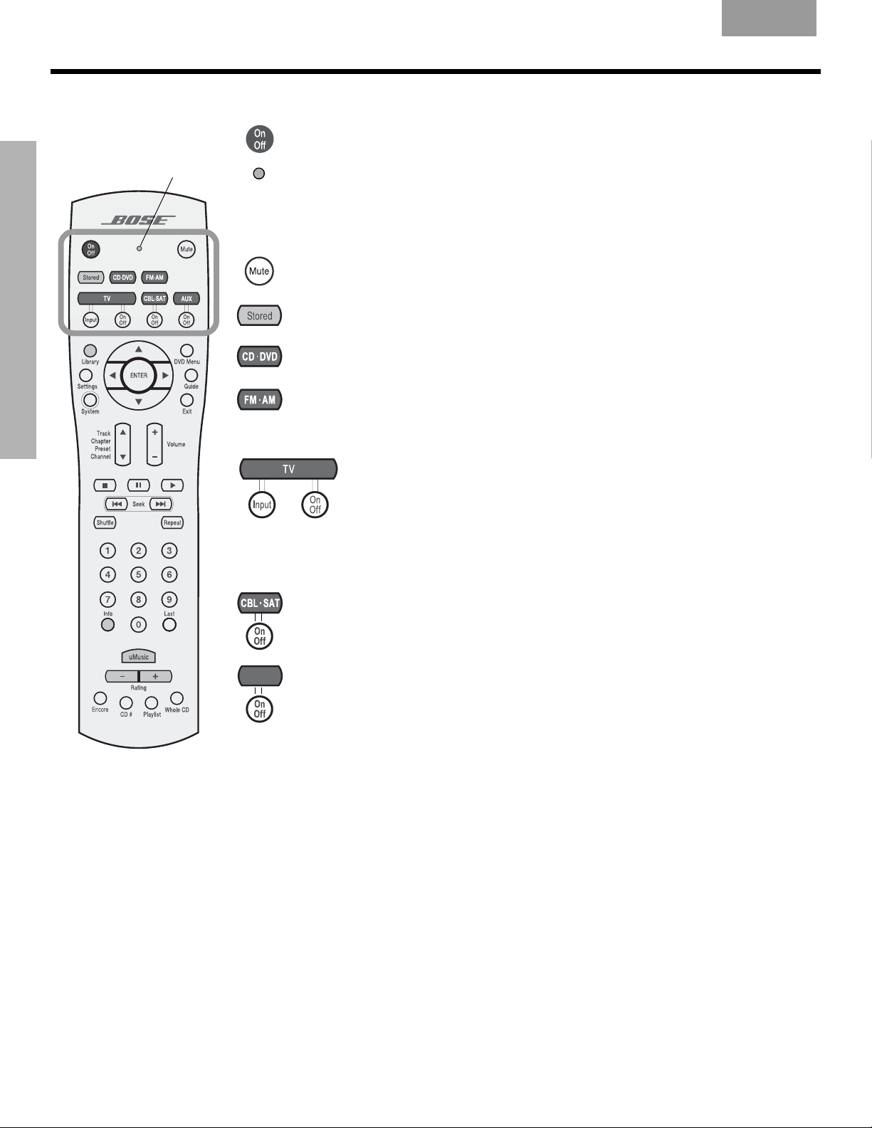
SYSTEM CONTROLS AND INDICATORS
Turns the system on or off.
Status LED:
• Off (unlit) during normal operation.
• On during the process of setting up the remote to control other equipment such
as your TV or VCR.
Silences or restores the sound from the current source.
Selects the Stored CD source and turns the system on to the last-selected
uMusic™ intelligent playback system play mode.
Selects the built-in CD/DVD player and turns the system on.
• Selects the built-in tuner and turns the system on to the previously selected
FM/AM station.
• Switches between FM and AM when the tuner is selected.
TV: Selects the TV sound source and turns your system on.
Input: Changes the external input to your TV. For example, your TV
might have two external inputs where one is connected to your cable
box and the other to your VCR. Pressing this button alternates between
the cable box and the VCR.*
On/Off: Turns your TV on and off.*
CBL-SAT: Selects the CBL-SAT sound source and turns your system on.
On/Off: Turns your cable/satellite box on or off.*
AUX: Selects the AUX sound source and turns your system on.
AUXAUX
On/Off: Turns a VCR or PVR that is connected to the AUX jack on or off.*
*Requires special remote settings. See “Setting up your remote to control other audio/video devices”
on page 30.
26
&RQWUROV$QG,QGLFDWRUVIP
English FrançaisEspañol
Remote control – cont.
S
YSTEM CONTROLS AND INDICATORS
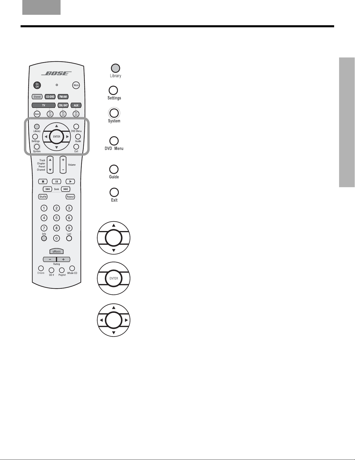
Enters the library of stored CD tracks.
Displays the Settings menu for the current source on your TV screen or
media center display.
Displays the System menu on your TV screen.
• Displays the DVD menu of the currently loaded DVD disc on your TV
screen.
• Displays the main menu of a cable/satellite box, VCR, or PVR on your TV
screen (if supported).*
Displays the TV program guide (if supported) on your TV screen.
SYSTEM CONTROLS AND INDICATORS
• Removes the Settings menu, System menu, or Library menu from your
TV screen.
• Removes the TV program guide (if supported) from your TV screen or
media center display.
• Tunes the FM or AM radio to the next higher or lower frequency.
• Selects the next item, up or down, in menus.
Confirms a menu selection or introduces the next level of menu options.
Moves up, down, left, or right in onscreen menus and media center
displays.
*Requires special remote settings. See “Setting up your remote to control other audio/video devices” on
page 30.
&RQWUROV$QG,QGLFDWRUVIP
27
S
YSTEM CONTROLS AND INDICATORS
Remote control – cont.
SYSTEM CONTROLS AND INDICATORS
EnglishFrançais Español
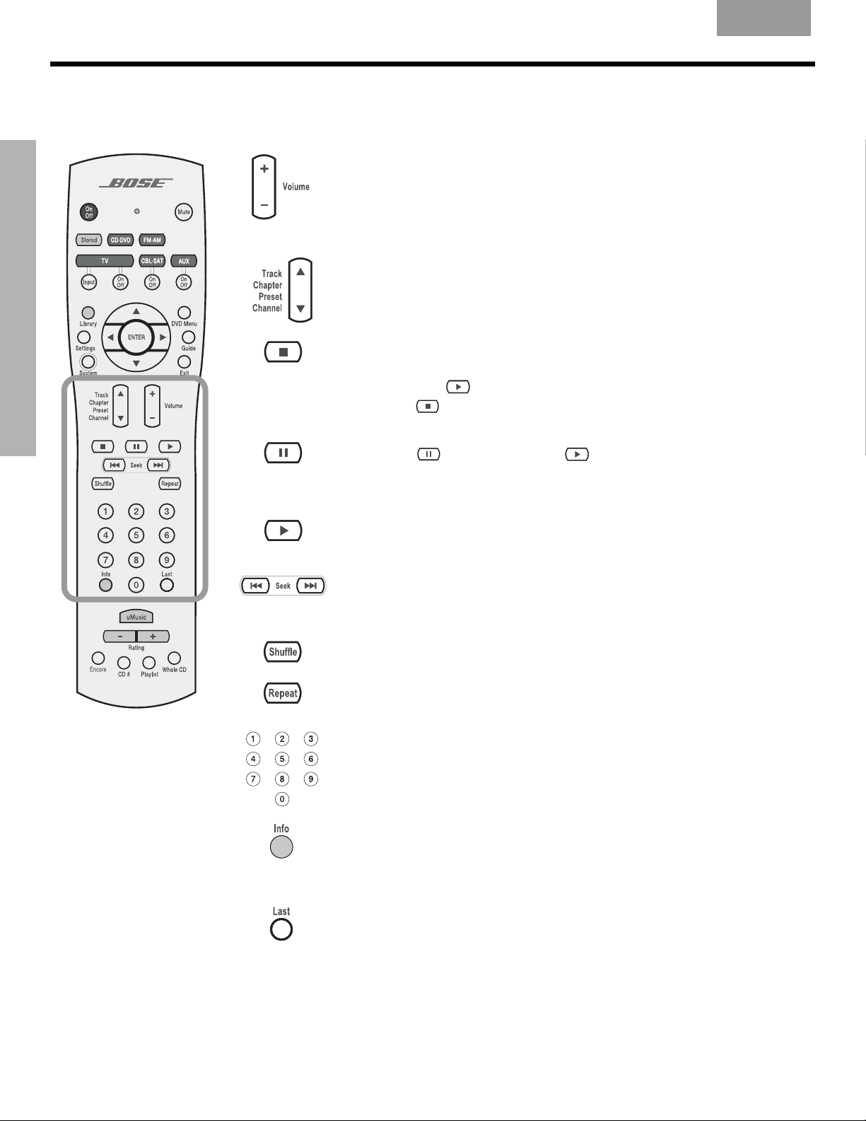
• Raises or lowers the volume of the current source.
• Pressing + restores muted sound from the current source.
• Pressing – lowers the volume of the current source, but does not restore
muted sound.
Skips to the next or previous CD track, DVD chapter, radio station preset,
or TV channel (if the remote is set up to control your TV).
• Stops the disc player.
•
For DVDs only
tion. Pressing
Pressing
, the disc stops and the system saves the DVD play posi-
continues the DVD from the saved play position.
twice for a disc in play returns to the beginning of the disc.
• Pauses a currently playing disc.
• Pressing
• After 20 minutes of no user interaction, the disc player stops and returns
to the beginning of the disc to wait for the next command.
Starts the disc player.
• Skips backward or forward through CD tracks.
• Skips backward or forward through DVD chapters.
• Seeks backward or forward to the next strongest radio station.
Plays audio CD tracks in random order. Press again to cancel.
Repeats a CD, CD track, DVD chapter, or DVD title depending on the
selected source. Press again to change the repeat mode.
• Selects a CD track, DVD chapter, radio station preset, or TV channel.
• Selects a uMusic preset for the Stored source.
• Allows numerical selection for some menu options.
• Displays or dismisses a cable/satellite information window, if supported.
• If playing an MP3 CD, displays or dismisses artist and title information
on the media center display panel.
• Displays information about the stored track that is playing.
again (or pressing ) resumes play of a paused disc.
28
Skips to the previous TV channel (if supported by your TV or
cable/satellite box).
&RQWUROV$QG,QGLFDWRUVIP
English FrançaisEspañol
Remote control – cont.
S
YSTEM CONTROLS AND INDICATORS
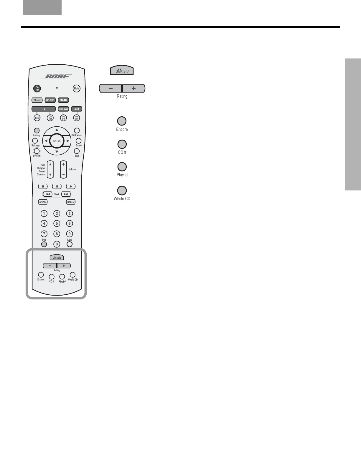
Selects the uMusic™ intelligent playback system for playing stored
music. Overrides any other stored music play mode.
• Applies a negative (–) or positive (+) rating to the stored track
currently playing.
•Pressing
•Pressing
Selects and plays stored music that most closely matches the style of
the current track.
Plays the tracks from a CD selected by its number in the uMusic
system.
Plays all the tracks, if any, assigned to the playlist. Can be used with
other play mode options, like Encore.
–
immediately selects a new track.
+
continues playing the current track.
SYSTEM CONTROLS AND INDICATORS
Skips from the track most recently playing to the first track on the CD
of origin and plays that CD from beginning to end.
&RQWUROV$QG,QGLFDWRUVIP
29
S
YSTEM CONTROLS AND INDICATORS
Setting up your remote to control other audio/video devices
Your remote can be set up to control other audio/video devices such as a TV, VCR, PVR or
cable/satellite box by entering a device code while in the setup mode.
• If you know the device code, follow the instructions under the heading, “Direct
entry of a device code” below. Device codes are listed in the back section of this
owner’s guide and in the System menus under Remote Control options.
• If you can’t find the device code and want to search the system for it, see
“Searching for a device code” on page 31.
• If you want to verify the device code you have entered for an audio/video device,
see “Verifying an entered device code” on page 33.
• If you want to return to a previous device assignment, press and hold the TV button
until the remote LED is lit (about 5 seconds). On the remote keypad, enter 977.
• If you want to wipe out all assigned codes, press and hold the TV button until the
remote LED is lit (about 5 seconds). On the remote keypad, enter 981.
SYSTEM CONTROLS AND INDICATORS
Note: More than one code may work with your particular brand of product. If you notice a lack of
response or limited functionality after setting up the remote, try a different code.
Note: The remote status LED flashes rapidly eight times if you press an invalid key, or enter an
unavailable device code. Wait seven seconds for the error to clear and start again.
EnglishFrançais Español
Direct entry of a device code
Device codes can be found at the back of this owner’s guide or in the System menu under
Remote Control options. If you know the device code, you can do the following:
To set up the remote to control your TV
1. Turn on both the 3•2•1 GSX system and your TV.
2. Press and hold the TV button until the remote LED is lit (about five seconds).
3. On the remote keypad, enter the four-digit device code for your TV. The LED will turn off
temporarily as you press each key.
4. Check that the LED turns off after the code is entered. If the LED blinks, the code is
invalid. Try again.
5. Point the remote at your TV and press the TV On-Off button. If your TV does not
respond, go back to step 2 and try other codes. If you are still unsuccessful, see
“Searching for a device code” on page 31.
Note: $IWHUSURJUDPPLQJ\RXUUHPRWHWRFRQWUROH[WHUQDODXGLRYLGHRGHYLFHVIURPWKH6\VWHP
PHQXSUHVVWKH6\VWHPEXWWRQRQFHWRFRQWLQXHQDYLJDWLQJWKH6\VWHPPHQX
To set up the remote to control your cable/satellite box
1. Turn on both the 3•2•1 GSX system and your cable/satellite box.
30
2. Press and hold the CBL-SAT button until the remote LED is lit (about five seconds).
3. On the remote keypad, enter the four-digit device code for your cable/satellite box. The
LED will turn off temporarily as you press each key.
&RQWUROV$QG,QGLFDWRUVIP
 Loading...