

Page 1
Owner’s Guide
Page 2
Safety Information
CAUTION
VIS
WARNING: To reduce the risk of fire or electric shock, do not expose the system to rain or moisture.
WARNING:
This apparatus shall not be exposed to dripping or splashing, and objects filled with liquids,
such as vases, shall not be placed on the apparatus. As with any electronic products, use care not to spill
liquids in any part of the system. Liquids can cause a failure and/or a fire hazard.
CAUTION
RISK OF ELECTRICAL SHOCK
DO NOT OPEN
CAUTION: TO REDUCE THE RISK OF ELECTRIC SHOCK,
DO NOT REMOVE COVER (OR BACK).
NO USER-SERVICABLE PARTS INSIDE.
REFER SERVICING TO QUALIFIED PERSONNEL.
RISQUE DE CHOC ÉLECTRIQUE
ATTENTION : POUR RÉDUIRE LE RISQUE DE DÉCHARGE
ÉLECTRIQUE, NE RETIREZ PAS LE COUVERCLE (OU
L’ARRIÈRE). IL NE SE TROUVE ÀL’INTÉRIEURAUCUNE
PIÈCE POUVANT ÊTRE RÉPARÉE PAR L’USAGER.
S’ADRESSER À UN RÉPARATEUR COMPÉTENT.
AVIS
NE PAS OUVRIR
The CAUTION marks shown here are located on the bottom of your 3•2•1 Series II home entertainment
system media center and the rear panel of the Acoustimass module:
The lightning flash with arrowhead symbol, within an equilateral triangle, alerts the user to the
presence of uninsulated dangerous voltage within the system enclosure that may be of sufficient magnitude to constitute a risk of electric shock.
The exclamation point within an equilateral triangle alerts the user to the presence of important
operating and maintenance instructions in this owner’s guide.
CAUTION: To prevent electric shock, match wide blade of plug to wide slot, insert fully.
CAUTION:
No naked flame sources, such as lighted candles, should be placed on the apparatus.
Class 1 laser product
The DVD player contained within the media center is classified as a CLASS 1
LASER PRODUCT according to EN60825-1:1994 + A11. The CLASS 1
LASER PRODUCT label is located on the bottom of the media center.
CLASS 1 LASER PRODUCT
KLASSE 1 LASER PRODUKT
LUOKAN 1 LASER LAITE
KLASS 1 LASER APPARAT
CAUTION: Use of controls or adjustments or performance of procedures other than those specified herein may result in hazardous radiation exposure. The DVD player should not be adjusted or
repaired by anyone except properly qualified service personnel.
Class B emissions limits
This Class B digital apparatus meets all requirements of the Canadian Interference-Causing Equipment
Regulations.
Batteries
Please dispose of used batteries properly, following any local regulations. Do not incinerate.
Additional safety information
See the additional instructions on the
Important Safety Information
sheet enclosed in the shipping carton.
Please read this owner’s guide
Please take the time to follow this owner’s guide carefully. It will help you set up and operate your system properly, and enjoy all of its advanced features. Save your owner’s guide for future reference.
2
Page 3

Contents
Contents
Introduction . . . . . . . . . . . . . . . . . . . . . . . . . . . . . . . . . . . . . . . . . . . . . . . . . . . . . . . . . . . . . . . . . . . 5
Before you begin . . . . . . . . . . . . . . . . . . . . . . . . . . . . . . . . . . . . . . . . . . . . . . . . . . . . . . . . . . . 5
Selecting compatible discs . . . . . . . . . . . . . . . . . . . . . . . . . . . . . . . . . . . . . . . . . . . . . . . . 5
Check for region code compatibility . . . . . . . . . . . . . . . . . . . . . . . . . . . . . . . . . . . . . . . . . 5
MP3 compatibility . . . . . . . . . . . . . . . . . . . . . . . . . . . . . . . . . . . . . . . . . . . . . . . . . . . . . . . 5
Glossary of terms . . . . . . . . . . . . . . . . . . . . . . . . . . . . . . . . . . . . . . . . . . . . . . . . . . . . . . . . . . . 6
Limited warranty . . . . . . . . . . . . . . . . . . . . . . . . . . . . . . . . . . . . . . . . . . . . . . . . . . . . . . . . . . . . 7
For your records . . . . . . . . . . . . . . . . . . . . . . . . . . . . . . . . . . . . . . . . . . . . . . . . . . . . . . . . . . . . 7
System Setup . . . . . . . . . . . . . . . . . . . . . . . . . . . . . . . . . . . . . . . . . . . . . . . . . . . . . . . . . . . . . . . . . 8
Unpacking . . . . . . . . . . . . . . . . . . . . . . . . . . . . . . . . . . . . . . . . . . . . . . . . . . . . . . . . . . . . . . . . 8
Selecting locations for your 3•2•1 Series II system components . . . . . . . . . . . . . . . . . . . . . . 9
Placing the media center . . . . . . . . . . . . . . . . . . . . . . . . . . . . . . . . . . . . . . . . . . . . . . . . . . 9
Placing the speakers . . . . . . . . . . . . . . . . . . . . . . . . . . . . . . . . . . . . . . . . . . . . . . . . . . . . . 10
Placing the Acoustimass
Making system connections . . . . . . . . . . . . . . . . . . . . . . . . . . . . . . . . . . . . . . . . . . . . . . . . . . . 12
Connecting the Acoustimass module to the media center . . . . . . . . . . . . . . . . . . . . . . . . 12
Connecting the speakers to the Acoustimass module . . . . . . . . . . . . . . . . . . . . . . . . . . . 12
Connecting the supplied antennas . . . . . . . . . . . . . . . . . . . . . . . . . . . . . . . . . . . . . . . . . . 14
Connecting cable FM radio . . . . . . . . . . . . . . . . . . . . . . . . . . . . . . . . . . . . . . . . . . . . . . . . 14
Connecting your TV to the media center . . . . . . . . . . . . . . . . . . . . . . . . . . . . . . . . . . . . . . . . . 15
Making audio connections . . . . . . . . . . . . . . . . . . . . . . . . . . . . . . . . . . . . . . . . . . . . . . . . . 15
Making composite video connections . . . . . . . . . . . . . . . . . . . . . . . . . . . . . . . . . . . . . . . . 15
Connecting your TV and VCR to the media center . . . . . . . . . . . . . . . . . . . . . . . . . . . . . . . . . 16
If your TV has audio output jacks . . . . . . . . . . . . . . . . . . . . . . . . . . . . . . . . . . . . . . . . . . . 16
If your TV does not have audio output jacks . . . . . . . . . . . . . . . . . . . . . . . . . . . . . . . . . . . 17
VCR considerations . . . . . . . . . . . . . . . . . . . . . . . . . . . . . . . . . . . . . . . . . . . . . . . . . . . . . . 18
Advanced setup options . . . . . . . . . . . . . . . . . . . . . . . . . . . . . . . . . . . . . . . . . . . . . . . . . . . . . 18
Making S-video connections (higher quality video) . . . . . . . . . . . . . . . . . . . . . . . . . . . . . . 18
Making component video connections (highest quality video) . . . . . . . . . . . . . . . . . . . . . 19
Connecting digital audio devices . . . . . . . . . . . . . . . . . . . . . . . . . . . . . . . . . . . . . . . . . . . . 20
Connecting your cable/satellite box, TV, and VCR to the media center . . . . . . . . . . . . . . 20
Connecting a game console . . . . . . . . . . . . . . . . . . . . . . . . . . . . . . . . . . . . . . . . . . . . . . . 22
Installing the remote control batteries . . . . . . . . . . . . . . . . . . . . . . . . . . . . . . . . . . . . . . . . . . . 23
Connecting the power cord . . . . . . . . . . . . . . . . . . . . . . . . . . . . . . . . . . . . . . . . . . . . . . . . . . . 24
Checking your system setup . . . . . . . . . . . . . . . . . . . . . . . . . . . . . . . . . . . . . . . . . . . . . . . . . . 25
System Controls and Indicators . . . . . . . . . . . . . . . . . . . . . . . . . . . . . . . . . . . . . . . . . . . . . . . . . . . 26
Remote control . . . . . . . . . . . . . . . . . . . . . . . . . . . . . . . . . . . . . . . . . . . . . . . . . . . . . . . . . . . . . 26
The media center . . . . . . . . . . . . . . . . . . . . . . . . . . . . . . . . . . . . . . . . . . . . . . . . . . . . . . . . . . . 29
Control panel . . . . . . . . . . . . . . . . . . . . . . . . . . . . . . . . . . . . . . . . . . . . . . . . . . . . . . . . . . . 29
Display indicators . . . . . . . . . . . . . . . . . . . . . . . . . . . . . . . . . . . . . . . . . . . . . . . . . . . . . . . . 29
Operation . . . . . . . . . . . . . . . . . . . . . . . . . . . . . . . . . . . . . . . . . . . . . . . . . . . . . . . . . . . . . . . . . . . . 30
Turning your system on and off . . . . . . . . . . . . . . . . . . . . . . . . . . . . . . . . . . . . . . . . . . . . . . . . 30
Playing video DVDs . . . . . . . . . . . . . . . . . . . . . . . . . . . . . . . . . . . . . . . . . . . . . . . . . . . . . . . . . 30
Basic DVD operations . . . . . . . . . . . . . . . . . . . . . . . . . . . . . . . . . . . . . . . . . . . . . . . . . . . . 31
Restricting access to video DVDs . . . . . . . . . . . . . . . . . . . . . . . . . . . . . . . . . . . . . . . . . . . 31
Playing audio CDs . . . . . . . . . . . . . . . . . . . . . . . . . . . . . . . . . . . . . . . . . . . . . . . . . . . . . . . . . . 32
Basic CD operations . . . . . . . . . . . . . . . . . . . . . . . . . . . . . . . . . . . . . . . . . . . . . . . . . . . . . 32
Listening to FM/AM radio . . . . . . . . . . . . . . . . . . . . . . . . . . . . . . . . . . . . . . . . . . . . . . . . . . . . . 33
Tuning to a station . . . . . . . . . . . . . . . . . . . . . . . . . . . . . . . . . . . . . . . . . . . . . . . . . . . . . . . 33
Storing stations as presets . . . . . . . . . . . . . . . . . . . . . . . . . . . . . . . . . . . . . . . . . . . . . . . . 33
Erasing a preset . . . . . . . . . . . . . . . . . . . . . . . . . . . . . . . . . . . . . . . . . . . . . . . . . . . . . . . . . 34
Playing other sources . . . . . . . . . . . . . . . . . . . . . . . . . . . . . . . . . . . . . . . . . . . . . . . . . . . . . . . . 34
Using the sleep timer . . . . . . . . . . . . . . . . . . . . . . . . . . . . . . . . . . . . . . . . . . . . . . . . . . . . . . . . 34
®
module . . . . . . . . . . . . . . . . . . . . . . . . . . . . . . . . . . . . . . . . . . . 11
Controlling Other Audio Devices . . . . . . . . . . . . . . . . . . . . . . . . . . . . . . . . . . . . . . . . . . . . . . . . . . . 35
Setting up your remote to control other audio/video devices . . . . . . . . . . . . . . . . . . . . . . . . . 35
Direct entry of a device code . . . . . . . . . . . . . . . . . . . . . . . . . . . . . . . . . . . . . . . . . . . . . . . 35
Searching for a device code . . . . . . . . . . . . . . . . . . . . . . . . . . . . . . . . . . . . . . . . . . . . . . . 36
Verifying an entered device code . . . . . . . . . . . . . . . . . . . . . . . . . . . . . . . . . . . . . . . . . . . . 38
Changing channel selection control . . . . . . . . . . . . . . . . . . . . . . . . . . . . . . . . . . . . . . . . . . . . . 38
3
Page 4

Contents
Changing Source Settings . . . . . . . . . . . . . . . . . . . . . . . . . . . . . . . . . . . . . . . . . . . . . . . . . . . . . . . 39
Using the settings menus . . . . . . . . . . . . . . . . . . . . . . . . . . . . . . . . . . . . . . . . . . . . . . . . . . . . . 39
To view the settings menus . . . . . . . . . . . . . . . . . . . . . . . . . . . . . . . . . . . . . . . . . . . . . . . . 39
To make changes in the settings menus . . . . . . . . . . . . . . . . . . . . . . . . . . . . . . . . . . . . . . 40
FM-AM settings menu . . . . . . . . . . . . . . . . . . . . . . . . . . . . . . . . . . . . . . . . . . . . . . . . . . . . . . . 41
CD settings menu . . . . . . . . . . . . . . . . . . . . . . . . . . . . . . . . . . . . . . . . . . . . . . . . . . . . . . . . . . . 41
DVD settings menu . . . . . . . . . . . . . . . . . . . . . . . . . . . . . . . . . . . . . . . . . . . . . . . . . . . . . . . . . . 42
TV, CBL-SAT, and AUX settings menu . . . . . . . . . . . . . . . . . . . . . . . . . . . . . . . . . . . . . . . . . . 43
Changing System Options . . . . . . . . . . . . . . . . . . . . . . . . . . . . . . . . . . . . . . . . . . . . . . . . . . . . . . . 44
Using the System menu . . . . . . . . . . . . . . . . . . . . . . . . . . . . . . . . . . . . . . . . . . . . . . . . . . . . . . 44
To view the System menu . . . . . . . . . . . . . . . . . . . . . . . . . . . . . . . . . . . . . . . . . . . . . . . . . 44
To change system options . . . . . . . . . . . . . . . . . . . . . . . . . . . . . . . . . . . . . . . . . . . . . . . . . 45
Audio options . . . . . . . . . . . . . . . . . . . . . . . . . . . . . . . . . . . . . . . . . . . . . . . . . . . . . . . . . . . . . . 46
Video options . . . . . . . . . . . . . . . . . . . . . . . . . . . . . . . . . . . . . . . . . . . . . . . . . . . . . . . . . . . . . . 47
Media center options . . . . . . . . . . . . . . . . . . . . . . . . . . . . . . . . . . . . . . . . . . . . . . . . . . . . . . . . 48
Remote control options . . . . . . . . . . . . . . . . . . . . . . . . . . . . . . . . . . . . . . . . . . . . . . . . . . . . . . 49
DVD Lock options . . . . . . . . . . . . . . . . . . . . . . . . . . . . . . . . . . . . . . . . . . . . . . . . . . . . . . . . . . . 50
Setting a password and restriction level . . . . . . . . . . . . . . . . . . . . . . . . . . . . . . . . . . . . . . 50
Motion Picture Association of America (MPAA) rating system . . . . . . . . . . . . . . . . . . . . . 51
Maintaining Your System . . . . . . . . . . . . . . . . . . . . . . . . . . . . . . . . . . . . . . . . . . . . . . . . . . . . . . . . 52
Cleaning . . . . . . . . . . . . . . . . . . . . . . . . . . . . . . . . . . . . . . . . . . . . . . . . . . . . . . . . . . . . . . . . . . 52
Cleaning the media center . . . . . . . . . . . . . . . . . . . . . . . . . . . . . . . . . . . . . . . . . . . . . . . . . 52
Cleaning the speakers . . . . . . . . . . . . . . . . . . . . . . . . . . . . . . . . . . . . . . . . . . . . . . . . . . . . 52
Cleaning discs . . . . . . . . . . . . . . . . . . . . . . . . . . . . . . . . . . . . . . . . . . . . . . . . . . . . . . . . . . 52
Replacing the remote control batteries . . . . . . . . . . . . . . . . . . . . . . . . . . . . . . . . . . . . . . . . . . 53
Accessories . . . . . . . . . . . . . . . . . . . . . . . . . . . . . . . . . . . . . . . . . . . . . . . . . . . . . . . . . . . . . . . 53
Troubleshooting . . . . . . . . . . . . . . . . . . . . . . . . . . . . . . . . . . . . . . . . . . . . . . . . . . . . . . . . . . . . . . . 54
Troubleshooting table . . . . . . . . . . . . . . . . . . . . . . . . . . . . . . . . . . . . . . . . . . . . . . . . . . . . . . . . 54
Customer service . . . . . . . . . . . . . . . . . . . . . . . . . . . . . . . . . . . . . . . . . . . . . . . . . . . . . . . . . . . 55
Technical Information . . . . . . . . . . . . . . . . . . . . . . . . . . . . . . . . . . . . . . . . . . . . . . . . . . . . . . . . . . . 56
Device Codes . . . . . . . . . . . . . . . . . . . . . . . . . . . . . . . . . . . . . . . . . . . . . . . . . . . . . . . . . . . . . . . . . A-1
Cable box device codes . . . . . . . . . . . . . . . . . . . . . . . . . . . . . . . . . . . . . . . . . . . . . . . . . . . . . . A-1
Satellite box device codes . . . . . . . . . . . . . . . . . . . . . . . . . . . . . . . . . . . . . . . . . . . . . . . . . . . . A-2
TV device codes . . . . . . . . . . . . . . . . . . . . . . . . . . . . . . . . . . . . . . . . . . . . . . . . . . . . . . . . . . . . A-4
VCR device codes . . . . . . . . . . . . . . . . . . . . . . . . . . . . . . . . . . . . . . . . . . . . . . . . . . . . . . . . . . A-9
Digital video recorder device codes . . . . . . . . . . . . . . . . . . . . . . . . . . . . . . . . . . . . . . . . . . . . A-12
©2004 Bose Corporation. No part of this work may be reproduced, modified, distributed or otherwise used without prior written permission.
Dolby and the double-D symbol are trademarks of Dolby Laboratories. Manufactured under license from Dolby Laboratories. Confidential unpublished works.
1992-1997 Dolby Laboratories. All rights reserved.
This product incorporates copyright protection technology that is protected by method claims of certain U.S. patents and other intellectual property rights
owned by Macrovision Corporation and other rights owners. Use of this copyright protection technology must be authorized by Macrovision Corporation, and
is intended for home and other limited viewing uses only unless otherwise authorized by Macrovision Corporation. Reverse engineering or disassembly is
prohibited.
“DTS” and “DTS Digital Surround” are registered trademarks of Digital Theater Systems, Inc.
MPEG Layer-3 audio compression technology licensed by Fraunhofer IIS and THOMSON multimedia.
This product incorporates copyright protected technology and other intellectual property rights owned by Cirrus Logic, Inc. and subject to the copyright
protection of the U.S. as well as other licensing restrictions and protections. Use of this copyright protected technology is limited solely to use with the Cirrus
Logic integrated circuits incorporated in this product. Reverse engineering or disassembly is prohibited.
4
Page 5

Before you begin
Introduction
Thank you for purchasing the Bose® 3•2•1 Series II or 3•2•1 GS Series II DVD home
entertainment system, which offers superb sound, elegance, and simplicity in an advanced
home audio setup. Using Bose proprietary signal processing technology, the 3•2•1 Series II
systems provide improved spaciousness from stereo recordings, and bold movie effects from
surround-encoded materials. Yet its few parts require little effort to set up, so you can enjoy
your new system’s performance right away.
Your system includes:
• Integrated AM/FM tuner and DVD/CD player in a small console
• Small, easy-to-place shelf speakers and an attractive hideaway Acoustimass
• Easy-to-use infrared remote control
• Console input jacks for connecting other audio devices (such as a VCR, cable or
satellite box)
Selecting compatible discs
The DVD/CD player built into the 3•2•1 series II media center can play the following types of
discs identified by their corresponding logos:
®
module
•Video DVDs
•Video CDs
•DVD-R, DVD+R •MP3 CDs
•Audio CDs
•CD-R and CD-R/Ws
Check for region code compatibility
For a DVD player and DVD disc to be compatible, their region code numbers must match.
These numbers are allocated according to where the player and disc are sold. The 3•2•1
Series II DVD home entertainment systems have a region code which must also match the
DVD discs.
Check the region code number on the carton of the 3•2•1 Series II DVD home entertainment
system or on the bottom of the media center that comes in the carton. Then be sure to
choose only DVD discs that show the same region number on the disc label or front cover.
For example, a Region 1 DVD disc should display the following mark:
MP3 compatibility
To be compatible with the 3•2•1 Series II or 3•2•1 GS Series II home entertainment systems,
MP3s must meet the following criteria:
• All tracks must be burned in a single closed session
• The disc format must be ISO9660
• Each file must have a “.mp3” extension and have no other periods in the filename
5
Page 6
Introduction
Glossary of terms
Aspect Ratio – The shape of the rectangular picture in a TV set. It is the width of the picture
relative to the height. Our standard TV picture, in terminology used by that industry, is 4 units
wide by 3 units high, or 4:3 (read as 4 by 3) in aspect ratio. There are currently two standard
TV aspect ratios, 4:3 and 16:9.
Chapter – In DVD-Video, a division of a title. Technically called a part of title (PTT).
Component Video – A video signal split into three parts: luminance and two color signals
(marked as YPbPr). It provides the highest resolution video, but cannot be processed by all
television sets.
Composite Video – A single video signal that contains luminance, color, and synchronization
information. NTSC and PAL are examples of composite video systems.
Dolby Laboratories – Developer of a perceptual coding system for audio.
Dolby Digital – a type of multi-channel surround sound format used on discs.
– the logo representing Dolby
DTS – a type of multi-channel surround sound format used on discs.
– the logo representing DTS.
DVD – An acronym that is most commonly known to mean Digital Video Disc or Digital
Versatile Disc. The audio/video/data storage system based on 12- and 8-cm optical discs.
DVD Video – A standard for storing and reproducing audio and video on DVD-ROM discs,
based on MPEG video, Dolby Digital and MPEG audio, and other proprietary data formats.
IR – An acronym for infrared. Pertains to the type of remote that sends/receives commands
on an infrared light beam.
Letterbox – The projected aspect ratio of feature films is often 16:9 rather than the 4:3 aspect
ratio of most TVs. Therefore, it is becoming common practice to transfer films to video with
black borders at the top and bottom of the picture. The film picture becomes a “letterbox”
within the video.
MPEG – a type of data compression used for audio or video storage on disc.
MP3 – MPEG-1 Layer III audio. This is a compressed audio format that allows you to record
many hours of music on a single CD.
NTSC – An acronym for National Television System Committee. The organization that devel-
oped both the American Black & White and Color television systems.
PAL – An acronym for Phase Alternate Line. A television format used extensively in Western
Europe.
®
Digital.
6
Page 7

Limited warranty
For your records
Introduction
PCM – An uncompressed, digitally coded representation of an analog signal. This is the form
of the digital audio signal used for both CD and laserdisc. It is a serial data stream that is
coded for transmission or recording. PCM is also used for many other types of serial data
communications.
S-video – A video interface standard that carries separate luminance and chrominance
signals, usually on a four-pin mini-DIN connector. Also called Y/C. The quality of S-video is
significantly better than composite video since it does not require a comb filter to separate
the signals. Most high-end televisions have S-video inputs.
Title – numbered elements of the DVD contents, which may include more than the movie
alone.
Track – Individual selections recorded on an audio tape or disc.
The 3•2•1 Series II and 3•2•1 GS Series II home entertainment systems are covered by a
limited transferable warranty. Details of the limited warranty are provided on the product
registration card that came with your system. Please fill out the information section on the
card and mail it to Bose. Failure to do so will not affect your limited warranty rights.
Serial numbers are located on the bottom of the media center and the rear of the
Acoustimass
Customer Service.
Model: 3•2•1 Series II 3•2•1 GS Series II Check one
Media center serial number: _________________________________________________________
Acoustimass module serial number: __________________________________________________
Dealer name: ______________________________________________________________________
Dealer phone: __________________________ Purchase date: _____________________________
We suggest you keep your sales receipt and product registration together with this owner’s guide.
®
module. Please have your serial number ready before contacting Bose
®
7
Page 8
System Setup
Unpacking
Carefully unpack your system. Save all packing materials, which provide the safest way to
transport your system. Check to be sure your system includes the parts shown in Figure 1.
If any part of the system appears damaged, do not attempt to use it. Notify Bose or your
authorized Bose
®
dealer immediately. For Bose contact information, refer to the address
sheet included in the carton.
WARNING: To avoid danger of suffocation, keep the plastic bags out of the reach of children.
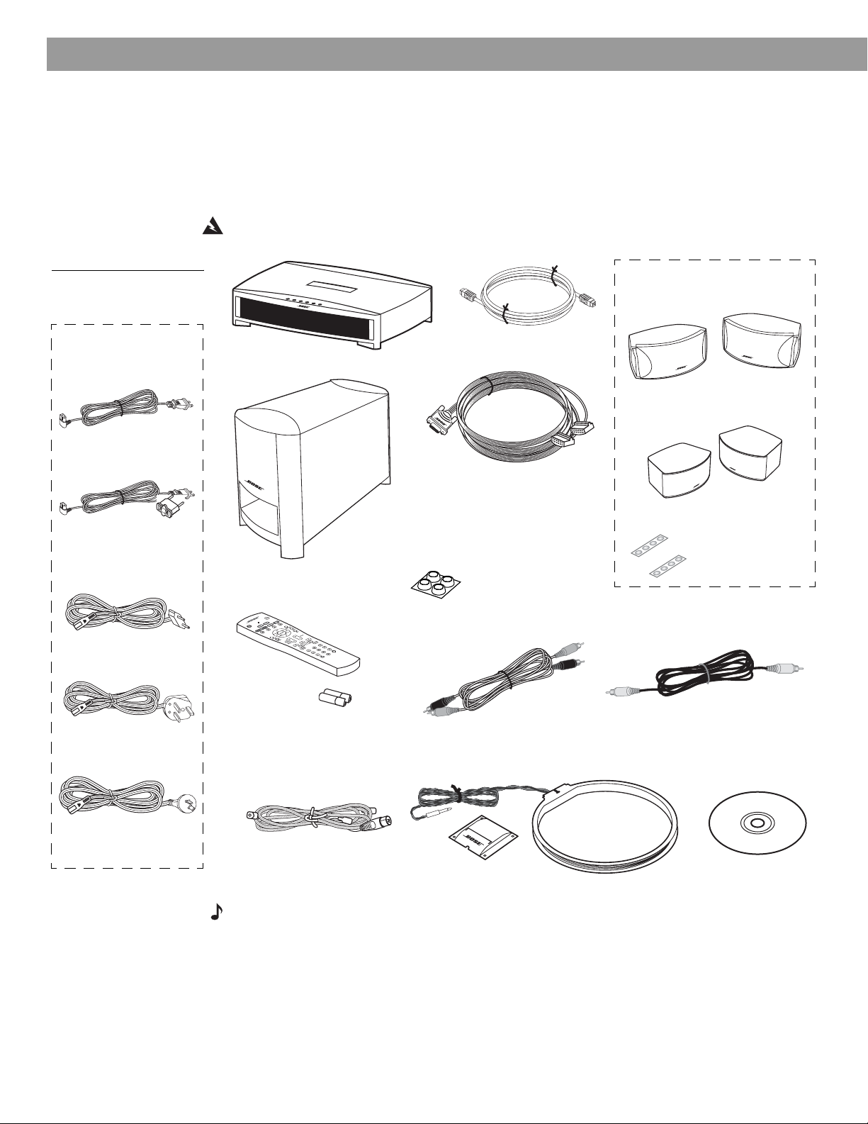
Figure 1
Contents of the shipping
carton
Your system includes
one of the following
cords:
120 VAC power cord
(US/Canada)
115/230 VAC power
cord with adapter
(US/Europe)
230 VAC power cord
(Europe)
Media center
Remote
control
Acoustimass
module
®
Acoustimass
Speaker cable
Note: If you purchased a 3•2•1
GS Series II system, the left and
right speaker cable connectors
will be marked with a “GS”.
Rubber feet for
Acoustimass
module
module
cable
Your system includes one the
following speaker types:
3•2•1 speakers
or
3•2•1 GS speakers
Rubber feet for
speakers
230 VAC power cord
(UK/Singapore)
240 VAC power cord
(Australia)
8
Batteries
FM antenna
Stereo cable
AM antenna
Antenna stand
Video cable
Setup and
demo disc
Note: Now is a good time to find the serial numbers on the bottom of the media center and
Acoustimass module. Copy these numbers onto your product registration card and in the space
provided on page 7.
Page 9
System Setup
Selecting locations for your 3•2•1 Series II system components
Use the following guidelines and Figure 2 to choose locations and positions for the components of your 3•2•1 home entertainment system.
Note: While these guidelines are offered to help provide great system performance, you may find
other placement choices that are more convenient and provide the sound you enjoy.
Placing the media center
CAUTION: Do not block any ventilation openings. For reliable operation of the product and to
protect it from overheating, put the product in a position and location that will not interfere with its
proper ventilation. For example, do not place the product on a bed, sofa, or similar surface that
may block the ventilation openings. Do not put it in a built-in system, such as a bookcase or cabinet that may keep air from flowing through its ventilation openings.
• Place the media center where nothing obstructs opening the disc tray on its front panel.
• Make sure the media center will be placed close enough to the Acoustimass
the speakers so that all the cables will reach.
• Make sure the media center will be placed close enough to additional source devices (TV,
VCR or cable box) so that all the cables will reach.
Note: Make sure that the front of the media center is unobstructed so that it may receive
IR (infrared) commands from the remote control.
®
module and
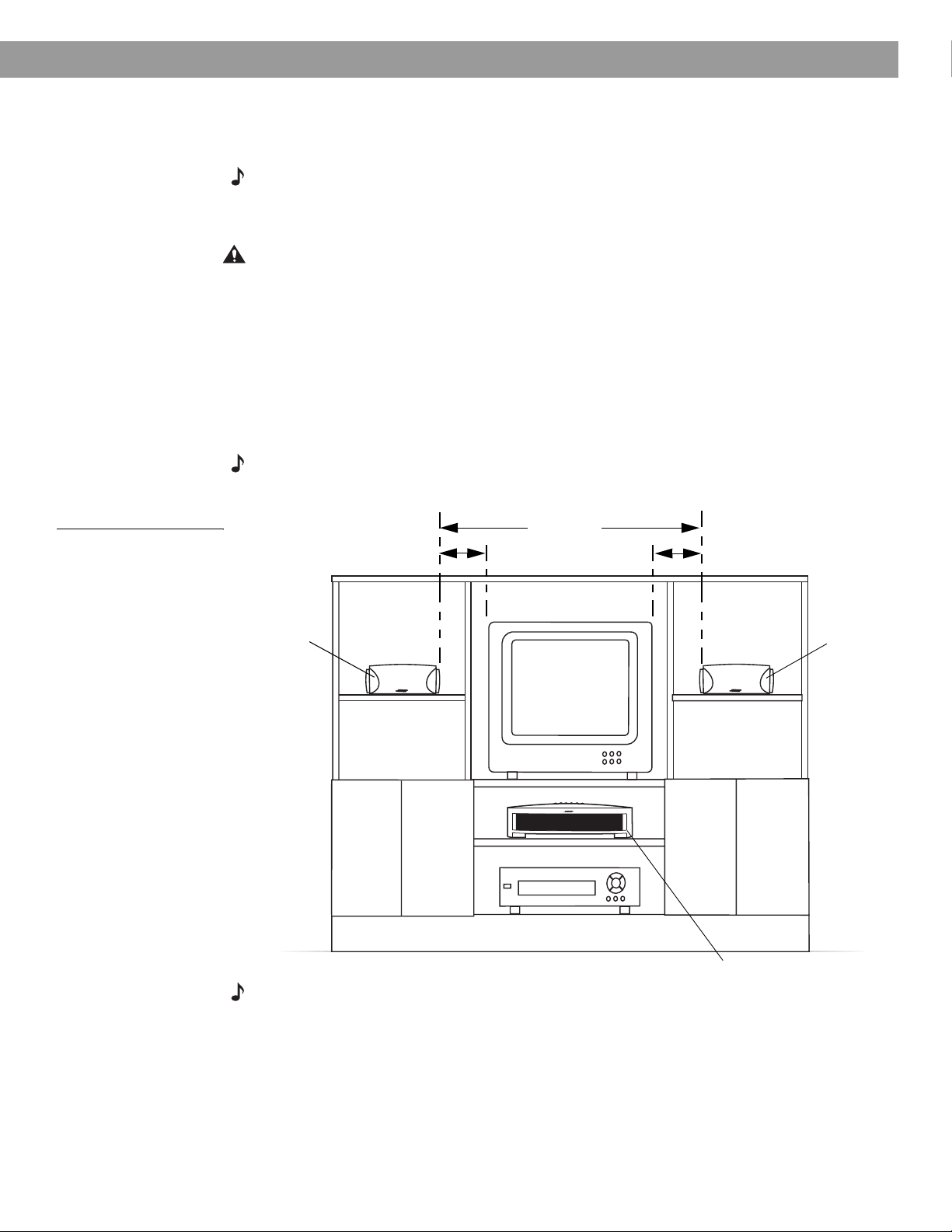
Figure 2
Sample media center and
speaker placement
Left
speaker
3 ft (1 m)
maximum
3 ft (1 m)
minimum
3 ft (1 m)
maximum
Right
speaker
Media center
Note: The speakers are magnetically shielded to prevent interference with the TV screen.
9
Page 10
System Setup
Placing the speakers
Choosing a good location for the speakers will allow you to experience the audio surround
effects that your 3•2•1 home entertainment system is designed to deliver.
• Place the two speakers either on top of the TV or at equal distance from the left and right of
the TV screen (Figure 2). Keep both speakers at approximately the same height.
• Place each speaker within 3 feet (1 meter) of the edge of the TV screen. Placing the
speakers more than 3 feet away from the TV can cause the sound to become separated
from the picture.
• If you are using a bookshelf or a home entertainment unit, place each speaker at the
front edge of its shelf
change the overall quality of sound and alter the movie sound effects.
• Place the speakers at least 3 feet (1 meter) apart from each other to optimize the
surround sound experience.
CAUTION: Choose a stable and level surface for both speakers. Vibration can cause the speakers to move, particularly on smooth surfaces like marble, glass, or highly polished wood. If you
are placing the speakers on a flat surface, be sure to attach the smaller of the two sets of supplied rubber feet to the bottom surface. You may obtain additional rubber feet (part number
178321) from Bose
product carton.
Note: The speakers can be mounted on Bose brackets, table stands, or floor stands. For ordering information, refer to “Accessories” on page 53. Additional or longer cables may also be
ordered.
.
Positioning the speakers too far back in an enclosed space can
®
Customer Service. To contact Bose, refer to the list of offices included in the
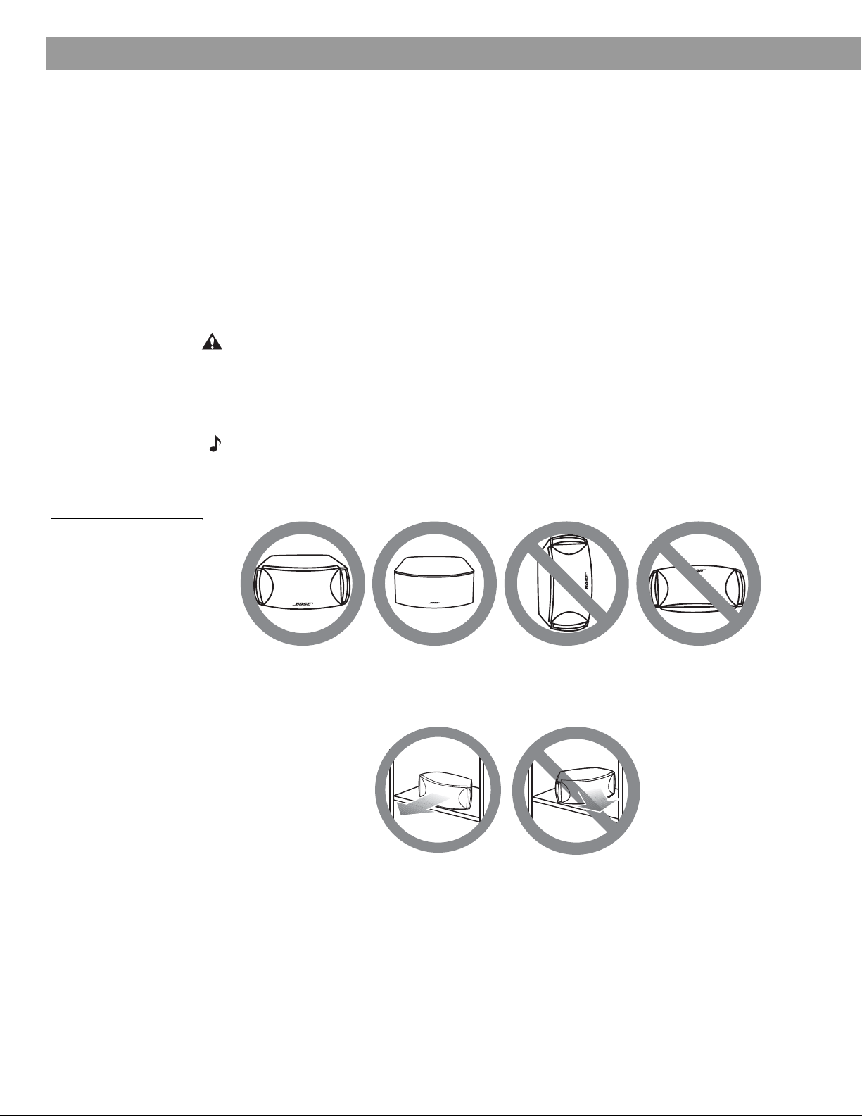
Figure 3
Recommended speaker
placement
• Place the speakers only on their bottom surfaces, with the Bose logo right-side up.
• Aim the speakers straight ahead toward the listening area. Do not place the speakers at an
angle. Angling one or both speakers into or away from the listening area signifi-
cantly alters system performance.
10
Page 11
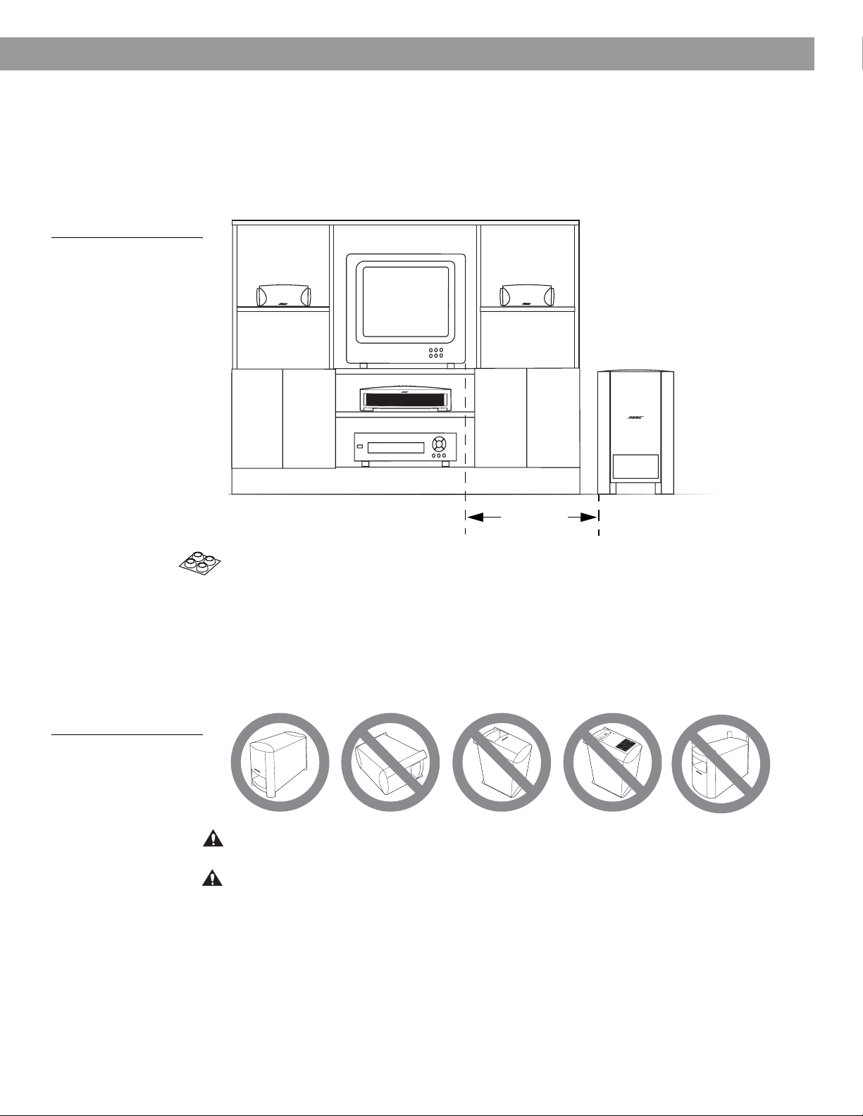
Figure 4
Recommended
Acoustimass module
placement
System Setup
Placing the Acoustimass® module
• Place the Acoustimass® module within reach of the cable from the music center and an AC
(mains) power outlet.
• Place the module at the same end of the room as the TV and the speakers (Figure 4).
• Keep the module at least 3 feet (1 meter) away from the TV to prevent the module from
interfering with the TV screen.
Figure 5
Recommended orientation
of the module
3 ft (1 m)
minimum
• Attach the medium-sized rubber feet to the bottom of each foot on the module. The rubber
feet provide increased stability and protection from scratches.
• Choose a convenient location such as under a table, behind a sofa or chair, or behind
drapes, but do not block the port opening.
• Aim the port of the module into the room or along the wall. This prevents a blocked port or
over-powering bass.
• Stand the Acoustimass module on its feet. Do not lay it on its side or stand it on either end
(Figure 5).
A
C
I
N
P
U
T
M
U
S
I
C
C
E
N
T
E
R
CAUTION: Do not block the openings on the back of the module, which provide ventilation for
the built-in circuitry.
CAUTION: The Acoustimass module generates a magnetic field. Although this is not an immediate risk to your video tapes, audio tapes, and other magnetic media, you should not store any of
these items directly on or near the module.
11
Page 12
System Setup
Making system connections
CAUTION: Do not plug the Acoustimass® module into an AC power (mains) outlet until all the
components are connected.
Note: If additional audio cables or longer cables are needed to make these connections, contact
Bose Customer Service. Refer to the list of offices included in the product carton.
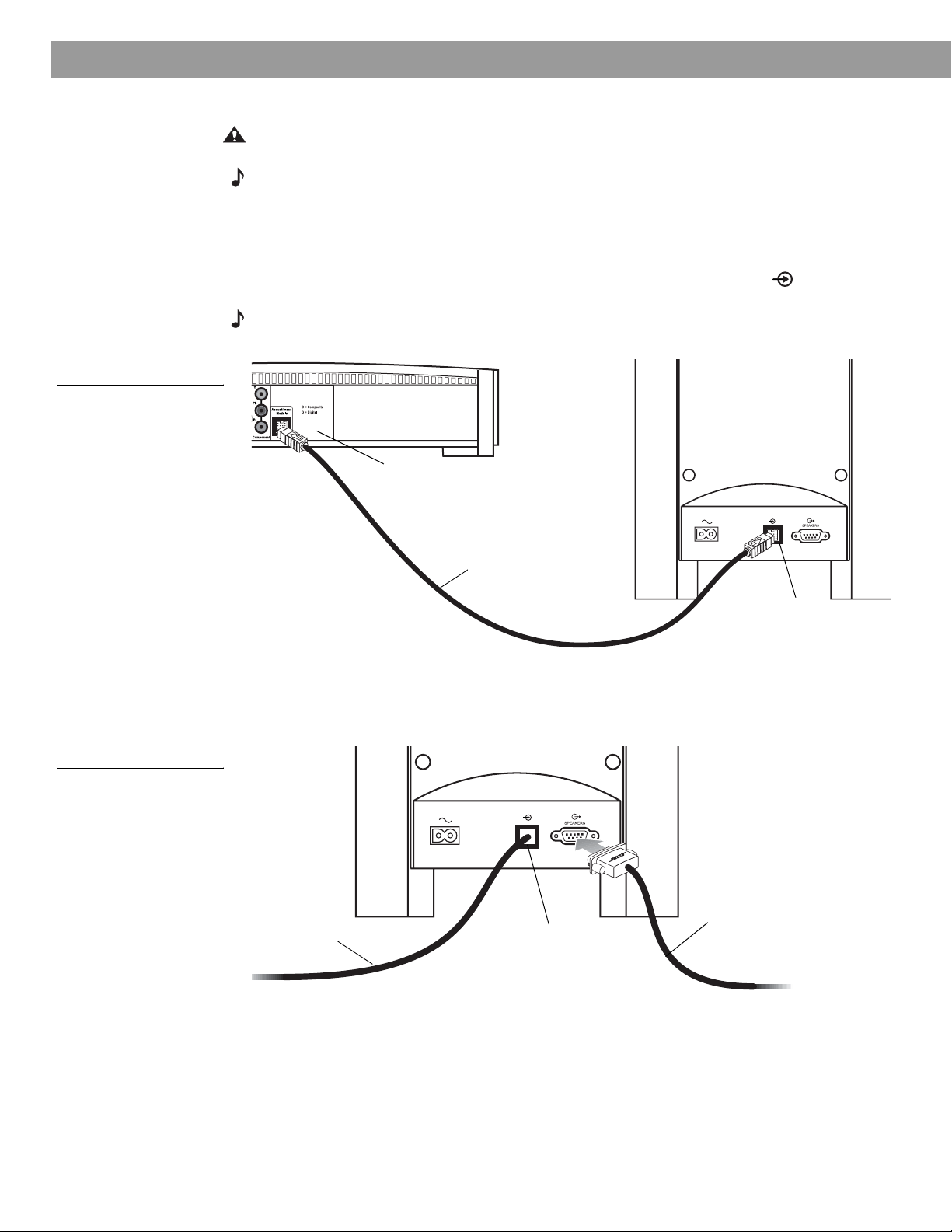
Connecting the Acoustimass module to the media center
Plug one end of the Acoustimass module cable into the
of the media center (Figure 6). Plug the other end of the cable into the input ( ) jack on the
rear of the Acoustimass module.
Note:
The jacks for the Acoustimass module cable are keyed so that the cable connectors only plug
in one way. Make sure that the arrow on the connector body faces up when plugging in the cable.
Figure 6
Acoustimass module-tomedia center connection
Media center
rear panel
Acoustimass Module
jack on the rear
Figure 7
Speaker cable-toAcoustimass module
connection
Acoustimass
module cable
Acoustimass
module input
jack
Connecting the speakers to the Acoustimass module
1. Insert the single-plug end of the speaker cable into the SPEAKERS jack on the rear
panel of the Acoustimass module (Figure 7). Tighten both screws on the plug.
Speaker
Acoustimass
module cable
Acoustimass
module input
jack
cable
12
Page 13
System Setup
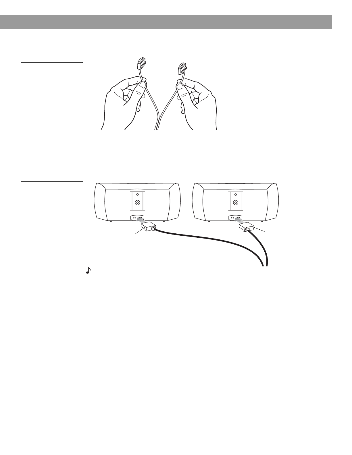
2. At the other end of the speaker cable, separate the left and right speaker cords as much
as necessary to reach each speaker (Figure 8).
Figure 8
Separating left and right
speaker cords
Figure 9
Left and right speaker
connections
Note: If you purchased a 3•2•1
GS Series II system, the left and
right speaker cable connectors
will be marked with a “GS”.
3. Plug the LEFT speaker cable into the rear jack of the left speaker (Figure 9). Plug the
RIGHT speaker cable into the rear jack on the right speaker.
T
RIGHT
speaker
cable
H
RI G
T
F
LE
LEFT
speaker
cable
Note: Make sure cable connectors are fully inserted and seated firmly in the speaker jacks.
13
Page 14
System Setup
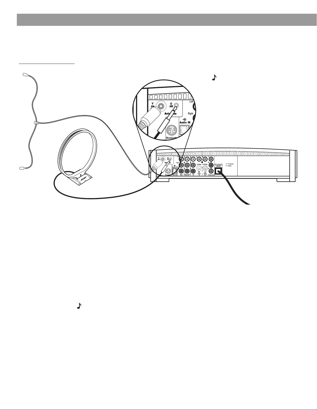
Figure 10
Antenna connections
FM dipole
antenna
Connecting the supplied antennas
The rear panel of the media center provides jacks for the AM and FM antennas included with
your system (Figure 10). Unwind the wires for each antenna to provide the best reception.
Note: An outdoor antenna may be
used in place of the supplied indoor
antennas. To add an outdoor
antenna, consult a qualified installer.
Follow all safety instructions supplied with the antenna.
Media center
AM loop antenna
FM antenna
Plug the FM antenna into the FM jack on the media center rear panel. Spread out the antenna
arms and move them around to establish optimum FM reception. Extend the antenna as far
from the media center and other equipment as possible.
AM antenna
Plug the AM loop antenna into the AM jack on the media center rear panel. Place the antenna
loop at least 20 inches (50 centimeters) away from the media center and at least 4 feet (1.2
meters) away from the Acoustimass
mum AM reception. Follow the instructions enclosed with the AM loop antenna to stand it on
the supplied base, or mount it to a wall.
Connecting cable FM radio
Some cable TV providers make FM radio signals available through the cable service to your
home. This connection is made to the external FM jack on the back panel of the media center. To connect to this service, contact your cable TV provider for assistance.
Note: Make sure that the cable radio installation includes a TV/FM splitter so that only the
FM radio band, not the cable TV band, is received by the media center. If necessary, contact your
cable company.
®
module. Experiment with positioning the loop for opti-
14
Page 15
Connecting your TV to the media center
Note: If you will be using the 3•2•1 system with both a TV and a VCR, skip this section and go
to “Connecting your TV and VCR to the media center” on page 16.
Making audio connections
Note: If your TV does not have audio output jacks, see “If your TV does not have audio output
jacks” on page 17. Otherwise, continue.
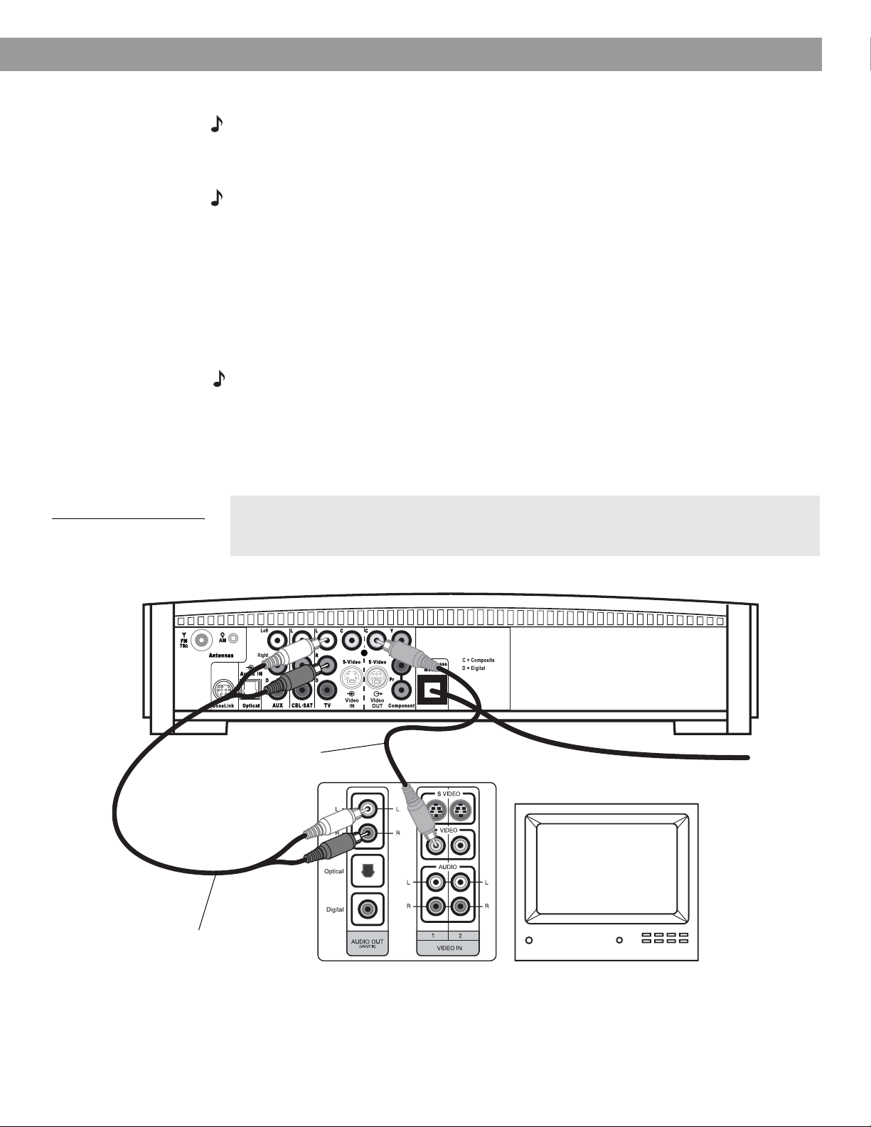
1. Connect one end of the supplied stereo cable to the TV Audio IN jacks on the rear panel
of the media center (Figure 11). Insert the white RCA plug into the TV white L jack. Insert
the red RCA plug into the TV red R jack.
2. Connect the other end of the stereo cable to the audio output jacks on your TV. Insert the
white RCA plug into the white AUDIO OUT L jack. Insert the red RCA plug into the red
AUDIO OUT R jack.
Making composite video connections
Note: Some older TVs with standard TV cable connectors do not have a composite video or an
S-video input. Such TVs are not compatible with any DVD players and require use of an RF modulator for this connection. RF modulators are available at your local electronics store.
1. Insert one end of the supplied video cable (yellow) to the Video OUT C (composite) jack
on the back of the media center (Figure 11).
2. Insert the other end of the video cable into one of the video input jacks on your TV.
System Setup
Figure 11
TV (composite video)-tomedia center connections
Remember the name of the TV video input you plugged the video cable into (for
example: Video 1, Input 1, or Aux). Later, you will need to select the corresponding
video input on your TV in order to view the 3•2•1 system video output.
Media center rear panel
Video cable
(yellow connectors)
TV connector panel
TV
Stereo cable
(red and white connectors)
*
*Could be labelled “FIXED”, “MONITOR”, or “HiFi”.
15
Page 16
System Setup
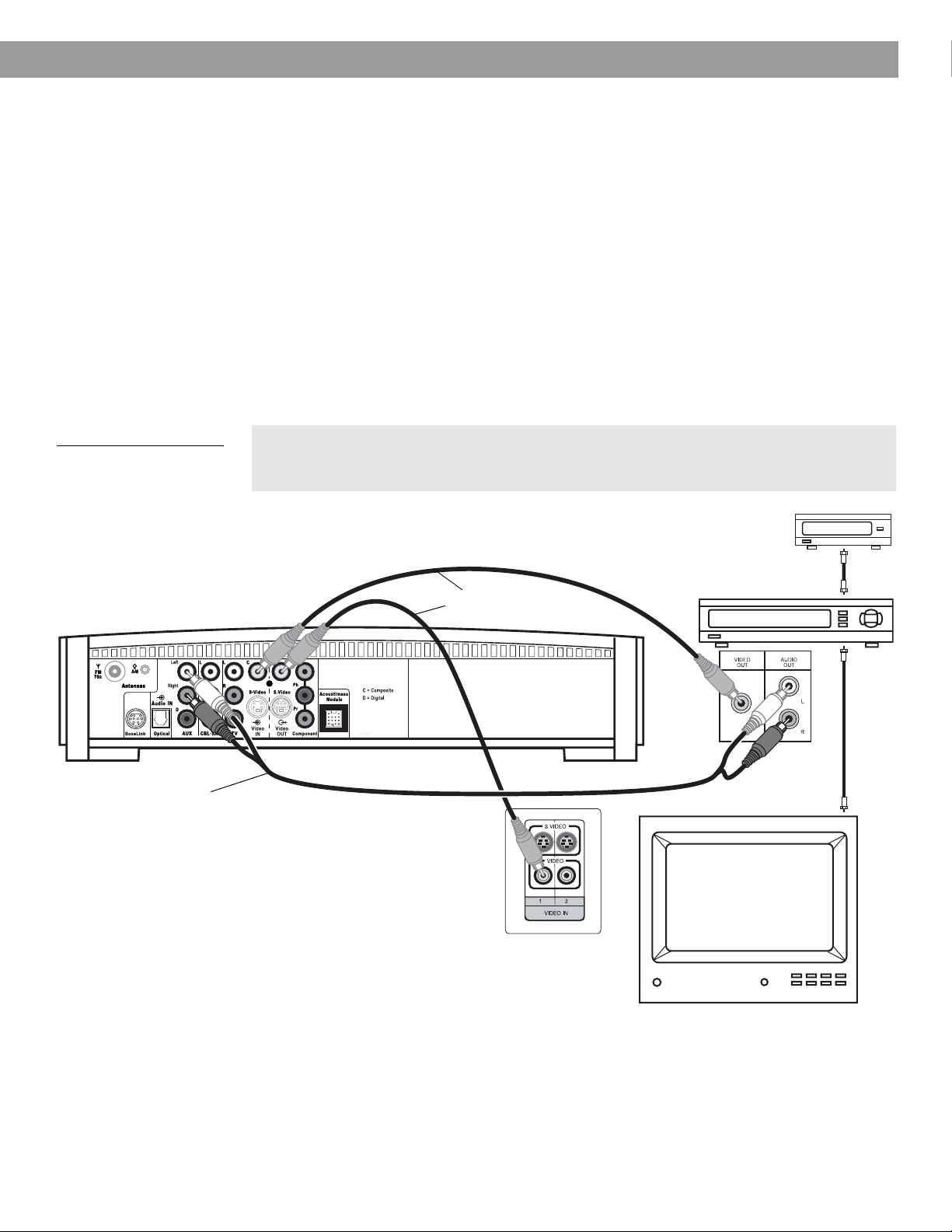
Connecting your TV and VCR to the media center
Note: There are two options for connecting your TV and VCR to the media center. Before you
proceed, you must determine if your TV has audio output jacks. Consult your TV owner’s guide if
you need assistance.
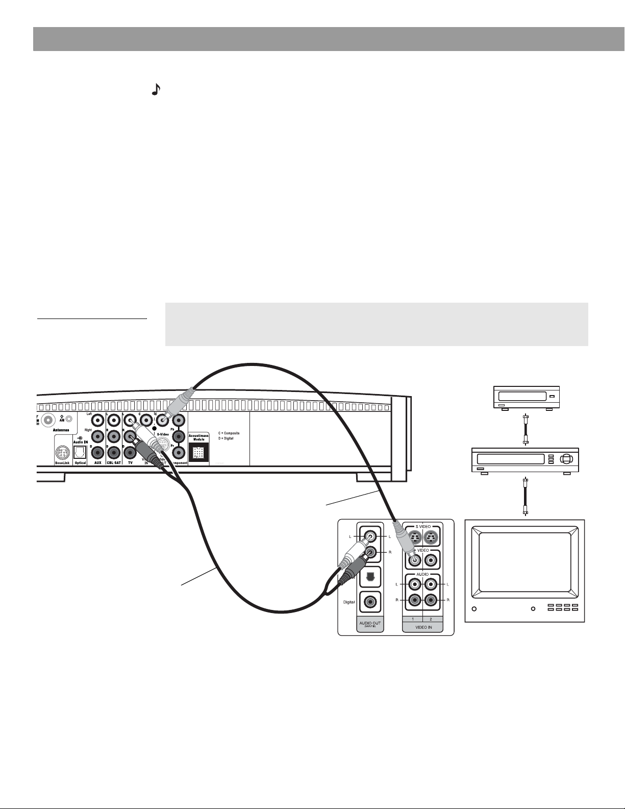
If your TV has audio output jacks
If your TV has audio output jacks, you can directly route the TV audio to the 3•2•1 home
entertainment system (Figure 12).
1. Connect one end of the supplied stereo cable to the TV Audio IN jacks on the rear panel
of the media center. Insert the white RCA plug into the TV white L jack. Insert the red
RCA plug into the TV red R jack.
2. Connect the other end of the stereo cable to the audio output jacks on your TV. Insert the
white RCA plug into the white AUDIO OUT L jack. Insert the red RCA plug into the red
AUDIO OUT R jack.
3. Insert one end of the supplied video cable (yellow) to the Video OUT C (composite) jack
on the back of the media center. Insert the other end of the video cable into one of the
video input jacks on your TV.
Figure 12
TV and VCR connections
with media center
Stereo cable
(red and white connectors)
Remember the name of the TV video input you plugged the video cable into (for
example: Video 1, Input 1, or Aux). Later, you will need to select the corresponding
video input on your TV in order to view the 3•2•1 system video output.
Cable/satellite box
(if applicable)
Existing
Video cable
(yellow connectors)
TV connector
panel
cable
Existing
cable
VCR
TV
16
*
*Could be labelled “FIXED”, “MONITOR”, or “HiFi”.
Page 17
System Setup
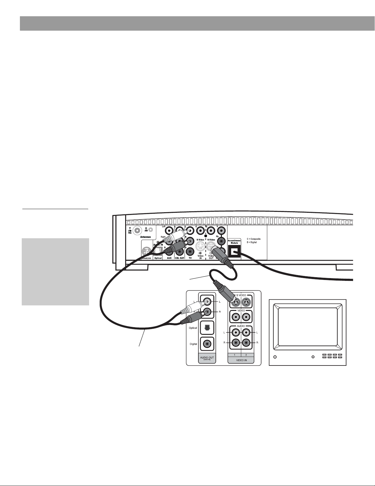
If your TV does not have audio output jacks
If your TV does not have audio output jacks, you will need to feed audio to the 3•2•1 home
entertainment system through a secondary source, such as a VCR. To do this, you will need
one additional video cable, which can be purchased at your local electronics store.
1. Connect one end of the supplied stereo cable to the AUX Audio IN jacks on the rear
panel of the media center (Figure 13). Insert the white RCA plug into the AUX white L
jack. Insert the red RCA plug into the AUX red R jack.
2. Connect the other end of the stereo cable to the AUDIO OUT jacks on your VCR. Insert
the white RCA plug into the white AUDIO OUT L jack. Insert the red RCA plug into the
red AUDIO OUT R jack.
3. Insert one end of the supplied video cable (yellow) into the VIDEO OUT jack on the
back of your VCR. Insert the other end of the supplied video cable into the Video IN C
(composite) jack on the back of the media center.
4. Insert one end of the second video cable (yellow) into the Video OUT C (composite) jack
on the back of the media center. Insert the other end of the second video cable into one
of the video input jacks on your TV.
Figure 13
System setup when TV has
no audio output jacks
Media center rear panel
Stereo cable
(red and white connectors)
Remember the name of the TV video input you plugged the video cable into (for
example: Video 1, Input 1, or Aux). Later, you will need to select the corresponding
video input on your TV in order to view the 3•2•1 system video output.
IMPORTANT
If you connected your TV and VCR this way, you
will need to turn on your VCR and select the
AUX source on the 3•2•1 remote to hear sound
from TV programs.
Video cables
(yellow connector)
TV connection panel
Cable/satellite box
VCR
TV
Existing
cable
VCR
connection
panel
Existing
cable
17
Page 18
System Setup
VCR considerations
• Some combination TV/VCR units may not work with 3•2•1 Series II home entertainment
systems. Please refer to your TV/VCR owner’s manual for information.
• A stereo VCR is required for optimal sound performance. If your VCR has only one audio
output and is not labeled Stereo or Hi-fi, you have a mono VCR. You will need a
Y-adapter cable (available at electronics stores) to connect audio to the media center. For
this setup, you will need to select “Mono decoding” (see “TV, CBL-SAT, and AUX settings
menu” on page 43) so your 3•2•1 system will simulate surround sound effects from a mono
source. Otherwise, you will hear mono sound from both speakers.
Advanced setup options
Making S-video connections (higher quality video)
An S-video input jack, provided on many TVs, delivers a higher quality TV picture than the
composite video output connection shown in Figure 11. For this connection you will need an
S-video cable which can be purchased from your Bose dealer or a local electronics retailer.
• Insert one end of the S-video cable into the S-Video OUT jack on the media
center (Figure 14).
• Insert the other end of the S-video cable into the S-VIDEO IN jack on your TV.
Figure 14
TV (S-video)-to-media
center connections
IMPORTANT
If you use S-video to
connect your TV to the
media center, you
must also use S-video
to connect all other
devices (such as a
cable box and VCR) to
the media center.
Media center rear panel
S-video cable
TV connector panel
TV
Stereo cable
(red and white connectors)
18
Page 19
System Setup
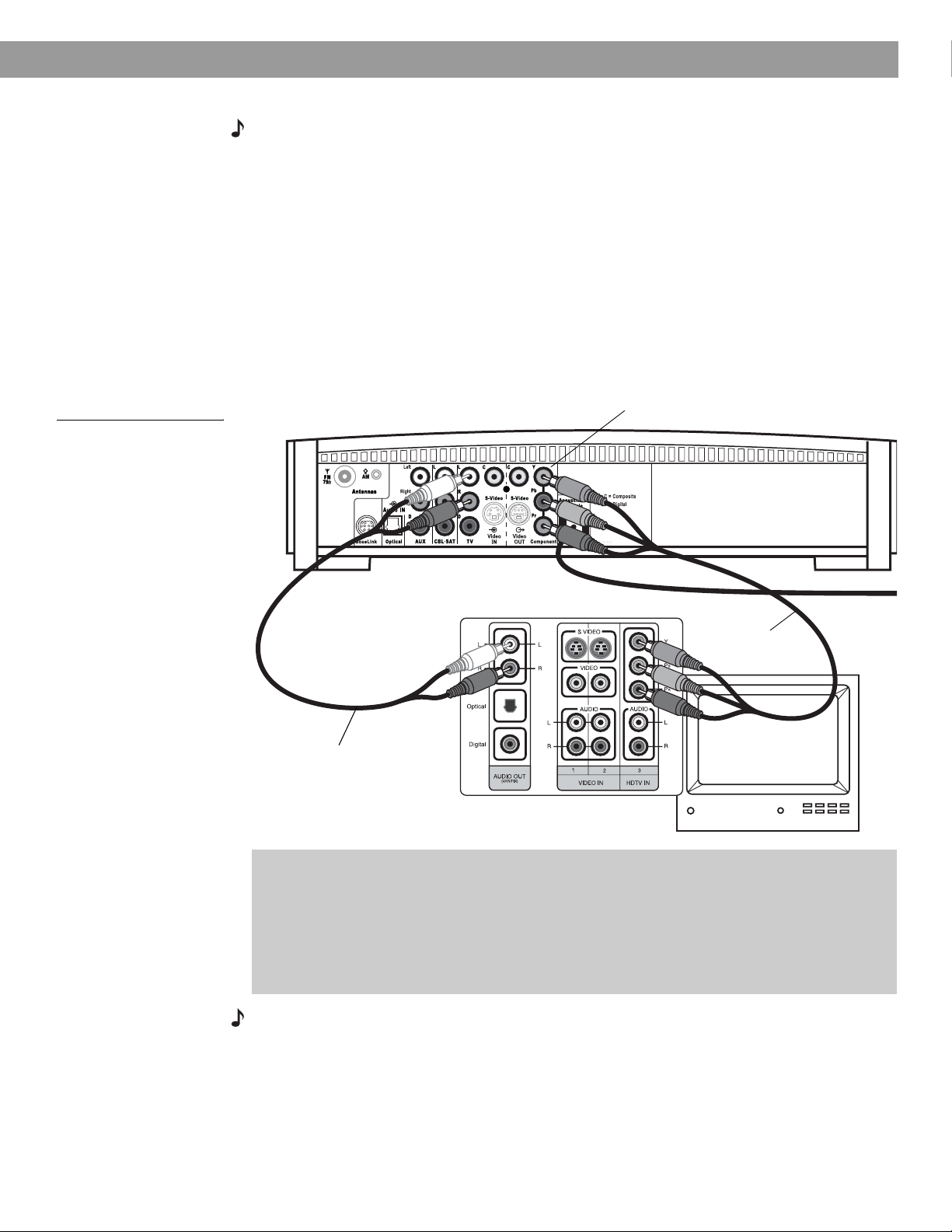
Making component video connections (highest quality video)
Note: Component video connections are required in order to use the progressive scan feature of
your 3•2•1 system. Your TV must also support this feature. To turn on the progressive scan feature, see “Video options” on page 47.
For the highest quality video from DVDs, you may want to use a component video connection
between the media center and the TV. To do so, your TV must provide component video jacks
(typically labelled Y, Pb, and Pr). Refer to your TV owner’s guide for more information.
To make component video connections you will need three video grade cables that are long
enough to reach from the rear of the media center to your TV (Figure 15). If the cables are not
supplied with your TV, you can purchase them separately.
1. On the media center rear panel, plug one video cable into the Component Y, Pb, and Pr
video output jacks (Figure 15).
2. Plug the other end of each video cable into the corresponding (color or letter code) component video jack on the back of your TV.
Figure 15
TV (component video)-tomedia center connections
Media center rear panel
Stereo cable
(red and white connectors)
Color-coded component video
jacks (Y, Pb, and Pr)
TV connector panel
Component
video cable
IMPORTANT FOR COMPONENT VIDEO USERS
Input signals received by the C (Composite) or S-Video IN jacks are not passed through to
the Component video OUT jacks. If you connect an external video device to the C or
S-Video IN jack, you must also connect the C or S-Video OUT jack on the media center to
the respective video input jack on your TV. To view the external video input on your TV, you
will need to select the TV video input used for that device. To view the onscreen menus of
the 3•2•1 system, you will need to switch back to the TV’s component video input.
Note: For more information, or to purchase the video cables, contact your local electronics store
or authorized Bose dealer.
19
Page 20
System Setup
Figure 16
Media center digital audio
input jacks
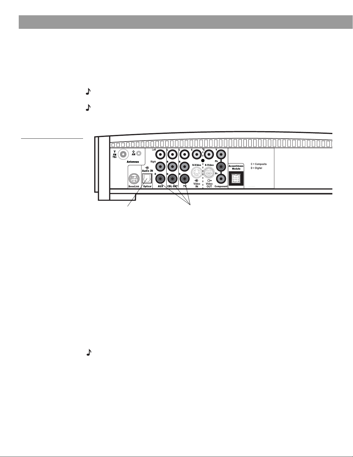
Connecting digital audio devices
Some audio devices may feature a digital audio output for optimum sound performance. Use
an optical digital cable or a coaxial digital cable, as appropriate, to connect this output to the
digital input on the media center. You can purchase the required cables at a local electronics
store.
On the media center rear panel, an optical digital cable connects to the OPTICAL jack. A
coaxial cable connects to the audio input jacks labeled D.
Note: The digital audio inputs of the 3•2•1 system are not able to decode a DTS bitstream from
an external audio device. Only a DTS bitstream from the internal DVD player can be decoded.
Note: Before you can benefit from the optical connection, you will need to assign the optical
connector to the audio source in the system settings menu. See “Media center options” on
page 48.
Optical digital
audio input
Coaxial digital
audio inputs
Connecting your cable/satellite box, TV, and VCR to the media center
The 3•2•1 home entertainment system provides flexibility for you to add up to three external
audio devices, including your TV, directly to the media center.
Figure 17 shows you an advanced setup using a TV, VCR and cable/satellite box. In this
setup, please notice the following:
• S-video connections are used to deliver the cable/satellite signal to the media center.
Therefore, the media center output video is sent to the TV also through an S-video
connection.
• Analog and digital coax audio connections are shown for the cable/satellite box. As an
option, you may use an optical digital connection. However, before you can benefit from the
optical connection, you will need to assign the optical connector to the cable/satellite box
audio source in the system settings menu. See “Media center options” on page 48.
• When connecting an audio device to the media center jacks, remember to match the red
jack to the right channel (R) and the white (or black) jack to the left channel (L).
• For further details on making the video connections between your VCR and TV, refer to the
manuals for these video devices.
Note: The recommendations contained in this owner’s guide are basic suggestions for connecting external devices to the 3•2•1 Series II system. Instructions and terminology pertinent to these
external devices may vary, depending on the manufacturer. Consult the owner’s guide that came
with the device for clarification on setup and usage before making any connections.
20
Page 21
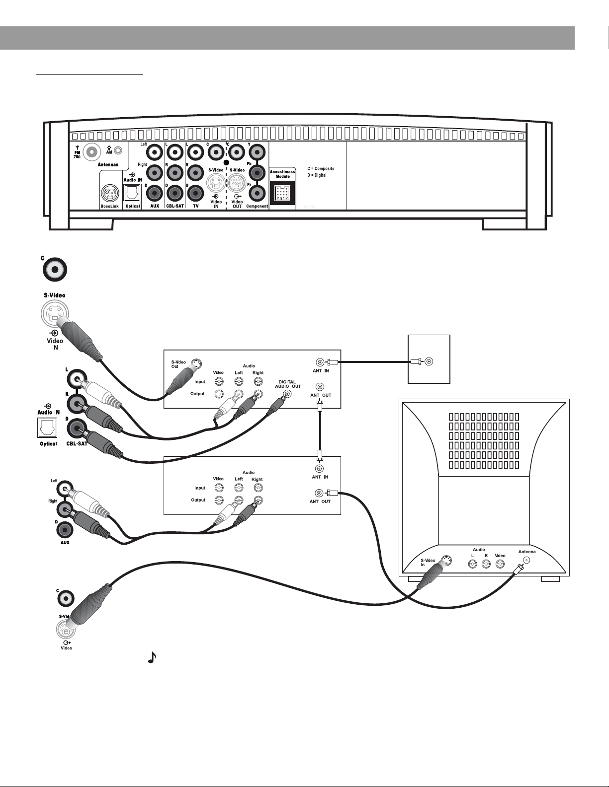
Figure 17
Advanced setup: TV, VCR
and cable/satellite box
System Setup
Media center
Cable/satellite
(CBL-SAT)
service
CBL-SAT
S-video
output
CBL-SAT analog
audio
VCR analog audio
Cable/satellite
CBL-SAT
digital audio
VCR
Media center’s
S-video output
to TV
CBL-SAT
signal to
VCR
TV
CBL-SAT
signal to
TV
Note: For more information on advanced connections, refer to the DVD setup disc that came
with your 3•2•1 Series II home entertainment system.
21
Page 22

System Setup
Figure 18
Game console connections
Game console
connection panel
Connecting a game console
Connect the audio output of a game console to the AUX Left and Right input jacks. Connect the video output of the game console to the C (composite) Video IN jack.
Media center
TV connection panel
IMPORTANT
If you connected your game console this way, you will
need to select the AUX source on the 3•2•1 remote in
order to hear sound from the game console.
22
Page 23

Installing the remote control batteries
1. On the back of the remote, slide open the battery compartment (Figure 19).
2. Insert the two supplied AA (IEC-R6) 1.5V batteries, or their equivalent, as shown. Match
the plus (+) and minus (–) marked on the batteries with the plus (+) and minus (–) inside
the battery compartment.
3. Slide the battery compartment cover back into place.
System Setup
Figure 19
Installing the batteries
Note: R
compartment
eplace the batteries when the remote control stops operating or its range seems reduced.
(2) AA batteries (IEC R6)
Battery
door
+
+
23
Page 24

System Setup
Connecting the power cord
Figure 20
Connecting to power
CAUTION: For dual voltage models only, be sure to set the dual voltage switch on the back of
the Acoustimass
®
module to the appropriate voltage for your area (115V or 230V) before connecting to power. If you are not sure about the proper voltage for your area, consult your local
electrical authorities.
1. Insert the small connector end of the power cord into the AC INPUT connector on the
Acoustimass module (Figure 20).
2. Insert the large end of the cord into an AC power (mains) outlet.
Note: On 220-240V models only, turn the Acoustimass module POWER switch to on (l).
AC power
switch
Note: Provided only on 220-240V
rated systems
115/230V
selection
switch
115V
Note: Provided only on 115/230V
dual voltage rated systems
AC input
jack
24
Page 25

Checking your system setup
1. Check the following before you continue:
• All cables are connected for the setup you chose.
• The batteries were installed in the remote control.
• The power cord was installed and plugged into a live AC receptacle.
2. Turn on your TV. Use the remote control that came with your TV.
3. Select the right video input on your TV to view the 3•2•1 system video output.
• Refer to the name of the TV video input you used during setup.
• Use the remote for your TV to select the video input for your 3•2•1 system. The video
input button might be labelled “TV Input”, “TV/VCR”, or “AV”. Refer to your TV’s
owner’s guide for help.
4. Turn off the speakers on your TV.
• Refer to your TV’s owner’s guide for help.
• If your TV does not have an option to turn off the internal speakers, you may need to
adjust both the 3•2•1 system volume and your TV volume until you find a level that
produces the desired sound.
• In some TVs, when the internal speakers are turned off, you may need to raise the TV’s
volume level by 75% to 100% in order to hear audio from the 3•2•1 home entertainment system. See your TV owner’s guide for help.
System Setup
5. Turn on your 3•2•1 system.
• Point the 3•2•1 remote control at the media center and press On-Off.
6. Play the 3•2•1 setup DVD.
•Press Eject on the media center control panel.
• Insert the DVD setup disc into the disc tray.
•Press Eject again to close the tray. The DVD will automatically begin to play. If it does
not, press the play button ( ).
Note: Be sure to play the Setup DVD, included in the carton with your system, as soon as all the
connections are completed. This will help you verify the connections you have made and confirm
proper sound performance.
25
Page 26

System Controls and Indicators
Remote control
On
Remote
status
LED
Turns the system on or off.
Off
Status LED:
• Remains off (unlit) during normal operation.
• Remains on during setup mode. Turns off briefly with each key press.
• Blinks rapidly eight times if the wrong key is pressed during setup or if an
unavailable device code is entered.
• After ten seconds of no key presses, blinks rapidly eight times and the remote
exits the setup mode.
Silences or restores the sound from the current source.
Selects the built-in CD/DVD player and turns the system on.
• Selects the built-in tuner and turns the system on to the previously selected
FM/AM station.
• Switches between FM and AM when the tuner is selected.
TV: Turns your system on and selects the TV input as the sound source.
Input: Changes the external input to your TV. For example, your TV
might have two external inputs where one is connected to your cable
box and the other to your VCR. Pressing this button alternates between
the cable box and the VCR.*
On/Off: Turns your TV on and off.*
CBL-SAT: Turns your system on and selects the CBL-SAT input as the sound
source.
On/Off: Turns your cable/satellite box on or off.*
AUX: Turns your system on and selects the AUX input as the sound source.
AUXAUX
On/Off: Turns a VCR or PVR that is connected to the AUX jack on or off.*
* Requires special remote settings. See “Setting up your remote to control other audio/video devices”
on page 35.
26
Page 27

Remote control – cont.
System Controls and Indicators
Puts the Settings menu for the current source on your TV screen or media
center display.
Puts the System menu on your TV screen.
• Puts the DVD menu of the currently loaded DVD disc on your TV screen.
• Puts the main menu of a cable/satellite box, VCR, or PVR on your TV
screen (if supported).*
Puts the TV program guide (if supported) on your TV screen.
Dismisses the Settings menu, System menu, or TV program guide (if supported) from your TV screen or media center display.
• Tunes the FM or AM radio to the next higher or lower frequency.
• Selects the next item, up or down, in menus.
Confirms a menu selection or introduces the next level of menu options.
Moves up, down, left, or right in onscreen menus and media center
displays.
*Requires special remote settings. See “Setting up your remote to control other audio/video devices” on
page 35.
27
Page 28
System Controls and Indicators
Remote control – cont.
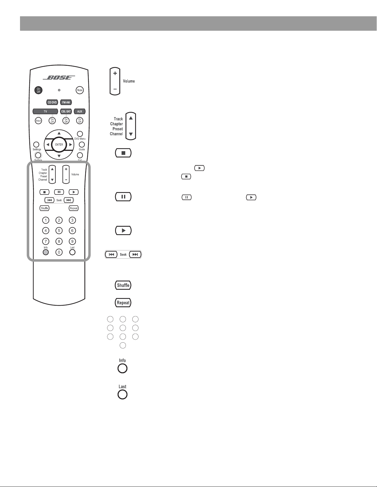
• Raises or lowers the volume of the current source.
•Pressing + restores muted sound from the current source.
•Pressing – lowers the volume of the current source, but does not restore
Skips to the next or previous CD track, DVD chapter, radio station preset,
or TV channel (if the remote is set up to control your TV).
• Stops the disc player.
•
• Pauses a currently playing disc.
• Pressing again (or pressing ) resumes play of a paused disc.
• After 20 minutes of no user interaction, the disc player stops and returns
muted sound.
For DVDs only
, the disc stops and the system saves the DVD play position. Pressing continues the DVD from the saved play position.
Pressing twice for a disc in play returns to the beginning of the disc.
to the beginning of the disc to wait for the next command.
1203
456
789
Starts the disc player.
• Skips backward or forward through CD tracks.
• Skips backward or forward through DVD chapters.
• Seeks backward or forward to the next strongest radio station.
Plays audio CD tracks in random order. Press again to cancel this mode.
Repeats a CD, CD track, DVD chapter, or DVD title. Press again to change
the repeat mode.
• Provides a means for selecting a CD track, DVD chapter, radio station
preset, or TV channel.
• Allows you to change numerical values for some menu options.
• Displays or dismisses a cable/satellite information window, if supported.
• If playing an MP3 CD, displays or dismisses artist and title information
on the media center display panel.
Skips to the previous TV channel (if supported by your TV).
28
Page 29

The media center
System Controls and Indicators
The media center has a control panel on the top, a display area to show the current status of
the system, and a disc tray that opens on the front of the console.
Control panel
The media center has six buttons located on the top control panel. Their functions are also
available through use of the remote control.
Figure 21
Media center controls
Figure 22
Sample media center
display
On-Off Source – Volume + Enter Eject
Turns system
power on or
off.
®
Steps through
the available
source
selections.
Lowers or raises
the volume level.
•Used to navigate
through menus.
• Selects the next
available FM/AM
preset.
Opens or
closes the
disc tray.
Note: If you selected another source by pressing the Source button, you cannot control the
new source with the remote until you press the button for that new source on the remote.
Display indicators
With the system turned on, the music center display lights up to show the state of the
system. Not all possible choices, shown below, light up at once (Figure 22). The display
changes with each adjustment or selection you make.
Lights to indicate
DVD 0:06:11
CHAPTER 1/12
Lights to indicate
shuffle mode is
selected for the
current disc.
SHUFFLE REPEAT DISC TRACK
Lights to indicate
repeat mode is
selected for current track or disc.
Lights to indicate
“Repeat Disc” or
“Shuffle Repeat
Disc” mode is
selected.
disc is in play.
Lights briefly when a
remote control command is received.
Lights to indicate
“Repeat Track”
mode is selected.
29
Page 30

Operation
Turning your system on and off
To turn power on or off:
• Point the 3•2•1 remote at the media center and press On/Off.
OR
•Press On-Off on top of the media center.
To turn the system on to a source:
•Press CD-DVD, FM-AM, TV, CBL-SAT, or AUX on the 3•2•1 remote.
Note: Your 3•2•1 remote control can be set up to control other audio devices such as your TV,
VCR, or cable/satellite receiver. For instructions, see “Setting up your remote to control other
audio/video devices” on page 35.
Playing video DVDs
Before you play your first DVD:
• Familiarize yourself with the 3•2•1 remote control. See “Remote control” on page 26.
• Be sure you understand how to switch between the available video inputs on your TV. To
view a video DVD, you will need to select the video input on your TV that is connected to
video output of the 3•2•1 media center (see “Connecting your TV to the media center”
on page 15).
• If you are unable to select the correct video input on your TV, please consult your TV’s
owner’s guide.
• Be sure that you play the 3•2•1 system setup DVD first. This will help you verify the connections you have made and confirm proper sound performance.
1. Turn on your TV.
2. On the 3•2•1 remote, press CD/DVD to turn the 3•2•1 system on to the CD/DVD source.
3. On the media center control panel, press Eject to open the disc tray.
4. Place the DVD disc in the disc tray.
5. Press Eject again to close the tray.
The DVD should begin to play automatically. If not, press Play on the 3•2•1 remote.
Note: Not all DVDs offer the same features. For example, you can choose to display subtitles
while watching a movie only if that particular disc provides subtitle information.
30
Page 31

Figure 23
Sample display for
a DVD video
Operation
While a DVD video is playing, elapsed play time and chapter number are displayed on the
media center front panel.
DVD 0:06:11
CHAPTER 1/12
Basic DVD operations
•Press Pause to pause a movie.
OR
Eject
•Press Pause again, or press Play to resume playing a paused CD.
• Use the stop button ( ) to interrupt a movie in play.
• Press once to interrupt a playing movie. The system holds the movie at the point of
interruption. Press Play to resume play from the point of interruption.
OR
• Press twice. Play is interrupted and the system returns to the beginning of the disc.
Press Play to restart the video.
•Press Chapter to skip to the next chapter on the current DVD. Press Chapter to skip
to the previous chapter.
•Press Repeat while a chapter is playing to make it repeat.
• Press to scan backward through the current DVD. Press to scan forward.
•Press Eject on the media center to stop a disc and open the disc tray.
Note: For information on changing DVD-related source settings, see “DVD settings menu” on
page 42.
Restricting access to video DVDs
The DVD Lock menu allows you to restrict access to video DVDs which may contain inappropriate material for certain members of your family. You can get to the DVD Lock menu by
pressing the System button on the remote control. This feature allows you to set up password access for movies which have a certain rating. For instructions on using the DVD Lock
menu, see “DVD Lock options” on page 50.
31
Page 32

Operation
Playing audio CDs
Eject
Eject
1. On the 3•2•1 remote, press CD/DVD to turn the 3•2•1 system on to the CD/DVD source.
2. On the media center control panel, press Eject to open the disc tray.
3. Place the DVD disc in the disc tray.
4. Press Eject again to close the tray.
5. The audio CD should begin to play automatically. If not, press Play on the 3•2•1 remote.
Basic CD operations
•Press Pause to pause an audio CD.
OR
•Press Pause again, or press Play to resume playing a paused CD.
• Press to stop an audio CD.
•Press Tr ack to skip to the next track on the current CD. Press Tr a ck to skip to the
previous track.
• Press and hold to scan backward through the current CD. Press and hold to scan
forward.
• Press once to advance to the next song.
•Press Repeat once for REPEAT TRACK mode. Press Repeat again for REPEAT DISC
mode. Press Repeat again to turn the repeat functions off (REPEAT OFF).
•Press Shuffle once for SHUFFLE DISC mode. Press Shuffle again to turn off the shuffle
mode (SHUFFLE OFF).
Note: For information on changing CD-related source settings, see “CD settings menu” on
page 41.
32
Note: If playing an MP3 CD, the Info button displays or clears artist and title information on the
media center display panel.
Page 33

Listening to FM/AM radio
On the 3•2•1 remote, press FM-AM. If the system is off, the radio will turn on to the most
recently selected station.
Tuning to a station
You can tune to a radio station in any of the following ways:
•Press FM-AM to switch between the FM and AM bands.
•Press Tune to tune up the band. Press Tu n e to tune down the band.
•Press Seek to go to the previous station. Press Seek to go to the next available
station. Press and hold for rapid tuning. Release to stop at the next available station. To
stop anytime, briefly press Seek or Seek . To begin seeking again without holding
down the Seek button, briefly press Seek or Seek as soon as the first seek opera-
tion stops.
Operation
1203
456
789
•Press Preset to select the next stored station. Press Preset to select the previous
stored station.
OR
• Press the number of a stored station on the keypad.
Note: For information on changing FM/AM-related source settings, see “FM/AM settings menu”
on page 41.
Storing stations as presets
Using your 3•2•1 remote control you can store up to 20 AM and 20 FM station presets. This
enables you to tune to a favorite station quickly.
1. Tune to the preferred station.
2. Store the station with an assigned preset number.
• For numbers 1-9, press the single number button and hold it. For numbers 10-20, press
the first number. Immediately after, press the second number and hold it.
•OR, press Enter on the media center to store the selected station at the next available
preset number.
The newly assigned preset number appears briefly on the media center display.
Note: Assigning a preset number to a station will replace any previous assignment of that preset.
33
Page 34

Operation
Erasing a preset
1. Tune to the preset station.
2. Press and hold the 0 button on the remote until the media center display tells you that
Playing other sources
Turn on any component connected to the media center by using the remote for that component or controls on the component front panel. Use the 3•2•1 Series II or 3•2•1 GS Series II
system remote to get started:
•Pressing TV, CBL-SAT, or AUX on the 3•2•1 or 3•2•1 GS system remote turns on the
system and selects the audio for that component. Be sure a tape or disc is loaded, as
needed.
•Use the Vo lume up or down arrows on the system remote or on the media center to raise
or lower the volume of the system.
Using the sleep timer
Your system includes a sleep timer which can be set to turn your system off automatically
after 1 to 90 minutes of listening to any source. This timer can be accessed through the
Settings menu for any source. See “Changing Source Settings” on page 39.
Note: The sleep timer will not turn off the TV or other audio device.
the preset is erased.
34
Page 35

Controlling Other Audio Devices
Setting up your remote to control other audio/video devices
Your remote can be set up to control other audio devices such as a TV, VCR, PVR or
cable/satellite box by entering a device code while in the setup mode.
• If you know the device code, follow the instructions under the heading, “Direct
entry of a device code” below. Device codes are listed in the back section of this
owner’s guide and in the System menus under Remote Control options.
• If you can’t find the device code and want to search the system for it, see
“Searching for a device code” on page 36.
• If you want to verify the device code you have entered for an audio device, see
“Verifying an entered device code” on page 38.
Note: More than one code may work with your particular brand of product. If you notice a lack of
response or limited functionality after setting up the remote, try a different code.
Note: The remote status LED flashes rapidly eight times if you press an invalid key, or enter an
unavailable device code. Wait seven seconds for the error to clear and start again.
Direct entry of a device code
Device codes can be found at the back of this owner’s guide or in the System menu under
Remote Control options. If you know the device code, you can do the following:
To set up the remote to control your TV
1. Turn on both the 3•2•1 system and your TV.
2. Press and hold the TV button until the remote LED is lit (about five seconds).
3. On the remote keypad, enter the four-digit device code for your TV. The LED will turn off
temporarily as you press each key.
4. Check that the LED turns off after the code is entered. If the LED blinks, the code is
invalid. Try again.
5. Point the remote at your TV and press the TV On-Off button. If your TV does not
respond, go back to step 2 and try other codes. If you are still unsuccessful, see
“Searching for a device code” on page 36.
To set up the remote to control your cable/satellite box
1. Turn on both the 3•2•1 system and your cable/satellite box.
2. Press and hold the CBL-SAT button until the remote LED is lit (about five seconds).
3. On the remote keypad, enter the four-digit device code for your cable/satellite box. The
LED will turn off temporarily as you press each key.
4. Check that the LED turns off after the code is entered. If the LED blinks, the code is
invalid. Try again.
5. Point the remote at your cable/satellite box and press the CBL-SAT On-Off button. If
your cable/satellite box does not respond, go back to step 2 and try other codes. If you
are still unsuccessful, see “Searching for a device code” on page 36.
35
Page 36

Controlling Other Audio Devices
To set up the remote to control your VCR or PVR (such as Tivo or Replay TV)
1. Turn on both the 3•2•1 system and your VCR or PVR.
AUXAUX
AUXAUX
2. Press and hold the AUX button until the remote LED is lit (about five seconds).
3. On the remote keypad, enter the four-digit device code for your VCR/PVR. The LED will
turn off temporarily as you press each key.
4. Check that the LED turns off after the code is entered. If the LED blinks, the code is
invalid. Try again.
5. Point the remote at your VCR or PVR and press the AUX On-Off button. If your VCR or
PVR does not respond, go back to step 2 and try other codes. If you are still unsuccessful, see “Searching for a device code” on page 36.
Searching for a device code
Use this method if you do not know the device code for a device.
Note: This is a very time-consuming process. Use it as a last resort.
To set up the remote to control your TV
1. Turn on both the 3•2•1 system and your TV.
2. Press and hold TV until the remote LED is lit (about five seconds).
3. Alternately press Channel and TV On-Off until your TV turns off.
36
4. Press Enter. Check that the remote LED turns off.
5. Point the remote at your TV and press TV On-Off. If your TV does not respond, go back
to step 2 and try again.
Page 37

Controlling Other Audio Devices
To set up the remote to control your cable/satellite box
1. Turn on both the 3•2•1 system and your cable/satellite box.
2. Press and hold CBL-SAT until the remote LED is lit (about five seconds).
3. Alternately press Channel and CBL-SAT On-Off until your cable/satellite box
turns off.
4. Press Enter. Check that the remote LED turns off.
5. Point the remote at your cable/satellite box and press CBL-SAT On-Off. If your cable/
satellite box does not respond, go back to step 2 and try again.
AUXAUX
AUXAUX
AUXAUX
To set up the remote to control your VCR or PVR (for example, TiVo or Replay TV)
1. Turn on both the 3•2•1 system and your VCR/PVR.
2. Press and hold AUX until the remote LED is lit (about five seconds).
3. Alternately press Channel and AUX On-Off until your VCR/PVR turns off.
4. Press Enter. Check that the remote LED turns off.
5. Point the remote at your VCR/PVR and press AUX On-Off. If your VCR/PVR does not
respond, go back to step 2 and try again.
37
Page 38

Controlling Other Audio Devices
Verifying an entered device code
In case you need to check to see what code the remote is using for a particular audio device,
do the following:
1. Press and hold a source key (TV, CBL-SAT, or AUX) until the remote LED lights (about
five seconds)
2. Press the Info button.
3. Press 1 on the remote and count the number of times the LED blinks (zero is indicated by
a long blink). This is the first digit.
4. Press 2 on the remote and count the number of times the LED blinks (zero is indicated by
a long blink). This is the second digit.
5. Press 3 on the remote and count the number of times the LED blinks (zero is indicated by
a long blink). This is the third digit.
6. Press 4 on the remote and count the number of times the LED blinks (zero is indicated by
a long blink). This is the fourth digit.
7. Press Exit.
Changing channel selection control
If you are using your 3•2•1 home entertainment system with other audio devices, such as a
VCR and cable/satellite box, you may wish to change channels using one of these other
audio devices rather than your TV.
You can easily switch your 3•2•1 remote to change channels on another audio device:
1. Press and hold Last on the 3•2•1 remote. The remote status LED will illuminate and blink
the number of times corresponding to the device controlling channel selection.
1 blink = TV
2 blinks = CBL-SAT
3 blinks = AUX
2. After the blinking stops, press the source button (TV, CBL-SAT, or AUX) that corre-
sponds to the device you want to use for channel selection.
3. Press Exit on the 3•2•1 remote.
To confirm, press and hold Last on the 3•2•1 remote and count the number of blinks. If the
change was made, press Exit. If not, repeat steps 2 and 3.
38
Page 39

Using the settings menus
While watching a video or listening to music on your system, you can make quick adjustments that will increase your enjoyment of the program. For that purpose, each source you
use with this system has its own Settings menu with features appropriate to that source.
To view the settings menus
You can see the Settings menu for each source on your TV screen (Figure 24) and on the display panel of your media center (Figure 25).
1. Turn on your TV and select the correct TV input to view your 3•2•1 system.
2. Press a source button on your 3•2•1 remote control.
3. Press Settings to display the Settings menu for the selected source.
If the list of menu items is too long for the screen, a small down or up arrow indicates that
you need to scroll down or up to see other items.
4. Press Exit to dismiss the Settings menu.
Changing Source Settings
Figure 24
Sample Settings menu on
your TV screen
Source name
Tuner
Menu item name
Output Mode: Auto
Menu items
Setting
Selection box
Navigation help - which buttons to use
Note: Any changes made in the settings menu on your TV screen will also appear in the media
center display panel.
On the media center display panel, menu items will scroll in and out of view as you press the
up ( ) and down ( ) arrow buttons on the remote.
Figure 25
Sample Settings menu on
the media center display
>Output Mode: Auto
Sleep Timer: Off
SETTINGS
39
Page 40

Changing Source Settings
To make changes in the settings menus
Whether you use your TV screen or the media center display to change settings, the same
instructions apply.
You can use the actions above to change back to the original (default) settings, too. Do that if
you do not like the effect of a change you have made, or accidentally made a change you did
not intend. The default settings for each source are shown in the menu tables on the following
pages.
1. Turn on your TV and select the correct TV input to view your 3•2•1 system.
2. Press a source button on your 3•2•1 remote control.
3. Press Settings to display the Settings menu for the selected source.
4. Using the down ( ) and up ( ) arrow buttons, select the menu item you want to change.
5. Press the right arrow ( ) button to select the menu item setting.
6. Press the up ( ) or down ( ) arrow button to change the setting.
7. Press Enter or the left arrow ( ) button to save the setting.
8. Press Exit to dismiss the Settings menu.
The progression in Figure 26 shows output mode for the FM tuner being changed from Auto
to Stereo.
Figure 26
Changing the FM output
mode setting
Tuner
Output Mode: Auto
The down arrow
button was pressed
to select the Output
Mode menu item.
Tuner
Output Mode: Auto
The right arrow
button was
pressed to select
the setting.
Note: You can restore all default settings by choosing Restore Settings in the Systems menu,
under Media Center options. This reverts all source settings back to the factory default settings. It also changes the Audio Processing setting back to Automatic (found in the Systems
menu under Audio options).
Tuner
Output Mode: Stereo
The up or down
arrow button
was pressed to
change setting
from Auto to
Stereo.
40
Page 41

FM/AM settings menu
To see the FM/AM Settings menu, press FM-AM on the remote. Then press Settings. Press
Exit to remove the menu from the screen.
Item Name Settings Default Description
Changing Source Settings
CD settings menu
Output Mode
(FM only)
RDS Info
(FM only, and
only on some
systems)
Sleep Timer Off, 10-90
To see the CD Settings menu, press CD-DVD on the remote while playing an audio CD. Then
press Settings. Press Exit to remove the menu from the screen.
Item Name Settings Default Description
Track __ of __ Allows you to select a track on the
Sleep Timer Off, 10-90
Auto, Stereo,
Mono
Off, On Off Displays station and program infor-
minutes
minutes
Auto Allows you to listen to stereo broad-
casts in either stereo or mono output.
mation (as available from Radio Data
System).
Off Turns the system off after the set time
expires. Choose off to deactivate the
timer.
current disc.
Off Turns the system off after the set time
expires. Choose off to deactivate the
timer.
41
Page 42

Changing Source Settings
DVD settings menu
To see the DVD Settings menu, press CD-DVD on the remote while playing a DVD video disc.
Then press Settings. Press Exit to remove the menu from the screen.
Item Name Settings Default Description
Movie EQ* On, Off On Optimizes the tonal balance for movies.
Range Compression* On, Off On Adjusts volume to maintain dialogue intelligibility. Keeps
some sounds from overwhelming others.
Mono Decoding* On, Off On Engages Videostage
cess mono sound (one-channel audio) for your system.
Time _:_ _ 0:00 Displays the elapsed time of the current DVD. Also,
allows you to move to a new location in the movie by
entering a new time.
Title __ of __ Selects a DVD title from the current disc, according to
the number set. Some DVDs do not allow direct access
to titles.
Chapter _____ Selects a DVD chapter from the current DVD movie,
according to the number entered. Some DVDs do not
allow direct access to chapters.
Audio Track Dependent on
disc
Subtitle language Dependent on
disc
Camera Angle 1 of ____ Allows you to select one of the available camera angles
A-B Repeat A, B Repeats a segment of the DVD after the start and end
Allows you to choose one of the available audio tracks
on the current disc.
Allows you to choose one of the available subtitle languages (only if included on disc).
(only if included on disc).
points are defined. To begin:
1. Move backward or forward to the point in the DVD
where you want the segment to start.
2. Press Enter.
3. Move to the point where you want it to end.
4. Press Enter.
Repeats until you press the Exit or Settings button.
®
5 mono decoding circuitry to pro-
42
Sleep Timer Off, 10-90
minutes
*Available only when Audio Processing is set to User Adjustable. See “Audio options” on
page 46 for more information.
Off Turns the system off after the set time expires. Choose
off to deactivate the timer.
Page 43

TV, CBL-SAT, and AUX settings menu
The settings below affect programs on the TV, even when the source of the program is VCR,
CBL/SAT or AUX. There are no separate setting menus for these sources.
Movie EQ, Range Compression and Mono Decoding appear in the menu only if Audio
Processing is set to User Adjustable. Audio Processing can be found in the System
menu under Audio options.
Item Name Settings Default Description
Movie EQ* On, Off On Optimizes the tonal balance for
Changing Source Settings
movies.
Range
Compression*
Mono Decoding* On, Off On Engages Videostage
Dolby Digital
1+1**
Sleep Timer Off, 10-90
*Available only when Audio Processing is set to User Adjustable. See “Audio options” on
page 46 for more information.
** Available only when a Dolby Digital 1+1 signal is detected.
On, Off On Adjusts volume to maintain dialogue
intelligibility. Keeps some sounds from
overwhelming others.
®
5 mono decoding circuitry to process mono sound
(one-channel audio) for your system.
1, 2, Both 1 Plays audio content of selected
soundtrack(s).
The content of the second sound-
track may be a second language, for
example.
Off Turns the system off after the set time
minutes
expires. Choose off to deactivate the
timer.
43
Page 44

Changing System Options
Using the System menu
Changes to system options are typically made only once. If your system operates as you
want it to, there may be no need for any changes. In some cases, however, changes are
required to make the system fully compatible with the installation options you have chosen.
To view the System menu
Unlike the source settings menus, the System menu only appears on your TV screen.
1. Turn on your TV and select the correct TV input to view your 3•2•1 system.
2. Press the System button on your 3•2•1 remote control. The System menu appears with
Audio options selected, showing a list of the Audio options that can be changed.
3. Press System again, or press Exit to dismiss the System menu.
Note: Entering the System menu causes any DVD or VCD that is playing to pause.
Figure 27
Sample system menu
showing audio options
List of system options for
the selected category
Navigation help – Which remote
control buttons to use
Categories of options
Audio
Video
Media
Center
Remote
Control
Select Audio to adjust these system options:
Bass Compensation
Treble Compensation
Audio Processing
Input Levels
navigate
select
DVD
Lock
44
Page 45

Changing System Options
To change system options
Changing system options in this menu is similar to changing the settings for a source.
1. Turn on your TV and select the correct TV input to view your 3•2•1 system.
2. Press the System button on your 3•2•1 remote control.
3. Using the right ( ) and left ( ) arrow buttons, highlight one of the option categories
(Audio, Video, Media Center, Remote Control, or DVD Lock).
4. Press Enter or the down ( ) arrow to select the option category.
5. Using the down ( ) and up ( ) arrow buttons, select the system option to change.
6. Press the right arrow ( ) button to see the system option settings.
7. Press the up ( ) or down ( ) arrow button to change the setting.
8. Press Enter or the left arrow ( ) button to save the setting.
9. Press System again, or press Exit to dismiss the System menu.
45
Page 46

Changing System Options
Audio options
The audio options affect the way the system sounds in your home.
Note: Listening to an audio source while you change audio options can be helpful. Some
changes will be immediately noticeable and therefore useful in fine tuning your selections.
Figure 28
Audio system options
Audio
Select Audio to adjust these system options:
Bass Compensation
Treble Compensation
Audio Processing
Input Levels
Video
Media
Center
Remote
Control
DVD
Lock
navigate
select
System Option Settings Description
Bass Compensation 0 [default]
–14 to +14
Treble Compensation 0 [default]
–14 to +14
Audio Processing Automatic [default]
User Adjustable
Normal low-frequency reproduction.
Decreased (–) or increased (+) low-frequency reproduction.
Normal high-frequency reproduction.
Decreased (–) or increased (+) high-frequency reproduction.
Standard Bose
Processing options (Movie EQ, Range Compression, Mono
Decoding) available in Source Settings menus.
Input Levels:
TV Analog Input Level
TV Digital Input Level
Normal [default]
–6, –3, +3, +6
Standard signal level (loudness).
Decreases or increases signal level (adjustable to match the
levels of other audio devices).
CBL/SAT Analog Input Level
CBL/SAT Digital Input Level
AUX Analog Input Level
Note: You may want to adjust the input levels of external audio
devices so they match the system’s internal FM and CD levels.
AUX Digital Input Level
®
processing applied.
46
Page 47

Video options
Figure 29
Video system options
Changing System Options
The video options affect the way the picture looks on your TV.
Audio
Select Video to adjust these system options:
TV Aspect Ratio
Widescreen DVDs
Video Connector
Video Black Level
Video Format
Progressive Scan
Video
Media
Center
Remote
Control
DVD
Lock
navigate
navigate
select
select
System Option Settings Description
TV Aspect Ratio Normal [default]
Widescreen
Widescreen DVDs Modified [default]
Unmodified
Video Connector* Composite + S-Video [default]
Component
Video Black Level Normal [default]
Extended
Video Format NTSC [default]
PAL
Progressive Scan** Off [default]
On
4:3 ratio screen display.
16:9 ratio widescreen display.
Modified [default].
Unmodified.
Identifies the type of video connection made on the back panel
of the media center.
Screen black level generally appropriate for TVs.
Increases screen black level, appropriate for certain TVs.
Correct for NTSC (US standard) monitors.
Correct for PAL (European standard) monitors.
Screen image repaints in standard style.
Screen image repaints in advanced style (if available on the TV).
* A read-only item that indicates the connection detected automatically by the system.
** Appears only when Video Connector is Component.
47
Page 48

Changing System Options
Media center options
The media center options affect the general operation of the system.
Figure 30
Media Center system
options
Audio
Select Media Center to adjust these system options:
Display Brightness
Display Language
Optical Source
Tuner Spacing
Bose Link Room Code
Restore Factory Defaults
Video
Media
Center
Remote
Control
DVD
Lock
navigate
select
System Option Settings Description
Display Brightness 4 [default]
1 (darkest) to 4 (brightest)
Display Language English [default]
Media center display lights with a mid-range brightness.
Darkens or lightens the media center display.
On-screen display menus appear in the selected language.
Dansk, Deutsch, Espanol, Francais,
Italiano, Nederlands, Svenska
Optical Source None [default]
TV, CBL/SAT, AUX
Tuner Spacing US [default]
European
Bose link Room
Code*
Restore Factory
Defaults
B [default], C, D, E, F, G, H, I, J, K,
L, M, N, or O
No
Ye s
No digital signal received via optical cable.
Digital signal received via optical cable for selected source.
Channel spacing for AM/FM radio stations set to selected
region standard.
Assigns a room code to your 3•2•1 Series II system when
it is connected to a Bose
Maintains current system settings.
Reverts system settings back to factory defaults.
** Appears only when a Bose® link source is connected.
®
link source.
48
Page 49

Remote control options
The Remote Control options help you set up your remote to control other audio devices that
are connected to your system.
Figure 31
Remote Control system
options
Audio
Select Remote Control to adjust these system
options:
Video
Media
Center
Remote
Control
DVD
Lock
Changing System Options
TV Brand
TV Device Code
CBL/SAT Device
CBL/SAT Brand
CBL/SAT Device Code
AUX Device
AUX Brand
AUX Device Code
selectnavigate
System Option Settings Description
TV Brand Brand name Provides a list of TV brands for the 3•2•1 remote control to operate.
TV Device Code Code number Provides a list of available device codes for the selected TV brand.
CBL/SAT Device Cable, Satellite Identifies which of two devices is connected to the CBL-SAT input.
CBL/SAT Brand Brand name Provides a list of cable/satellite box brands for the 3•2•1 remote
control to operate.
CBL/SAT Device Code Code number Provides a list of available device codes for the selected cable/satellite
box brand.
AUX Device VCR, PVR Identifies which of two devices is connected to the AUX input.
AUX Brand Brand name Provides a list of VCR/PVR brands for the 3•2•1 remote control to
operate.
AUX Device Code Code number Provides a list of available device codes for the selected VCR/PVR
brand.
Note: To find the brand and device codes for each component that can be connected to, and
controlled by the 3•2•1 system, see “Device Codes” on page 57.
49
Page 50

Changing System Options
DVD Lock options
The DVD Lock options allow you to restrict viewing of DVD videos with certain ratings. To
activate this feature, you need to set a level of restriction and establish a password in the
DVD Lock section of the System menu.
Figure 32
DVD Lock system options
System Option Settings Description
Audio
Select Remote Control to adjust these system
options:
Lock Unrated Discs
Lock Discs Rated Above
Change Password
Video
selectnavigate
Media
Center
Remote
Control
DVD
Lock
Lock Unrated Discs Off
On
No restriction applies to unrated DVD movies.
Restricts viewing access to unrated titles when password is set.
Lock Discs Rated Above 1 to 8 Helps prevent viewing discs above the selected number when a
password is created.
Change Password _ _ _ _ Establishes a new four-number code to restrict access to movies
with certain ratings.
Setting a password and restriction level
Your password will help prevent unauthorized viewing of DVD videos that have a higher rating
than your restriction level. There are 8 levels to choose from, matched to movie ratings set by
the Motion Picture Association of America (MPAA). See “Motion Picture Association of America (MPAA) rating system” on page 51.
1. Turn on your TV and select the correct TV input to view your 3•2•1 system.
2. Press the System button on your 3•2•1 remote control.
3. Using the right ( ) and left ( ) arrow buttons, highlight the DVD Lock option.
4. Press Enter or the down ( ) arrow key.
Note: If you are using the DVD Lock option for the first time, enter a four-digit password. Then
enter it again to confirm.
50
Page 51

Changing System Options
5. Enter your four-digit password.
6. Using the down ( ) button, scroll down to Lock Discs Rated Above.
7. Press the right arrow ( ) button to see the available settings.
8. Press the up ( ) or down ( ) arrow button to find the rating you want.
9. Press Enter or the left arrow ( ) button to save the setting.
10. Press Exit to dismiss the Settings menu.
Motion Picture Association of America (MPAA) rating system
Parental
Control
Setting
8None
7 NC-17 Adult audiences
6 R Mature audiences
MPAA
Rating
Audience
Restriction
5 Mature teenage audiences
4 PG-13 Teenage audiences
3 PG Mature young audiences
2 Most audiences
1 G General
Example: Choosing a Parental Control Setting of 4, restricts access to videos
rated above PG-13. Videos with ratings above that may be viewed only after entering
the password.
Your password also helps prevent others from changing the restriction level setting without
permission.
51
Page 52

Maintaining Your System
Cleaning
Cleaning the media center
• Use only a soft, dry cloth to clean the outside surfaces of the media center.
• Do not use any sprays near the system. Do not use any solvents, chemicals, or cleaning
solutions containing alcohol, ammonia, or abrasives.
• Do not allow liquids to spill into any openings.
Cleaning the speakers
• Clean the surface of your speakers with a soft, damp cloth. You can use an ammonia-free
window cleaner on a soft cloth to maintain the finish.
• Do not use any sprays near the speakers. Do not use any solvents, chemicals, or cleaning
solutions containing alcohol, ammonia, or abrasives.
• Do not allow liquids to spill into any openings.
• The speaker grilles require no special care, although you may vacuum them carefully
if necessary.
Cleaning discs
• Handle discs by their edges to prevent fingerprints and scratches (Figure 33a).
Figure 33
Disc care
• To remove stains or fingerprints from the surface of a disc, use a soft and dry lint-free,
cloth. Wipe in straight movements from the center of the disc to the outside (Figure 33b).
Do not use any chemical products; they can damage the disc.
• Do not use a circular motion to clean (Figure 33c).
• Do not write on or attach labels to the surface of a disc.
• To minimize exposure to dust and dirt, return discs to their cases after use. Store each disc
in its case, away from direct sunlight, high temperatures, and humidity.
a.
b. c.
52
Page 53

Replacing the remote control batteries
CAUTION: Please dispose of used batteries properly, following any local regulations.
Do not incinerate.
• Slide open the battery compartment (Figure 34).
• Notice the polarity markings (+ and –) inside the compartment and install the batteries
accordingly. Be sure to replace both batteries.
• Slide the battery compartment cover back into place.
Maintaining Your System
Figure 34
Putting in the batteries
Accessories
Figure 35
Speaker accessories
AA batteries (IEC R6)
Battery compartment cover
The Bose® 3•2•1 Series II and 3•2•1 GS Series II system shelf speakers are compatible with
Bose mounting accessories, including the UB-20 wall brackets, UFS-20 floor stands and
UTS-20 table stands (Figure 35). Bose also offers cable adapters for use in running speaker
cable through walls.
For further information or to order the mounting brackets, stands, or cable adapters, contact
your Bose dealer or Bose Corporation directly. Refer to the address sheet included in the
shipping carton.
UFS-20
UB-20
Wall Bracket
US-T20
Table Stand
Floor Stand
53
Page 54

Troubleshooting
Troubleshooting table
Problem What to do
System doesn’t do
anything
Disc won’t eject • Turn off the unit.
No sound • Increase the volume.
• Make sure the unit is turned on. Try pressing the remote On-Off button and the media
center On-Off button.
• Make sure the power cord is inserted securely into the Acoustimass
firmly into an operating AC wall outlet.
• Be sure to select a source (CD/DVD, AM/FM, etc.).
• Unplug the Acoustimass module power cord from the outlet for one minute, then reconnect it. This allows the unit to reset itself. After reconnecting the power cord, wait for the
message, “BOSE 3•2•1” to appear on the media center display.
• Unplug the Acoustimass module power cord from the outlet for one minute, then reconnect it. This allows the unit to reset itself.
• Before powering on, press and hold Eject on the media center.
• Check to see if MUTE is lit on the display. If it is, press the Mute button on the remote con-
trol to unmute the sound.
• Make sure the Acoustimass module cable and speaker cable are firmly seated in their
respective jacks and the multi-pin connector on the other end is firmly seated in the
Acoustimass module jack.
• Check speaker connections.
• Turn the media center off for 10 seconds, then on again, to restore communication
between the media center and the speakers.
• Check the connections for any external audio devices. Be sure to select the correct source
for the desired input.
• Be sure the disc is placed correctly, label-side up, in the CD tray.
• Connect the FM and AM antennas.
• Unplug the Acoustimass module power cord from the outlet for a minute, then reconnect it.
This allows the unit to reset itself.
• If you are using an optical digital audio connection, make sure that the optical jack is correctly assigned in the System menu.
• Make sure the volume is turned up on the TV.
• Check input level settings for each connected device in the System menu.
®
module and plugged
54
Page 55

Problem What to do
Sound, but no picture • Make sure the TV is on.
• When playing a DVD or other video source, make sure the TV is set to the correct video
input.
Troubleshooting
Remote control is
inconsistent or does not
work
Radio does not work
or has poor reception
DVD or CD does not
play
FM sound is distorted • Adjust antenna position to reduce interference.
Sound is distorted • Make sure speaker cables are not damaged and the connections are secure.
• Check batteries and their polarity (+ and –). See “Replacing the remote control batteries”
on page 53.
• Point the remote control at the media center.
• Make sure antennas are connected properly.
• Move AM antenna at least 20 inches (50 cm) from the media center.
• Adjust antenna position to improve reception.
• AM antenna must be upright.
• Move antennas farther from TV or other electronic equipment.
• You may be in an area of weak signal coverage.
• Check to see if the Play symbol in the display is lit.
• After pressing the CD/DVD button, wait a few seconds before pressing Play.
• Make sure the disc is properly inserted (label-side up).
• Eject the disc and try loading it again.
• There may be dirt or dust on the disc. Clean the disc. See “Cleaning discs” on page 52.
• The disc may be defective. Try another disc.
• Make sure region codes for both the DVD and player match. See “Check for region code
compatibility” page 5.
• Reduce the output level from any external audio devices connected to the music center.
• Reduce the input level setting for the connected device in the system menu.
Picture is black and
white or rolling
You forgot your
password
Customer service
• Check the video cable connections.
• Check the Video Format setting and change to appropriate setting (NTSC or PAL).
See “Video options” on page 47.
• Enter the password 2673 to access the parental controls and create a new password.
For additional help in solving problems, contact Bose® Customer Service. Refer to the
address list included in the carton.
55
Page 56

Technical Information
Power rating
USA/Canada: 120V 50/60Hz 300W
International: 220-240V 50/60Hz 300W
Dual voltage: 115/230V 50/60Hz 300W
Audio inputs
AUX – Left, Right (analog); D (digital)
CBL-SAT – L, R (analog); D (digital)
TV – L, R (analog); D (digital)
Optical – SPDIF digital, mapped to input
Audio outputs
Acoustimass® Module – SPDIF
Video inputs
C (composite) – NTSC or PAL format
S-Video
Video outputs
C (composite) – NTSC or PAL format
S-Video
Component Y, Pb, Pr
Maximum ambient temperature
104°F (45°C)
Dimensions
Media center: 3¼"H x 13¾"W x 10"D
(8.3 cm x 34.9 cm x 25.4 cm)
Remote control: 1
3•2•1 speakers: 3
3•2•1 GS speakers: 4"H x 5
Acoustimass module: 14
1
/8"H x 21/2"W x 9"D
(3.0 cm x 6.5 cm x 22.9 cm)
1
/2"H x 77/8"W x 51/4"D
(8.7 cm x 19.9 cm x 13.6 cm)
1
/2"W x 21/2"D
(10.5 cm x 14 cm x 6.4 cm)
1
/2"H x 83/4"W x 191/8"D
(36.7 cm x 22.2 cm x 48.5 cm)
Weights
Media center: 6.7 lb (3.0 kg)
3•2•1 speakers: 2.7 lb (1.2 kg) each
GS speakers: 1 lb (.45 kg) each
Acoustimass module: 23.3 lb (10.6 kg)
Finish
Media center: polymer
Antennas
FM 75Ω – external FM antenna
AM – external AM antenna
Speakers: polymer
Acoustimass module: polymer
56
Page 57

Cable box device codes
Device Codes
ABC ............................. 0003, 0008, 0014,
ADB ............................. 1063
Ajinvision ..................... 1271
Alcate .......................... 0896, 0897
Allegro ......................... 0315, 0153
Americast .................... 0899
Antronix ....................... 0022
Anvision....................... 0211, 0111
Archer.......................... 0797, 0153, 0022
Belcor .......................... 0056
Bell & Howell ............... 0014
Bell South.................... 0899
Bestlink........................ 0303
Birmingham Cable
Communications ......... 0276
British Telecom............ 0003, 0105
Cable & Wireless......... 1068
Cable Star ................... 0056
Cabletenna.................. 0022
Cabletime .................... 0448, 0377, 0271,
Cableview.................... 0022
Century........................ 0153
Citizen ......................... 0315, 0153
Colour Voice................ 0025
Comtec........................ 0274
Comtronics.................. 0060, 0040
Contec......................... 0019
Cryptovision ................ 0600
Daehan ........................ 0778
Daeryung..................... 0877, 1877, 0477,
Decsat ......................... 0423
Director........................ 0476
Eastern ........................ 0418, 0274, 0002
Electricord ................... 0078
Emerson ...................... 0797
Everquest .................... 0015, 0040
Filmnet......................... 0443
Focus........................... 0400
France Telecom ........... 0897, 0896, 0451
Funai............................ 0019, 0248
Garrard ........................ 0153
GC Electronics ............ 0056
Gemini ......................... 0070, 0057, 0797,
0007, 0013, 0047,
0011, 0017, 0001
0665
0008, 0277
0015, 0242
General Instrument...... 0476, 0810, 0276,
GHZ ............................. 0078
GMI.............................. 0057, 0015, 0797,
Golden Channel........... 1063, 1110
GoldStar ...................... 0144, 0040, 0838
Goodmind.................... 0797
Grundig........................ 0529
Hamlin.......................... 0009, 0273, 0259,
Hitachi.......................... 0014, 0011, 0255
Hwalin.......................... 0303
HyperVision ................. 0619
Hytex ........................... 0007
IEEC............................. 1018
Jasco ........................... 0015, 0315, 0153
Jebsee ......................... 0400
Jerrold.......................... 0476, 0810, 0276,
Leon............................. 0069, 0015
LG................................ 0144, 0040, 0838,
Magnavox.................... 0069
Memorex...................... 0000
MNET........................... 0443, 0019
Motorola ...................... 0476, 0810, 0276,
Movie Time .................. 0063, 0078
Mr. Zap ........................ 1112
MS ............................... 0015, 1018, 0303,
NET.............................. 0274
Noos ............................ 0817
Now ............................. 0776
NSC ............................. 0063, 0070
NTL .............................. 1068
Oak .............................. 0007, 0248, 0019
Ono.............................. 1068
Optimus ....................... 0021
Pace............................. 0237, 1060, 1068
Pacific.......................... 0678
Pacific Bell................... 0843
Panasonic.................... 0000, 0008, 0107,
Paragon ....................... 0000
0003, 0014, 0015,
0011, 0098
0069
0034, 0020
0003, 0012, 0014,
0098, 0047, 0011,
0015
0779
1254, 1106
0069
0040, 0021
Philips .......................... 0305, 0317, 0652,
Pioneer......................... 0877, 1877, 0144,
Popular Mechanics...... 0400
Pulsar........................... 0000
PVP Stereo Visual
Matrix........................... 0003
Quasar ......................... 0000
RadioShack.................. 0315, 0303, 0883,
Rampage ..................... 0255
RCA.............................. 0021, 0843
Recoton ....................... 0400
Regal............................ 0279, 0273, 0020,
Regency....................... 0002
Rembrandt................... 0070, 0011
Runco........................... 0000
Sagem.......................... 0817
Samsung...................... 0000, 0144, 0702,
Scientific Atlanta.......... 0877, 1877, 0477,
Seawoo........................ 0073, 0780
Sharp ........................... 0313
Signal........................... 0015, 0040
Signature...................... 0011
SL Marx........................ 0040
Sony............................. 1006
Sprucer ........................ 0021
Starcom ....................... 0003, 0014, 0098,
Stargate ....................... 0797, 0040, 0015
Starquest ..................... 0015
Storm ........................... 1018
Supercable................... 0276
Sylvania........................ 0001
Tadiran ......................... 0040
Tae Kwang ................... 0068
Taepyung ..................... 0678
Taihan........................... 0778
Tandy ........................... 0258
Teac.............................. 1018
Tele+1........................... 0443
Teleview ....................... 0040
Telewest ....................... 1068
0013, 0069, 0211,
0290, 0619, 0060,
0153, 0255, 0025,
0111, 0242
0533, 1021
0015, 0797
0259
0070, 0840, 0040
0008, 0006, 0277,
0017
0047, 0015
Device Codes
A-1
Page 58

Device Codes
Cable box device codes
Texscan ....................... 0001
Thomson ..................... 1110
Timeless ...................... 0040, 0418, 0274
Tocom.......................... 0012, 0013
TongKook .................... 0840, 0777
TopStone..................... 1355
Torx.............................. 0003
Toshiba ........................ 0000
Trans PX...................... 0276, 0153, 0315,
0303
Satellite box device codes
ABsat........................... 0832, 0123
Akai ............................. 0515
Alba ............................. 0455, 0421, 0613,
Aldes ........................... 0288
AlphaStar..................... 0772
Amstrad....................... 0847, 0338, 0501,
Device Codes
Ankaro......................... 0288, 0713, 0220,
Anttron......................... 0421, 0183
Arcon........................... 1043, 0834, 0368,
Armstrong.................... 0243
AST.............................. 0351, 0321
Aston ........................... 1129, 0142
Astra ............................ 0108
Astro............................ 0501, 0358, 0548,
Audioton...................... 0364
Avalon.......................... 0396
Axis.............................. 0530, 0369, 0834
Best ............................. 0369
Blaupunkt .................... 0173
Boca............................ 0243, 0829, 0513
Brain Wave .................. 0332
British Sky
Broadcasting............... 1175, 0847
BT................................ 0515, 0710, 0668
Bush ............................ 0067, 0522
Cambridge................... 0515
Canal Digital ................ 0853
0515
0811, 0252, 0461,
0689, 1113, 0345,
0675
0519, 0369, 1094
1205
0173, 0520
TS ................................ 0003, 0303, 0255,
Tudi.............................. 0286
Tusa ............................. 0015
TV86 ............................ 0063
UBS ............................. 0073
Unika............................ 0153, 0022
United Artists............... 0007
United Cable................ 0003
Universal...................... 0022, 0153, 0078,
Canal Satellite.............. 0853
Canal+ ......................... 0853
Chaparral..................... 0216, 0053
CityCom....................... 1176, 0818, 0115
Clark ............................ 0811
CNT ............................. 0520
Commlink .................... 0288
Connexions.................. 0396
Conrad......................... 0607, 0115, 0809
Crossdigital.................. 1109
Crown .......................... 0243
D-box........................... 1127, 0873, 0723
Dae Young ................... 0735
Daeryung ..................... 0396
Digenius....................... 0299
DirecTV ....................... 2001, 0392, 0566,
Dish Network
System.........................
Dishpro ........................ 1005, 2005, 0775,
Distratel ....................... 0084, 0885
DMT............................. 1075
DNT.............................. 0396
DX Antenna.................. 0752
Dynasat........................ 0679
1018
0056, 0191
2002, 0639, 1142,
0247, 0749, 1749,
0724, 0819, 1856,
1076, 1109, 0099
1005, 2005, 0775,
2003, 1170, 2011
2003
Videoway ..................... 0250
Viewmaster .................. 0883
Viewstar ....................... 0111, 0063, 0258,
Visionetics.................... 1064
Westminster................. 0105, 0716
Wiso ............................. 0078
Zenith........................... 0000, 0525, 0899
Zentek.......................... 0400
Echostar....................... 2005, 1005, 2003,
EIF................................ 0674, 0417
Elta............................... 0364
Emanon........................ 0421
Engel ............................ 0450, 1017
Eurodec........................ 0526
Eurostar........................ 0679, 1026, 1025
Expressvu .................... 2003, 0775
Ferguson...................... 0336, 0183, 0067,
Fidelity.......................... 0675, 0252, 0811
Finlux ........................... 0397, 0108, 0455,
Force NO AS................ 1101
Foxtel ........................... 0879
Fracarro........................ 0871
Freecom....................... 0421, 0335
Fresat........................... 0885
FTE............................... 0811, 0331, 0863
Fuba............................. 0369, 0417, 0172,
Funai ............................ 0338
G-Sat ........................... 0183
Galaxis ......................... 0656, 0834, 1111,
Galaxisat ...................... 0321
Gardiner....................... 0818
0060, 0211
0775, 1169, 0280,
0453, 0610, 0853,
1086, 0167, 0396,
0511, 1170, 0312,
2011, 0454, 0713,
0871
0711
0414
0414, 0396, 0421
0364, 0833, 1101,
0288, 0813, 0863,
0283
A-2
Page 59

Satellite box device codes
Device Codes
GE ............................... 0566
General Instrument...... 0869
GOI.............................. 2003, 0775
Gold Box ..................... 0853
GoldStar ...................... 0335
Gooding....................... 0571
Goodmans................... 1246
Gradiente 2004, 0887
Grothusen.................... 0335
Grundig ....................... 0173, 0805, 0140,
HDT ............................. 1011, 1159
Hinari ........................... 0183
Hirschmann ................. 0396, 0495, 0573,
Hitachi ......................... 0819, 0455, 0491,
Homecable.................. 0238
Houston....................... 0668
HTS ............................. 0775, 2003
Hughes Network
Systems....................... 1142, 0749, 1749
Humax......................... 0863, 0283, 1176,
Hung Chang ................ 0732
Huth............................. 0388, 0794, 0288,
Hwalin.......................... 0885
Hyundai ....................... 1011, 0758, 1159
IEEC ............................ 0605
Ikusi Allsat ................... 0368
Indovision .................... 2004, 0887
Innova.......................... 0099
Intertronic .................... 0631
Intervision.................... 0592
InVideo ........................ 0871
IQ................................. 0210
IQ Prism....................... 0210
IRTE............................. 0816, 0609
ISkyB .......................... 2004, 0887
ITT ............................... 0108, 0172
JiWon........................... 0364
Johansson................... 0332
JOK ............................. 0710
JSR.............................. 0364
0750, 1150, 0139,
0571, 0847
0173, 0398, 0502,
1085, 0397, 0501,
0882
0489, 1250
1048
0368, 0589, 0243,
0364, 0517, 0220,
0346
JVC .............................. 2003, 0775, 0571,
Kabil............................. 0737
Kathrein ....................... 0658, 0092, 0249,
KeyWest....................... 0794
Kosmos........................ 0335, 0331
Kreiselmeyer................ 0173
Kuang Yu ..................... 0635
Kyostar ........................ 0421
L&S Electronic ............. 1043
LaSAT .......................... 0607, 0520, 0513
Lenco........................... 0450, 0421, 0335
Lennox......................... 0592
LG................................ 1226, 0461, 0335
Lifesat.......................... 1122
Logix............................ 1017
Lorenzen...................... 0299
Lupus........................... 0369
Luxor............................ 0172, 0108, 0573
Macab.......................... 0586, 0179
Magnavox.................... 0724, 0722
Manhattan.................... 0520, 1017, 0455,
Maspro......................... 0336, 0092, 0750,
Matsui.......................... 0571
Matsushita ................... 0500, 0340
Mediamarkt.................. 0243
MediaSat ..................... 0853
Memorex...................... 0724
Metronic....................... 0713, 0084, 1215
Micronik....................... 1003
Minerva........................ 0571
Mitsubishi .................... 0749, 0491
Morgan’s ...................... 0132, 0683, 0513,
Motorola ...................... 0869
Multichoice .................. 0879, 0642
Multistar....................... 0331
Muratto ........................ 0335
Navex........................... 0332
NEC ............................. 0499, 1270, 0496,
Netsat .......................... 0099, 2004, 0887
Neuhaus ...................... 0501, 0220
Neusat ......................... 0692, 0834
0492, 0515, 1170,
0506, 2011, 0505
0442, 0622, 1224,
0173, 0358, 0553,
1057, 0123, 0331,
0480
0765, 0592, 1083
0495
1103, 0243, 0829
0508, 0507
Next Level.................... 0869
NextWave..................... 0732
Nikko............................ 0713
Nokia............................ 0397, 0723, 1023,
Now.............................. 0757
Oceanic........................ 0586
OctalTV ....................... 2005, 1005
Orbit............................. 1022
Orbitech ....................... 0501, 1100
Origo ............................ 0498
Orion ............................ 0522
Pace............................. 1175, 0241, 0497,
Palladium ..................... 0571
Palsat ........................... 0501
Panarex........................ 1159
Panasat........................ 0879, 0615
Panasonic .................... 0247, 0701, 0500,
Panda........................... 0455
Pansat.......................... 1159
Pantech........................ 0747
Paysat.......................... 0724
Philips .......................... 1142, 0749, 1749,
Phonotrend .................. 0592, 0288, 1124
Pioneer......................... 0352, 0329, 0853,
Pixx .............................. 0552
Plasmatic ..................... 0442
Praxis........................... 1123
Preisner........................ 0132, 0513
Promax......................... 0455
Prosat........................... 0288
Proscan........................ 0392, 2001, 0566
ProVision...................... 0118
Pyxis ............................ 0831
Quadral ........................ 0628, 0519
RadioShack.................. 0869
Radix............................ 0882, 0396, 1255,
0172, 0573, 0873,
0108, 0455, 0751,
1127
0795, 0887, 0183,
0455, 0791, 0867,
2004, 0067, 0336,
0720, 0847
0847, 0340, 0739,
1104
0724, 1076, 0722,
0099, 0133, 0571,
0853, 1118, 0455,
0710, 0805, 0292,
0667, 0750, 0898
0662
1113
Device Codes
A-3
Page 60

Device Codes
Satellite box device codes
RCA ............................ 2001, 0392, 0566,
Realistic....................... 0052
RFT .............................. 0288, 0220
Saba ............................ 0690, 0520, 0885,
Sabre........................... 0455
Sagem ......................... 1253, 1114, 0820
Salora .......................... 0172, 0108
Samsung ..................... 1276, 1109, 1017,
Sanyo .......................... 1219, 0493
SAT.............................. 0321, 0461, 0351
Satcom........................ 0346, 0605
Satec ........................... 0183
Satmaster.................... 0346
SatPartner ................... 0502, 0811, 0421,
Satplus ........................ 1009
Satstation .................... 1083
Schneider .................... 0805
Schwaiger ................... 0552, 0183, 0116,
Seemann ..................... 0530, 0396
SEG ............................. 1087, 0742, 0421,
Device Codes
Sharp........................... 0494
Siemens....................... 0683, 0173
SKY ............................. 0856, 0099, 2004,
Sky Television.............. 1014
Skylife.......................... 1255
0855, 0143
0336, 0710
0773, 1243
0692, 0335, 0520,
0332
1111
0369
0847, 1175, 0887
Skymaster.................... 0628, 1062, 0240,
SM Electronic .............. 0713, 0240, 0157,
Smallear....................... 1103
Smart ........................... 0132
Sony............................. 2002, 0639, 1639,
Star .............................. 2004, 0887
Star Choice.................. 0869
Star Trak ...................... 0421
Starland ....................... 1122
Strong.......................... 0125, 0421, 1105,
STS.............................. 0210
STVI ............................. 0417
Sunstar ........................ 0513, 0794
Supernova ................... 2004, 0887
Tada ............................. 0368
Tae Kwang ................... 0733
Tantec .......................... 0336, 0455
Techniland.................... 0346
TechniSat ..................... 0005, 1099, 0548,
Telefunken.................... 0421
Teleka........................... 0243, 0613
Telesat.......................... 0605
Telestar ........................ 0114, 1100, 0501,
Televisa ........................ 2004, 0887
Thomson...................... 0455, 1012, 0853,
0605, 0880, 0519,
0713, 0288
1200
0294, 0847, 0278,
0661
0354, 1088, 0132,
0879, 1159
1195, 0501, 1100
0157
0711, 1046
Thorens........................ 0586
Tonna ........................... 0668, 0346
Topfield ........................ 1206
Toshiba......................... 0749, 1749, 0790,
TPS .............................. 1253, 0820
Triad ............................. 0351, 0335, 0321
Triasat .......................... 0501, 0414
Triax ............................. 0115
Twinner......................... 0136
UltimateTV ................... 2001, 0392, 0639,
Uniden.......................... 0724, 0722, 0074,
Unitor ........................... 0332
Universum.................... 0173, 0571
Victor............................ 0506, 0505, 0492
Visiosat......................... 1042
Vortec........................... 0631, 0421
VTech ........................... 0690, 0351, 0321
Winersat....................... 1045, 0332
Wisi .............................. 0638, 0173, 0372,
Xsat.............................. 0123
Yes ............................... 0887, 2004
Zehnder........................ 0321, 0552, 0114,
Zenith........................... 0856, 1856, 0635
Zodiac.......................... 0396
Zwergnase ................... 0794
0486, 1285, 0082
2002
0052, 0238, 0831
0455, 0351, 0406,
0690, 0321, 0396
0520, 1075, 0331,
0818
TV device codes
A-Mark......................... 0003
Abex ............................ 0032
Acura........................... 0009
Addison ....................... 0653, 0108
Admiral ........................ 0093, 0087, 0163
Advent ......................... 0783, 1933, 0817,
Adventura.................... 0046
Adyson ........................ 0217, 0032
AGB............................. 0516
A-4
0815
Aiwa............................. 1914, 1910, 1916,
Akai.............................. 1537, 0009, 0351,
Akito............................. 0272
Akura ........................... 0264, 0218, 0493,
Alaron .......................... 0179, 0216
0701, 1915
0516, 0708, 0218,
0448, 0696, 0208,
0361, 0602
0358
Alba.............................. 0668, 0036, 0218,
Albatron ....................... 0700
Allorgan........................ 0294
Ambassador................. 0177
Amplivision................... 0400, 0217
Amstrad ....................... 0171, 0009, 0177,
0581, 0009, 0211,
0371, 0037, 0235
0412, 0371, 0516,
0037, 0354, 0433
Page 61

TV device codes
Device Codes
Anam ........................... 0250, 0009, 0700,
Anam National............. 0250, 0650, 0055
Anitech ........................ 0009
AOC............................. 0451, 0093, 0178,
Apex Digital................. 1943
Arcam.......................... 0217, 0216
Archer.......................... 0003
ASA ............................. 0104, 0087
Asuka .......................... 0218
Atlantic ........................ 0206
Audiosonic .................. 0109, 0037
Audiovox ..................... 0451, 0003
Autovox ....................... 0206, 0087, 0544,
Awa ............................. 0009, 0157
Axion ........................... 1937
Baird............................ 0343
Bang & Olufsen ........... 0565, 0087
Barco........................... 0380, 0552
Basic Line.................... 0218, 0009
Baur............................. 0361, 0535, 0349,
Beaumark .................... 0178
Beko ............................ 0714, 0486, 0370,
Belcor .......................... 0019
Bell & Howell ............... 0016
Beon............................ 0037
Binatone ...................... 0217
Blaupunkt .................... 0195, 0328, 0191,
Blue Sky ...................... 0218, 1037, 0668
Blue Star...................... 0282
Bondstec..................... 0247
Boots........................... 0217
BPL.............................. 0282
Brandt.......................... 0205, 0198, 0196,
Brionvega .................... 0559, 0087
Britannia ...................... 0216
Brockwood.................. 0019
Broksonic .................... 0003, 1929, 1911,
Bruns........................... 0087
BSR ............................. 0294
BTC ............................. 0218
0003, 0628
0179, 0009, 0052,
0003, 0019, 0108,
0185, 0018
0336
0512, 0554, 0037,
0505, 0544, 0010
0715
0327, 0554, 0200,
0535
0335, 0109
1938, 1905, 1935
Bush ............................ 0036, 0698, 0218,
Candle ......................... 0046, 0186, 0056
Carrefour...................... 0036
Carver .......................... 0170
Cascade ...................... 0009
Cathay ......................... 0037
CCE ............................. 0217, 0037
Celebrity ...................... 0000
Centurion..................... 0037
Century ........................ 0087
CGE ............................. 0084, 0552, 0074,
Ching Tai ...................... 0179, 0009, 0003
Chun Yun..................... 0000, 0009, 0700,
Chung Hsin.................. 0053, 0108, 0036,
Cimline......................... 0009
Cineral ......................... 0451
Citizen.......................... 0039, 0186, 0056,
Clairtone ...................... 0185
Clarivox........................ 0037
Clatronic ...................... 0370, 0247
Clayton ........................ 0385
Colt .............................. 1906
Concerto...................... 0056
Condor......................... 0320, 0370
Contec ......................... 0036, 0216, 0009,
Continental
Edison..........................
Crosley......................... 0084, 0074, 0087
Crown .......................... 0039, 0579, 0037,
CS Electronics............. 0414, 0216
CTC ............................. 0247
Curtis Mathes .............. 0451, 0093, 0145,
Cybertron..................... 0218
Daewoo ....................... 0451, 0178, 0700,
Dainichi........................ 0218
0294, 0363, 0519,
0009, 0668, 0211,
1900, 0282, 0355,
0374, 0581, 0037,
1037, 0272, 0349,
0371, 0552
0306, 0247
0003, 0179, 0033
0033
1928, 0046, 0280
0185, 0157
0205, 0198, 0196,
0399
0418, 0009, 0370
0166, 0056, 1919,
0039, 0466, 0016
0019, 1921, 0039,
0170, 0634, 0009,
1909, 0037, 0108,
0374, 0628, 0003,
1902, 0032, 1928,
0056, 0499
Dansai.......................... 0037
Dayton.......................... 0009
Daytron ........................ 0019
De Graaf....................... 0208, 0548, 0363,
Decca........................... 0249, 0244, 0516,
Denon .......................... 0145
Digatron ....................... 0037
Dixi............................... 0037, 0009
Dual.............................. 0544, 0519, 0336
Dual Tec ....................... 0217
Dumont ........................ 0070, 0019, 0087
ECE.............................. 0037
Elbe.............................. 0259
Electroband.................. 0000, 0185
Electrohome................. 0381
Elin ............................... 0037, 0548
Elite .............................. 0320, 0218
Elta............................... 0009
Emerson....................... 0178, 0171, 0185,
Erres............................. 0037, 0012
Ether............................. 0003, 0009
Etron ............................ 0009
Europhon ..................... 0516
Expert........................... 0206
Ferguson...................... 0109, 0238, 0343,
Fidelity.......................... 0544, 0216, 0432,
Finlandia....................... 0359, 0346, 0208,
Finlux ........................... 0070, 0104, 0346,
Firstar........................... 0033, 0009
Firstline ........................ 0217, 0321, 0216,
Fisher ........................... 0159, 0303, 0555,
Flint .............................. 0455
Forgestone................... 0193
Formenti....................... 0087, 0037, 0552,
Fortress........................ 0093
0227
0072, 0272, 0037
0361, 1911, 0038,
1944, 0179, 0282,
1909, 0019, 1929,
0087, 0280, 1905,
1928, 0039, 0177
0073, 0193, 0335,
0037, 0190, 0324,
0560
0193, 0363, 0361
0363
0037, 0087, 0179,
0516, 0072, 0105,
0411
0294, 0009, 0247,
0668
0104, 0217, 0544,
0208, 0370
0320
Device Codes
A-5
Page 62

Device Codes
TV device codes
Frontech ...................... 0264, 0448, 0247,
Fujitsu.......................... 0206, 0186, 0179,
Funai............................ 0171, 0179, 0303,
GBC............................. 0552
GE ............................... 0451, 0178, 0560,
GEC............................. 0043, 0217, 0037,
Geloso ......................... 0009
General........................ 0186, 0590
Genexxa ...................... 0218, 0163
Gibralter....................... 0019
Gintai........................... 0354
GoldStar ...................... 0178, 0019, 0039,
Goodmans................... 0037, 0217, 0371,
Gorenje........................ 0370
GPM ............................ 0218
Device Codes
Gradiente..................... 0053, 0170, 0056
Graetz.......................... 0361, 0163
Granada....................... 0037, 0146, 0217,
Grandin........................ 0610, 0282
Grundig ....................... 0706, 0191, 0487,
Grunpy......................... 0179
Haier............................ 0768
Hallmark ...................... 0178
Hanimex ...................... 1908
Hankook ...................... 0178, 0019, 0628,
Hanseatic .................... 0361, 0556, 0320,
Hantarex...................... 0516
Harley Davidson .......... 1904, 0179, 0043
Havermy ...................... 0093
HCM ............................ 0282, 0009, 0412
Hello Kitty.................... 0451
Hinari ........................... 0009, 0179, 0037,
0414, 0163, 0363
0683, 0072
0294, 0264, 1904
1919, 0021, 0135,
1917, 0055, 0282,
1907, 1922, 0027
0205, 0072, 0516
0363, 0001, 0037,
0109, 0290, 1926,
0032, 0056, 0217,
0377
0634, 0036, 0179,
0343, 0499, 1909,
0072, 0235, 0374,
1900
0359, 0072, 0208,
0351, 0516, 0045,
0201, 0339, 0363
0556, 1935, 0070,
0205, 0554, 0037,
0195, 0535, 0587
0056
0544, 0037, 0428
0036, 0218
Hisawa......................... 0400, 0282, 0455
Hinari ........................... 1908
Hitachi.......................... 0178, 0145, 0019,
Hua Tun ....................... 0009
Huanyu ........................ 0374, 0216
Hypson ........................ 0282, 0264, 0037
ICE............................... 0371, 0264, 0217
ICeS............................. 0218
Imperial........................ 0247, 0552, 0084,
Indiana......................... 0037
Ingelen......................... 0163
Inno Hit ........................ 0516, 0072
Innova .......................... 0037
Interfunk....................... 0361, 0247, 0163,
Intervision .................... 0102, 0377, 0037,
IR ................................. 0074
IRT ............................... 0628
Isukai ........................... 0218
ITC ............................... 0552
ITS ............................... 0371
ITT................................ 0548, 0163, 0544,
Janeil ........................... 0046
JCB.............................. 0000
Jean............................. 0003, 0179, 0009
Jensen ......................... 0815, 1933, 0817
JVC .............................. 0053, 0653, 0036,
Kaisui........................... 0009, 0218, 0217,
Kamp ........................... 0216
Kapsch......................... 0163, 0206
Karcher ........................ 0610
Kathrein ....................... 0556
Kawasho...................... 0216
Kaypani........................ 0052
0563, 0036, 0196,
0730, 0043, 0225,
1904, 0105, 0349,
0151, 0381, 0016,
0165, 0548, 0032,
0186, 0719, 0039,
0217, 1225, 0056,
0306, 0363, 0009,
0163, 0481, 0027,
0179, 0578, 0038,
0198, 1037, 0044,
0227, 0109, 0356,
0157, 0441
0418, 0074, 0370,
0630
0512, 0037
0264, 0217
0361, 0351
0190, 0606, 1923,
0094, 0371, 0683,
0192
0216, 0282
Kendo .......................... 0235, 0037
Kennedy....................... 0552
Kenwood...................... 0019
Kingsley ....................... 0216
Kioto............................. 0706
Kloss ............................ 0046, 0024
Kneissel........................ 0435, 0259
Kolin............................. 0053, 0033, 0108,
Konka........................... 0703, 1940, 0638,
Korpel .......................... 0037
Korting ......................... 0087
Koyoda......................... 0009
KTV .............................. 0217, 0185, 0039,
Lenco ........................... 0585
Leyco ........................... 0037, 0294, 0264,
LG ................................ 0178, 0001, 0032,
Liesenk & Tter .............. 0037
Lloyd’s.......................... 1904
Lloytron........................ 0032
Loewe .......................... 0087, 0512
Logik ............................ 0016, 0001
Luma ............................ 0363, 0206
Luxman ........................ 0056
Luxor............................ 0356, 0349, 0363,
LXI................................ 0178
M Electronic................. 0104, 0163, 0374,
Magnadyne .................. 0102, 0544, 0087,
Magnafon..................... 0516, 0102
Magnasonic ................. 1928, 1913
Magnavox .................... 0706, 0036, 0186,
Magnin ......................... 1907
Magnum....................... 0648
Majestic........................ 0016
Manesth ....................... 0217, 0320, 0264,
Marantz........................ 0556, 0037, 0854
Marelli .......................... 0087
0036
1939, 0632, 0707,
0628
0280
0072
0056, 0644, 1934,
0019, 0038, 0714,
0003, 0037, 0108,
0700
0194, 0361
0057, 0109, 0346,
0037, 0105, 0217,
0480, 0009
0516, 0247
1931, 0024, 0179,
0386, 1913, 0020,
0096, 0187, 1904
0235
A-6
Page 63

TV device codes
Device Codes
Mark ............................ 0037
Matsui.......................... 0211, 0272, 0355,
Matsushita................... 0250, 0650
McMichael................... 0043
Mediator ...................... 0037, 0012
Medion ........................ 0668, 1037
Megatron..................... 0178, 0145, 0003
MEI .............................. 0185
Memorex ..................... 0250, 0178, 1920,
Memphis...................... 0337
Mercury ....................... 0001
Metz ............................ 0087, 0388, 0367,
MGA ............................ 0178, 0019, 1907
Midland ....................... 0039, 0032, 0135
Minerva........................ 0487, 0070, 0554,
Minoka......................... 0412
Minutz.......................... 0021
Mirror........................... 1900
Mitsubishi .................... 0250, 0093, 0178,
Mivar............................ 0291, 0609, 0290,
Monivision ................... 0700
Motorola ...................... 0093, 0055
MTC............................. 0019, 0216, 0185,
Multitech...................... 0009, 0217, 0216,
Myryad ........................ 0556
NAD............................. 0178, 0361
National ....................... 0226
NEC ............................. 0178, 0019, 0056,
Neckermann................ 0191, 0505, 0087,
NEI............................... 0037, 0337
Nesco .......................... 0414, 0179
Netsat.......................... 0037
0011, 0443, 0037,
0544, 0208, 0235,
0354, 0009, 0371,
0036, 0516, 0177,
0217, 0294, 0363,
0035, 0487, 0072,
0579
1927, 0009, 0179,
1911, 1926, 1037,
1924, 0016
0535, 0275, 0447
0535
0381, 0019, 1917,
0056, 0108, 0201,
0358, 0535, 0036,
0179, 0354, 0512,
0033, 0087
0516, 0216, 0292
0512, 0056, 0349
0102, 0363
0455, 0009, 0046,
0170, 0381, 0036,
0165, 0186, 0704
0363, 0556, 0037,
0349, 0554
Newave........................ 0093, 0178, 0009
Nicam .......................... 0544
Nicamagic.................... 0216
Nikkai........................... 0032, 0072, 0264,
Nikko............................ 0178
Nobliko ........................ 0102
Nokia ........................... 1912, 0480, 0631,
Nordmende.................. 0198, 0196, 0560,
Noshi ........................... 0018
Oceanic ....................... 0567, 0361, 0163
Onking ......................... 0280
Onwa ........................... 0433
Optimus ....................... 0250, 0166, 1924,
Optonica...................... 0093, 0165
Orion............................ 1905, 0179, 0320,
Osaki............................ 0032, 0218, 0493,
Oso .............................. 0218
Osume ......................... 0072, 0032, 0157
Otto Versand................ 0037, 0320, 0505,
Palladium..................... 0363, 0418, 0370
Panama........................ 0264, 0217
Panasonic.................... 0250, 1930, 0126,
Pathe Cinema .............. 0320, 0238, 0216,
Pathe Marconi ............. 0198, 0196, 0205
Pausa........................... 0009
Penney......................... 0178, 0027, 0135,
Perdio .......................... 0320
Phase........................... 0032
0037, 0218, 0035,
0216, 0337
0473, 0606, 0361,
0548
0109, 0343
1913, 0650, 1927
0443, 0655, 1929,
0177, 0294, 0355,
0544, 1911, 0037,
0235, 0321, 0516
0217, 0412, 0072,
0264
0552, 0036, 0217,
0349, 0535, 0556,
0010, 0191, 0343,
0512, 0554
1947, 0226, 0340,
1650, 1927, 0055,
1946, 0214, 0274,
0650, 1924, 0037,
1941, 0163, 0367,
1919
0552
1919, 0003, 0021,
0039, 1907, 0019,
0032, 1926, 0018
Philco........................... 0178, 0145, 0084,
Philex ........................... 0351
Philips .......................... 0000, 0178, 0024,
Phoenix ........................ 0087
Phonola........................ 0013, 0012, 0087,
Pilot.............................. 0019, 0039
Pioneer......................... 0166, 0109, 0423,
Polytron........................ 0697
Portland ....................... 0039, 0019
Prandoni-Prince........... 0516
Prima............................ 0817, 0815, 0783,
Princeton...................... 0700
Profex........................... 0009, 0363, 0361
Proline.......................... 0321
Proscan........................ 1922
Protech ........................ 0552, 0037, 0247,
Proton .......................... 0178, 0003, 0052,
Pulsar........................... 0019
Pye............................... 0037, 0012
Quasar ......................... 0250, 0650, 1924,
Quelle........................... 0512, 0010, 0552,
Questa ......................... 0036
R-Line .......................... 0037
Radiola......................... 0037, 0012
Radiomarelli................. 0087, 0516
RadioShack.................. 0178, 0032, 0165,
Rank Arena .................. 0036
RBM............................. 0070
0247, 1911, 0032,
0074, 0096, 0186,
0628, 0020, 0056,
0087, 0552, 0019,
0037
0043, 0108, 0187,
0012, 0554, 0020,
0037, 0087, 0186,
0374, 0019, 0032,
0056, 0193, 0013,
0556
0037
0038, 0163
1933
0418, 0009, 0217,
0337, 0668, 0102,
0264
0644, 0001, 0039,
0466, 0009
0165, 1919, 0055
0070, 0104, 0327,
0505, 0544, 0037,
0084, 0306, 0361,
0535, 0011, 0554,
0074, 0200, 0328
1920, 0019, 0056,
1904, 0039
Device Codes
A-7
Page 64

Device Codes
TV device codes
RCA ............................. 0000, 0178, 0018,
Realistic....................... 0178, 0019, 0056,
Rediffusion .................. 0201, 0361, 0351
Reoc ............................ 0714
Revox .......................... 0037
Rex .............................. 0206, 0163, 0264,
RFT .............................. 0428, 0087
Rhapsody .................... 0216, 0185
Roadstar...................... 0009, 0418, 0264,
Rowa ........................... 0712, 0698
Saba ............................ 0343, 0087, 0196,
Saccs .......................... 0238
Sagem ......................... 0610
Saisho ......................... 0009, 0177, 0264,
Salora .......................... 0356, 0363, 0349,
Sambers ...................... 0516, 0102
Device Codes
Sampo......................... 0093, 0178, 0171,
Samsung ..................... 0178, 0644, 0032,
Samsux ....................... 0039
Sandra......................... 0216
Sansei.......................... 0451
Sansui.......................... 0706, 1929, 0655,
Sanyo .......................... 0157, 0280, 1907,
SBR ............................. 0037, 0013, 0193,
Schaub Lorenz ............ 0361
Schneider .................... 0218, 0336, 0544,
Scimitsu....................... 0019
Scotch......................... 0178
0135, 1917, 1948,
0038, 1907, 1922,
0019, 1919
0039, 0032, 0165
0259
0218
0335, 0163, 0205,
0109, 0198
0544, 0033, 0235,
0516, 0011, 0211,
0354
0361, 0194, 0359,
0548, 0163
0700, 0036, 0650,
0032, 0052, 0009,
0039
0056, 0217, 0370,
0618, 0019, 0039,
0179, 0290, 0587,
0009, 1903, 0037,
0264, 0556
1911, 1904
0045, 0146, 0208,
0381, 0036, 0104,
0159, 0339, 0011,
0072
0012, 0043
0057, 0303, 0394,
1137, 0037, 0247,
0371, 0668, 0013
Scott ............................ 0178, 0019, 0179
Sears............................ 0178, 0171, 0159,
SEG ............................. 0036, 0552, 0264,
SEI ............................... 0516, 0087, 0294,
Seleco.......................... 0206, 0163, 0411,
Sentra .......................... 0035
Sharp ........................... 0093, 1093, 0039,
Shen Ying .................... 0003, 0179, 0009
Sheng Chia .................. 0093, 0009, 0179,
Shogun ........................ 0019
Shorai .......................... 0294
Siarem.......................... 0087, 0516, 0102
Siemens....................... 0157, 0200, 0535,
Signature ..................... 0016
Silver............................ 0036
Simpson....................... 0187, 0186
Singer .......................... 0087
Sinudyne...................... 0177, 0516, 0102,
Skantic......................... 0356
SKY.............................. 0037
Skysonic ...................... 0696
Skyworth...................... 0037
Solavox........................ 0032, 0351, 0163
Sonitron ....................... 0208
Sonoko ........................ 0037, 0009
Sonolor ........................ 0208, 0163
Sontec ......................... 0037
Sony............................. 0000, 0010, 0080,
Soundesign.................. 0178, 0186, 0179
Soundwave.................. 0037, 0418
Sowa............................ 0178, 0036, 0226
Spectricon ................... 0003
Squareview.................. 0171
SSS.............................. 0019
Standard...................... 0217, 0009, 0218
Stern ............................ 0259, 0206, 0163
0179, 0146, 1926,
0056, 1904
0217, 0668
0010, 0177, 0544,
0102
0259
0165, 0650, 1917,
0036, 0157, 0386,
1193, 0032, 0256
0033
0037, 0195, 0328,
0191, 0327, 0554
0294, 0087, 0235,
0544, 0010
0650, 1505, 1925,
0036, 0505, 1010,
1904, 0011, 0111,
0651, 1651
Sunkai .......................... 0355, 0321, 0294
SuperTech .................... 0216
Supra ........................... 0056
Supre-Macy ................. 0046
Supreme ...................... 0000
Susumu........................ 0218
Sylvania........................ 0171, 0020, 0381,
Symphonic................... 0171, 1904, 1913
Synco........................... 0000, 0451, 0093,
Sysline.......................... 0037
T + A ............................ 0447
Tacico........................... 0178, 0009, 0179
Tai Yi............................. 0009
Tandy ........................... 0093, 0163, 0414,
Tashiko ......................... 0043, 0363, 0036,
Tatung .......................... 0072, 0249, 0009,
Teac.............................. 0706, 0712, 1904,
Tec ............................... 0247, 0217, 0552
Technema..................... 0320
Technics ....................... 0250, 0650
Technol Ace ................. 0179
Techwood .................... 0056, 0003
Teco ............................. 0093, 0178, 0264,
Teknika ......................... 0016, 0056, 0039,
Teleavia ........................ 0343, 0205
Telefunken.................... 0084, 0262, 0343,
Telemeister................... 0320
Teletech........................ 0009
Teleton ......................... 0186, 0349, 0036,
Tensai ........................... 0294, 0218, 0320
Tera .............................. 0466
Texet ............................ 0216, 0218
Thomas ........................ 1904
1944, 0096, 1931
0178, 0036
0218, 0072, 0217,
0039
0359, 0033, 0217,
0650
0055, 0244, 0003,
0037, 0217, 0516,
0036
0037, 1932, 0412,
0544, 1437, 0009,
1913, 0282, 0455,
0698, 1037, 1909,
0264, 1949, 0418,
0668
0036, 0218, 0653,
0009, 0280
0186, 0019, 0179
0625, 0074, 0109,
0335, 0498, 0056,
0101, 0306, 0471
0217, 0206, 0363
A-8
Page 65

TV device codes
Device Codes
Thomson ..................... 0343, 0560, 0109,
Thorn ........................... 0499, 0535, 0037,
Thorn-Ferguson........... 0343
TMK............................. 0178, 0177, 0056
Tomashi....................... 0282
Toshiba ........................ 0644, 1508, 1936,
Tosonic ........................ 0185
Totevision .................... 0039
Towada ........................ 0552
Transonic..................... 0712, 0698
Trical ............................ 0157
0205, 0399, 0198,
0349, 0625, 0196
0084, 0192, 0361,
0512, 0035, 0074,
0190, 0343, 0505,
0072, 0104, 0193
0035, 0243, 0618,
0718, 1935, 0070,
0508, 0650, 1918,
1945, 0036, 0381
VCR device codes
Triumph ........................ 0516, 0243, 0177
Tuntex .......................... 0009
Uher............................. 0303, 0206, 0320
Ultra ............................. 0192
Ultravox ....................... 0102, 0351
Universal...................... 0027
Universum.................... 0421, 0552, 0037,
Vestel........................... 0037
Victor ........................... 0250, 0053, 0036,
Videosat....................... 0247
Videotechnic................ 0217
Vidtech......................... 0178, 0036, 0019
Viking........................... 0046
Vision ........................... 0320
0105, 0370, 0535,
0104, 0346, 0492,
1901, 0074, 0264
0650, 0653
Visorex ......................... 0432
Voxson ......................... 0087, 0163
Waltham....................... 0356, 0217
Wards........................... 0178, 0165, 0020,
Watson......................... 0037, 0320
Watt Radio ................... 0544, 0102, 0552
Wega............................ 0087, 0036
White Westinghouse .... 0216, 0186, 1909,
Yamaha ........................ 0019
Yapshe ......................... 0250
Yoko ............................. 0264, 0217, 0037
Zanussi ........................ 0363, 0206
Zenith........................... 0178, 0016, 1909,
Zonda........................... 0003
0056, 0111, 0179,
0019, 0027, 0096,
0016, 0021, 0080
0037, 0320
1904, 1929, 1911
Device Codes
ABS ............................. 1972
Admiral ........................ 0048, 0209
Adventura.................... 0000
Aiko ............................. 0278
Aiwa............................. 0037, 0000, 0352,
Akai ............................. 0041, 0315, 0106
Akiba ........................... 0072
Alba ............................. 0209, 0072, 0278,
Alienware..................... 1972
Ambassador ................ 0020
America Action............ 0278
American High............. 0035
Amstrad....................... 0000
Anam ........................... 0162, 0037, 0240,
Anam National............. 0162, 0454, 0226,
Anitech ........................ 0072
ASA ............................. 0037, 0081
Asha ............................ 0240
Asuka .......................... 0037
Audiovox ..................... 0037, 0278
Baird............................ 0000, 0104, 0041
Bang & Olufsen ........... 0499
0348, 0687, 0307,
0479
0352, 0315, 0293,
0020
0278, 0226
1562
Basic Line .................... 0072, 0278, 0020
Beaumark .................... 0240
Bell & Howell................ 0104
Blaupunkt .................... 0162, 0227, 0034,
Brandt.......................... 0493, 0321, 0320
Brandt Electronic......... 0041
Broksonic..................... 0184, 0121, 0209,
Bush ............................ 0209, 0072, 0278,
Calix............................. 0037
Canon .......................... 0035
Capehart...................... 0020
Carver .......................... 0081
Catron.......................... 0020
CCE ............................. 0072, 0278
CGE ............................. 0000
Cimline......................... 0072
Cineral ......................... 0278
Citizen.......................... 0037, 0278, 1278
Clatronic ...................... 0020
Colt .............................. 0072
Combitech................... 0352
Condor......................... 0020
Craig ............................ 0037, 0047, 0240,
0226, 0195
0002, 0479, 0348,
1479
0352, 0293
0072
Crown .......................... 0072, 0278, 0020
Curtis Mathes............... 0060, 0035, 0162,
Cybernex ..................... 0240
CyberPower ................. 1972
Cyrus............................ 0081
Daewoo........................ 0045, 0104, 0278,
Dansai.......................... 0072
Daytron ........................ 0020
De Graaf....................... 0042, 0166
Decca........................... 0081, 0000
Denon .......................... 0042
Dual.............................. 0041
Dumont ........................ 0081, 0000, 0104
Dynatech...................... 0000
Elbe.............................. 0038
Elcatech ....................... 0072
Electrohome................. 0037
Electrophonic............... 0037
Emerex......................... 0032
Emerson....................... 0035, 0037, 0184,
ESC.............................. 0240, 0278
0041, 1035
0642, 0637, 0020,
1278
0240, 0045, 0000,
0121, 0043, 0209,
0002, 0278, 1278,
0637, 0479, 1479
A-9
Page 66

Device Codes
VCR device codes
Ferguson ..................... 0041, 0493, 0321,
Fidelity......................... 0000
Finlandia...................... 0081, 0104
Finlux........................... 0081, 0000, 0042,
Firstline........................ 0037, 0045, 0043,
Fisher........................... 0047, 0104
Frontech ...................... 0020
Fuji............................... 0035, 0033
Fujitsu.......................... 0045, 0000
Funai............................ 0000
Garrard ........................ 0000
Gateway ...................... 1972
GE ............................... 0060, 0035, 0240,
GEC............................. 0081
General........................ 0045, 0020
Go Video...................... 0432
GoldHand .................... 0072
GoldStar ...................... 0037, 0209, 0038,
Goodmans................... 0037, 0000, 0072,
Gradiente..................... 0000, 0008
Graetz.......................... 0240, 0104, 0041
Device Codes
Granada....................... 0081, 0104
Grandin........................ 0037, 0000, 0072
Grundig ....................... 0081, 0072, 0195,
Hanseatic .................... 0037
Harley Davidson .......... 0000
Harman/Kardon........... 0081, 0038
Harwood...................... 0072
HCM ............................ 0072, 0293
Hewlett Packard.......... 1972
HI-Q............................. 0047
Hinari ........................... 0240, 0072, 0293,
Hitachi ......................... 0037, 0240, 0000,
Hughes Network
Systems....................... 0042
Hypson ........................ 0072
iBUYPOWER ............... 1972
Imperial........................ 0000
Ingersol........................ 0004
Interfunk ...................... 0081
0320
0104
0209, 0072
1060, 0226, 1035,
0807
0225, 1237, 0226
0278, 0062, 0637,
0020
0347, 0293, 0226,
0034
0352, 0004
0042, 0041, 0004,
0166
ITT................................ 0240, 0104, 0041,
ITV................................ 0037, 0278
Jensen ......................... 0041
JVC .............................. 0045, 0067, 0041,
Kaisui........................... 0072
KEC.............................. 0037, 0278
Kendo .......................... 0209, 0106
Kenwood ..................... 0067, 0041, 0038,
KLH.............................. 0072
Kodak .......................... 0035, 0037
Kolin............................. 0043, 0041
Korpel .......................... 0072
Lenco........................... 0278
Leyco........................... 0072
LG................................ 0037, 0045, 0042,
Lloyd’s ......................... 0000
Loewe .......................... 0162, 0037, 0081,
Logik............................ 0240, 0072, 0004
Luxor............................ 0048, 0104, 0043,
LXI................................ 0037
M Electronic................. 0000, 0038
Magnasonic ................. 1278
Magnavox.................... 0035, 0039, 0081,
Magnin......................... 0240
Manesth....................... 0045, 0072
Marantz........................ 0035, 0081, 0062
Marta ........................... 0037
Matsui.......................... 0209, 0348, 0004,
Matsushita ................... 0035, 0162, 0227,
Media Center PC ......... 1972
Medion......................... 0348
MEI .............................. 0035
Memorex...................... 0035, 0162, 0037,
Memphis...................... 0072
Metz............................. 0162, 0037, 0347,
MGA............................. 0240, 0043
MGN Technology ......... 0240
Microsoft...................... 1972
Mind............................. 1972
0384, 0106
0384, 0206, 0008
0384
0209, 0038, 0040
0454, 0004, 1562
0062, 0106
0000, 0149, 1781
0352
0226
0048, 0039, 0047,
0240, 0000, 0104,
0209, 0307, 0479,
0454, 0348, 1237
1562, 0227, 0459,
0195, 0454
Minerva ........................ 0195
Minolta ......................... 0042
Mitsubishi..................... 0081, 0067, 0043,
Motorola....................... 0035, 0048
MTC ............................. 0240, 0000
Multitech ...................... 0000, 0072
Murphy......................... 0000
Myryad ......................... 0081
NAD.............................. 0104
National........................ 0226
NEC.............................. 0035, 0037, 0048,
Neckermann................. 0081
Nesco........................... 0072
Newave ........................ 0037
Nikko............................ 0037
Nikon............................ 0034
Noblex.......................... 0240
Nokia............................ 0240, 0104, 0041,
Nordmende.................. 0041, 0321, 0320,
Northgate..................... 1972
Oceanic........................ 0000, 0041
Okano .......................... 0348, 0315
Olympus....................... 0035, 0226
Optimus ....................... 1062, 0162, 0037,
Optonica ...................... 0062
Orion ............................ 0184, 0121, 0209,
Osaki............................ 0037, 0000, 0072
Otto Versand................ 0081
Palladium ..................... 0037, 0041, 0072
Panasonic .................... 1062, 0035, 0162,
Pathe Marconi.............. 0041
Penney......................... 0035, 0037, 0240,
Pentax.......................... 0042
Perdio........................... 0000
Philco........................... 0035, 0000, 0209,
Philips .......................... 0035, 0081, 0000,
Phonola........................ 0081
0041, 0807
0104, 0067, 0041,
0038, 0008, 0206,
0040
0106
0494, 0384
0048, 0104, 0454,
0432
0002, 0348, 1479,
0004, 0479, 0352
0225, 0454, 0836,
1562, 0227, 0616,
0226, 0459, 1035,
1662
0042, 0038, 1237,
0040, 1035
0038, 0479, 0226
0226, 0618, 0062,
0384
A-10
Page 67

VCR device codes
Device Codes
Pilot ............................. 0037
Pioneer ........................ 0081, 0042, 0067,
Polk Audio................... 0081
Portland....................... 0020
Profitronic.................... 0240
Proline ......................... 0000, 0293
Proscan ....................... 0060, 1060
Protec.......................... 0072
Pulsar .......................... 0039
Pye .............................. 0081
Quasar......................... 0035, 0162, 1035,
Quelle .......................... 0081
Radiola ........................ 0081
RadioShack................. 0000
Radix ........................... 0037
Randex ........................ 0037
RCA ............................. 0060, 0035, 0240,
Realistic....................... 0035, 0037, 0048,
Reoc ............................ 0348
Rex .............................. 0041, 0384
Ricoh ........................... 0034
Roadstar...................... 0037, 0240, 0072,
Runco.......................... 0039
Saba ............................ 0041, 0320, 0494,
Saisho ......................... 0209, 0004
Salora .......................... 0043, 0106
Sampo......................... 0037, 0048
Samsung ..................... 0240, 0045, 1014,
Sanky .......................... 0048, 0039
Sansui.......................... 0000, 0067, 0209,
Sanyo .......................... 0047, 0240, 0104
Saville.......................... 0352
SBR ............................. 0081
Schaub Lorenz ............ 0000, 0104, 0041
Schneider .................... 0081, 0000, 0072
0206
0454
0000, 0042, 0149,
0106, 1035, 0226,
0880, 0807, 1060
0047, 0000, 0104,
0062
0278
0206, 0384, 0321
0432
0041, 0479, 1479
Scott ............................ 0184, 0045, 0121,
Sears............................ 0035, 0037, 0047,
SEG ............................. 0240
SEI ............................... 0081, 0004
Seleco.......................... 0041
Semp ........................... 0045
Sentra .......................... 0020
Sharp ........................... 0048, 0209, 0062,
Shintom ....................... 0104, 0072
Shogun ........................ 0240
Shorai .......................... 0004
Siemens....................... 0037, 0081, 0104,
Silva ............................. 0037
Singer .......................... 0045, 0072
Sinudyne...................... 0081, 0004
Solavox........................ 0020
Sonic Blue ................... 0614, 0616
Sonolor ........................ 0062
Sontec ......................... 0037
Sony............................. 0035, 0032, 0033,
STS.............................. 0042
Sunkai.......................... 0348
Sunstar ........................ 0000
Suntronic ..................... 0000
Sylvania ....................... 0035, 0081, 0000,
Symphonic................... 0000
Tagar Systems............. 1972
Tandy ........................... 0000, 0104
Tashiko......................... 0037, 0000
Tatung .......................... 0081, 0045, 0000,
Teac ............................. 0000, 0041, 0278,
Tec ............................... 0020
Technics....................... 0035, 0162, 0226
Teco ............................. 0035, 0037, 0048,
Teknika......................... 0035, 0037, 0000
0043
0000, 0042, 0104,
1237
0807
0195
0000, 0636, 1232,
0034, 1032
0043, 1781
0067, 0041, 0008
0642, 0637, 0307
0041, 0038, 0040
Teleavia ........................ 0041, 0493
Telefunken.................... 0041, 0384, 0321,
Tenosal ......................... 0072
Tensai ........................... 0000
Thomas ........................ 0000
Thomson ...................... 0060, 0067, 0041,
Thorn............................ 0104, 0041
TMK ............................. 0240
Toshiba......................... 0081, 0045, 0067,
Totevision ..................... 0037, 0240
Touch ........................... 1972
Uher ............................. 0240
Unitech......................... 0240
Universum.................... 0037, 0081, 0240,
Vector........................... 0045
Vector Research........... 0038, 0040
Victor............................ 0067, 0041, 0008,
Video Concepts ........... 0045, 0040
Videomagic .................. 0037
Videosonic ................... 0240
Viewsonic..................... 1972
Villain............................ 0000
Wards........................... 0060, 0035, 0048,
Wharfedale................... 0615
White Westinghouse .... 0209, 0072, 0637
XR-1000....................... 0035, 0000, 0072
Yamaha ........................ 0041, 0038
Yamishi......................... 0072
Yokan ........................... 0072
Yoko ............................. 0240, 0020
Zenith........................... 0039, 0033, 0000,
ZT Group...................... 1972
0494, 0320, 0493
0321, 0494, 0320,
0493, 0722, 0384,
0528
0043, 0041, 0845,
0008, 0384, 1145
0000, 0106, 0195
0384
0047, 0081, 0240,
0000, 0042, 0072,
0149, 0062
0209, 1479, 0637,
0034, 0479
Device Codes
Digital video recorder device codes
ReplayTV ..................... 0614, 0616
Tivo.............................. 0636, 0618, 0722
A-11
Page 68

©2004 Bose Corporation, The Mountain,
Framingham, MA 01701-9168 USA
274558 AM Rev.00 CCM-000364
 Loading...