

Page 1

3•2•1 Home Entertainment System
Owner’s Guide
January 29, 2002
AM256950_02_V.pdf
Page 2
CAUTIONCAUTION
RISK OF ELECTRICAL SHOCK
DO NOT OPEN
CAUTION: TO REDUCE THE RISK OF ELECTRIC SHOCK,
DO NOT REMOVE COVER (OR BACK).
NO USER-SERVICABLE PARTS INSIDE.
REFER SERVICING TO QUALIFIED PERSONNEL.
AAVIS
RISQUE DE CHOC ÉLECTRIQUE
NE PAS OUVRIR
ATTENTION : POUR RÉDUIRE LE RISQUE DE DÉCHARGE
ÉLECTRIQUE, NE RETIREZ PAS LE COUVERCLE (OU
L’ARRIÈRE). IL NE SE TROUVE ÀL’INTÉRIEURAUCUNE
PIÈCE POUVANT ÊTRE RÉPARÉE PAR L’USAGER.
S’ADRESSER À UN RÉPARATEUR COMPÉTENT.
Safety Information
The AV3-2-1 media center is to be used only with the PS3-2-1 or PS321 powered speaker
system (Acoustimass
®
module).
WARNING: To reduce the risk of fire or electric shock, do not expose the system to rain or
moisture.
These CAUTION marks are located on the bottom of your 3•2•1 home entertainment system
media center and the rear panel of the Acoustimass module:
The lightning flash with arrowhead symbol, within an equilateral triangle, is
intended to alert the user to the presence of uninsulated dangerous voltage
within the system enclosure that may be of sufficient magnitude to constitute a
risk of electric shock.
The exclamation point within an equilateral triangle, as marked on the system, is
intended to alert the user to the presence of important operating and maintenance instructions in this owner’s guide.
CAUTION: To prevent electric shock, match wide blade of plug to wide slot, insert fully.
Class 1 laser product
The DVD player contained within the media center is classified as a CLASS 1 LASER PRODUCT according to
EN60825-1:1994 + A11. The CLASS 1 LASER PRODUCT
label is located on the bottom of the media center.
CAUTION: Use of controls or adjustments or performance of procedures other than those
specified herein may result in hazardous radiation exposure. The DVD player should not be
adjusted or repaired by anyone except properly qualified service personnel.
CLASS 1 LASER PRODUCT
KLASSE 1 LASER PRODUKT
LUOKAN 1 LASER LAITE
KLASS 1 LASER APPARAT
Class B emissions limits
This Class B digital apparatus meets all requirements of the Canadian Interference-Causing
Equipment Regulations.
Batteries
Please dispose of used batteries properly, following any local regulations. Do not incinerate.
Additional safety information
See the additional instructions on the Important Safety Information sheet enclosed with this
owner’s guide.
Please read this owner’s guide
Please take the time to follow this owner’s guide carefully. It will help you set up and operate
your system properly, and enjoy all of its advanced features. Save your owner’s guide for
future reference.
2
©2002 Bose Corporation. No part of this work may be reproduced, modified, distributed or otherwise used without prior written permission
.
AM256950_02_V.pdf • January 29, 2002
Page 3

Where to find...
Safety Information . . . . . . . . . . . . . . . . . . . . . . . . . . . . . . . . . . . . . . . . . . . . . . . . . . . . . . . . . . . . . . . 2
Introduction . . . . . . . . . . . . . . . . . . . . . . . . . . . . . . . . . . . . . . . . . . . . . . . . . . . . . . . . . . . . . . . . . . . . 5
Before you begin . . . . . . . . . . . . . . . . . . . . . . . . . . . . . . . . . . . . . . . . . . . . . . . . . . . . . . . . . . . . 5
Selecting compatible discs . . . . . . . . . . . . . . . . . . . . . . . . . . . . . . . . . . . . . . . . . . . . . . . . . 5
How text is used in this owner’s guide . . . . . . . . . . . . . . . . . . . . . . . . . . . . . . . . . . . . . . . . . . . 5
Glossary of terms . . . . . . . . . . . . . . . . . . . . . . . . . . . . . . . . . . . . . . . . . . . . . . . . . . . . . . . . . 5
For your records . . . . . . . . . . . . . . . . . . . . . . . . . . . . . . . . . . . . . . . . . . . . . . . . . . . . . . . . . 7
System Setup . . . . . . . . . . . . . . . . . . . . . . . . . . . . . . . . . . . . . . . . . . . . . . . . . . . . . . . . . . . . . . . . . . 8
Unpacking . . . . . . . . . . . . . . . . . . . . . . . . . . . . . . . . . . . . . . . . . . . . . . . . . . . . . . . . . . . . . . . . . 8
Selecting locations for your Model 3•2•1 speakers and media center . . . . . . . . . . . . . . . . . . . 9
Placing the small speakers . . . . . . . . . . . . . . . . . . . . . . . . . . . . . . . . . . . . . . . . . . . . . . . . . 9
Media center placement . . . . . . . . . . . . . . . . . . . . . . . . . . . . . . . . . . . . . . . . . . . . . . . . . . . 10
Placement choices for the Acoustimass
When the system setup is completed . . . . . . . . . . . . . . . . . . . . . . . . . . . . . . . . . . . . . . . . . 12
Making the connections . . . . . . . . . . . . . . . . . . . . . . . . . . . . . . . . . . . . . . . . . . . . . . . . . . . . . . . 13
Follow these basic steps . . . . . . . . . . . . . . . . . . . . . . . . . . . . . . . . . . . . . . . . . . . . . . . . . . . 13
Connecting other sources . . . . . . . . . . . . . . . . . . . . . . . . . . . . . . . . . . . . . . . . . . . . . . . . . . 15
Other component connections . . . . . . . . . . . . . . . . . . . . . . . . . . . . . . . . . . . . . . . . . . . . . . 15
Connecting your TV to the system . . . . . . . . . . . . . . . . . . . . . . . . . . . . . . . . . . . . . . . . . . . 16
Connecting your VCR to the system . . . . . . . . . . . . . . . . . . . . . . . . . . . . . . . . . . . . . . . . . . 16
Attaching the supplied antennas . . . . . . . . . . . . . . . . . . . . . . . . . . . . . . . . . . . . . . . . . . . . . 17
Connecting cable FM radio . . . . . . . . . . . . . . . . . . . . . . . . . . . . . . . . . . . . . . . . . . . . . . . . . 18
Make the power connection after all the others . . . . . . . . . . . . . . . . . . . . . . . . . . . . . . . . . 18
Turning off the internal speakers in your TV . . . . . . . . . . . . . . . . . . . . . . . . . . . . . . . . . . . . . . . . 18
Installing remote control batteries . . . . . . . . . . . . . . . . . . . . . . . . . . . . . . . . . . . . . . . . . . . . . . . 19
Other choices . . . . . . . . . . . . . . . . . . . . . . . . . . . . . . . . . . . . . . . . . . . . . . . . . . . . . . . . . . . . . . . 19
Connecting recording equipment . . . . . . . . . . . . . . . . . . . . . . . . . . . . . . . . . . . . . . . . . . . . 20
Connecting other playback equipment . . . . . . . . . . . . . . . . . . . . . . . . . . . . . . . . . . . . . . . . 21
Connecting digital audio components . . . . . . . . . . . . . . . . . . . . . . . . . . . . . . . . . . . . . . . . . 21
Controls, Display, Menus. . . . . . . . . . . . . . . . . . . . . . . . . . . . . . . . . . . . . . . . . . . . . . . . . . . . . . . . . . 22
On/Off controls . . . . . . . . . . . . . . . . . . . . . . . . . . . . . . . . . . . . . . . . . . . . . . . . . . . . . . . . . . . . . . 22
The remote control . . . . . . . . . . . . . . . . . . . . . . . . . . . . . . . . . . . . . . . . . . . . . . . . . . . . . . . . . . . 22
POWER and MUTE controls . . . . . . . . . . . . . . . . . . . . . . . . . . . . . . . . . . . . . . . . . . . . . . . . 22
SOURCE controls . . . . . . . . . . . . . . . . . . . . . . . . . . . . . . . . . . . . . . . . . . . . . . . . . . . . . . . .22
SOURCE and MENU controls . . . . . . . . . . . . . . . . . . . . . . . . . . . . . . . . . . . . . . . . . . . . . . . 23
PLAYBACK controls . . . . . . . . . . . . . . . . . . . . . . . . . . . . . . . . . . . . . . . . . . . . . . . . . . . . . . 23
The media center . . . . . . . . . . . . . . . . . . . . . . . . . . . . . . . . . . . . . . . . . . . . . . . . . . . . . . . . . . . . 24
Control panel and buttons . . . . . . . . . . . . . . . . . . . . . . . . . . . . . . . . . . . . . . . . . . . . . . . . . . 24
Display indicators . . . . . . . . . . . . . . . . . . . . . . . . . . . . . . . . . . . . . . . . . . . . . . . . . . . . . . . . . 24
TV on-screen menus . . . . . . . . . . . . . . . . . . . . . . . . . . . . . . . . . . . . . . . . . . . . . . . . . . . . . . . . . 25
To enter the Settings menu . . . . . . . . . . . . . . . . . . . . . . . . . . . . . . . . . . . . . . . . . . . . . . . . . 25
To leave the Settings menu . . . . . . . . . . . . . . . . . . . . . . . . . . . . . . . . . . . . . . . . . . . . . . . . . 25
Operation . . . . . . . . . . . . . . . . . . . . . . . . . . . . . . . . . . . . . . . . . . . . . . . . . . . . . . . . . . . . . . . . . . . . . 27
Turning your system on and off . . . . . . . . . . . . . . . . . . . . . . . . . . . . . . . . . . . . . . . . . . . . . . . . .27
Before you play your first DVD . . . . . . . . . . . . . . . . . . . . . . . . . . . . . . . . . . . . . . . . . . . . . . . . . . 27
Loading and playing a DVD . . . . . . . . . . . . . . . . . . . . . . . . . . . . . . . . . . . . . . . . . . . . . . . . . 27
Basic DVD operations . . . . . . . . . . . . . . . . . . . . . . . . . . . . . . . . . . . . . . . . . . . . . . . . . . . . . 27
Using the Parental Control feature to restrict future play . . . . . . . . . . . . . . . . . . . . . . . . . . 28
DVD-specific behavior . . . . . . . . . . . . . . . . . . . . . . . . . . . . . . . . . . . . . . . . . . . . . . . . . . . . . 28
DVD play options . . . . . . . . . . . . . . . . . . . . . . . . . . . . . . . . . . . . . . . . . . . . . . . . . . . . . . . . . 28
Loading and playing a CD . . . . . . . . . . . . . . . . . . . . . . . . . . . . . . . . . . . . . . . . . . . . . . . . . . . . . 29
Basic CD operations . . . . . . . . . . . . . . . . . . . . . . . . . . . . . . . . . . . . . . . . . . . . . . . . . . . . . .29
Changing CD settings . . . . . . . . . . . . . . . . . . . . . . . . . . . . . . . . . . . . . . . . . . . . . . . . . . . . . 30
Using the sleep timer . . . . . . . . . . . . . . . . . . . . . . . . . . . . . . . . . . . . . . . . . . . . . . . . . . . . . . . . . 30
Contents
®
module . . . . . . . . . . . . . . . . . . . . . . . . . . . . . . . . 11
AM256950_02_V.pdf • January 29, 2002
...continues
3
Page 4

Contents
Using the radio . . . . . . . . . . . . . . . . . . . . . . . . . . . . . . . . . . . . . . . . . . . . . . . . . . . . . . . . . . . . . . 30
Tuning . . . . . . . . . . . . . . . . . . . . . . . . . . . . . . . . . . . . . . . . . . . . . . . . . . . . . . . . . . . . . . . . . 30
Storing preferred stations as preset selections . . . . . . . . . . . . . . . . . . . . . . . . . . . . . . . . . . 31
Selecting a preset station . . . . . . . . . . . . . . . . . . . . . . . . . . . . . . . . . . . . . . . . . . . . . . . . . . 31
Changing FM settings . . . . . . . . . . . . . . . . . . . . . . . . . . . . . . . . . . . . . . . . . . . . . . . . . . . . . 31
Changing AM settings . . . . . . . . . . . . . . . . . . . . . . . . . . . . . . . . . . . . . . . . . . . . . . . . . . . . . 32
Playing other sources . . . . . . . . . . . . . . . . . . . . . . . . . . . . . . . . . . . . . . . . . . . . . . . . . . . . . . . . . 32
Changing settings for the other sources . . . . . . . . . . . . . . . . . . . . . . . . . . . . . . . . . . . . . . . 32
System settings . . . . . . . . . . . . . . . . . . . . . . . . . . . . . . . . . . . . . . . . . . . . . . . . . . . . . . . . . . . . . 32
Sound Adjustments . . . . . . . . . . . . . . . . . . . . . . . . . . . . . . . . . . . . . . . . . . . . . . . . . . . . . . . . . . . . . 33
Locating Audio Setup . . . . . . . . . . . . . . . . . . . . . . . . . . . . . . . . . . . . . . . . . . . . . . . . . . . . . . . . . 33
Audio Setup menu . . . . . . . . . . . . . . . . . . . . . . . . . . . . . . . . . . . . . . . . . . . . . . . . . . . . . . . .33
System Adjustments . . . . . . . . . . . . . . . . . . . . . . . . . . . . . . . . . . . . . . . . . . . . . . . . . . . . . . . . . . . . . 35
Locating system settings . . . . . . . . . . . . . . . . . . . . . . . . . . . . . . . . . . . . . . . . . . . . . . . . . . . . . . 35
System Setup menu . . . . . . . . . . . . . . . . . . . . . . . . . . . . . . . . . . . . . . . . . . . . . . . . . . . . . . 36
DVD Setup submenu . . . . . . . . . . . . . . . . . . . . . . . . . . . . . . . . . . . . . . . . . . . . . . . . . . . . . . 36
Parental Control submenu . . . . . . . . . . . . . . . . . . . . . . . . . . . . . . . . . . . . . . . . . . . . . . . . . . 37
Reference . . . . . . . . . . . . . . . . . . . . . . . . . . . . . . . . . . . . . . . . . . . . . . . . . . . . . . . . . . . . . . . . . . . . . 38
Taking care of your 3•2•1 home entertainment system . . . . . . . . . . . . . . . . . . . . . . . . . . . . . . 38
Cleaning the media center . . . . . . . . . . . . . . . . . . . . . . . . . . . . . . . . . . . . . . . . . . . . . . . . . . 38
Cleaning the speakers . . . . . . . . . . . . . . . . . . . . . . . . . . . . . . . . . . . . . . . . . . . . . . . . . . . . . 38
Cleaning discs . . . . . . . . . . . . . . . . . . . . . . . . . . . . . . . . . . . . . . . . . . . . . . . . . . . . . . . . . . . 38
Replacing the remote batteries . . . . . . . . . . . . . . . . . . . . . . . . . . . . . . . . . . . . . . . . . . . . . . 38
Troubleshooting . . . . . . . . . . . . . . . . . . . . . . . . . . . . . . . . . . . . . . . . . . . . . . . . . . . . . . . . . . . . . 39
Customer service . . . . . . . . . . . . . . . . . . . . . . . . . . . . . . . . . . . . . . . . . . . . . . . . . . . . . . . . . . . . 40
Warranty . . . . . . . . . . . . . . . . . . . . . . . . . . . . . . . . . . . . . . . . . . . . . . . . . . . . . . . . . . . . . . . . . . . 40
Accessories . . . . . . . . . . . . . . . . . . . . . . . . . . . . . . . . . . . . . . . . . . . . . . . . . . . . . . . . . . . . . . . . 40
Technical information . . . . . . . . . . . . . . . . . . . . . . . . . . . . . . . . . . . . . . . . . . . . . . . . . . . . . . . . . 40
4
AM256950_02_V.pdf • January 29, 2002
Page 5

Before you begin
D
Introduction
Thank you for purchasing the Bose
sound, elegance, and simplicity in an advanced home audio setup. Using Bose proprietary
signal processing technology, the 3•2•1 system provides improved spaciousness from stereo
recordings, and bold movie effects from surround-encoded materials. Yet its few parts require
little labor to set up, so you can enjoy your new system’s performance right away.
Your system includes:
• Integrated AM/FM tuner and DVD/CD player in a small console
• Small, easy-to-place shelf speakers and an attractive floor-standing Acoustimass
• Easy-to-use infrared remote control
• Console input jacks for connecting other source components (such as a VCR, DSS, CD
changer, or tape deck)
Selecting compatible discs
The DVD/CD player built into the 3•2•1 media center can play the following types of discs
identified by their corresponding logos:
®
3•2•1 home entertainment system, which offers superb
®
module
• Video DVDs
• Audio CDs
• CD-R and CD-R/Ws
• MP3 on CD
Check for region code compatibility
For any DVD player and DVD disc to be compatible, their region code numbers must match.
These numbers are allocated according to where the player and disc are sold.
Check the region code number on the carton for the 3•2•1 home entertainment system or on
the bottom of the media center that comes in the carton. Then be sure to choose only DVD
discs that show the same region number on the disc label or front cover. For example, a
Region 1 DVD player should display the following mark:
How text is used in this owner’s guide
These instructions refer to buttons on the remote control and on the media center front panel,
menu items that appear on your TV screen, and status indicators on the media center display.
To help you differentiate them:
Button names appear in bold type. If a button has only a symbol, that alone will be used.
On-Screen Display messages appear in bold type with a line above and below.
MEDIA CENTER DISPLAY items are represented by bold capitalized type.
Glossary of terms
– The trademarked logo for Dolby Digital, a perceptual coding system for audio, devel-
2
oped by Dolby Laboratories. Dolby Digital is the most common means of encoding audio for
DVD-Video.
Aspect Ratio – The shape of the rectangular picture in a TV set. It is the width of the picture
relative to the height. Our standard TV picture, in terminology used by that industry, is 4 units
wide by 3 units high, or 4:3 (read as 4 by 3) in aspect ratio. There are currently two standard
TV aspect ratios in the U.S., 4:3 and 16:9.
AM256950_02_V.pdf • January 29, 2002
5
Page 6

Introduction
IR
Chapter – In DVD-Video, a division of a title. Technically called a part of title (PTT).
Composite Video – A single video signal that contains luminance, color, and synchronization
information. NTSC and PAL are examples of composite video systems.
Dolby* – a source of audio encoder technology.
Dolby Digital (also called 5.1) – a type of multi-channel surround sound format used on discs.
1
– the logo representing the above.
DTS – a type of multi-channel surround sound format used on discs.
– the logo representing the above.
DVD – An acronym that is most commonly known to mean Digital Video Disc or Digital Versa-
tile Disc. The audio/video/data storage system based on 12- and 8-cm optical discs.
DVD Video – A standard for storing and reproducing audio and video on DVD-ROM discs,
based on MPEG video, Dolby Digital and MPEG audio, and other proprietary data formats.
– An acronym for infrared. Pertains to the type of remote that sends/receives commands
on an infrared light beam.
Letterbox – The projected aspect ratio of feature films is often wider than 525 or 625 line
video formats. It is becoming common practice to transfer films to video with black borders
at the top and bottom of the picture. The film picture becomes a “letterbox” within the video.
MPEG – a type of data compression used for audio or video storage on disc.
MP3 – MPEG-1 Layer III audio. This is a compressed audio format that allows you to record
many hours of music on a single CD.
NTSC – An acronym for National Television System Committee. The organization that devel-
oped both the American Black & White and Color television system.
PAL – An acronym for Phase Alternate Line. This is one of several composite video systems.
The PAL format is used extensively in Western Europe.
PCM – An uncompressed, digitally coded representation of an analog signal. This is the form
of the digital audio signal used for both CD and laserdisc. It is a serial data stream that is
coded for transmission or recording. PCM is also used for many other types of serial data
communications.
*Dolby and the double-D symbol are trademarks of Dolby Laboratories. Manufactured under license from Dolby Laboratories.
Confidential unpublished works. 1992-1997 Dolby Laboratories. All rights reserved.
This product incorporates copyright protection technology that is protected by method claims of certain U.S. patents and other intel-
lectual property rights owned by Macrovision Corporation and other rights owners. Use of this copyright protection technology must
be authorized by Macrovision Corporation, and is intended for home and other limited viewing uses only unless otherwise authorized
by Macrovision Corporation. Reverse engineering or disassembly is prohibited.
“DTS” and “DTS Digital Surround” are registered trademarks of Digital Theater Systems, Inc.
MPEG Layer-3 audio compression technology licensed by Fraunhofer IIS and THOMSON multimedia.
This product incorporates copyright protected technology and other intellectual property rights owned by Cirrus Logic, Inc. and sub-
ject to the copyright protection of the U.S. as well as other licensing restrictions and protections. Use of this copyright protected tech-
nology is limited solely to use with the Cirrus Logic integrated circuits incorporated in this product. Reverse engineering or
disassembly is prohibited.
6
AM256950_02_V.pdf • January 29, 2002
Page 7

Introduction
S-video – A video interface standard that carries separate luminance and chrominance sig-
nals, usually on a four-pin mini-DIN connector. Also called Y/C. The quality of S-video is sig-
nificantly better than composite video since it does not require a comb filter to separate the
signals. Most high-end televisions have S-video inputs.
Title – numbered elements of the DVD contents, which may include more than the movie
alone.
Track – Individual selections recorded on an audio tape or disc.
For your records
Serial numbers are located on the bottom of the media center and the rear of the Acousti-
®
mass
module.
Media center serial number: _________________________________________________________
Acoustimass module serial number: __________________________________________________
Dealer name: ______________________________________________________________________
Dealer phone: __________________________ Purchase date: _____________________________
We suggest you keep your sales receipt and warranty card together with this owner’s guide.
AM256950_02_V.pdf • January 29, 2002
7
Page 8
System Setup
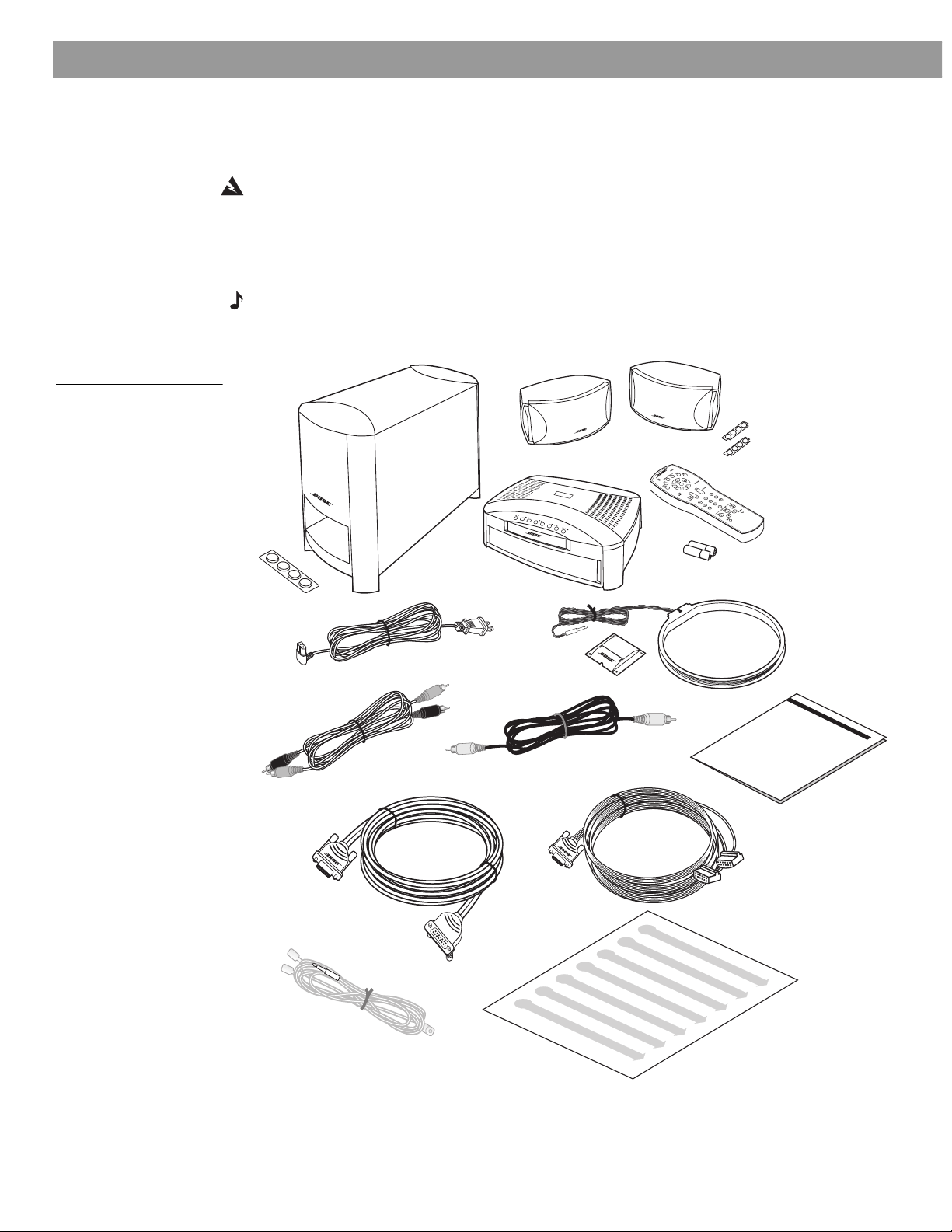
Unpacking
Figure 1
Contents of the shipping
carton
Carefully unpack your system. Save all packing materials, which provide the safest way to
transport your system as needed.
WARNING: To avoid danger of suffocation, keep the plastic bags out of the reach of children.
If any part of the system appears damaged, do not attempt to use it. Notify Bose
®
or your
authorized Bose dealer immediately. For Bose contact information, refer to the address sheet
included in the carton.
Check to be sure your system includes the parts shown in Figure 1.
Note: Now is a good time to find the serial numbers on the bottom of the media center and
Acoustimass
®
module. Copy those numbers onto your warranty card and in the space pro-
vided on page 7.
Speakers
Rubber feet
Module cable
Acoustimass
module
120V power cord
Stereo cable
Rubber feet
Remote
control
Batteries
Media center
Antenna stand
AM antenna
Video cable
Owner’s guide
Speaker cable
FM antenna
Quick setup
guide
8
AM256950_02_V.pdf • January 29, 2002
Page 9
System Setup
Selecting locations for your Model 3•2•1 speakers and media center
Use the following guidelines to choose locations and positions for the speakers and media
center.
Note: While these guidelines are offered to ensure the best system performance, you may
find other placement variations that are more convenient and provide the sound you enjoy.
Keep in mind that the media center connects to both speakers and to the Acoustimass
ule, while the module is the only part of this system that connects to a power outlet.
Placing the small speakers
Choosing a good location for the speakers will allow you to experience the audio spaciousness and surround effects that your Model 3•2•1 home entertainment system is designed to
deliver.
• Be sure to face each speaker straight ahead (toward the listening area), so it can cover the
broadest listening area (Figure 2).
Figure 2
Placement
®
mod-
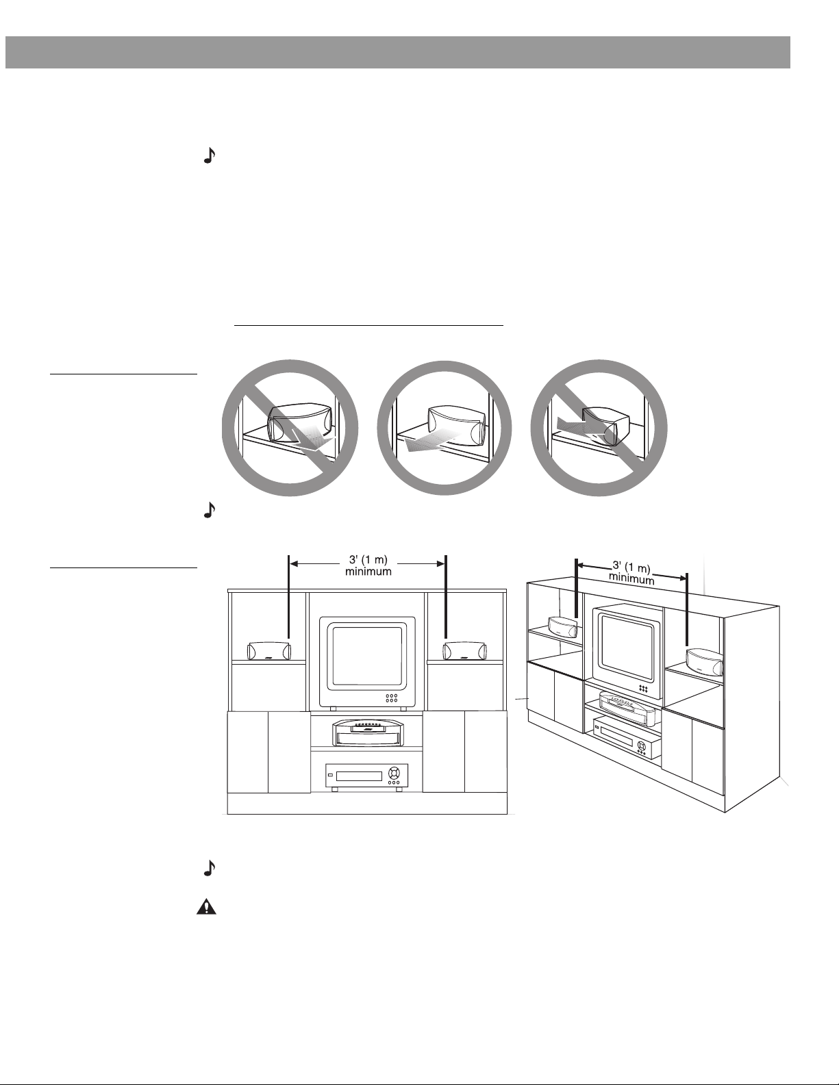
Figure 3
Placement of the small
speakers near a flat wall or
in a corner position
Note: Angling one or both speakers into or away from the listening area significantly alters
system performance.
• If you are using a bookshelf or a home entertainment unit, place each speaker at the front
edge of its shelf .
Note: Positioning these speakers farther back in an enclosed space can change the overall
quality of sound and alter the movie effects.
CAUTION: Choose a stable and level surface for both speakers. Vibration can cause the
speakers to move, particularly on smooth surfaces like marble, glass, or highly polished
wood. If you are placing the speakers on a flat surface, be sure to attach the smaller of the
two sets of supplied rubber feet to the bottom surface. You may obtain additional rubber feet
(part number 178321) from Bose
®
Customer Service. To contact Bose, refer to the list of
offices included in the product carton.
AM256950_02_V.pdf • January 29, 2002
9
Page 10
System Setup
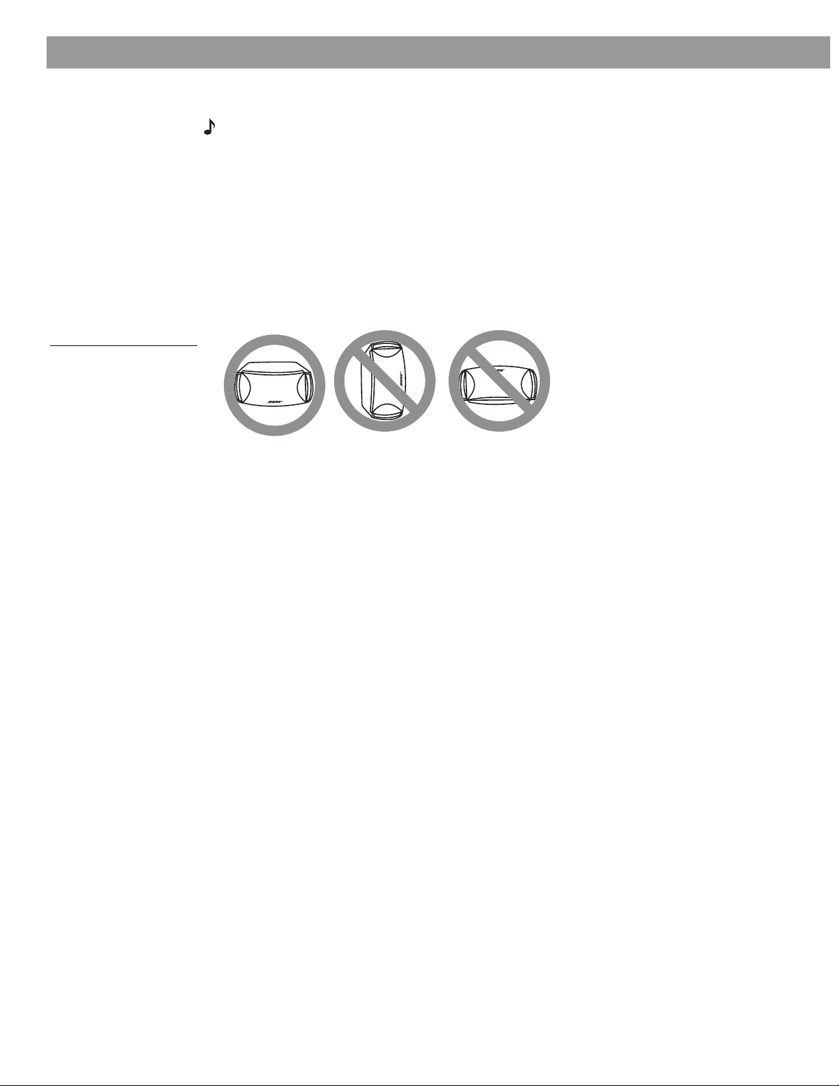
Figure 4
Recommended orientation
of the speakers
• Place the speakers on top of the TV or to the left and right of your TV screen (refer to
Figure 3 on page 9) and at roughly equal distance from it.
Note: The speakers are magnetically shielded to prevent interference when they are on or
near the TV.
• Maintain at least 3 feet (1 meter) of space between the two speakers.
Place the speakers up to 3 feet (1 meter) from the edges of the TV screen.
®
Bose
recommends a maximum distance of 3 feet from each speaker to the edge of the TV
screen to prevent the sound from becoming too separated from the picture. You may vary
this distance, however, based on room conditions and your personal preference.
• Keep both speakers at approximately the same height.
The small speakers are designed to sit only on their bottom surface (Figure 4). In that position
(with the Bose logo right side up), they can also be mounted on optional Bose brackets, table
stands, or floor stands. For details and ordering information, refer to Accessories on page 40.
Media center placement
Place the media center where nothing obstructs opening the disc tray on its front panel.
Be sure it is within reach of the cables connected to the Acoustimass
ers. Make sure it is close enough to additional source components (TV, tape player, VCR) for
all the cables to reach.
If additional audio cables are needed for these connections, contact Bose or your dealer. To
contact Bose, refer to the list of offices included in the product carton.
®
module and the speak-
10
AM256950_02_V.pdf • January 29, 2002
Page 11
A
C
I
N
P
U
T
M
U
S
IC
C
E
N
T
E
R
System Setup
Figure 5
3-foot distance between
the Acoustimass module
and the TV
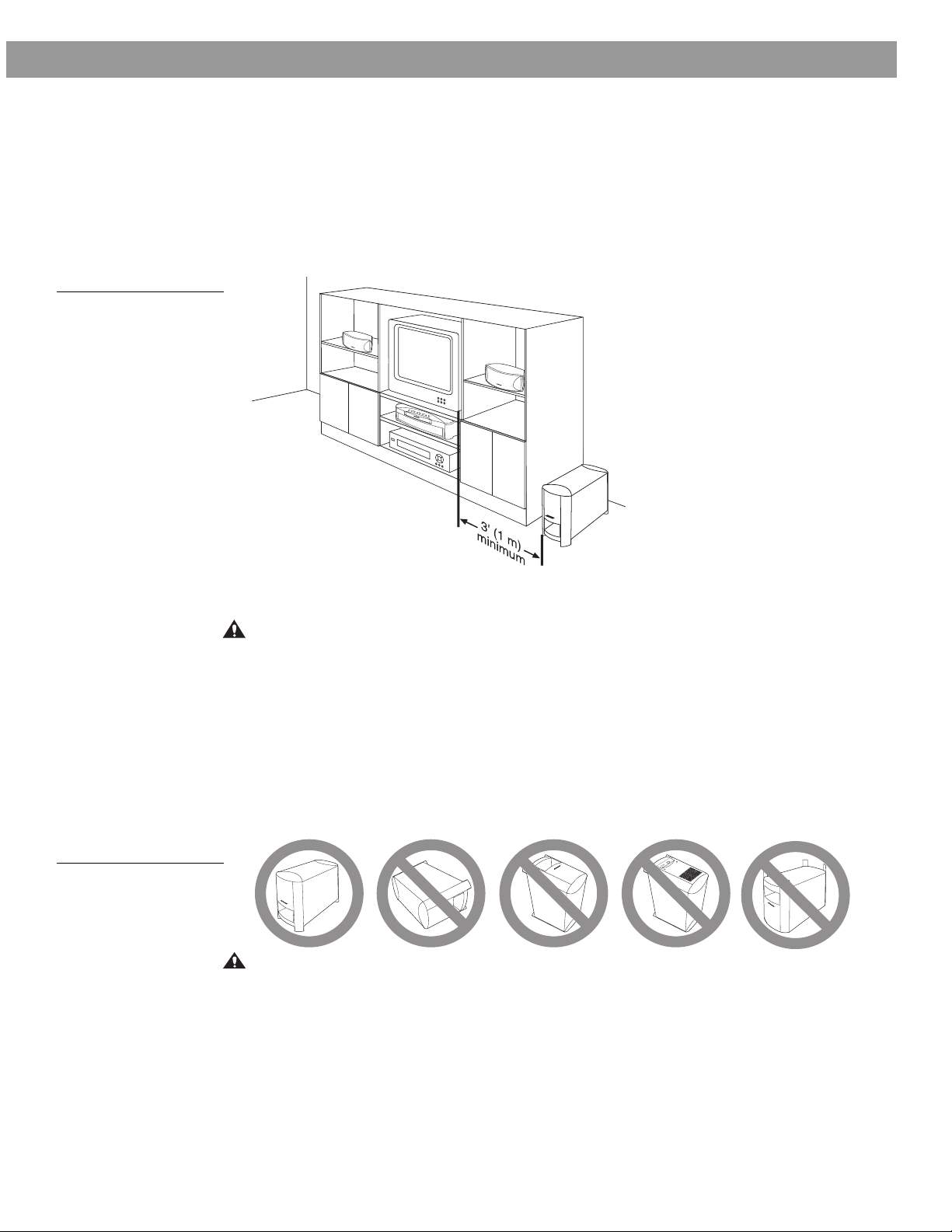
Placement choices for the Acoustimass
®
module
Consider the guidelines below when choosing a location for the module.
Make sure to place it:
• within reach of the cables to the music center and an AC (mains) power outlet
• at the same end of the room as the TV and the speakers (Figure 5)
• a minimum of 3 feet (1 meter) from the TV to prevent interference from the module, which is
not magnetically shielded
Figure 6
Recommended orientation
for the module
Attach the medium-sized rubber feet to the bottom of each foot on the module. The rubber
feet provide increased stability and protection from scratches.
CAUTION: The Acoustimass module generates a magnetic field. Although this is not an
immediate risk to your video tapes, audio tapes, and other magnetic media, you should not
store any of these items directly on or near the module.
Keep the port and ventilation openings free and unimpeded:
• Choose a location that is convenient (under a table, behind a sofa or chair, screened by
drapes) but will not block the ventilation openings of the module.
• Aim the port of the module into the room or along the wall. This prevents a blocked port or
over-powering bass.
• Stand the Acoustimass module on its feet. Do not lay it on its side or stand it on either end
(Figure 6).
CAUTION: Do not block the openings on the back of the module, which provide ventilation
for the built-in circuitry.
AM256950_02_V.pdf • January 29, 2002
11
Page 12
System Setup
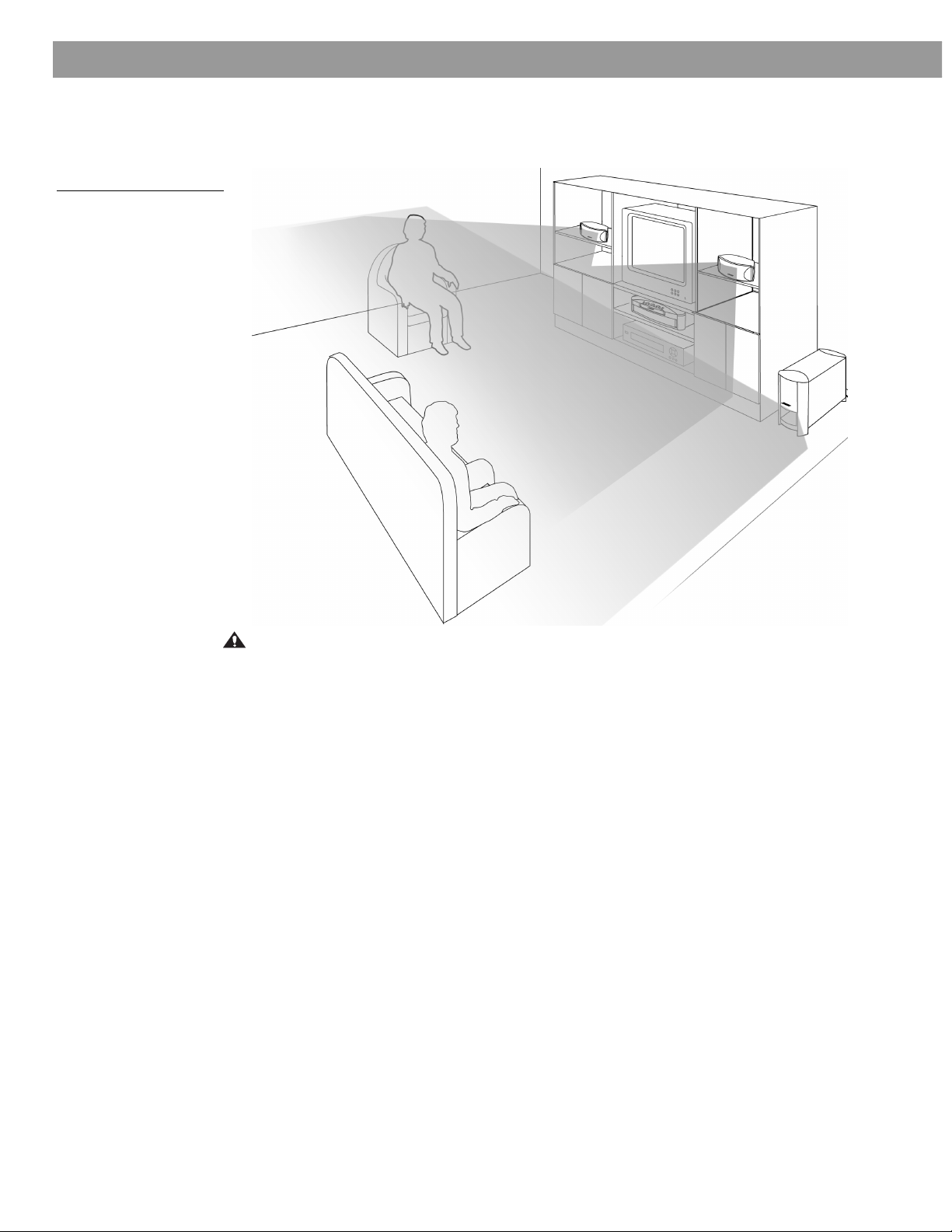
Figure 7
System placement for ideal
coverage
When the system setup is completed
With the speakers and media center placed as directed, you can enjoy the freedom to sit,
recline, or move about in the room without missing a note.
CAUTION: Be sure to read the section on making connections before you plug in the system.
12
AM256950_02_V.pdf • January 29, 2002
Page 13
Making the connections
L L
R
D
D
LRC
S
CSL
R
VIDEO 1 VIDEO 2 AUX
AUDIO INPUT
AUDIO
OUTPUT
VIDEO
OUTPUT
VIDEO
INPUT
OPTICAL
75
Ω
FM
ANTENNA
AM
LOOP
ANTENNA
SPEAKERS
ACOUSTIMASS
MODULE
D
R
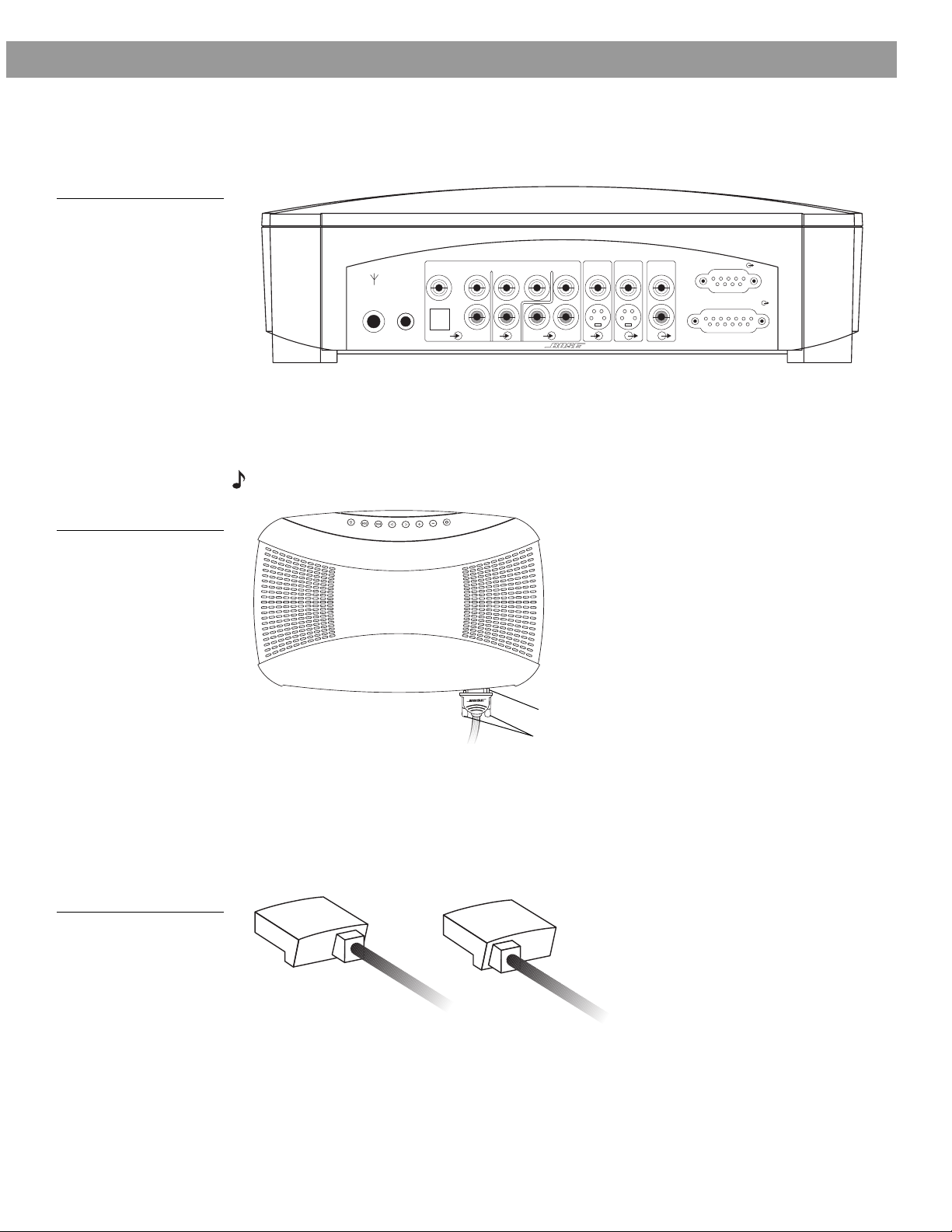
Labeled jacks on the rear of the media center (Figure 8) and the custom cables supplied with
the Model 3•2•1 system make it easy to get everything hooked up right the first time.
Figure 8
Connection panel on the
rear of the media center
Follow these basic steps
1. On the rear panel of the media center, insert the single-plug end of the speaker cable into
the SPEAKERS connector (Figure 8). Tighten the screws on either side of the plug to
ensure a snug connection (Figure 9).
System Setup
Figure 9
Completed connection of
speaker cable to media
center rear panel
Figure 10
LEFT and RIGHT markings
on the speaker connectors
Note: When properly inserted, there will be a small gap between the plug and the panel.
P
t
c
e
j
E
/
p
o
t
S
n
a
c
S
/
p
i
k
S
e
c
r
o
w
e
r
V
o
l
u
m
e
S
o
u
Gap
Screws
2. At the other end of the speaker cable, grasp the two connectors and pull the cable apart
as much as necessary to reach each speaker.
3. Plug the LEFT connector of the separated cable into the rear jack on the left speaker (to
the left of the TV as you face it) and the RIGHT connector into the rear jack on the right
speaker (to the right of the TV). LEFT or RIGHT is printed on the appropriate connector
(Figure 10).
RIGHT
LEFT
AM256950_02_V.pdf • January 29, 2002
13
Page 14
System Setup
LRL
R
D
D
LRCSCSL
R
VIDEO IDEO 2 AUX
AUDIO INPUT
AUDIO
OUTPUT
VIDEO
OUTPUT
VIDEO
INPUT
OPTICAL
75
Ω
FM
ANTENNA
AM
LOOP
ANTENNA
SPEAKERS
ACOUSTIMASS MODULE
D
AC INPUT
MUSIC CENTER
RIGHT
LEFT
Speaker
cable
Acoustimass
module cable
video input
To TV
AC input
VIDEO OUTPUT
jack
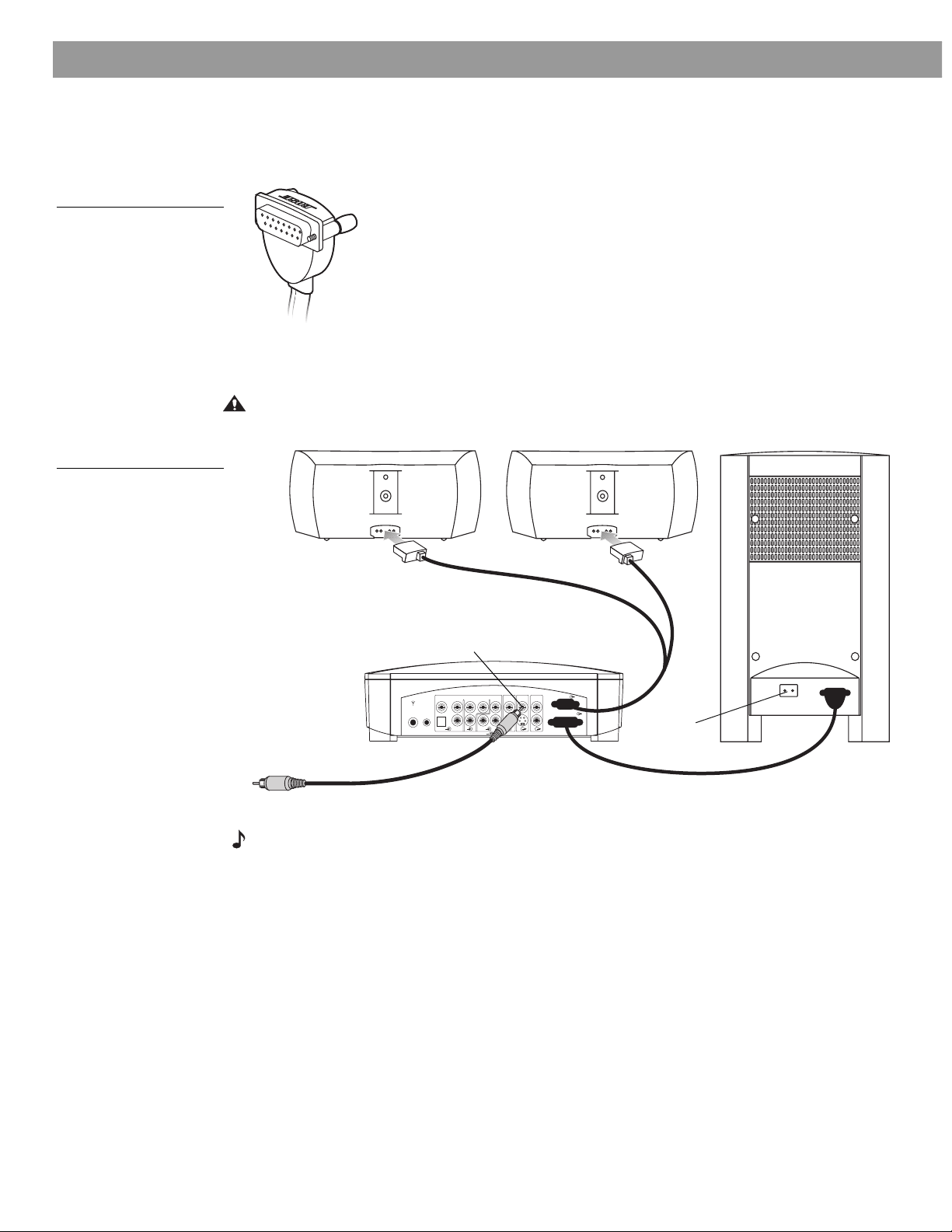
Figure 11
Right-angle connector that
attaches to the Acoustimass module
Figure 12
Basic connections to the
media center
4. On the Acoustimass® module, insert the right-angle connector (Figure 11) of the Acousti-
mass module cable into the jack labeled MEDIA CENTER. On the rear panel of the media
center, insert the other end of the cable into the jack labeled ACOUSTIMASS MODULE.
Firmly tighten the two screws at each end of the cable.
5. On the rear panel of the media center, insert one end of the supplied video cable (marked
in yellow) to VIDEO OUTPUT (Figure 12). Insert the other end of the cable into the video
input on your TV.
CAUTION: Do not plug the Acoustimass module into an AC power (mains) outlet until all the
components are connected.
14
Note: Before using your TV to play a DVD or other video source, be sure to read the Important Note on page 16.
S-video as an alternate means to connect to the TV
An S-video input jack, provided on many TVs, delivers a higher-quality TV picture than the
composite video output connection shown above.
To make this alternate connection, insert the end of an S-video cable from the TV into the SVIDEO OUTPUT on the media center. This cable may be purchased from your Bose® dealer or
a local electronics retailer.
AM256950_02_V.pdf • January 29, 2002
Page 15

Figure 13
Typical arrangement of
components connecting to
the media center
System Setup
Connecting other sources
You can connect both the audio and video outputs of a VCR or other video source to the
media center. A video connection will pass signals through to the TV.
A typical arrangement of components is shown in Figures 13 through 15. For additional
examples of how these connections can be made, refer to “Other choices” on page 19.
Input from cable
audio & video
Cable/sat
audio & video
video
audio
audio
audio
video
VCR
TV
Other component connections
You can connect the audio output of up to three components, including your TV, directly to
the media center using the Video 1, Video 2, and Aux input jacks on the rear panel.
Each input includes jacks for Left and Right analog audio and a coaxial jack for digital audio.
In addition, the Video 1 input provides an optical jack for digital audio.
The jacks marked VIDEO 1 and VIDEO 2 are set automatically for movie EQ. If you connect a
video source to AUX, you can still set sound for movie EQ in the Settings on-screen menu.
When connecting a component’s audio to the media center jacks, remember to:
• use standard RCA audio cables
• match the red connector to the right channel (R) and the white (or black) connector to the
left channel (L)
• use a Y-adapter (available at electronics stores) to connect to a mono source
For further details on making the video connections between your VCR and TV, refer to the
manuals for those video components.
When all the components are connected to the media center, you can add the antennas and
then plug in the system.
AM256950_02_V.pdf • January 29, 2002
15
Page 16

System Setup
Figure 14
Connecting the Audio output from the TV to the
VIDEO 1 input on the media
center
Connecting your TV to the system
The type of video connection used with your TV (Figure 14) must match the type of connection used with your VCR. If you connected your TV to the COMPOSITE VIDEO OUTPUT
(using the cable with a yellow connector at each end), connect your VCR output to the COMPOSITE VIDEO INPUT. If you connected your TV to the S-VIDEO OUTPUT, connect your VCR
to the S-VIDEO INPUT. If your VCR does not have an S-VIDEO output, you may be able to
connect your VCR composite video output directly to your TV.
ANTENNA
75
FM
Ω
LOOP
ANTENNA
VIDEO 1 VIDEO 2 AUX
D
AM
OPTICAL
LRL
AUDIO INPUT
R
D
D
VIDEO
INPUT
LRCSCSL
VIDEOINAUDIO
OUT
AUDIO
VIDEO
OUTPUT
OUTPUT
Media
center
L
R
TV
ACOUSTIMASS MODULE
R
SPEAKERS
Supplied video cable
TV/VIDEO,
INPUT, or
AUX IN
RCA cable
TV/VIDEO
TV remote
Important Note: Your television must be set for VIDEO INPUT when playing a DVD or other
video source. If it is not set properly, you may hear the sound, but will not see the DVD picture
on the TV screen.
For most TV models*, there is a button labeled either “TV/VIDEO,” “INPUT,” or “AUX IN” (or a
similar term) for you to use. When the video input is correctly selected, the word “VIDEO,”
“AUX,” or “LINE IN” usually appears in a corner of the TV screen.
If you are unable to locate the video input of your television, please consult the manufacturer
of your TV.
Also note: Some older TVs, which include a standard TV cable connector, have neither a
composite video nor an S-Video input. Such TVs are not compatible with any DVD players
and require use of an RF modulator for this connection, which is available at your local electronics store.
Connecting your VCR to the system
The type of video connection used with your TV and VCR (Figure 15 on page 17) must match
the type of connection used with your cable/satellite box. If you connected your TV to the
COMPOSITE VIDEO OUTPUT (using the cable with a yellow connector at each end), connect
your cable/satellite box output to the COMPOSITE VIDEO INPUT on your VCR. If you connected your TV to the S-VIDEO OUTPUT, connect your cable/satellite box to the S-VIDEO
INPUT on your VCR.
16
*Other TV models (in particular, some GE/RCA/Proscan models) assign the video input to
channel 00 or 91, so you need to select that channel to receive the video input.
AM256950_02_V.pdf • January 29, 2002
Page 17

Figure 15
R
L
VIDEO
OUT
AUDIO
OUT
LRL
R
D
D
LRCSCSL
R
VIDEO 1 VIDEO 2 AUX
AUDIO INPUT
AUDIO
OUTPUT
VIDEO
OUTPUT
VIDEO
INPUT
OPTICAL
75
Ω
FM
ANTENNA
AM
LOOP
ANTENNA
SPEAKERS
ACOUSTIMASS MODULE
D
Media
center
VCR
RCA cable
Video cable
LRL
R
D
D
LRCSCSL
R
VIDEO IDEO 2 AUX
AUDIO INPUT
AUDIO
OUTPUT
VIDEO
OUTPUT
VIDEO
INPUT
OPTICAL
75
Ω
FM
ANTENNA
AM
LOOP
ANTENNA
ACOUSTIMASS
SPEAKERS
MODULE
D
L
R
VIDEO
A
OPTICAL
75
Ω
FM
ANTENNA
AM
LOOP
ANTENNA
D
FM
AM
Connecting audio output
from a VCR to the VIDEO 2
input on the media center,
and the video from the VCR
to the composite video
input on the media center
System Setup
Note: Do not connect the video output of your 3•2•1 system media center to a VCR; playing
copy-protected DVDs may result in poor picture quality.
Attaching the supplied antennas
The rear panel of the media center provides jacks for AM and FM antennas (Figure 16).
Unwind the wires of each antenna to ensure the best reception.
Note: An outdoor antenna may be used in place of the two that are supplied. To add an outdoor antenna, consult a qualified installer. Follow all safety instructions supplied with the
antenna.
Figure 16
Adding the AM and FM
antennas
FM antenna
Plug the connector into the FM antenna jack on the media center rear panel. Spread out the
antenna arms at the other end and move them around to establish optimum FM reception.
Extend the antenna as far from the media center and other external equipment as possible.
AM antenna
1. Plug the connector into the AM antenna jack on the media center.
2. Move the antenna loop as far as possible, at least 20 inches (50 centimeters) from the
media center and at least 4 feet (1.2 meters) from the Acoustimass® module. Experiment
with positioning the loop for optimum AM reception.
3. Follow the instructions enclosed with the AM loop antenna to stand it on the supplied
base, or mount it to a wall.
AM256950_02_V.pdf • January 29, 2002
17
Page 18

System Setup
AC outlet
Figure 17
Power cord as the final
connection
Connecting cable FM radio
Some cable TV providers make FM radio signals available through the cable service to your
home. This connection is made to the external FM jack on the back panel of the media center.
To connect to this service, contact your cable TV provider for assistance.
Note: Make sure that the cable radio installation includes a signal splitter so that only the FM
radio band, not the cable TV band, is received by the media center. If necessary, contact a
qualified installer.
Make the power connection after all the others
To make the final connection, insert the small connector end of the power cord into the AC
INPUT jack on the module (refer to Figure 12 on page 14). Insert the large end of the cord into
an AC power (mains) outlet (Figure 17).
Turning off the internal speakers in your TV
When you listen to TV sound through your 3•2•1 system, the speakers in your TV should not
be on. Use the on-screen menus in your TV to select INTERNAL SPEAKERS: OFF (the exact
on-screen message may be different for different TVs). Refer to your TV owner’s guide for
detailed instructions.
If your TV does not have an option to turn off the internal speakers, you can reduce the volume of your TV to its lowest setting.
18
AM256950_02_V.pdf • January 29, 2002
Page 19

Installing remote control batteries
1. On the back of the remote, slide open the battery compartment (Figure 18).
2. Insert the two supplied AA (IEC-R6) 1.5V batteries, or their equivalent, as shown. Match
the plus (+) and minus (–) marked on the batteries with the plus (+) and minus (–) inside
the battery compartment.
3. Slide the battery compartment cover back into place.
Note: Replace the batteries when the remote control stops operating or its range seems
reduced.
System Setup
Figure 18
Installing the batteries
Other choices
Figure 19
The media center receives
audio signals from the cable
or satellite box and the
VCR, but not from the TV
AA batteries
Battery
compartment cover
The 3•2•1 system is designed to deliver high-quality home entertainment free of complexity
and complications. But it also provides the flexibility for you to add other components in a
variety of configurations.
The following illustrations show two additional means of connecting equipment to the media
center.
In Figure 19 below, both audio and video from a cable or satellite box are routed through the
VCR. Audio from the VCR is connected to the media center, while the TV audio is not. Any
non-cable/satellite TV sound comes directly from the TV, while you enjoy the benefits of
®
sound with any cable/satellite or VCR programs.
Bose
Input from cable
audio & video
Cable/sat
audio & video
video
audio
audio
VCR
video
AM256950_02_V.pdf • January 29, 2002
TV
19
Page 20

System Setup
In Figure 20, the audio from both the cable or satellite box and the VCR is routed to the TV,
and the TV audio is connected to the media center. This delivers all of the video source sound
through one jack (for instance, VIDEO 1) on the media center. This allows you to use just one
button on your remote to select the sound from any video program you play.
Figure 20
The media center receives
all audio-for-video signals
directly from the TV
Figure 21
Record/playback connections
Input from cable
audio & video
Cable/sat
audio & video
video
audio
audio
audio
VCR
TV
video
Connecting recording equipment
The rear panel of the media center provides audio output (RECORD) connections for audio
recording (Figure 21).
75
ANTENNA
AUDIO INPUT
VIDEO I VIDEO 2
D
LRL
AM
Ω
FM
LOOP
ANTENNA
OPTICAL
AUX
D
LRC
R
D
AUDIO
VIDEO
VIDEO
OUTPUT
INPUT
CSL
S
OUTPUT
R
SPEAKERS
ACOUSTIMASS
MODULE
Media center
RECORD
INPUT
L
R
Recording component
20
AM256950_02_V.pdf • January 29, 2002
Page 21

Figure 22
AUX input connections
System Setup
Connecting other playback equipment
Other playback components, such as an audio CD changer, can be connected to the AUX
inputs on the rear panel of the media center (Figure 22).
AUDIO INPUT
75
FM
ANTENNA
VIDEO I VIDEO 2 AUX
D
AM
Ω
LOOP
ANTENNA
OPTICAL
LRL
D
LRC
R
D
S
AUDIO
OUT
L
R
Connecting digital audio components
Your other audio components may feature a digital audio output. If so, you can connect an
optical output to the OPTICAL jack of the VIDEO 1 INPUT or a coaxial output to the coaxial
jacks of VIDEO 1, VIDEO 2, or AUX on the rear panel of the media center. Use an optical digital cable or coaxial cable to make these connections.
Note: The digital audio inputs of this system are not able to decode a DTS bitstream from an
external component.
AUDIO
VIDEO
VIDEO
OUTPUT
OUTPUT
INPUT
CSL
AUX component
SPEAKERS
MODULE
ACOUSTIMASS
R
Media center
AM256950_02_V.pdf • January 29, 2002
21
Page 22

Controls, Displays, Menus
On/Off controls
Press the On/Off button on the remote to turn the media center on. The Power button on top
of the media center performs the same function.
To turn on components connected to the media center, use the remote for that specific component or its power switch.
Note: Neither the Model 3•2•1 remote nor the media center can switch components, such as
the TV or VCR, on or off. However, a universal remote (new enough to include codes for the
Bose Model 3•2•1 system) or programmable “learning” remote can control this system.
The remote control
Buttons on the remote control are grouped according to function. Other buttons on the media
center provide some of the same controls as described below.
POWER and MUTE controls
Switches the system on or off.
Mutes/unmutes the system volume.
SOURCE controls
Selects the built-in CD/DVD player and turns the system on.
Unmutes the system volume.
Selects AUX as the sound source and turns the system on.
Unmutes the system volume.
Selects Video 1 as the sound source and turns the system on.
Unmutes the system volume.
Selects Video 2 as the sound source and turns the system on.
Unmutes the system volume.
Selects the built-in tuner and turns the system on to the previouslyselected AM station.
Unmutes the system volume.
Selects the built-in tuner and turns the system on to the previously-
selected FM station.
Unmutes the system volume.
22
AM256950_02_V.pdf • January 29, 2002
Page 23

SOURCE and MENU controls
Tunes the AM/FM radio up/down to the next higher/lower frequency.
In an on-screen menu, selects the next item, up or down.
Seeks forward/backward to the next strongest radio station.
In an on-screen menu, changes the setting of a selected menu
item.
Enters submenus. Also submits custom settings, choices, or
entries in conjunction with other buttons.
Displays the menu of the DVD disc currently loaded in the tray, as
the particular DVD allows.
Displays or exits the Bose 3•2•1 system on-screen menus.
Controls, Displays, Menus
Skips to the next/previous DVD chapter, radio station preset, or
CD track.
Raises or lowers the system volume.
+ Unmutes the system volume. Raises the volume.
– Lowers the system volume while it is muted.
1203
456
789
Each button gives you access to a similarly numbered DVD chapter, CD track, or radio station preset.
When selecting numbers 1 through 9, entering a zero before the
number ensures the fastest response.
PLAYBACK controls
Stops the disc player and, for DVDs only, temporarily holds the
place where the disc stopped. Press Stop again and the player
moves to the beginning of the disc.
Pauses the disc player in place. After 20 minutes, switches to
Stop.
Starts the disc player.
Scans back or forward for DVD chapters, CD tracks, or the next
strongest radio station.
Plays audio CD tracks (not DVD chapters) in varied order. Press
again to cancel this mode.
Repeats a CD, CD track, DVD chapter, or DVD title until the button is pressed again.
AM256950_02_V.pdf • January 29, 2002
23
Page 24

Controls, Displays, Menus
P
o
w
e
r
V
o
l
u
m
e
S
o
u
r
c
e
S
k
i
p
/
S
c
a
n
S
t
o
p
/
E
j
e
c
t
Preset
station
selected
SETTINGS
TITLE
VIDEO 1 VIDEO 2AUX
FMAM
CD
SHUFFLE
STEREO
RDS
REPEAT
DISC
REPEAT
TRACK
TRACK SLEEP
ANGLECHAPTER
DVD
MOVIE EQ
PRESET
Source indicators
(The selected source appears in an outlined box.)
CD/DVD play
selected
Movie equalization
mode selected
Sleep mode
selected
FM stereo
indicator
RDS indicator
(Europe only)
Settings mode
selected
CD/DVD
play
paused
Number
of preset
selected
DVD camera
angle selected
8-digit display
CD play
mode
indicators
DVD chapter
CD track
selected
Movie title
selected
or title
The media center
The media center has a control panel on the top, a display area on the front that indicates the
current status of the system, and a DVD/CD tray that opens on the front of the console.
Control panel and buttons
The media center has eight buttons located on the top control panel. Their functions are also
provided through use of the remote control.
Turns the system on or off.
Raises/lowers the volume. Pressing + unmutes the
system.
Figure 23
All of the possible symbols
that may appear, depending
on the current status of the
system
Moves from one source selection to the next.
Selects the previous/next DVD chapter or CD track or
scans to previous/next strongest radio station.
In AM or FM mode: tap to seek a radio station;
hold down to tune to a station.
In CD/DVD mode: tap to skip tracks or chapters; hold
down to scan them.
Opens/closes the disc tray.
Display indicators
With the system turned on, the music center display lights up to show the current system status. Not all of the possible choices shown below will light up at once (Figure 23). The display
changes with each adjustment or selection you make.
24
AM256950_02_V.pdf • January 29, 2002
Page 25

TV on-screen menus
Submenu – This symbol indicates that there
is a submenu of items for this selection.
Press the Enter button to enter the submenu.
Settings (DVD)
DVD Play Options
Audio Setup
System Setup
Lists options for how to play and view the current DVD.
select item
Title bar – Shows the name of the menu
or submenu you are using (the currently
selected source is in parentheses).
Menu items – Source-related set-
tings and submenus appear in this
space.
Selected menu item – Menu items are selected
(highlighted) with the Tune up/down keys.
Menu item description – Describes the
selected menu item.
Navigation controls – Identifies which remote
control buttons to use within the displayed menu.
Status display area – Displays sta-
tus information when a status item is
selected.
goes to submenu
DVD Status:
Sleep Timer: Off
With both the TV and the Model 3•2•1 system turned on, you can use menus that appear on
the TV screen to choose among options for audio and video performance.
To enter the Settings menu
Press the Settings button on the remote. The displayed menu will contain items related to the
currently selected source. For example, if you press Settings while watching a DVD, you will
see a menu similar to the one in Figure 24.
To leave the Settings menu
Press the Settings button again. The on-screen menu disappears.
Figure 24
Elements of the on-screen
menu displays
Controls, Displays, Menus
To select a menu item
Use the remote control Tune or , Seek or , and Enter buttons (as described on
page 23) to move through these menus and make selections, as shown in Figure 24.
AM256950_02_V.pdf • January 29, 2002
25
Page 26

Controls, Displays, Menus
DVD Play Options (1 of 2)
Title: 1 of 3
Chapter: 23 of 30
Title Time: 0:23:02
Time Display: Elapsed
Motion Control: Play 1x
Chooses an audio track for the current DVD.
select item
Camera Angle: 1 of 1
More…
Audio Track: English 2222 D 5.1 ch
change setting
Chapter: 1 of 19
To change a setting
Figure 25
Example of changing
a setting
To check the system status
Figure 26
A DVD status example
Settings (DVD)
DVD Play Options
Sleep Timer:
DVD Status:
Audio Setup
System Setup
Displays information about the current source.
select item
DVD
Playing
The Movie Title
Title 1 of 13
Chapter 1 of 5
Title Total 0:00:00
Audio English 2222 D 5.1 ch
Subtitle Off
Ratings Limit: 8
Region Code:1
26
AM256950_02_V.pdf • January 29, 2002
Page 27

Turning your system on and off
You can turn your system on and off using the On/Off button ( ) on the remote control or
the power button ( ) on top of the media center. When you turn it on with either button, the
source that was played last is automatically selected.
You can also press any source button on the remote to turn the system on and select the
source at the same time.
Before you play your first DVD
Before you play the first DVD, make sure:
• that you are familiar with how the system remote control operates (as explained on page
22).
• the region codes for the DVD player and disc match, as explained on page 5 of this guide.
(Check the region code number on the media center label or on the shipping carton.)
• the TV is properly set for video input from the DVD player (see the Important Note on page
16).
Before you select some system features, you also may want to confirm that the disc is
encoded for that feature. For example, in order to display subtitles while watching a movie,
the disc must contain subtitle information.
Operation
Loading and playing a DVD
1. Turn your television and Model 3•2•1 system on.
2. On the remote, press the CD/DVD button.
3. On the media center control panel, press the Stop/Eject button.
4. Place the DVD disc in the open media center tray.
5. Press the Stop/Eject button again to close the tray.
The DVD disc begins to play automatically. If it does not, press Play on the remote.
Basic DVD operations
If you want to: Use the remote to do this:
Pause a DVD movie… Press Pause
Stop a DVD movie… Press Stop
Skip to the next/previous
chapter…
Press Chapter up/down.
Repeat a chapter… Press Repeat while playing the chapter.
Search through the movie
backward or forward…
AM256950_02_V.pdf • January 29, 2002
Press and hold Scan or
27
Page 28

Operation
Using the Parental Control feature to restrict future play
You can restrict playback of DVD movies by setting the level of Parental Control.
The levels match ratings on each DVD that are equivalent in many cases to standard movie
ratings provided by the Motion Picture Association of America (MPAA). These levels range
from 1 (most restrictive) to 8 (least restrictive). By storing a password in the system, you can
prevent any changes to the Parental Control setting or the viewing of movies rated above the
control level without use of the password.
For information on where to find and how to use the Parental Control option, refer to the System Adjustments section on page 35.
DVD-specific behavior
When you select features from any options menu while watching a movie, the movie may
stop, skip forward, or skip back. This behavior is determined by the DVD you are playing and
does not indicate a problem with the system.
DVD play options
Settings (DVD)
DVD Play Options
While the system is in DVD mode, press the Settings button on the remote control to
gain access to the options shown here. For more details on changes you can make to the
settings, refer to the Sound Adjustments and System Adjustments sections of this guide.
Settings: DVD Play Options (1 of 2)
Title:
Chapter:
Title Time:
Time Display:
Motion Control:
Audio Track:
Camera Angle:
More...
Selection: DVD setting options: What the setting affects:
Title: 1 of n Chooses the movie title through use of the number keys.
Chapter: 1 of n Chooses the movie chapter through use of the number keys.
Title Time: h:mm:ss Moves to that time/place in the movie.
Settings: DVD Play Options (2 of 2)
Previous...
Subtitles:
Subtitle Language:
AB Repeat
Time Display: Elapsed
Motion Control: <<Scan/ <<4x/ <<2x/
Pause/ Play1x/ 2x>>/
4x>>/ Scan>>
Audio Track: 1 English 2 5.1 ch
28
Shows how much time the movie has played in the on-screen DVD
status and on the media center display.
Remaining
Shows how much time the movie has left to play in the on-screen
DVD status and on the media center display.
Chooses forward or backward direction and speed for DVD playback.
Chooses from the available soundtracks on the DVD. Additional
2 Lang2
3 etc.
soundtracks may contain different languages or alternate audio
formats.
AM256950_02_V.pdf • January 29, 2002
Page 29

Operation
Camera Angle: 1 of max. Chooses one of the available camera angles on the DVD.
More... selection Displays remaining menu items.
Previous... selection Displays initial menu items.
Subtitle: On
Subtitle Language: Lang1/ Lang2/ etc. Chooses one of the available languages for display of subtitles
AB Repeat selection Repeats a specified section of a movie after prompting you to:
Displays subtitles, if available, along the lower screen edge.
Off
Hides subtitles. For use with Auto subtitles (refer to on page 36).
• Press Enter at the beginning of the section you want to repeat.
• Move forward or back to another point in the film
• Press Enter again.
Replay ends when you press Enter, Play, or Stop.
Loading and playing a CD
1. On the remote, press the CD/DVD button.
2. At the media center, press the Stop/Eject button.
3. Place the audio CD in the open disc tray.
4. Press the Stop/Eject button to close the disc tray.
The CD will start to play automatically. If it does not, press Play .
While playing a CD, the display window on the media center indicates:
• Track number
• Track time
• Repeat or Shuffle mode
Basic CD operations
If you want to: Use the remote to do this:
Pause a CD… Press Pause
Resume play of paused CD… Press Pause again or Play
Stop a CD… Press Stop
Go to next track… Press Track up
Go to beginning of current track… After track has played for several seconds,
press Track down.
Go to a previous track… If track has played for several seconds, press
Track down twice. If not, press once.
Scan a CD backward/forward…
Randomly play CD tracks… Press Shuffle after loading a CD.
Cancel random play… Press Shuffle again, while in that mode.
Press and hold Scan or
AM256950_02_V.pdf • January 29, 2002
29
Page 30

Operation
Selection: CD setting options: What the setting affects:
Changing CD settings
While the system is in CD mode, press the Settings button on the remote control to gain
access to the options shown here. For more details on changes you can make to the settings,
refer to the Sound Adjustments and System Adjustments sections of this guide.
Sleep Timer: Off
mm:ss
Track: 1 of n Chooses the CD track by number.
Track Time: h:mm:ss Moves to that time/place in the track.
CD Status selection Displays information about the CD source.
Audio Setup selection See Sound Adjustments on page 33.
System Setup selection See System Adjustments on page 35.
Timer not set.
Set to turn system off (not the components) when time (01:00 to 90:00
minutes) expires.
Using the sleep timer
Your system includes a sleep timer which can be set to turn your system off automatically
after 1 to 90 minutes of listening to any source. This timer can be accessed through the Settings menu. See “Locating system settings” on page 35.
Note: Remember that system controls, like the sleep timer, will not turn off the TV or other
sound source components.
Using the radio
Press or on the remote to select the radio tuner. If the system is off, this will turn it on
to the most recently selected station in that band.
Tuning
You can tune to a radio station in the following ways:
If you want to: Do this:
Switch bands Press or on the remote for the band you want.
Seek the strongest stations Press and hold Seek or on the remote until the radio
begins seeking. Release to stop at the next strongest station.
To stop sooner, briefly press Seek or .
To begin seeking again without holding down the skip but-
ton, briefly press Seek or again as soon as the first
seek operation stops.
Manually tune to a station Press Tune or on the remote.
Select a preset station Press Preset
or
Press that number on the keypad.
While the system is in AM or FM mode, and the TV is on, you can press the Settings button
on the remote control to gain access to the options available for that band. For more details
on changes you can make to the settings, refer to the Sound Adjustments and System
Adjustments sections of this guide.
30
AM256950_02_V.pdf • January 29, 2002
Page 31

Operation
Storing preferred stations as preset selections
For radio stations that you listen to regularly, you can assign a preset number (1-25 in the AM
band and 1-25 in FM) to tune to them quickly.
To store a particular station:
1. Tune to that station using the Tune, Seek, or Scan buttons on the remote.
2. Press Enter. A preset number blinks while STORE? appears on the media center display.
3. Press Enter to store the station to that blinking number.
Note: If you want to change the station assigned to a particular preset number, you must first
delete the station already assigned to it.
To erase the station assigned to a particular preset number:
1. Tune to the preset station.
2. Press Enter. The preset number blinks while ERASE? appears on the media center dis-
play.
3. Press Enter to remove the station from that assigned preset number.
That number is now available for storing a different station.
Selecting a preset station
You can select preset stations using the remote control or the on-screen settings menu.
To select a preset with the remote control:
• Using the numbered keys on the remote control, press the number(s) for the preset station
you want to hear.
• Press Preset up or down to change the preset number.
To select a preset using the settings menu:
1. Press or on the remote to select the FM or AM source.
2. Press . (Make sure your TV is on.)
3. Press to select Preset.
4. Press / to step through the preset stations.
Changing FM settings
Selection: FM setting options: What the setting affects:
Sleep Timer: Off
mm:ss
Station:
Preset: 1 of 25 Tunes to the stored preset station.
FM Status selection Displays information about the FM source.
RDS info:
(for Europe only)
Output mode: Stereo
Audio Setup selection See Sound Adjustments on page 33.
System Setup selection See System Adjustments on page 35.
----
Mono
Timer not set.
Sets timer to turn off when time (01:00 to 90:00 minutes) expires.
Tunes to that station frequency.
On
Makes RDS information appear in media center display.
Off
Makes RDS information not appear on media center display.
Always plays the FM broadcast in stereo.
Always plays the FM broadcast in mono.
AM256950_02_V.pdf • January 29, 2002
31
Page 32

Operation
Changing AM settings
Selection: AM setting options: What the setting affects:
Sleep Timer: Off
mm:ss
Station:
Preset: 1 of 25
Available only if
presets include
an AM station
AM Status selection Displays information about the AM source.
Audio Setup selection See Sound Adjustments on page 33.
System Setup selection See System Adjustments on page 35.
----
Timer not set.
Sets timer to turn off when time (01:00 to 90:00 minutes) expires. Refer to
“Using the sleep timer” on page 30.
Tunes to that station frequency.
Tunes to the stored preset station.
Playing other sources
Turn on any component connected to the media center by using the remote for that component or controls on the component front panel.
Pressing AUX, Video 1 or Video 2 on the 3•2•1 system remote turns on the system and
selects the audio for that component. Be sure a tape or disc is loaded, as needed.
Use the Volume ▲ or ▼ buttons on the 3•2•1 remote control or media center to raise or
lower the volume of the system.
To control all other functions of that source, use its remote or front-panel controls. For details
on what changes you can make, refer to the owner’s manual that came with the component.
To record to a connected tape deck, play the built-in or connected source (AM/FM, CD, or
AUX) you want to tape. Listen to the speakers to be sure you have selected the audio you
want to tape. Set the tape deck to Record.
Changing settings for the other sources
Selection: Setting options: What the setting affects:
Sleep Timer: Off
mm:ss
VID 1, VID 2, AUX
Status:
Audio Setup selection See Sound Adjustments on page 33.
System Setup selection See System Adjustments on page 35.
selection Displays information about the connected source.
Timer not set.
Sets timer to turn off when time (01:00 to 90:00 minutes) expires. Refer to
details
System settings
When necessary, the system settings can be changed using the System Settings menus. See
“Locating system settings” on page 35.
32
AM256950_02_V.pdf • January 29, 2002
Page 33

Locating Audio Setup
1. Press the Settings button. A menu of the available settings for the current source
2. Using the Tune button, scroll down the list and select (highlight)
3. Press the Enter button and the audio settings will be displayed for the current source.
Sound Adjustments
will be displayed on your TV screen.
Audio Setup.
Settings (DVD)
Audio Setup
Audio Setup menu
Selection: Setting options: What the setting affects:
Movie EQ: On Sets proper equalization for this particular movie.
Range Compression: On
Off
2222 1 + 1: 1 of n Not shown above. Indicates that a Dolby 1+1 audio track is playing.
Mono Decoding: On
Off
Settings: Audio Setup
Movie EQ:
Range Compression:
Mono Decoding:
Audio Status:
Treble Compensation:
Bass Compensation:
Automatically adjusts the volume so you can hear soft sounds (particularly dialogue) and are not overwhelmed by loud special effects,
like an explosion. This feature is normally engaged when you turn
the system on to DVD, VIDEO 1, VIDEO 2, or AUX.
Range compression not active.
Automatically engages Bose® Videostage® decoding circuitry when a
Dolby Digital bitstream indicates that it contains a mono program.
This feature can process a one-channel program in multi-speaker
sound, directing the signals so that dialogue remains locked onscreen, while music and ambient effects fill the room.
Mono decoding not active.
Not available for FM, AM, or CD.
Audio Status selection Displays system audio information. The example in Figure 27 on
page 34 shows the DVD audio status.
AM256950_02_V.pdf • January 29, 2002
33
Page 34

Sound Adjustments
Settings: Audio Setup
Range Compression: Off
Displays information about volume and other
adjustments.
select item
Audio
Volume: 55
Mute: Off
Mono Decoding:
Audio Status:
Bass Compensation: 0
Treble Compensation: 0
Movie EQ: Off
Treble Compensation: –15 to +15 Decreases(–) or increases (+) the treble sound.
Rooms with too few sound-absorbing furnishings, especially those
with bare floors and walls, may sound overly shrill or “bright.” Lowering this setting to a negative value (–1 to –15) decreases the treble
sound.
Rooms with a lot of sound-absorbing furnishings, such as upholstered furniture, wall-to-wall carpet, or heavy drapes, may reduce
the treble sound of your system. Moving speakers farther away from
soft furnishings increases treble. You can also increase the treble
sound by raising this setting to a positive value (+1 to +15).
Bass Compensation: –15 to +15 Decreases (–) or increases (+) the bass sound.
Placement of the Acoustimass® module affects the amount of bass
you hear. Placing the module closer to the corner of the room will
increase the bass. Moving the module away from the corner will
decrease the bass.
You can also decrease the bass sound by lowering this setting to a
negative value (–1 to –15). To increase the bass, raise this setting to
a positive value (+1 to +15).
Figure 27
DVD audio status
34
AM256950_02_V.pdf • January 29, 2002
Page 35

Locating system settings
1. Press the Settings button. A menu of the available settings for the current source
will be displayed on your TV screen.
2. Using the Tune button, scroll down the list and select (highlight)
System Setup.
3. Press the Enter button and the System Setup will be displayed.
Settings (DVD)
System Setup
Settings: System Setup
Display Language:
DVD Setup
Video Format:
System Adjustments
System Setup: DVD Setup
Auto Subtitle:
Video Black Level:
Available only
after password
has been entered.
If you forget your password, contact Bose Customer Service for assistance.
*
Refer to the Bose address list enclosed with this system.
DVD Autoplay:
Aspect Ratio:
Image Format:
Parental Control Setup
Parental Control Setup
Restrict Unrated Titles:
Change Password
Allowed Ratings:
Restrict Unrated Titles:
Change Password
Confirm Password
*
- - - -
AM256950_02_V.pdf • January 29, 2002
35
Page 36

System Adjustments
System Setup menu
The System Setup menu lists options for how to set up the entire system.
Selection: Setting options: What the setting affects:
Display Language: English/French/
Spanish/etc.
DVD Setup selection Provides a selection of options, including Parental Control, for the
Video Format: NTSC
PAL
Video Black Level: Normal
Extended
DVD Setup submenu
The DVD Setup submenu lists options for how the DVD player should operate, including
Parental Control.
Selection: Setting options: What the setting affects:
Auto Subtitle: On
Off
DVD Autoplay: On
Off
Presents on-screen display menus in the selected language.
DVD.
Sets video format to the USA standard.
Sets video format to the European standard.
Sets black level required for most TVs.
Sets black level that may be appropriate for DVD playback.
Subtitles, if available on the particular DVD, are automatically displayed when the audio is muted.
DVD subtitles are not displayed automatically.
DVD starts to play automatically when it is loaded into the DVD
player.
DVD is not started automatically when loaded.
Aspect Ratio: 4:3
16:9
Image Format: Pan & Scan
Letterbox
Parental Control Setup selection Provides access to the Parental Control submenu.
Provides the DVD aspect ratio for standard (4:3) TVs.
Provides the DVD aspect ratio for widescreen (16:9) TVs.
Images are sized to fit a standard TV, if the particular DVD allows it.
Images are presented in Letterbox format if the particular DVD
allows it (with black bars at the top and bottom of the screen).
If Aspect Ratio is 16:9, Image Format is not applicable and the
setting is automatically shown as “--”.
36
AM256950_02_V.pdf • January 29, 2002
Page 37

Parental Control submenu
The parental control submenu provides options for restricting access to certain DVDs.
Selection: Setting options: What the setting affects:
System Adjustments
Restrict Unrated Titles: On
Change Password: – – – – Lists options for how to create a new password or to change a cur-
Allowed Ratings: 1 to 8* Blocks access to DVDs rated higher than the limit. Rating 8 means
Prevents viewing of unrated titles when password is set.
Off
Allows unrated titles to play.
rent password. Passwords cannot be deleted.
If you forget your password, contact Bose Customer Service for assistance. Refer to the Bose address list enclosed with this system.
no restriction.
DVD Rating General Description of Rating MPAA Rating
*8 Unrated (generally most restricted)
7 Adult audiences NC-17
6 Mature audiences R
5 Mature teenage audiences
4 Teenage audiences PG-13
3 Mature young audiences PG
2 Most audiences
1 General (unrestricted audiences) G
AM256950_02_V.pdf • January 29, 2002
37
Page 38

Reference
AA batteries
Battery
compartment cover
Taking care of your 3•2•1 home entertainment system
Caring for your system may include cleaning the system’s enclosures, cleaning your discs,
and replacing the remote control batteries.
Cleaning the media center
• Use only a soft, dry cloth to clean the outside surfaces of the media center.
• Do not use any sprays near the system. Do not use any solvents, chemicals, or cleaning
solutions containing alcohol, ammonia, or abrasives.
• Do not allow any liquids to spill into any openings.
Cleaning the speakers
• Clean the surface of your speakers with a soft, damp cloth. You can use an ammonia-free
window cleaner on a soft cloth to maintain the finish.
• Do not use any sprays near the speakers. Do not use any solvents, chemicals, or cleaning
solutions containing alcohol, ammonia, or abrasives.
• Do not allow liquids to spill into any openings.
• The speaker grilles require no special care, although you may vacuum them carefully, if nec-
essary.
Figure 28
Disc care
Cleaning discs
• Handle discs by their edges to prevent fingerprints and scratches (Figure 28a).
• To remove stains or fingerprints from the surface of a disc, use a soft and dry lint-free, cloth.
Wipe in straight movements from the center of the disc to the outside (Figure 28b). Do not
use any chemical products; they can damage the disc.
• Do not use a circular motion to clean (Figure 28c).
• Do not write on or attach labels to the surface of a disc.
• To minimize exposure to dust and dirt, return discs to their cases after use. Store each disc
in its case, away from direct sunlight, high temperatures, and humidity.
a.
b. c.
Replacing the remote batteries
Slide open the battery compartment (Figure 29).
Notice the polarity markings (+ and –) inside the compartment and install the batteries
accordingly. Slide the battery compartment cover back into place.
Figure 29
Putting in the batteries
38
AM256950_02_V.pdf • January 29, 2002
Page 39

Troubleshooting
Problem What to do
Reference
System doesn’t do anything
No sound • Increase the volume.
Sound but no picture • Make sure the TV is on.
• Make sure the unit is turned on.
• Make sure the power cord is inserted securely into the Acoustimass
firmly into an operating AC wall outlet.
• Be sure to select a source (CD/DVD, AM/FM, etc.).
• Unplug the Acoustimass module power cord from the outlet for a minute, then reconnect it.
This allows the unit to reset itself.
• Check to see if MUTE is lit on the display. If it is, press the Mute button on the remote con-
trol to unmute the sound.
• Make sure the module cable and speaker cable are firmly seated in the media center jacks
and the multi-pin connector on the other end is firmly seated in the Acoustimass module
jack.
• Check speaker connections.
• Turn the media center off for 10 seconds, then on again, to restore communication
between the media center and the speakers.
• Check the connections for any external components. Make sure to select the correct
source for the desired input.
• Be sure the disc is placed correctly, label-side up, in the CD tray.
• Connect the FM and AM antennas.
• Unplug the Acoustimass module power cord from the outlet for a minute, then reconnect it.
This allows the unit to reset itself.
• When playing a DVD or other video source, make sure the TV is set for TV/Video. See
Important Note on page 16.
®
module and plugged
Remote control is
inconsistent or does not
work
Radio does not work
or has poor reception
DVD or CD does not
play
FM sound is distorted • Adjust antenna position to reduce interference.
Sound is distorted • Make sure speaker cables are not damaged and the connections are secure.
• Check batteries and their polarity (+ and –). See “Replacing the remote batteries” on
page 38.
• Point the remote control at the media center.
• Make sure antennas are connected properly.
• Move AM antenna at least 20 inches (50 cm) from the media center.
• Adjust antenna position to improve reception.
• AM antenna must be upright.
• Move antennas farther from TV or other electronic equipment.
• You may be in an area of weak signal coverage.
• Check to see if the play symbol in the display is lit.
• After pressing the CD/DVD button, wait a few seconds before pressing Play.
• Make sure the disc is properly inserted (label side up).
• Eject the disc and try loading it again.
• There may be dirt or dust on the disc. Clean the disc. See “Cleaning discs” on page 38.
• The disc may be defective. Try another disc.
• Make sure region codes for both the DVD and player match. See “Check for region code
compatibility” on page 5.
• Reduce the output level from any external components connected to the music center.
AM256950_02_V.pdf • January 29, 2002
39
Page 40

Reference
Customer service
For additional help in solving problems, contact Bose® customer service. Refer to the address
list included in the carton.
Warranty
The Bose® 3•2•1 home entertainment system is covered by a limited transferable warranty.
Details of the warranty are provided on the warranty card that came with your system. Please
fill out the information section on the card and mail it to Bose.
Accessories
The Bose 3•2•1 home entertainment system shelf speakers are compatible with Bose mounting accessories, including the UB-20 wall brackets, UFS-20 floor stands and UTS-20 table
stands. Bose also offers cable adapters for use in running speaker cable through walls.
For further information or to order mounting brackets, stands, or cable adapters, contact your
Bose dealer. Or, to call Bose directly, refer to the address sheet included with the system.
Technical information
Power rating
USA/Canada: 120VAC, 60 Hz, 300W
Inputs
AUX, VIDEO 1, VIDEO 2: 2VRMS maximum
EXTERNAL ANTENNA: 75 ohm
Outputs
1 audio output
1 video output
Maximum ambient temperature
40˚C
Dimensions
Music center:
41/8"H x 131/4"W x 101/4"D
(10.4 cm x 33.9 cm x 26.0 cm)
Remote control:
11/8" H x 21/2" W x 81/16" D
(3.0 cm x 6.5 cm x 20.5 cm )
Speakers:
31/2"H x 77/8"W x 51/4"D
(8.7 cm x 19.9 cm x 13.6 cm)
Acoustimass® module:
141/2"H x 83/4"W x 191/8"D
(36.7 cm x 22.2 cm x 48.5 cm)
Weights
Music center: 8.8 lb (4.0 kg)
Speakers: 2.7 lb (1.2 kg) each
Acoustimass module: 23.3 lb (10.6 kg)
Finish
Music center: polymer
Speakers: polymer
Acoustimass module: polymer
40
AM256950_02_V.pdf • January 29, 2002
Page 41

Reference
AM256950_02_V.pdf • January 29, 2002
41
Page 42

42
AM256950_02_V.pdf • January 29, 2002
Page 43

AM256950_02_V.pdf • January 29, 2002
43
Page 44

AM256950_02_V.pdf • January 29, 2002
' 2002 Bose Corporation, The Mountain
Framingham, MA 01701-9168 USA
256950 AM Rev.02 JN20744
 Loading...