

Page 1

TABLE OF CONTENTS
Specifications................................................................................................................................... 1
Product Description......................................................................................................................... 2
Disassembly/Assembly Procedures .............................................................................................. 3
Test Procedures ............................................................................................................................... 4
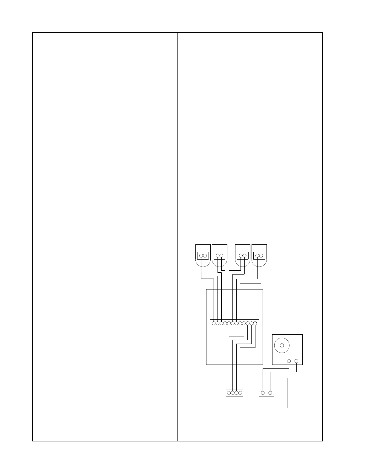
Figure 1. Test Setup Diagram ......................................................................................................... 4
Figure 2. Crossover Top Side and Etch Layout............................................................................... 5
Figure 3. FreeSpace
Figure 4. FreeSpace Model 1B Acoustimass Module Assembly Diagram ...................................... 6
Part List..........................................................................................................................................7-8
FreeSpace Model 1B Acoustimass Module (Per Figure 4)........................................................... 7
Figure 5. FreeSpace Model 1B Acoustimass Bass Module Rear Panel Label ............................... 7
FreeSpace Model 1B Acoustimass Module Crossover Assembly (Per Figure 6) ...................... 8
Figure 6. FreeSpace Model 1B Acoustimass Module Crossover Assembly ................................... 8
Packing List ...................................................................................................................................... 9
FreeSpace Model 1B Acoustimass Module (Per Figure 7)........................................................... 9
Figure 7. FreeSpace Model 1B Acoustimass Module Packing Diagram .......................................... 9
®
Model 1B Acoustimass® Module Schematic Diagram.................................. 5
SPECIFICATIONS
External Dimensions: Bass Module: 19" x 14" x 7.5"
Packed System: 26.2" x 19.8" x 10.6"
Weight: Bass Module: 18.7 lb
Transducer Complement: 2 - 5 1/4" Woofers
Power Handling: 100 Watts per channel
Usable Frequency Range: Bass Box: 55 Hz to 200 Hz
Sensitivity: Pink Noise: 76dB-spl, 1 Watt @ 1 Meter
IEC Noise: 78.6dB-spl, 1 Watt @ 1 Meter
PROPRIETARY INFORMATION
THIS DOCUMENT CONTAINS PROPRIETARY INFORMATION OF
BOSE
®
CORPORATION WHICH IS BEING FURNISHED ONLY
FOR THE PURPOSE OF SERVICING THE IDENTIFIED BOSE
PRODUCT BY AN AUTHORIZED BOSE SERVICE CENTER OR
OWNER OF THE BOSE PRODUCT, AND SHALL NOT BE
REPRODUCED OR USED FOR ANY OTHER PURPOSE.
1
Page 2

PRODUCT DESCRIPTION
The FreeSpace® Model 1B Acoustimass® Module is a passive bass unit with a crossover at
200 Hz. The crossover will feed four (two per channel) 8Ω impedance, or eight
(four per channel) 4Ω impedance FreeSpace Model 6 loudspeakers. It offers several
advantages over a powered bass box system.
• The FreeSpace Model 1B Acoustimass Module does not require the wiring of AC mains
during installation. This can represent a significant savings in installation costs.
• The FreeSpace Model 1B Acoustimass Module is designed to be used with the AMPlus™
Series Amplifiers. It is able to take advantage of all of the features of the amplifiers, such
as Opti-voice
selection.
• The FreeSpace Model 1B Acoustimass Module can also be used with the the Model 8,
Model 32, and Model 25 loudspeakers to form a complete extended bandwidth system.
®
paging, Dynamic EQ, Page Vectoring, Dynamic Compensation, and source
2
Page 3

DISASSEMBLY/ASSEMBLY PROCEDURES
Note: Refer to Figure 4. for the following
procedures.
1. Driver Removal
1.1 Remove the six screws (5) that secure
the rear cover (8) to the cabinet.
1.2 Slide the rear cover off far enough to
reach the woofer harness cables (10) on
the crossover assembly (9).
1.3 Unplug the woofer harness cables from
the crossover assembly. You can now
completely remove the rear cover.
1.4 Remove the four screws (3) that secure
the woofer assembly (2) to the cabinet.
1.5 Cut the wires as close to the terminals
as possible.
2. Driver Replacement
®
Note: Refer to Figure 3, FreeSpace
1B Acoustimass
®
Module Schematic
Model
Diagram, for wiring information.
3. Crossover Removal
3.1 Remove the six screws (5) that secure
the rear cover (8) onto the Acoustimass
Bass Module.
3.2 Slide the rear cover off of the bass box
until you can reach the connectors for the
woofer harness cables (10).
3.3 Unplug the woofer harness
cables from the crossover assembly (9).
3.4 Unplug the connector harness
assembly (7) from the crossover assembly.
3.5 Remove the four screws that secure
the crossover assembly to the rear panel.
4. Crossover Replacement
4.1 Mount the crossover assembly (9) to the
rear cover (8) using the four screws
removed in Procedure 3.5.
4.2 Plug the connector harness
assembly (7) onto the crossover assembly.
2.1 Observing polarity, solder the woofer
harness cable (10) leads to the woofer
assembly (2).
2.2 Secure the woofer assembly to the
cabinet using the four screws (3) removed in
Procedure 1.4.
Note: Be sure to re-align the woofer
gasket (1) with the cabinet in order to make
an airtight seal.
2.3 Plug the connectors for the woofer
harness cables onto the crossover
assembly (9) located on the rear cover (8).
2.4 Slide the rear cover back onto the
bass box, and secure it using the six screws
(5) removed in Procedure 1.1.
4.3 Plug the woofer harness cables (10)
onto the crossover assembly.
4.4 Secure the rear cover to the
Acoustimass Bass Module using the six
screws (5) removed in Procedure 3.1.
3
Page 4
TEST PROCEDURES
1. Rub and Tick Test
1.1 Perform Disassembly/Assembly
Procedure 1.1-1.4 in order to gain access to
the driver to be tested.
1.2 Apply a 10 Volt rms, 10 Hz signal to
the driver input terminals.
1.3 Replace any driver that has a rubbing
or ticking noise. Quiet ticks are acceptable
if they cannot be heard at a distance of 1
foot.
Note: To distinguish between normal
suspension noise and rubs or ticks, displace
the surround of the driver slightly with your
fingers. If the noise can be made to go
away, or get worse, it is a tick or a rub, and
the driver should be replaced. If the noise
stays the same, it is suspension noise and
the driver is fine. Suspension noises will not
be heard with program material.
3.3 Sweep the oscillator from 10 Hz to
500 Hz. Sweep rate shall be 3-5 seconds.
Listen carefully for buzzes, rattles, or other
noises.
Note: A whooshing noise from the bass
box ports at approximately 45 Hz and 110
Hz is acceptable (port tuned frequencies).
Note: A small air leak at the input/output
terminal is acceptable.
3.4 Reduce input signal to 4 Vrms, 500 Hz.
3.5 Sweep the oscillator from 500 Hz to
7 kHz. Sweep rate shall be 3-5 seconds.
Listen carefully for buzzes, rattles, or other
noises.
3.6 Repeat sweep test for LEFT channel
only, then for RIGHT channel only.
3.7 Listen for any extraneous noises.
2. Air Leak Test
2.1 Perform test setup in Figure 1. Test
Setup Diagram, but do not connect the
satellite speakers.
2.2 Apply a 14 Vrms, 45 Hz signal to the
bass module.
2.3 Listen carefully for air leaks (audible as
a whistling or sputtering sound) at cabinet
seams. Minimum listening time should be 5
seconds/test.
3. System Sweep Test
3.1 Connect the system as in Figure 1.
Test Setup Diagram.
Note: Refer to Figure 5. for the
Acoustimass
®
Bass Module Rear Panel
Label diagram.
+
+
-
-
+-
-
+
+
-+-
++
-
-
+
-
+
+-
-
+
-
+
InputOutputs
Satellites
Bass Module
Audio Signal
Generator
-
+
-
3.2 Apply a 14 Vrms, 10 Hz signal to both
the left and right inputs.
Power Amplifier
Figure 1. Test Setup Diagram
4
Page 5

RED
INPUT FROM
AMPLIFIER
LEFT (RIGHT)
+
Figure 2. Crossover Top Side and Etch Layout
RED
C1
+
WOOFER
-
SATELLITES
BLACK
-
Figure 3. FreeSpace® Model 1B Acoustimass® Module Schematic Diagram
(one channel shown)
5
BLACK
Page 6

Front View
12
12
11
(2x)
2
(2x)
3
(8x)
1
(2x)
Top View
4
(6x)
5
(6x)
6
(2x)
7
Figure 4. FreeSpace
9
10
(2x)
Exploded View
®
Model 1B Acoustimass® Module Assembly Diagram
8
6
Page 7

PART LIST
FreeSpace® Model 1B Acoustimass® Module (Per Figure 4)
Item
Number
1 Gasket, Woofer, 6.5" 104794-08 2
2 Woofer Assy., 5.25 ", AM-5 P III 172276 2
3 Screw, Tapp, 8 - 11x .75, PAN,
XRC/SQ
4 Grommet, Grille, .635" 117995 6
5 Screw, Tapp, 8 - 11x 1.5, PAN,
XRC/SQ
6 Screw, Tapp, 8 - 11x 1.00, PAN,
XRC/SQ
7 Connector Harness Assembly 187462 1
8 Cover, Rear, Pro Grey 184885-8 1
8 Cover, Rear, White 184885-9 1
9 Crossover Assy. Model 1B 187894 1
10 Harness, Woofer 172275 2
11 Screw, 1/4 x 20, 3/4 L, Hex, BH 179114-12 4
12 Bracket, Bassbox 184892 1
Description Part Number Qty. per
172672-12 8
172672-24 6
172672-16 2
Assy.
Figure 5. FreeSpace Model 1B Acoustimass Bass Module Rear Panel Label
7
Page 8

PART LIST
FreeSpace® Model 1B Acoustimass® Module Crossover Assembly (Per Figure 6)
Reference
Designator
C1, C2 1 Cap, El, BP, 85, 50V, 20%, 100uF 142065 2
J2, J3 2 Connector, Header, Inline, 2 Position 13 3220-02 2
J1 3 Conn, Header, 12 Pin, .200, Vert 187902-12 1
- 4 Crossover PCB Assy, Bare Board 187495 1
- 5 Screw, Tapp, 8-11x.625, PAN,XRC/S 172672-10 4
- 6 Foot, .25x.50, Black 174402-1 4
(4x)
Item
Number
5
Description Part
Number
2
(2x)
4
Qty. per
Assy.
(2x)
1
3
6
(4x)
Figure 6. FreeSpace Model 1B Acoustimass Module Crossover Assembly
8
Page 9

PACKING LIST
FreeSpace® Model 1B Acoustimass® Module (Per Figure 7)
Item
Description Part Number Qty. per
Number
1 Packing, Corner Post, Bass Mod. 148044 2
2 Packing, Corner Post, Bass Insert 148364 2
3 Bag, Poly, 13.5 x 35 x 9.5 x 1 Mil 114522 1
4 Packing, Crease Sheet, S/W 190555-001 1
5 Bracket, Wallmount 184891 1
6 Bag, Poly, 14.38 x 9 .87 x 2 Mil 103351 1
7 Card, Registration 180089 1
8 Clip, Wire 187523 1
9 Sheet, Installation, FS Model 1B 187905 1
10 Packing, Crease Sheet, D/C, D/W 190554-001 1
11 Packing Tube, Joined 186732 1
12 Cover Assy, AM10, Pro Grey 187096-3 1
12 Cover Assy, AM10, Arctic White 187096-4 1
13 Carton, RSC 184 888-001 1
2
Assy.
12
1
3
10
11
6
7 8 9
5
4
13
11
Figure 7. FreeSpace Model 1B Acoustimass Module Packing Diagram
9
Page 10

FREESPACE® MODEL 1B
®
®
ACOUSTIMASS
®
MODULE
©
1997 Bose Corporation
Service Manual
Part Number 191983 REV 00
Page 11

SPECIFICATIONS AND FEATURES SUBJECT TO CHANGE WITHOUT NOTICE
®
®
Bose Corporation
The Mountain
Framingham Massachusetts USA 01701
P/N 191983 REV. 00 08/97 FOR TECH. ASSISTANCE OR PART ORDERS, CALL 1-800-367-4008
 Loading...