

Page 1

AmPlusTM 50 and 100 Amplifiers
TDA7294 output devices failing
194101-B2
7/2000
Symptom: No output
Reason: The TDA7294 amplifier ICs are being subjected to destructive reverse-biasing when
connected to highly inductive loads.
Solution: In units built with a Rev. 04 or lower PCB, install two General Semiconductor SB160
or Motorola MBR160 Schotty barrier rectifier diodes in the locations listed in the rework
procedure below to protect the output devices against destructive reverse-biasing.
Rework Procedure:
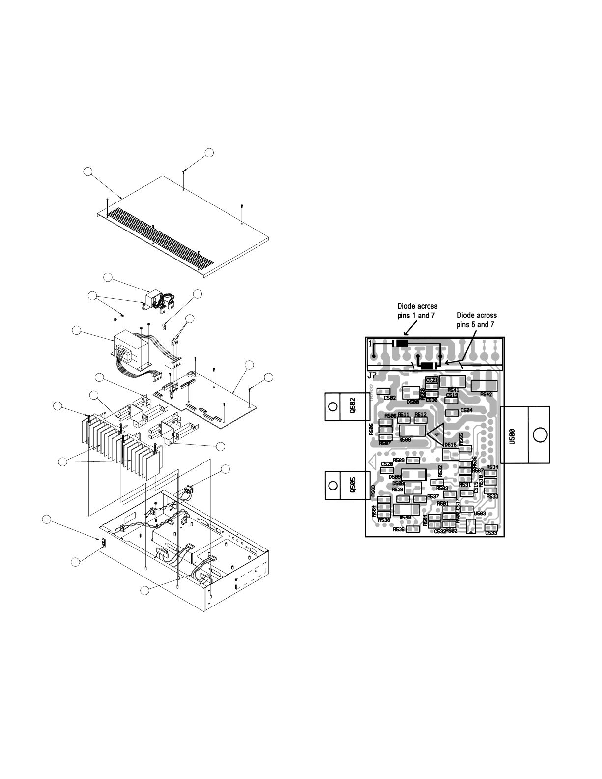
Note: Refer to Figures 1 and 2 on the back of this sheet for the following steps. The AmPlus 100 amplifier is
shown in Figure 1. The AmPlus 50 is the same layout, but with only one channel and one amplifier
module used.
1. Remove the five screws (1) that secure the amplifier’s top cover (2) to the chassis (16).
2. Unplug the amplifier module cables from the main PCB (8) at J7B and/or J8B.
3. Remove the screws (12) that secure the amplifier module(s) to the chassis.
4. On each amplifier module, remove the clips (10) that secure the amplifier module PCB to the heatsink (14).
Take care not to damage them.
5. On the SMD side of the amplifier PCB, attach an SB160 diode across pins 1 and 7 of connector J7/J8.
The cathode (banded) lead of the diode attaches to pin 1. Insulate the exposed leads with nylon tubing
to prevent shorts. See Figure 2.
6. Attach another SB160 diode across pins 5 and 7 of connector J7/J8. The cathode (banded) lead attaches
to pin 7. Insulate the exposed leads with nylon tubing to prevent shorts. See Figure 2.
7. Secure the amplifier PCB to the heatsink (14) using the clips (10) removed in step 4.
Make sure that the sil-pads (11 and 13), fastened to the back of U500, Q502 and Q505 (or U501, Q508
and Q511) are still intact and that the metal casings of these devices are not shorted to the heatsink.
8. Install the amplifier module(s) into the amplifier chassis (16) using the screws (12) removed in step 3.
9. Connect the amplifier module cables to the main PCB (8) at J7B and/or J8B.
10. Replace the top cover (2) and secure it in place using the screws (1) removed in step 1.
11. In the AmPlus 50 and 100 service manual, part number 194101, perform test 6 for the AmPlus 100
amplifier and test 5 for the AmPlus 50 amplifier to verify that the amplifier operates properly after rework.
Units built with a Rev. 04 or lower PCB
FRACAS: D291
Page 2
5 PLACES
1
2
3
4 PLACES
7 PLACES
5
4
6
7
8
9
6 PLACES
11
10
(4) PLACES
12
(2) PLACES
13
14
15
16
17
2 PLACES
18
Figure 1. AmPlusTM 100 Amplifier Exploded View
Figure 2. AmPlus Amplifier PCB
Diode Location Diagram
 Loading...