


Bose® Virtually Invisible® 191 Speakers
Bose
®
Virtually Invisible
®
191 Speakers
Owner’s installation guide
Bedienungs- und Installateuranleitung
Guía de instalación
Guide d’installation
Installatiehandleidung

Safety Information
Important words of caution
English
WARNING:
Installation shall be in accordance with the applicable section of the National
Electrical Code, ANSI/NFPA 70, and/or the National Fire Alarm Code, ANSI/NFPA 72, as
applicable. The wiring method and compartment shall be such as not to interfere with the
operation of the speaker.
CAUTION:
CAUTION:
Consult local building codes before you get started with this installation.
This product is not intended for use in Air-Handling Plenum Spaces.
Please read this owner’s guide completely before you start. Then carefully consider your
experience with using the tools and taking the precautions referred to here.
CAUTION:
Failure to follow the instructions in this owner’s guide voids all warranties on your
speakers.
If you have doubts about doing this installation, you should contact either the dealer you
purchased the product from, an electrician, or a professional audio/video installer. You can
describe the job and request a cost estimate before committing to installation service.
Small check marks call your attention to the tools you’ll need for the next step.
Tips
offer ideas to make the job go easier and help you avoid mistakes.
Use these instructions with wood frame or similar construction only
1
Each speaker requires 8
cm) of vertical space inside the wall or ceiling, plus a minimum of 4
of depth from the face of wallboard that is a maximum of 1 inch (2.5 cm) thick.
Bose recommends installing these speakers only in wood frame or similar construction
where there is enough space between studs, as is found in 2 x 4 or 2 x 6 wall/ceiling
construction. The instructions in this guide are specific to that type of installation only.
Note:
These speakers are not designed for installation in walls or ceilings of masonry.
/
inches (20.5 cm) of horizontal space, and 14 inches (35.6
16
1
/
inches (10.5 cm)
8
2

Where to find...
Introduction . . . . . . . . . . . . . . . . . . . . . . . . . . . . . . . . . . . . . . . . . . . . . . . . . . . . . . . . . . . . . . . . . . . 4
Preparation . . . . . . . . . . . . . . . . . . . . . . . . . . . . . . . . . . . . . . . . . . . . . . . . . . . . . . . . . . . . . . . . . . . 5
Steps to Installing . . . . . . . . . . . . . . . . . . . . . . . . . . . . . . . . . . . . . . . . . . . . . . . . . . . . . . . . . . . . . . 15
Reference . . . . . . . . . . . . . . . . . . . . . . . . . . . . . . . . . . . . . . . . . . . . . . . . . . . . . . . . . . . . . . . . . . . . . 32
Contents
Before you begin... . . . . . . . . . . . . . . . . . . . . . . . . . . . . . . . . . . . . . . . . . . . . . . . . . . . . . . . . . . 4
What makes this speaker better also makes it different . . . . . . . . . . . . . . . . . . . . . . . . . . . 4
Unpacking . . . . . . . . . . . . . . . . . . . . . . . . . . . . . . . . . . . . . . . . . . . . . . . . . . . . . . . . . . . . . . . . . 5
Other equipment you’ll need . . . . . . . . . . . . . . . . . . . . . . . . . . . . . . . . . . . . . . . . . . . . . . . 5
Consider which shape you prefer for your speakers . . . . . . . . . . . . . . . . . . . . . . . . . . . . . 6
Considering your wall type and the approach it requires . . . . . . . . . . . . . . . . . . . . . . . . . . . . . 6
Accessories that can help . . . . . . . . . . . . . . . . . . . . . . . . . . . . . . . . . . . . . . . . . . . . . . . . . . 7
Use special care in cutting through plaster and lath . . . . . . . . . . . . . . . . . . . . . . . . . . . . . 7
Installing in a pre-wired room . . . . . . . . . . . . . . . . . . . . . . . . . . . . . . . . . . . . . . . . . . . . . . . 7
Installing in an exterior wall . . . . . . . . . . . . . . . . . . . . . . . . . . . . . . . . . . . . . . . . . . . . . . . . . 8
Deciding on speaker placement . . . . . . . . . . . . . . . . . . . . . . . . . . . . . . . . . . . . . . . . . . . . . . . . 8
Select the general wall area for one speaker . . . . . . . . . . . . . . . . . . . . . . . . . . . . . . . . . . . 9
Using speaker cord . . . . . . . . . . . . . . . . . . . . . . . . . . . . . . . . . . . . . . . . . . . . . . . . . . . . . . . . . . 11
Prepare the cord . . . . . . . . . . . . . . . . . . . . . . . . . . . . . . . . . . . . . . . . . . . . . . . . . . . . . . . . . 11
Planning to run speaker cord . . . . . . . . . . . . . . . . . . . . . . . . . . . . . . . . . . . . . . . . . . . . . . . . . . 11
Before the wallboard goes up . . . . . . . . . . . . . . . . . . . . . . . . . . . . . . . . . . . . . . . . . . . . . . . 13
Where the walls are finished . . . . . . . . . . . . . . . . . . . . . . . . . . . . . . . . . . . . . . . . . . . . . . . . 13
Before you make any holes . . . . . . . . . . . . . . . . . . . . . . . . . . . . . . . . . . . . . . . . . . . . . . . . . . . . 15
Drill a pilot hole for testing the wall space . . . . . . . . . . . . . . . . . . . . . . . . . . . . . . . . . . . . . . . . . 15
Using the template for this first step . . . . . . . . . . . . . . . . . . . . . . . . . . . . . . . . . . . . . . . . . . 15
Drilling the pilot hole . . . . . . . . . . . . . . . . . . . . . . . . . . . . . . . . . . . . . . . . . . . . . . . . . . . . . . 17
Testing the space behind the hole . . . . . . . . . . . . . . . . . . . . . . . . . . . . . . . . . . . . . . . . . . . 18
Repairing a pilot hole . . . . . . . . . . . . . . . . . . . . . . . . . . . . . . . . . . . . . . . . . . . . . . . . . . . . . 20
Passing the pilot hole test . . . . . . . . . . . . . . . . . . . . . . . . . . . . . . . . . . . . . . . . . . . . . . . . . . 20
Prepare the wall for inserting the speaker . . . . . . . . . . . . . . . . . . . . . . . . . . . . . . . . . . . . . . . . . 21
Using the template a second time . . . . . . . . . . . . . . . . . . . . . . . . . . . . . . . . . . . . . . . . . . . 21
Cutting the speaker hole . . . . . . . . . . . . . . . . . . . . . . . . . . . . . . . . . . . . . . . . . . . . . . . . . . . 22
Insert and wire the speaker . . . . . . . . . . . . . . . . . . . . . . . . . . . . . . . . . . . . . . . . . . . . . . . . . . . . 23
Insert the speaker into the opening . . . . . . . . . . . . . . . . . . . . . . . . . . . . . . . . . . . . . . . . . . 24
Make the speaker connections . . . . . . . . . . . . . . . . . . . . . . . . . . . . . . . . . . . . . . . . . . . . . . 26
Test the speaker now . . . . . . . . . . . . . . . . . . . . . . . . . . . . . . . . . . . . . . . . . . . . . . . . . . . . . 26
Secure the speaker to the wall . . . . . . . . . . . . . . . . . . . . . . . . . . . . . . . . . . . . . . . . . . . . . . . . . 28
If the speaker looks crooked . . . . . . . . . . . . . . . . . . . . . . . . . . . . . . . . . . . . . . . . . . . . . . . 29
When the grille is finally in place . . . . . . . . . . . . . . . . . . . . . . . . . . . . . . . . . . . . . . . . . . . . . 29
Choosing to paint the speakers . . . . . . . . . . . . . . . . . . . . . . . . . . . . . . . . . . . . . . . . . . . . . . . . 29
Painting the grille . . . . . . . . . . . . . . . . . . . . . . . . . . . . . . . . . . . . . . . . . . . . . . . . . . . . . . . . 30
Painting the frame . . . . . . . . . . . . . . . . . . . . . . . . . . . . . . . . . . . . . . . . . . . . . . . . . . . . . . . . 31
Troubleshooting . . . . . . . . . . . . . . . . . . . . . . . . . . . . . . . . . . . . . . . . . . . . . . . . . . . . . . . . . . . . 32
Customer service . . . . . . . . . . . . . . . . . . . . . . . . . . . . . . . . . . . . . . . . . . . . . . . . . . . . . . . . . . . 32
Warranty period . . . . . . . . . . . . . . . . . . . . . . . . . . . . . . . . . . . . . . . . . . . . . . . . . . . . . . . . . . . . . 32
Accessories . . . . . . . . . . . . . . . . . . . . . . . . . . . . . . . . . . . . . . . . . . . . . . . . . . . . . . . . . . . . . . . . 33
Technical information . . . . . . . . . . . . . . . . . . . . . . . . . . . . . . . . . . . . . . . . . . . . . . . . . . . . . . . . 33
English
Deutsch
Español
Français
Nederlands
For your records
Serial numbers are located on the center rear of each of the Virtually Invisible® 191 speakers.
Serial numbers:______________________________ and __________________________________
Dealer name:_______________________________________________________________________
Dealer phone:_____________________________Purchase date: __________________________
We suggest you keep your sales receipt and warranty card together with this owner’s guide.
3
Introduction
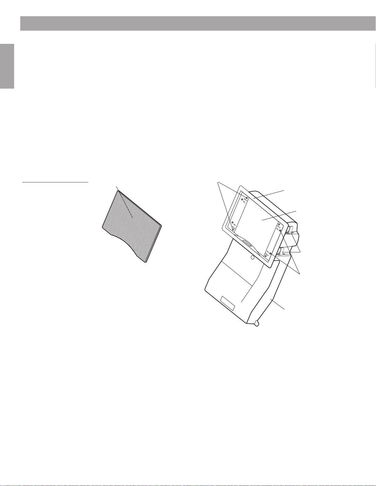
Rectangular speaker
frame
Speaker face
Speaker enclosure
Dogleg clamp
screws
Rectangular grille
Speaker frame screws
Dogleg clamps
Before you begin...
Please be sure to read this guide carefully before you do any cutting. There are many
factors to consider when choosing a location for your speakers.
English
Figure 1
Size and shape of the
speaker enclosure, as
shipped with the rectangular frame attached
Thank you for choosing to install Bose® Virtually Invisible® 191 speakers in your room.
Innovative engineering and advanced design enable these speakers to deliver Bose quality
performance for big impact in spite of their small size.
®
Virtually Invisible
191 speakers feature an Articulated Array® speaker configuration
that delivers the type of clear, lifelike sound and even coverage known as Bose Stereo
Everywhere® speaker performance.
What makes this speaker better also makes it different
When installed, Virtually Invisible® 191 speakers take up very little wall space. What isn’t
apparent is their advanced enclosure design, shown in Figure 1. It ensures predictably fine
performance wherever the speakers are installed, regardless of the size and shape of the wall
space. It also helps prevent the speaker sound from invading other rooms, a common problem with installed speakers of more conventional design.
4
Preparation
5
1
/
2
" (14 cm
)
8
1
/
1
6
" (20.5 cm
)
14
1
/
2
" (36.9 cm
)
TA
PE
HERE
TA
PE
HER
E
TAPE
HER
E
WHITE CUT OUT AREA
W
H
IT
E
C
U
T
O
U
T
A
R
EA
Pilot Hole
W
A
R
NING
: Make sure the spot chosen is safe for cutting. Do not cut through
surfaces that have hazards, such as electrical wiring, conduits or plumbing,
concealed behind them. If you are not sure, consult a professional installer
before you proceed.
DO NOT
CUT AROUND
GRAY AREA
English & Translations
W
A
R
N
I
N
G
:
Make sure the spot chosen is safe for cutting. Do not cut through surfaces that have hazards, such as electrical
wiring, conduits or plumbing, concealed behind them. If you are not sure, consult a professional installer before you proceed.
W
A
R
N
I
N
G
:
Make sure the spot chosen is safe for
drilling. Do not cut through surfaces that have hazards
concealed behind them, such as electrical wiring,
conduits or plumbing. If you are not sure, consult a
professional installer before you proceed.
W
A
R
N
I
N
G
:
Make sure the spot chosen is safe for
drilling. Do not cut through surfaces that have hazards
concealed behind them, such as electrical wiring,
conduits or plumbing. If you are not sure, consult a
professional installer before you proceed.
W
A
R
N
I
N
G
:
Make sure the
spot chosen is safe for
drilling. Do not cut through
surfaces that have hazards
concealed behind them,
such as electrical wiring,
conduits or plumbing. If you
are not sure, consult a
professional installer before
you proceed.
W
A
R
N
I
N
G
:
Make
sure the spot chosen
is safe for drilling. Do
not cut through
surfaces that have
hazards concealed
behind them, such
as electrical wiring,
conduits or
plumbing. If you are
not sure, consult a
professional installer
before you proceed.
W
A
R
N
I
N
G
:
Make sure the spot chosen is safe
for drilling. Do not cut through surfaces that have
hazards concealed behind them, such as
electrical wiring, conduits or plumbing. If you
are not sure, consult a professional installer
before you proceed.
W
A
R
N
I
N
G
:
Make sure the spot
chosen is safe for drilling. Do not cut
through surfaces that have hazards
concealed behind them, such as
electrical wiring, conduits or plumbing.
If you are not sure, consult a
professional installer before you
proceed.
9" (22.9 cm
)
TAP
E
H
ER
E
T
r
a
n
s
l
a
t
i
o
n
s
b
e
l
o
w
TAP
E
H
ER
E
TA
PE
H
ERE
DO NOT
CUT AROUND
GRAY AREA
DO NOT
CUT AROUND
GRAY AREA
DO NOT
CUT AROUND
GRAY AREA
DO NOT
CUT AROUND
GRAY AREA
DO NOT
CUT AROUND
GRAY AREA
DO NOT
CUT AROUND
GRAY AREA
DO NOT
CUT AROUND
GRAY AREA
T
A
P
E
H
E
R
E
WHITE CUT OUT AREA
WHITE CUT OUT AREA
P
ilot H
ole
W
A
R
N
I
N
G
:
Make sure the spot chosen is safe for cutting.
Do not cut through surfaces that have hazards, such as
electrical wiring, conduits or plumbing, concealed behind
them. If you are not sure, consult a professional installer
before you proceed.
DO NOT
CUT AROUND
GRAY AREA
W
A
R
N
IN
G
: Make sure the spot chosen is safe for cutting. Do not cut through surfaces that have hazards, such as electrical
wiring, conduits or plumbing, concealed behind them. If you are not sure, consult a professional installer before you proceed.
W
A
R
N
IN
G
:
Make sure the spot chosen is safe for
drilling. Do not cut through surfaces that have hazards
concealed behind them, such as electrical wiring,
conduits or plumbing. If you are not sure, consult a
professional installer before you proceed.
W
A
R
N
IN
G
: Make sure the spot chosen is safe for
drilling. Do not cut through surfaces that have hazards
concealed behind them, such as electrical wiring,
conduits or plumbing. If you are not sure, consult a
professional installer before you proceed.
W
A
R
N
IN
G
: Make
sure the spot chosen
is safe for drilling. Do
not cut through
surfaces that have
hazards concealed
behind them, such
as electrical wiring,
conduits or
plumbing. If you are
not sure, consult a
professional installer
before you proceed.
W
A
R
N
IN
G
:
Make sure the spot
chosen is safe for drilling. Do not cut
through surfaces that have hazards
concealed behind them, such as
electrical wiring, conduits or plumbing.
If you are not sure, consult a
professional installer before you
proceed.
T
A
P
E
H
E
R
E
T
ran
slatio
n
s b
elo
w
T
A
P
E
H
E
R
E
English & English & TTranslationsranslations
T
A
P
E
H
E
R
E
W
A
R
N
IN
G
: Make
sure the spot chosen
is safe for drilling. Do
not cut through
surfaces that have
hazards concealed
behind them, such
as electrical wiring,
conduits or
plumbing. If you are
not sure, consult a
professional installer
before you proceed.
W
A
R
N
IN
G
:
Make
sure the spot chosen
is safe for drilling. Do
not cut through
surfaces that have
hazards concealed
behind them, such
as electrical wiring,
conduits or
plumbing. If you are
not sure, consult a
professional installer
before you proceed.
W
A
R
N
IN
G
: Make sure the spot
chosen is safe for drilling. Do not cut
through surfaces that have hazards
concealed behind them, such as
electrical wiring, conduits or plumbing.
If you are not sure, consult a
professional installer before you
proceed.
TAPE
HERE
TAPE
HERE
DO NOT
CUT AROUND
GRAY AREA
DO NOT
CUT AROUND
GRAY AREA
DO NOT
CUT AROUND
GRAY AREA
DO NOT
CUT AROUND
GRAY AREA
DO NOT
CUT AROUND
GRAY AREA
DO NOT
CUT AROUND
GRAY AREA
DO NOT
CUT AROUND
GRAY AREA
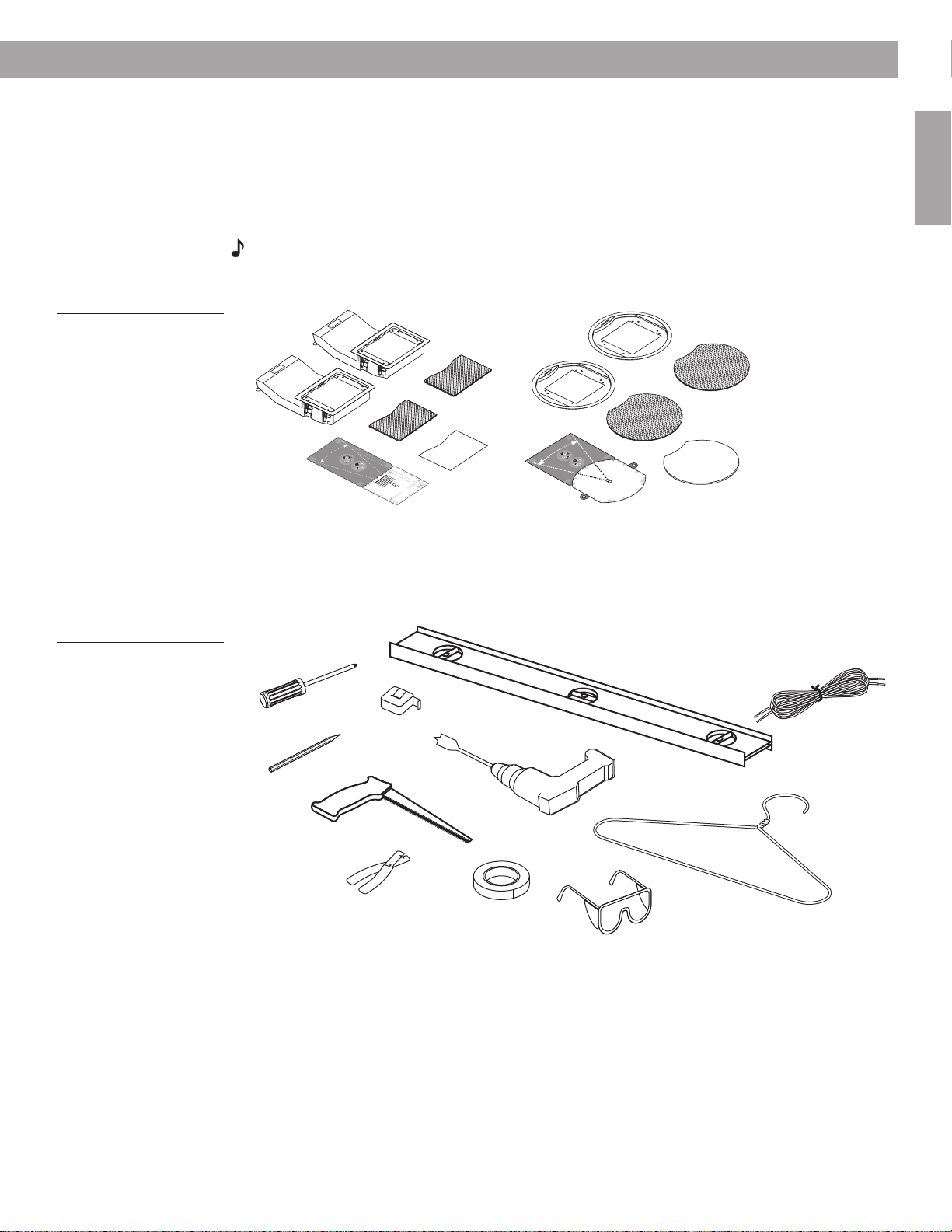
Speakers
Rectangular
speaker grilles
Rectangular
template
Round speaker grilles
Round speaker frames
Round
template
Rectangular
paint shield
Round paint shield
Speaker cord**
Sturdy wire
(such as a coat hanger)
that is 22 inches long
Half-inch spade bit
Carpenter’s level*
Phillips-head
screwdriver
Sharp pencil
Keyhole saw****
Protective eyewear
Painter’s tape***
Wire cutter/stripper
Tape measure
*Carpenter’s level is suggested for use when installing speakers in a wall.
**Speaker cord specifications are provided in “Using speaker cord,” beginning on page 11.
***Painter’s tape or other tape with light adhesive that will not damage paint or wallpaper.
****Cutting tool – For drywall: a keyhole saw, drywall saw, rotary cutting tool, or jigsaw
For plaster and lath: a saber saw or a rotary cuttin
g tool
Power drill
Unpacking
Figure 2
Contents of the carton:
• 2 Speakers, rectangular
frames attached
• 2 Rectangular speaker
grilles
• 1 Rectangular paint shield
• 1 Rectangular template
• 2 Round speaker frames
• 2 Round speaker grilles
• 1 Round paint shield
• 1 Round template
Carefully unpack the speakers. Save all packing materials, which provide the safest means to
transport your speakers as needed. If any part of the speaker pair appears damaged, do not
use the pair. Notify Bose or your authorized Bose® dealer immediately. For Bose contact information, refer to the address list included in the carton.
Check to be sure the carton includes all the parts shown in Figure 2.
Note:
Now is a good time to find the serial numbers on the back of each speaker. Copy those
numbers onto your warranty card and in the “For your records” space on page 3.
Other equipment you’ll need
Hardware for securing the speaker to a wall or ceiling comes attached to the speaker. But you
will need a variety of other equipment, including tools, to prepare the surface for installing the
speakers (Figure 3).
English
Figure 3
Items required to install the
speakers as instructed
5
Preparation
English
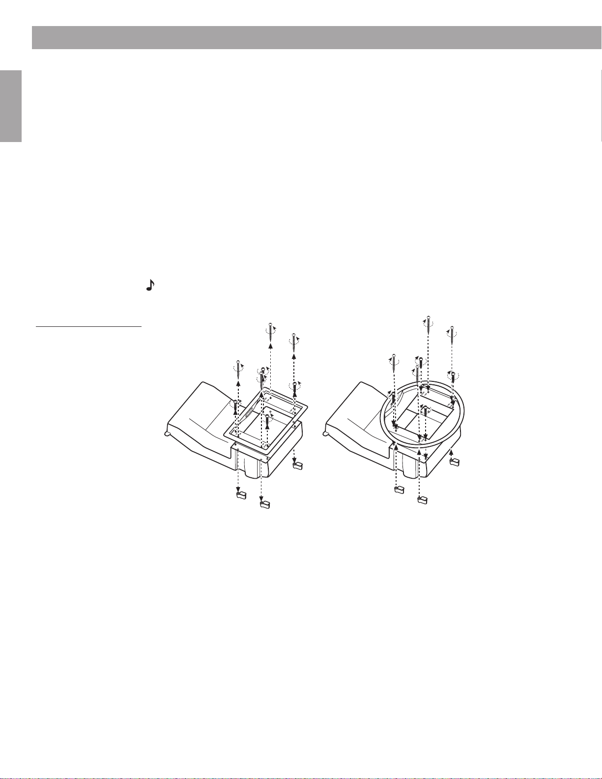
Figure 4
Replacing the rectangular
speaker frame with the
round frame
Wear clothing appropriate for the job, and consider using a drop cloth or other material to
protect the area from debris. How and where you install the speakers will determine your
need for optional equipment.
Optional items:
•A wire snake for running speaker cord behind wallboard
•A sturdy stool or ladder for installing speakers above your head
• Gloves and protection for your mouth, nose, and eyes for working with insulation
Consider which shape you prefer for your speakers
The design of your new Virtually Invisible® 191 speakers makes them well-suited to either wall
or ceiling installation. You also have a choice of a rectangular or round speaker face – the part
that is visible when the speaker is installed. Consider which shape will work best in the location you choose for the speakers.
If you prefer the round shape, it is easy to remove the rectangular frames and replace them
with the round frames provided in the carton. You can do it now or wait until you know for
sure where each speaker will fit. However, be sure to make that change before you insert
either speaker into the wall or ceiling.
Note:
The lip of the speaker frame prevents the speaker from slipping behind the wall and
out of reach. Do not remove the frame while the speaker is in the wall.
If you choose the round frames, use the round template provided in the carton. A round paint
shield is also supplied, in case you decide to paint the speaker.
Considering your wall type and the approach it requires
For working in a pre-wired room of finished construction with 2 x 4 stud walls covered with
wallboard, refer to “Steps to Installing,” beginning on page 15. These instructions cover
installation of the speakers, with either a rectangular or round grille, in a wall or ceiling.
If your installation is different, use the information below as it applies.
6

Preparation
Accessories that can help
For installation in a drop ceiling
optional Drop Ceiling Kit (Product Code #031355) for two speakers. It protects the tile from
bearing the weight of the speakers. Instructions are included with the kit.
For installation in new construction
two speakers. It is designed for use after the studs are in place and before the wallboard is
added to reserve a place for the speakers and indicate where the wallboard hole should be
made. It also protects the wallboard by providing additional support for the dogleg clamps
that secure the speaker to the wall. Instructions are included with the kit.
For more information or to order an accessory, contact your Bose
directly, refer to the address list included in the carton.
Use special care in cutting through plaster and lath
For wall construction of plaster and lath
• After you have drawn an outline of the hole to cut, tape around the outline and use a sharp
blade to make shallow cuts where the hole will be.
• Then, within the outline only, chip the plaster away until you expose the lath underneath.
• Finally, cut through the lath very carefully. Using an electric sabre saw can be quick but
risky. We recommend using a hand saw and proceeding cautiously to avoid damaging the
surrounding plaster.
(where tile is installed below the ceiling joists), Bose offers an
, Bose offers a Rough-in Kit (Product Code #031353) for
®
dealer. Or, to contact Bose
, use special care to prevent plaster from cracking:
English
Installing in a pre-wired room
An installation is simplest when the room has been pre-wired during construction. In that
case, the builder will have left speaker cord within easy reach of the intended speaker
positions.
How to determine pre-wiring
If you are not sure that you have a pre-wired room, or do not know where the wiring is
located, check the architectural drawings of your room or call the builder.
CAUTION:
drilling or cutting into the wall.
In the ideal situation, after cutting the speaker hole you can simply reach inside to locate the
length of cord the builder has installed.
What to do when the room is not pre-wired
In this case, you will need to run speaker cord from the receiver or amplifier through the wall
to the area you have chosen for installing the speakers.
If you have not done this before, be sure you understand the steps involved before you get
underway. Having a friend who can help with this step is advisable, too.
Information on running speaker cord in new construction is provided in “Before the wallboard
goes up,” beginning on page 13.
For running speaker cord inside finished walls, refer to “Where the walls are finished,” beginning on page 13.
It is important to know where the pre-wired cord is to prevent damaging it while
7

Preparation
English
Installing in an exterior wall
If you choose to install these speakers in an exterior wall (abutting the outside of your house),
you will undoubtedly encounter insulation behind the wallboard. This can complicate the
installation, requiring you to trim and push malleable insulation out of the way. You will need
to wear eye protection and gloves for working with fiberglass insulation.
WARNING:
cut into the wall.
Insulation will also impede your use of a pilot hole to test the size of the space behind the
wallboard. Doing such a test is recommended to make sure the space is large enough before
cutting a speaker-sized hole.
Special considerations in cold climate regions
With exterior wall installations in regions where outdoor temperatures dip below freezing for
days at a time, using a humidifier can cause condensation to form inside the speakers. This
can be more of a problem if the speakers are mounted upside down.
If you must mount in an exterior wall:
•Avoid installing the speakers upside down.
• Leave some of the insulation between the speakers and the exterior wall.
• Refrain from setting the humidifier on high, especially when outside temperatures are below
freezing.
If you believe the insulation inside a wall may be composed of asbestos,
Choose a different location for the speakers instead.
do not
Deciding on speaker placement
How and where you use the speakers will also affect your procedure for installing them. Consider the options below, then follow the instructions that apply to your choices:
• How you will use the speakers?
– for stereo sound at the front of a room or seating arrangement, or
– as home theater front speakers, or
– as surround sound speakers at the rear of your viewing area
•What surface you will install in?
– a wall or ceiling
– if a wall, will it be an interior (abutting another room) or exterior (abutting the outside
surface) wall
– in finished or new construction
– if finished, is it plaster and lath or wallboard construction
8
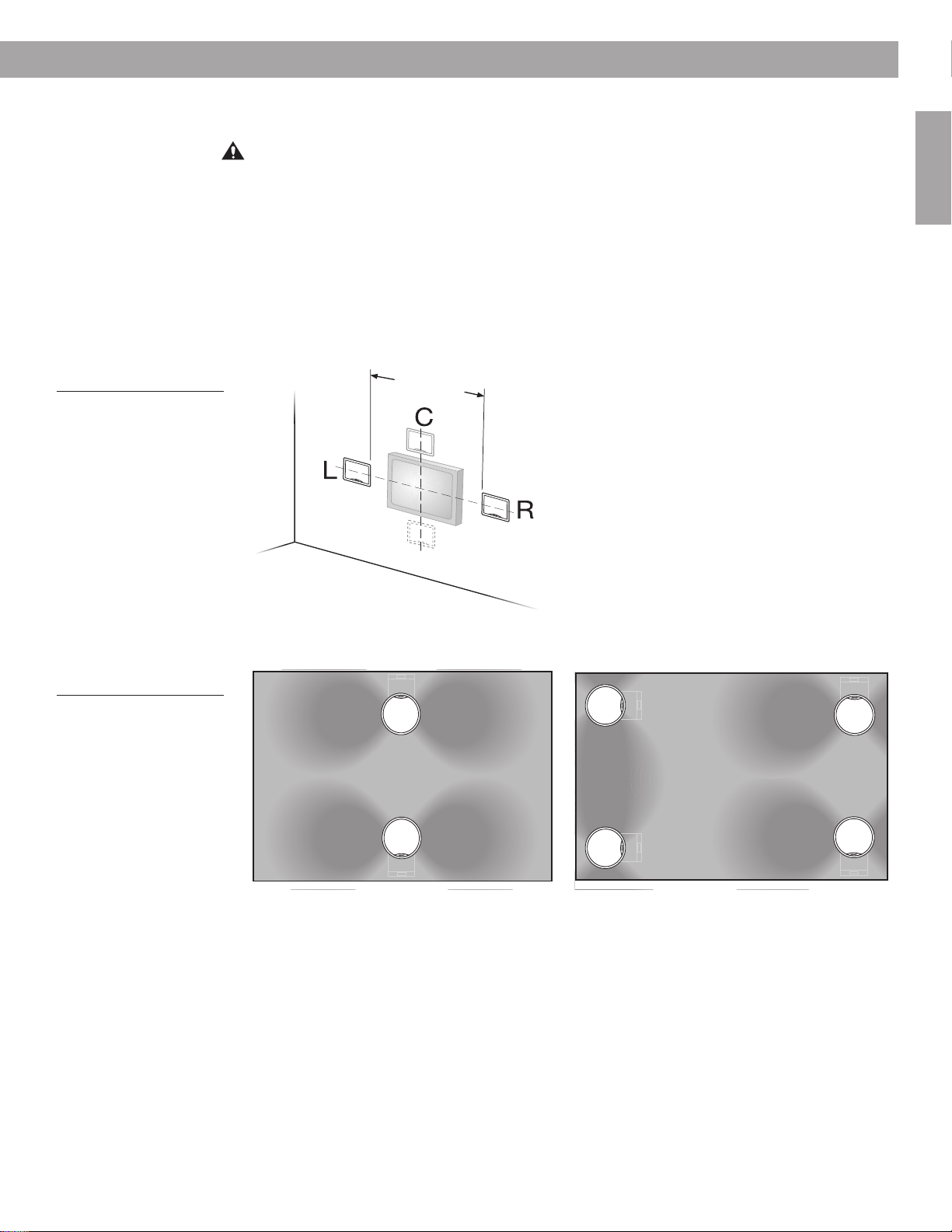
Figure 5
5´
(1.5m)
View of ceiling from below
Rear of room
Front of room
(b)
Orienting wall speakers for
front home theater use
Preparation
Select the general wall area for one speaker
As you decide where you want each speaker grille, use the guidelines below:
CAUTION:
other apparatus (including amplifiers) that produce heat.
• The two speakers should be a minimum of 5 feet (1.5 m) apart.
• For in-wall speakers providing stereo at the front of the room or home theater surround
sound from the rear, install them so each speaker grille is 4 to 6 feet (1.2 to 1.8 m) from the
floor for best performance.
• Neither speaker should be installed sideways in a wall; the enclosure should be either
above or below the speaker face.
• For in-wall home theater front speakers, install the pair horizontally aligned with the center
of the video screen (Figure 5).
Do not install near any heat sources, such as halogen lamps, registers, stoves, or
English
Figure 6
Orienting ceiling speakers
for the best coverage (a) for
stereo or (b) for home
theater front and surround
• For ceiling installation, pay attention to the direction of the speaker enclosure for best performance for stereo (Figure 6a) or for home theater (Figure 6b).
(a)
View of ceiling from below
• Height guidelines for in-wall speakers do not apply to ceiling installations.
9
Preparation
English & TT
ranslations
English & TT
ranslations
English
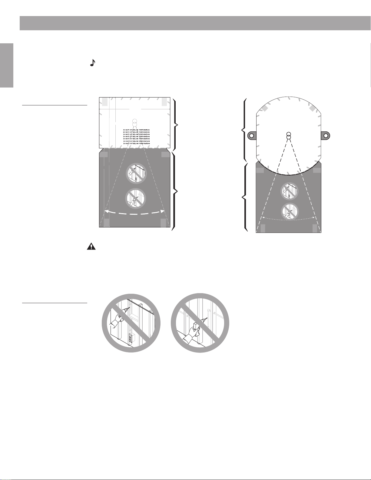
Figure 7
Template for either
rectangular-faced (left)
or round-faced (right)
speakers
• Each speaker enclosure extends
into the wall or ceiling
, as shown in the gray DO NOT CUT
area on the template (Figure 7), and below the grille. The speaker enclosure can be inserted
either up or down.
Note:
In cold climates where a humidifier is used, avoid inserting the speaker upside-down
in an exterior wall to prevent problems with condensation.
Allowing enough room both above and below the hole you draw provides a fallback in case
the area below your pilot hole is not suitable for the speaker enclosure.
TAPE
WARNING: Make sure the spot chosen is safe for cutting. Do not cut through
HERE
surfaces that have hazards, such as electrical wiring, conduits or plumbing,
concealed behind them. If you are not sure, consult a professional installer
before you proceed.
WARNING: Make sure the spot chosen is safe for cutting. Do not cut through surfaces that have hazards, such as electrical
wiring, conduits or plumbing, concealed behind them. If you are not sure, consult a professional installer before you proceed.
WARNING: Make sure the spot chosen is safe for
WHITE CUT OUT AREA
drilling. Do not cut through surfaces that have hazards
concealed behind them, such as electrical wiring,
conduits or plumbing. If you are not sure, consult a
professional installer before you proceed.
5 1/2" (14 cm)
WARNING: Make sure the
spot chosen is safe for
drilling. Do not cut through
surfaces that have hazards
concealed behind them,
such as electrical wiring,
conduits or plumbing. If you
are not sure, consult a
professional installer before
you proceed.
WARNING: Make sure the spot chosen is safe
for drilling. Do not cut through surfaces that have
hazards concealed behind them, such as
electrical wiring, conduits or plumbing. If you
are not sure, consult a professional installer
before you proceed.
TAPE
HERE
CUT AROUND
GRAY AREA
141/2" (36.9 cm)
9" (22.9 cm)
CUT AROUND
GRAY AREA
CUT AROUND
GRAY AREA
TAPE
CUT AROUND
HERE
GRAY AREA
DO NOT
DO NOT
DO NOT
DO NOT
8 1/16" (20.5 cm)
Translations below
WARNING: Make sure the spot chosen is safe for
drilling. Do not cut through surfaces that have hazards
concealed behind them, such as electrical wiring,
conduits or plumbing. If you are not sure, consult a
professional installer before you proceed.
Pilot Hole
English &
ranslations
WARNING: Make
sure the spot chosen
is safe for drilling. Do
not cut through
surfaces that have
hazards concealed
behind them, such
as electrical wiring,
conduits or
plumbing. If you are
not sure, consult a
professional installer
before you proceed.
WARNING: Make sure the spot
chosen is safe for drilling. Do not cut
through surfaces that have hazards
concealed behind them, such as
electrical wiring, conduits or plumbing.
If you are not sure, consult a
professional installer before you
proceed.
DO NOT
CUT AROUND
GRAY AREA
DO NOT
CUT AROUND
GRAY AREA
DO NOT
CUT AROUND
GRAY AREA
DO NOT
CUT AROUND
GRAY AREA
TAPE
HERE
WHITE CUT OUT AREA
TAPE
HERE
TAPE
HERE
FOR CUTTING
Large white area
represents what to cut
out for the speaker face.
On the template at right,
small circles outside the
white area indicate
additional holes needed
for the round-faced
speaker only.
NOT FOR CUTTING
Large gray area
represents space to
reserve behind the wall
for the speaker
enclosure.
On the template at right,
small gray tabs also
indicate where not to cut.
WARNING: Make sure the spot chosen is safe for cutting.
Do not cut through surfaces that have hazards, such as
TAPE
electrical wiring, conduits or plumbing, concealed behind
HERE
them. If you are not sure, consult a professional installer
before you proceed.
WARNING: Make sure the spot chosen is safe for
drilling. Do not cut through surfaces that have hazards
concealed behind them, such as electrical wiring,
conduits or plumbing. If you are not sure, consult a
professional installer before you proceed.
WARNING: Make
sure the spot chosen
is safe for drilling. Do
not cut through
surfaces that have
hazards concealed
behind them, such
as electrical wiring,
conduits or
plumbing. If you are
not sure, consult a
professional installer
before you proceed.
DO NOT
CUT AROUND
GRAY AREA
DO NOT
CUT AROUND
GRAY AREA
Translations below
WARNING: Make sure the spot chosen is safe for
drilling. Do not cut through surfaces that have hazards
concealed behind them, such as electrical wiring,
conduits or plumbing. If you are not sure, consult a
professional installer before you proceed.
Pilot Hole
English &
ranslations
CUT AROUND
GRAY AREA
CUT AROUND
GRAY AREA
WARNING: Make sure the spot chosen is safe for cutting. Do not cut through surfaces that have hazards, such as electrical
wiring, conduits or plumbing, concealed behind them. If you are not sure, consult a professional installer before you proceed.
WHITE CUT OUT AREA
WARNING: Make sure the spot
chosen is safe for drilling. Do not cut
through surfaces that have hazards
concealed behind them, such as
electrical wiring, conduits or plumbing.
If you are not sure, consult a
professional installer before you
proceed.
TAPE
HERE
DO NOT
CUT AROUND
GRAY AREA
DO NOT
CUT AROUND
GRAY AREA
TAPE
HERE
WARNING: Make
sure the spot chosen
is safe for drilling. Do
not cut through
surfaces that have
hazards concealed
behind them, such
as electrical wiring,
conduits or
plumbing. If you are
not sure, consult a
professional installer
before you proceed.
WARNING: Make sure the spot
chosen is safe for drilling. Do not cut
through surfaces that have hazards
concealed behind them, such as
electrical wiring, conduits or plumbing.
If you are not sure, consult a
professional installer before you
proceed.
DO NOT
DO NOT
TAPE
HERE
DO NOT
CUT AROUND
GRAY AREA
DO NOT
CUT AROUND
GRAY AREA
TAPE
HERE
WHITE CUT OUT AREA
TAPE
HERE
Figure 8
Cautions against unseen
danger, such as (a) electrical wires or (b) plumbing
pipes, behind the wallboard
CAUTION:
When installed, the speaker enclosure cannot be seen behind the wall or ceiling.
Do not attempt to nail, cut, or drill on that surface area. Puncturing the speaker enclosure with
a tool will seriously damage the speaker.
• All electrical wiring, vents, and plumbing pipes located inside the walls must be avoided
(Figure 8). Check with a trained professional if you need instructions on how to locate and
avoid them.
(a)
• Use of a stud finder can help ensure that the speaker hole is at least 4
(b)
3
/
" (12 cm) from a
4
stud or joist.
• The selected location should be at the height you want for both speakers and where you
can maintain the minimum distance of 5 feet (1.5 m) between them.
Keeping in mind the guidelines given:
1. Decide where the first speaker will go.
2. Select the location for the second speaker.
3. Use the provided template for drawing both a pilot hole and the speaker-face outline.
10
Using speaker cord
Before you cut any cord, estimate how much will be needed for each speaker.
To do so, measure the distance from the receiver/amplifier to where each speaker will be
installed. Make some allowance if the cord must go around corners or through walls, and
leave at least 14 inches (36 cm) of cord to pull from the wall for making the connections easily.
Note:
stand on the floor while making the connections.
Be sure to use the proper gauge (thickness) of speaker cord, determined by the length of
each piece.
Wire recommendations
Based on a maximum frequency response deviation of ±0.5 dB
CAUTION: Before running speaker cord through a wall or under a floor, check your local
building code requirements and safety regulations. If necessary, contact an A/V installer or
electrician for this information.
Preparation
If you are installing ceiling speakers, allowing extra cord will give you the freedom to
Gauge Maximum Length
2
18 AWG (0.82 mm
16 AWG (1.3 mm2)
14 AWG (2.1 mm
)
20 ft (6 m)
30 ft (9 m)
2
)
50 ft (15 m)
English
Prepare the cord
You will need a wire cutter and wire stripper for this work.
Speaker cord consists of two insulated wires. The insulation around one wire is marked
(striped, collared, or ribbed) to identify it as positive. The other wire is negative. It is important
to connect each wire to the proper terminal, positive to positive (+) and negative to
negative (–).
Note: It is sometimes difficult to distinguish wire markings. Inspect both wires carefully.
At the ends of each cord:
• Strip approximately
• Twist the bare end of each wire so loose strands will not touch across terminals.
Planning to run speaker cord
The techniques for running cord differ according to the condition of the walls you are working
with: new, unfinished construction or finished construction with the walls completed.
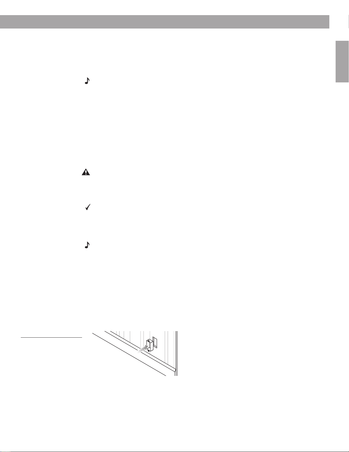
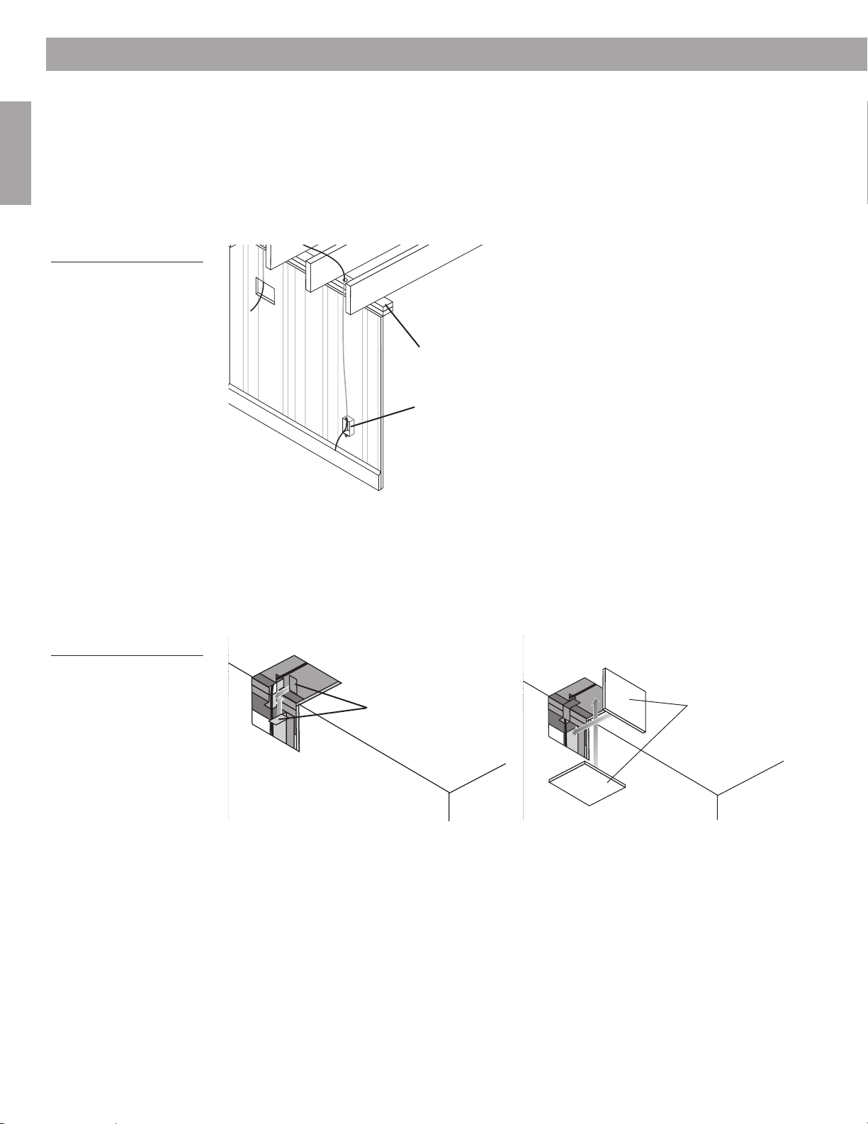
In either construction type, you need to mount an open-backed junction box in the wall near
the receiver or amplifier for cord coming out of the wall (Figure 9).
Figure 9
An open-backed junction
box that allows for cord
coming through the wall
near the receiver or
amplifier
1
⁄
inch (13 mm) of insulation from both wires.
2
11
Preparation
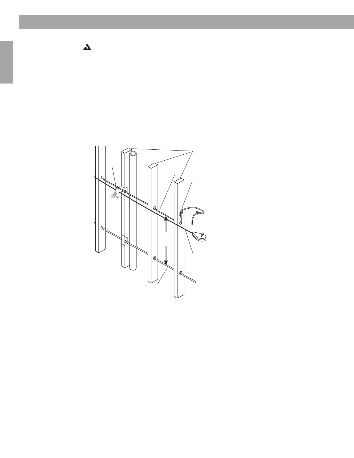
Speaker
cord
Nail
plate
Plumb line
for chalk
mark
Electrical
wire
Wire staple
3-4′
(1-1.3 m)
Studs
English
Figure 10
Techniques to use for running speaker cord through
studs or joists
You also need to observe safe and practical standards:
WARNING: Make sure the spot chosen is safe for drilling. Do not drill through surfaces that
may have hazards, such as electrical wiring, conduits, or plumbing concealed behind them.
Follow all other safety precautions.
• Consult local building codes to inform yourself of the requirements in your area.
• Use a drill bit large enough for the cord you will pull through the holes.
• Use an auger bit, if possible, to make the work of drilling multiple holes less tiring.
• Do not drill through a load-bearing beam. Consult the building contractor if this is an issue.
• Keep the cord 3 to 4 feet (1 to 1.3 m) away from electrical cord, which can create a hum or
buzz in the speakers (Figure 10).
•To avoid nails, drill holes in the center of each stud or joist.
• Use a nail plate to protect the cord if your only option is to notch a stud or joist.
12
• Line up holes as perfectly as possible to make pulling the cord through easier.
• Keep the cord taut enough so there are no sags.
• Do not pull the cord tight enough to create tension.
Preparation
Before the wallboard goes up
There are some standard guidelines for working in unfinished construction.
• Begin this work after the studs and joists are in and the electrical wiring is completed.
• Snap a chalk line across the face of the studs or the bottom of the joists and move back-
ward as you drill, so you can keep the last hole drilled in your line of sight.
• Never run speaker cord and electrical cable through the same hole or into the same junc-
tion box.
• If a short section of the cord must run parallel to nearby electrical cable, keeping that run to
the absolute minimum will result in less interference.
• Use metal conduit or shielded speaker cord if the cord must run next to electrical cable for
10 feet (3 m) or more.
• Use cable clamps or large wire staples to fasten the cord to a joist or stud wherever the
cord runs more than 4
• Use protective guardstrips, raceways, or conduits to protect the cord from being stepped
on or compressed in an attic or crawl space.
Where the walls are finished
Here are some suggestions for how to make this job easier.
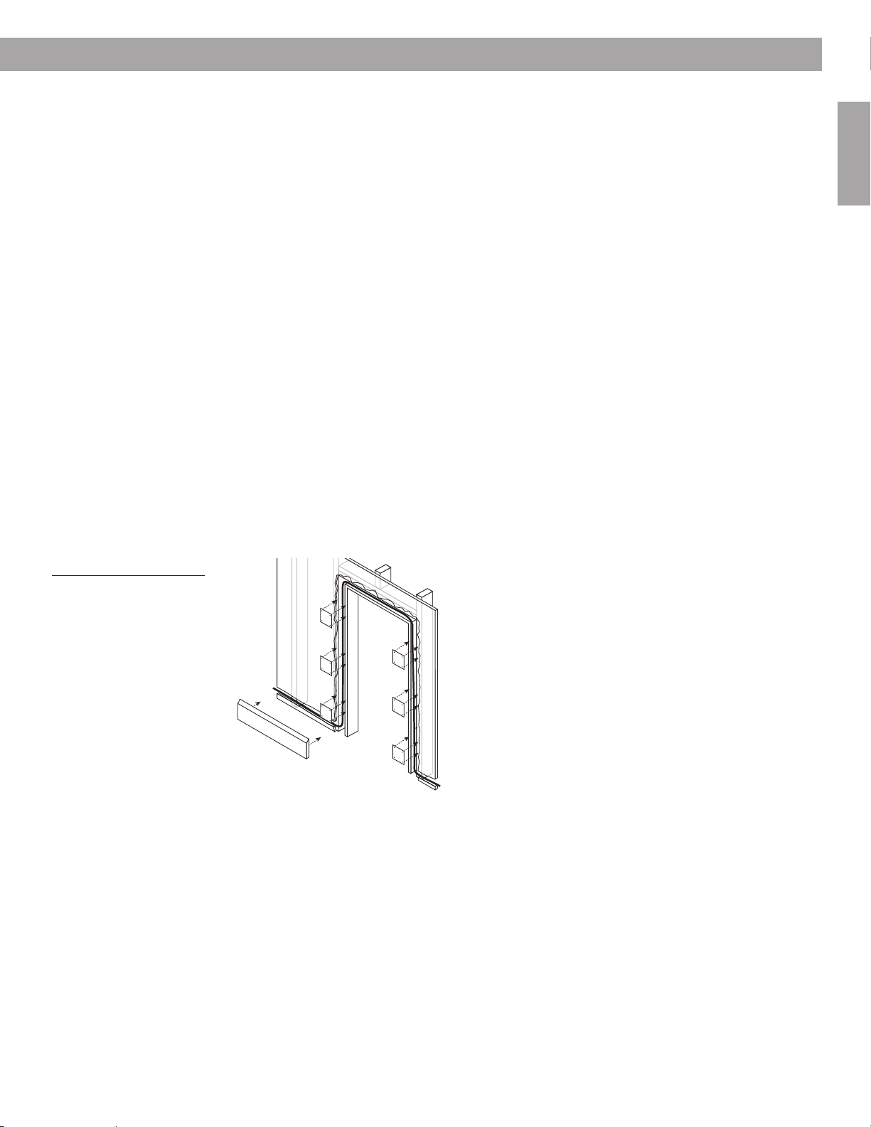
Look for ways to conceal cord outside the walls:
• Along or behind baseboards
• Under carpets (using special flat speaker cord for under-the-rug speaker runs)
• Under doorjams (Figure 11).
1
/2 feet (1.4 m) from a hole.
English
Figure 11
Running cord behind baseboards and a doorjam
Find the easiest path for cord that must run behind the wallboard:
• Choose interior walls, which are less likely to have insulation packed behind the wallboard.
• Use an attic or basement run where possible, so you have easy access and can see where
plumbing, electrical wires, and other impediments occur.
• In slab construction, consider using plenum-rated wire run through heating or air condition-
ing vents.
13
Preparation
English
Figure 12
Running the cord up
through the attic
Getting started
Choose a path for the cord that avoids impediments to drill through. Use a stud finder to
identify inaccessible studs.
It is common to run cord from the speaker location in a wall or ceiling to the attic and through
the wooden top plate that runs horizontally across the top of the vertical studs. From the attic,
you can then run the cord to the spot above the junction box near the receiver or amplifier.
Drill through the top plate at that point and route the cord through the hole and down into the
wall (Figure 12).
Top plate
Open-backed
junction box
Figure 13
Running cord around a corner with nail plates for protection (a) and cutout
pieces as patches (b)
If you must route cord around a corner, you will need to cut out a rectangular piece of wallboard on either side of the joist at that corner. Use each regular-shaped cutout as the patch
for the wall when you finish. By reaching through the cutout, you can notch the joist to make
room for the cord and use nail plates to cover the cord in each notch (Figure 13a).
To patch the wall, reposition the cutout pieces (Figure 13b) and use joint tape and joint compound to hold them in place. When they are dry, sand and paint the area to match surrounding surfaces.
(a)
Nail plates
Wall
Ceiling
Wall
(b)
Cutout pieces
Ceiling
Wall
Wall
14

Steps to Installing
Before you make any holes
Be sure you have read and understand the considerations provided in “Preparation” starting
on page 5, so you can proceed with confidence.
Installation is basically the same, whether you are using these speakers with a rectangular
grille or round grille and installing in a wall or ceiling. There are a few exceptions.
Wherever special instructions apply to ceiling or round-faced speaker installation, those
instructions will appear in a gray box, like this.
CAUTION: If you are unsure of your ability to complete this process, contact a professional
installer.
Allow 30 to 60 minutes to complete the steps that follow.
Drill a pilot hole for testing the wall space
Before you make a sizeable cut into the wallboard, check the space by probing behind
the wall or ceiling through a small pilot hole. Time spent now can help ensure a successful
installation.
Note: If you are working in an exterior wall where there is insulation, it may be difficult to
probe behind a pilot hole. You may prefer to eliminate this step and skip ahead to “Prepare
the wall for inserting the speaker” starting on page 21. Do this only if you can be sure the
insulation is malleable and that nothing else behind the wall will impede the installation.
WARNING: If you believe the insulation behind the wall may be composed of asbestos,
do not drill or cut into that wall. Find a different location for the speakers instead.
English
Using the template for this first step
You will need a sharp pencil for this step.
The template is designed to show where to drill two half-inch (13 mm) pilot holes first, before
you make an opening large enough for the entire speaker. This allows you to probe behind the
wall to make sure your chosen location is spacious enough and there are no unseen materials
blocking the installation.
Notice the dotted lines extending at an angle from the pilot hole to the bottom corners of
the DO NOT CUT area on the template. Use them as a guideline for testing the area below the
pilot hole to make sure it is spacious enough behind the hole for the length and width of the
speaker enclosure.
To position the template
1. Select a spot on the wall or ceiling where you want the center of the speaker grille.
For ceiling installations, carefully consider how the position of the speaker enclosure
behind the wallboard affects the orientation of the Bose
tain a consistent logo orientation, you can remove and rotate the speaker frame as needed
before inserting the speaker into the ceiling hole. See Figure 21 on page 20.
Tip: Remember to allow enough space for the speaker enclosure both above and below the
pilot hole. You may need that second option if you find an impediment in the space below the
hole. This does not apply to exterior walls in cold climate regions, where upside-down
speaker installation is not recommended.
®
logo on the speaker face. To main-
15
Steps to Installing
English &
T
ranslations
O
English &
T
ranslations
English
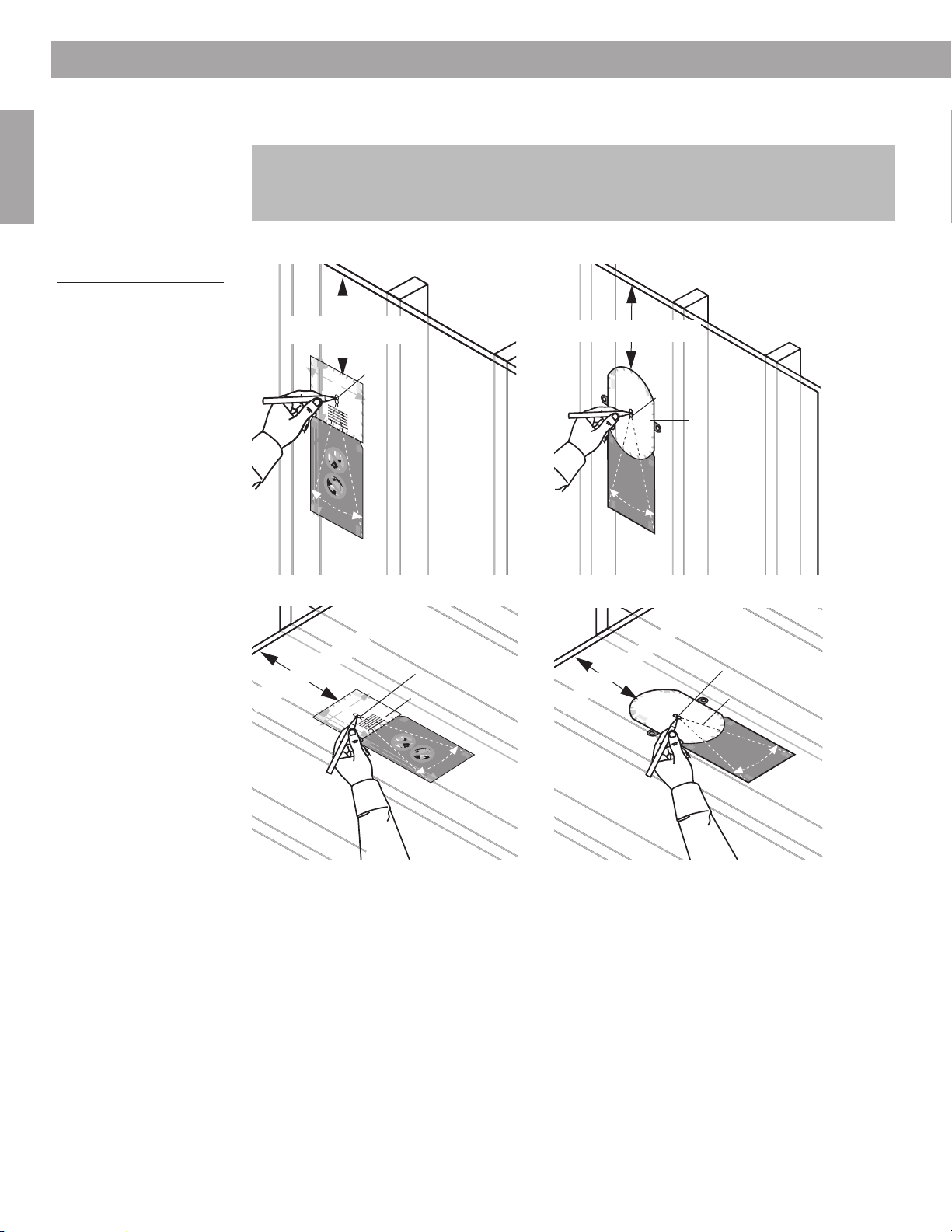
Figure 14
Preparing to cut a pilot hole
2. Center the pilot-hole circles on the selected spot as you press the template to the wall.
3. Use a pencil to trace around the inside of the circles (Figure 14).
Round-faced speakers require additional clearance holes on either side of the speaker
hole. Draw those circles as well as the pilot hole circles now. However, you may prefer to
drill those holes only after you have successfully explored behind the pilot hole and know
there are no impediments to installing the speaker there.
4. Remove the template.
At least 9" (22.9 cm)
T
A
P
E
H
E
R
E
W
A
R
N
surfaces that have hazards
IN
G
: Make sure the spot chosen is safe for c
concealed behind them. If you are not sure, consult a professional installer
before you proceed.
WHITE CUT OUT AREA
W
A
R
N
wiring, conduits or plumbing, concealed behind them. If you are not sure, consult a professional installer before you proceed.
IN
G
: Make sure the spot chosen is safe for cutting. Do not cut through surfaces that have hazards, such as electrical
W
A
R
N
drilling. Do not cut through surfaces that have hazards
IN
G
: Make sure the spot chosen is safe for
concealed behind them, such as electrical wiring,
conduits or plumbing. If you are not sure, consult a
professional installer before you proceed.
1
5
/
"
2
W
A
R
N
spot chosen is safe for
IN
drilling. Do not c
surfaces that ha
concealed behind them,
such as electrical wiring,
conduits or plumbing. If
are not sure, c
professional installer before
you proceed.
W
A
R
N
for drilling. Do not cut through surfaces that have
IN
G
: Make sure the spot chosen is s
hazards concealed behind them, such as
electrical wirin
are not sure, consult a professional
g, conduits or plumbin
before you proceed.
T
A
P
E
H
E
R
E
CUT AROUND
GRAY AREA
1
1
4
/
"
(3
2
6
.9
9
"
c
(2
m
2
.9
c
m
)
CUT AROUND
GRAY AREA
CUT AROUND
GRAY AREA
T
CUT AROUND
A
P
E
H
E
R
E
GRAY AREA
At least 9" (22.9 cm)
TAPE
HERE
, such as electrical wiring, conduits or plumbing,
utting. Do not cut through
1
8
/
"
1
(2
6
0
.5
T
c
T
ra
A
n
m
sla
)
tio
n
s b
H
E
e
lo
R
w
(1
4
c
m
W
)
A
R
N
drilling. Do not cut through surfaces that have hazards
IN
G
G
: Make sure the spot chosen is safe for
:
Make sure the
concealed behind them, such as electrical wiring,
Pilot Hole
conduits or plumbing. If you are not sure, consult a
professional installer before you proceed.
ut through
ve hazards
onsult a
you
W
A
R
N
sure the spot chosen
IN
G
: Make
is safe for drillin
not cut through
surfaces that have
g. Do
hazards concealed
afe
behind them, such
as electrical wiring,
g. If you
installer
conduits or
plumbing. If you are
not sure, consult a
professional installer
before you proceed.
W
A
R
N
chosen is safe for drilling. Do not cut
IN
G
:
Make sure the spot
through surfaces that have hazards
concealed behind them, such as
DO NOT
electrical wiring, conduits or plumbing.
If you are not sure, consult a
professional installer before you
proceed.
English & Translations
DO NOT
CUT AROUND
)
GRAY AREA
T
A
H
DO NOT
DO NOT
CUT AROUND
GRAY AREA
DO NOT
DO NOT
CUT AROUND
GRAY AREA
DO NOT
DO NOT
CUT AROUND
GRAY AREA
T
A
P
E
H
E
R
E
TAPE
HERE
Make sure the spot chosen is safe for
:
w
G
lo
e
" (20.5 cm)
IN
b
N
6
s
1
/
1
n
R
o
A
i
t
a
W
8
l
s
n
a
drilling. Do not cut through surfaces that have hazards
r
T
concealed behind them, such as electrical wiring,
conduits or plumbing. If you are not sure, consult a
professional installer before you proceed.
WARNING: Make sure the spot chosen is safe for cutting. Do not cut through
surfaces that have hazards, such as electrical wiring, conduits or plumbing,
concealed behind them. If you are not sure, consult a professional installer
t H
before you proceed.
ilo
P
Make sure the spot chosen is safe for cutting. Do not cut through surfaces that have hazards, such as electrical
:
G
IN
N
R
Make sure the spot chosen is safe for
:
A
G
W
IN
wiring, conduits or plumbing, concealed behind them. If you are not sure, consult a professional installer before you proceed.
N
R
A
W
WHITE CUT OUT AREA
drilling. Do not cut through surfaces that have hazards
concealed behind them, such as electrical wiring,
" (14 cm)
conduits or plumbing. If you are not sure, consult a
1
/
2
professional installer before you proceed.
5
Make sure the
:
G
IN
N
R
A
W
spot chosen is safe for
drilling. Do not cut through
surfaces that have hazards
concealed behind them,
such as electrical wiring,
conduits or plumbing. If you
are not sure, consult a
professional installer before
you proceed.
Make sure the spot chosen is safe
:
G
IN
N
R
A
W
for drilling. Do not cut through surfaces that have
hazards concealed behind them, such as
electrical wiring, conduits or plumbing. If you
are not sure, consult a professional installer
before you proceed.
Pilot hole
P
E
E
WHITE CUT OUT AREA
P
E
E
R
E
Make
:
G
N
I
N
R
A
W
sure the spot chosen
is safe for drilling. Do
not cut through
surfaces that have
hazards concealed
behind them, such
as electrical wiring,
conduits or
le
plumbing. If you are
o
not sure, consult a
professional installer
DO NOT
CUT AROUND
GRAY AREA
TAPE
HERE
14
Template
Or
WHITE CUT OUT AREA
Make sure the spot
:
G
IN
before you proceed.
N
R
A
W
chosen is safe for drilling. Do not cut
through surfaces that have hazards
concealed behind them, such as
electrical wiring, conduits or plumbing.
If you are not sure, consult a
professional installer before you
TAPE
proceed.
HERE
DO NOT
CUT AROUND
GRAY AREA
English & Translations
" (36.9 cm)
1
/
2
DO NOT
CUT AROUND
9" (22.9 cm)
GRAY AREA
Pilot hole
Template
DO NOT
CUT AROUND
GRAY AREA
DO NOT
CUT AROUND
GRAY AREA
DO NOT
DO NOT
CUT AROUND
CUT AROUND
GRAY AREA
DO NOT
CUT AROUND
GRAY AREA
TAPE
HERE
At least 7
Or
1
/
" (18.1 cm)
8
TAPE
HERE
WARNING: Make sure the spot chosen is s
Do not cut through surfaces that have
electrical wiring, conduits or plumbing, conceal
them. If you
before you proceed.
are not sure, consult a professional installer
afe for cutting.
hazards, such as
WARNING: Make sure the spot chosen is safe for cutting. Do not cut through surfaces that have hazards, such as electrical
wiring, conduits or plumbing, concealed behind them. If you are not sure, consult a professional installer before you proceed.
ed behind
Translations below
WHITE CUT OUT AREA
WARNING: Make sure the spot chosen is safe for
drilling. Do not cut through surfaces that have hazards
concealed behind them, such as electrical wiring,
conduits or plumbing. If you are not sure, consult a
professional installer before you proceed.
WARNING: Make sure the spot chosen is safe for
drilling. Do not cut through surfaces that have hazards
concealed behind them, such as electrical wiring,
conduits or plumbing. If you are not sure, consult a
WARNING: Make
professional installer before you proceed.
sure the spot chosen
is safe for drilling. Do
not cut through
surfaces that have
hazards concealed
P
behind them, such
ilo
as electrical wiring,
t H
conduits or
plumbing. If you are
o
not sure, consult a
le
professional installer
before you proceed.
WARNING: Make sure the spot
chosen is safe for drilling. Do not cut
through surfaces that have hazards
concealed behind them, such as
electrical wiring, conduits or plumbing.
If you are not sure, consult a
professional installer before you
proceed.
TAPE
HERE
English &
T
ranslations
DO NOT
CUT AROUND
GRAY AREA
DO NOT
CUT AROUND
CUT AROUND
GRAY AREA
GRAY AREA
DO NOT
CUT AROUND
CUT AROUND
GRAY AREA
GRAY AREA
DO NOT
CUT AROUND
CUT AROUND
GRAY AREA
GRAY AREA
CUT AROUND
TAPE
HERE
GRAY AREA
TA
H
E
P
R
E
E
Pilot hole
WARNING: Make
sure the spot chosen
WARNING: Make
is safe for drilling. Do
sure the spot chosen
not cut through
is safe for drilling. Do
surfaces that have
not cut through
hazards concealed
surfaces that have
behind them, such
hazards concealed
as electrical wiring,
behind them, such
conduits or
as electrical wiring,
plumbing. If you are
conduits or
not sure, consult a
plumbing. If you are
professional installer
not sure, consult a
before you proceed.
professional installer
before you proceed.
WARNING: Make sure the spot
chosen is safe for drilling. Do not cut
through surfaces that have hazards
WHITE CUT OUT AREA
concealed behind them, such as
electrical wiring, conduits or plumbing.
If you are not sure, consult a
professional installer before you
proceed.
TAPE
HERE
DO NOT
DO NOT
DO NOT
DO NOT
TAPE
HERE
Template
r
" (18.1 cm)
1
/
8
TAPE
HERE
: Make sure the spot chosen is safe for cutting.
G
At least 7
TAPE
HERE
GRAY AREA
IN
N
R
A
W
Translations below
Do not cut through surfaces that have hazards, such as
E
electrical wiring, conduits or plumbing, concealed behind
E
P
R
them. If you are not sure, consult a professional installer
E
A
before you proceed.
T
H
: Make sure the spot chosen is safe for cutting. Do not cut through surfaces that have hazards, such as electrical
G
IN
N
: Make sure the spot chosen is safe for
AR
W
ING
wiring, conduits or plumbing, concealed behind them. If you are not sure, consult a professional installer before you proceed.
N
AR
W
drilling. Do not cut through surfaces that have hazards
concealed behind them, such as electrical wiring,
conduits or plumbing. If you are not sure, consult a
professional installer before you proceed.
WHITE CUT OUT AREA
W
: Make
G
IN
N
R
A
W
sure the spot chosen
is safe for drilling. Do
not cut through
surfaces that have
hazards concealed
behind them, such
: Make sure the spot chosen is safe for
G
IN
N
AR
drilling. Do not cut through surfaces that have hazards
concealed behind them, such as electrical wiring,
conduits or plumbing. If you are not sure, consult a
professional installer before you proceed.
Pilot H
as electrical wiring,
conduits or
plumbing. If you are
not sure, consult a
professional installer
before you proceed.
NING
AR
W
chosen is safe for drilling. Do not cut
through surfaces that have hazards
: Make sure the spot
concealed behind them, such as
electrical wiring, conduits or plumbing.
If you are not sure, consult a
professional installer before you
ole
proceed.
: Make
G
NIN
: Make
G
AR
IN
W
N
sure the spot chosen
AR
is safe for drilling. Do
W
not cut through
sure the spot chosen
surfaces that have
is safe for drilling. Do
hazards concealed
not cut through
behind them, such
surfaces that have
as electrical wiring,
hazards concealed
conduits or
behind them, such
as electrical wiring,
conduits or
plumbing. If you are
not sure, consult a
E
P
E
A
T
R
E
H
plumbing. If you are
not sure, consult a
professional installer
before you proceed.
professional installer
before you proceed.
AR
W
chosen is safe for drilling. Do not cut
: Make sure the spot
ING
N
through surfaces that have hazards
concealed behind them, such as
electrical wiring, conduits or plumbing.
English &
If you are not sure, consult a
professional installer before you
proceed.
ranslations
T
DO NOT
CUT ARO
WHITE CUT OUT AREA
UND
GRAY AREA
DO NOT
CUT ARO
Pilot hole
Template
E
P
E
A
T
R
E
H
DO NOT
CUT AROUND
GRAY AREA
DO NOT
CUT AROUND
GRAY AREA
DO NOT
CUT AROUND
GRAY AREA
DO NOT
UND
CUT AROUND
GRAY AREA
UND
DO NOT
CUT ARO
GRAY AREA
DO NOT
CUT AROUND
GRAY AREA
E
P
E
A
T
R
E
H
E
P
E
A
T
R
GRAY AREA
E
H
16
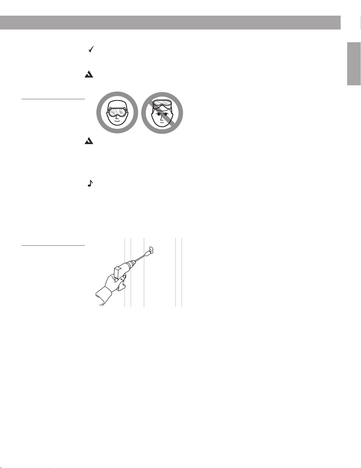
Figure 15
Caution against drilling
without eye protection
Steps to Installing
Drilling the pilot hole
You will need a half-inch spade bit and power drill, or a special rotary cutting tool for this
step.
Using the proper equipment and protection is important.
WARNING: Use eye protection and be sure to observe all safety precautions while using the
drill or cutting tool (Figure 15).
WARNING: Make sure the spot chosen is safe for cutting. Do not cut through surfaces that
may have hazards such as electrical wiring, conduits, or plumbing concealed behind them.
Follow all other safety precautions.
1. Center the tip of the drill bit in the top circle you have drawn).
2. Drill completely through the wallboard to create a hole that you can probe behind.
Note: If you encounter insulation in the wall, it will be difficult, if not impossible, to probe
behind the pilot hole. If you are certain that the location you have chosen is free of hazards
and impediments, you may choose to cut the hole for the speaker anyway, remove some of
the malleable insulation, and proceed from there. Refer to “Prepare the wall for inserting the
speaker” starting on page 21.
3. Drill the second hole just below the first one (Figure 16). This elongates the hole enough
to allow for testing the space for the length of the speaker enclosure.
English
Figure 16
Using a spade bit with the
power drill to create the
pilot hole
17
Steps to Installing
14
1
/
4
inches
(36.2 cm)
4
3
/
4
inches
(12 cm)
3 inches (7.6 cm)
4
1
/
8
inches
(10.5 cm)
English
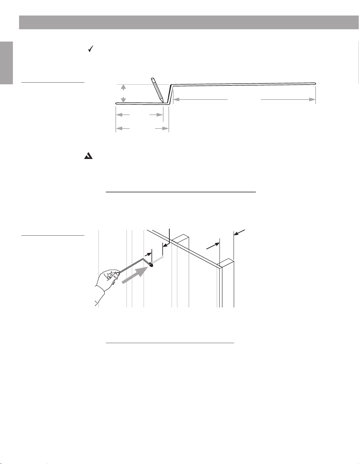
Figure 17
A 22-inch (55.9 cm) length
of sturdy wire bent in two
places
Testing the space behind the hole
You need a tape measure and a sturdy wire (such as a straightened coat hanger)
22 inches (55.9 cm) in length for this step.
1. Bend the wire as shown in Figure 17.
Tip: For greater accuracy, make the first bend a little long, measure again, and cut off the
extra length at that end.
WARNING: If there is any possibility of electrical wiring in the space behind the wallboard,
wrap the wire with electrical tape to prevent electric shock.
2. Make a mark 41/8 inches (10.5 cm) from the short end as an indicator of the proper frontto-back depth of the hole.
3. Use the bent wir
Insert the short end of the wire into the hole and straight back (Figure 18). Probe to make
sure nothing impedes inserting this end to a depth of 4
that the space behind the wallboard is deep enough for the front-to-back speaker
dimension.
e to test for enough depth, front-to-back:
1
/8 inches (10.5 cm). This indicates
Figure 18
Checking the space for the
depth of the speaker
1
"
/
8
4
1
"
/
8
4
(10.5 cm)
(10.5 cm)
• If the wire goes in without a problem, proceed to step 4, below.
1
• If you cannot insert the wire to the 4
/8-inch (10.5 cm) mark, you need to drill a new pilot
hole elsewhere. Then repeat step 3.
4. Use the wir
e again to test the width, side-to-side:
With the short end still in the hole, reposition it (as shown in Figure 19) and rotate it 360˚
around the hole. This indicates if the wall space is wide enough on each side of the hole
for the side-to-side dimension of the speaker.
18
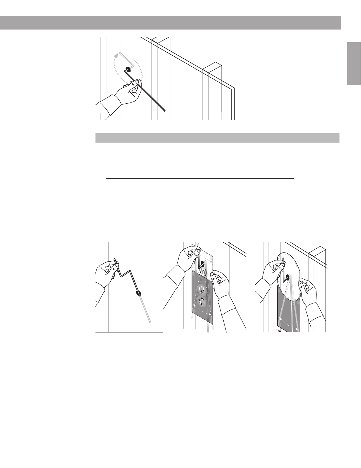
Figure 19
(a)
English &
T
ranslations
Checking the space for the
width of the speaker
Steps to Installing
360˚
• If the wire goes around the 360˚ arc without a problem, proceed to step 5 below.
Round-faced speakers require an additional 2 inches of clearance above the speaker.
• If you cannot rotate the wire all the way around up to the first bend, you need to drill a
new pilot hole elsewhere. Then repeat the preceding steps 3 and 4.
Now remove the wire.
5. Use the long end of the wire to check for enough length below the hole:
Holding the short end of the wire, insert the long end into the wall or ceiling and straight
down from the hole (Figure 20a).
English
Figure 20
Inserting the long end of the
wire (a) and sweeping from
side to side to check the
length (b)
Tip: You may want to use the template for this step, as shown in Figure 20b.
With the long end of the wire still in the hole, sweep it from side to side in a curve as
shown on the template. This indicates if the wall or ceiling space is long enough and
wide enough at the far end.
Tip: When testing for length, move the wire near the wall or ceiling, then farther back from it.
(b)
TAPE
HERE
WARNING: Make sure the spot chosen is safe for cutting. Do not cut through
surfaces that have hazards, such as electrical wiring, conduits or plumbing,
concealed behind them. If you are not sure, consult a professional installer
before you proceed.
WHITE CUT OUT AREA
W
A
R
N
wiring, conduits or plumbing, concealed behind them. If you are not sure, consult a professional installer before you proceed.
IN
G
: Make sure the spot chosen is safe for cutting. Do not cut through surfaces that have hazards, such as electrical
W
1
A
8
R
N
drilling. Do not cut through surfaces that have hazards
/
IN
G
" (20.5 cm)
: Make sure the spot chosen is safe for
1
6
concealed behind them, such as electrical wiring,
T
conduits or plumbing. If you are not sure, consult a
TAPE
ra
n
s
la
tio
professional installer before you proceed.
n
s
HERE
b
e
lo
w
1
5
/
" (14 cm)
2
W
A
W
R
A
N
R
drilling. Do not cut through surfaces that
IN
N
spot chosen is safe for
IN
G
G
: Make sure the spot chosen is safe for
: Make sure the
concealed behind them, such as electrical wiring,
drilling. Do not cut through
Pilot Hole
conduits or plumbing. If you are not sure, consult a
surfaces that have hazards
professional installer before you proceed.
concealed behind them,
such as electrical wiring,
conduits or plumbing. If you
have hazards
are not sure, consult a
professional installer before
you proceed.
W
A
R
N
W
for drilling. Do not cut through surfaces that have
IN
A
G
R
: Make sure the spot chosen is safe
N
sure the spot chosen
IN
hazards concealed behind them, such as
G
: Make
is safe for drilling. Do
electrical wiring, conduits or plumbing. If you
not cut through
are not sure, consult a professional installer
surfaces that have
before you proceed.
hazards concealed
behind them, such
as electrical wiring,
conduits or
plumbing. If you are
not sure, consult a
professional installer
before you proceed.
TAPE
W
WHITE CUT OUT AREA
A
R
N
chosen is safe for drilling. Do not cut
IN
HERE
G
: Make sure the spot
through surfaces that have hazards
concealed behind them, such as
DO NOT
electrical wiring, conduits or plumbing.
If you are not sure, consult a
CUT AROUND
professional installer before you
proceed.
English & Translations
GRAY AREA
14
1
DO NOT
/
" (36.9 cm)
2
9" (22.9 cm)
CUT AROUND
GRAY AREA
TAPE
HERE
DO NOT
CUT AROUND
GRAY AREA
DO NOT
CUT AROUND
GRAY AREA
DO NOT
CUT AROUND
GRAY AREA
DO NOT
CUT AROUND
GRAY AREA
DO NOT
TAPE
CUT AROUND
HERE
GRAY AREA
DO NOT
CUT AROUND
GRAY AREA
TAPE
HERE
Or
TAPE
HERE
WARNING: Make sure the spot chosen is safe for cutting.
Do not cut through surfaces that have hazards, such as
electrical wiring, conduits or plumbing, concealed behind
them. If you are not sure, consult a professional installer
before you proceed.
W
A
R
N
wiring, conduits or plumbing, concealed behind them. If you are not sure, consult a professional installer before you proceed.
IN
G
: Make sure the spot chosen is safe for cutting. Do not cut through surfaces that have hazards, such as electrical
T
ra
n
sla
tio
n
W
s b
e
lo
w
W
A
HITE CUT OUT AREA
R
N
drilling. Do not cut through surfaces that have hazards
IN
G
: Make sure the spot chosen is safe for
concealed behind them, such as electrical wiring,
conduits or plumbing. If you are not sure, consult a
professional installer before you proceed.
W
A
R
N
drilling. Do not cut through surfaces
IN
G
: Make sure the spot chosen is safe for
concealed behind them, such as electrical wiring,
conduits or plumbing. If you are not sure, consult a
W
A
R
N
professional installer before you proceed.
sure the spot chosen
IN
G
: Make
is safe for drilling.
not cut through
that have hazards
surfaces that have
Do
hazards concealed
P
behind them, such
ilo
as electrical wiring,
t H
conduits or
plumbing. If you are
o
not sure, consult a
le
professional installer
before you proceed.
W
A
W
R
A
N
chosen is sa
R
IN
N
sure the spot chosen
W
G
IN
A
: Make sure the spot
through surfaces that have hazards
G
R
: Make
N
is safe for drilling. Do
sure the spot chosen
IN
concealed behind them, such as
fe for drilling. Do not cut
G
: Make
not cut through
is safe for drilling. Do
electrical wiring, conduits or plumbi
surfaces that have
not cut through
If you are not sure, consult a
hazards concealed
surfaces that have
professional installer before you
behind them, such
hazards concealed
proceed.
as electrical wiring,
behind them, such
conduits or
as electrical wiring,
ng.
plumbing. If you
conduits or
not sure, consult a
plumbing. If you are
professional installer
not sure, consult a
are
before you proceed.
professional installer
before you proceed.
W
A
R
N
chosen is safe for drilling. Do
IN
G
: Make sure the spot
TAPE
through surfaces that have hazards
concealed behind them, such as
HERE
electrical wiring, conduits or plumbing.
If you are not sure, consult a
professional installer before you
proceed.
English &
T
ranslations
DO NOT
CUT AROUND
GRAY AREA
DO NOT
CUT AROUND
DO NOT
CUT AROUND
GRAY AREA
GRAY AREA
DO NOT
CUT AROUND
DO NOT
CUT AROUND
GRAY AREA
GRAY AREA
DO NOT
CUT AROUND
DO NOT
CUT AROUND
GRAY AREA
GRAY AREA
DO NOT
CUT AROUND
TAPE
HERE
GRAY AREA
T
H
A
E
P
R
E
E
T OUT AREA
ITE CU
H
W
not cut
TAPE
HERE
• If the wire goes in and sweeps from side to side at the far end without a problem, proceed to the next major step: “Prepare the wall for inserting the speaker” starting on
page 21.
• If you find an impediment below the pilot hole, and you are working in an interior wall,
reinsert the wire upward. If there are no impediments above the pilot hole, you can
install the speaker upside-down. If you are working in an exterior wall, installing the
speaker upside-down is not recommended. In this case, if you find an impediment you
need to drill a new pilot hole elsewhere. Then repeat the preceding steps 3, 4, and 5.
19
Steps to Installing
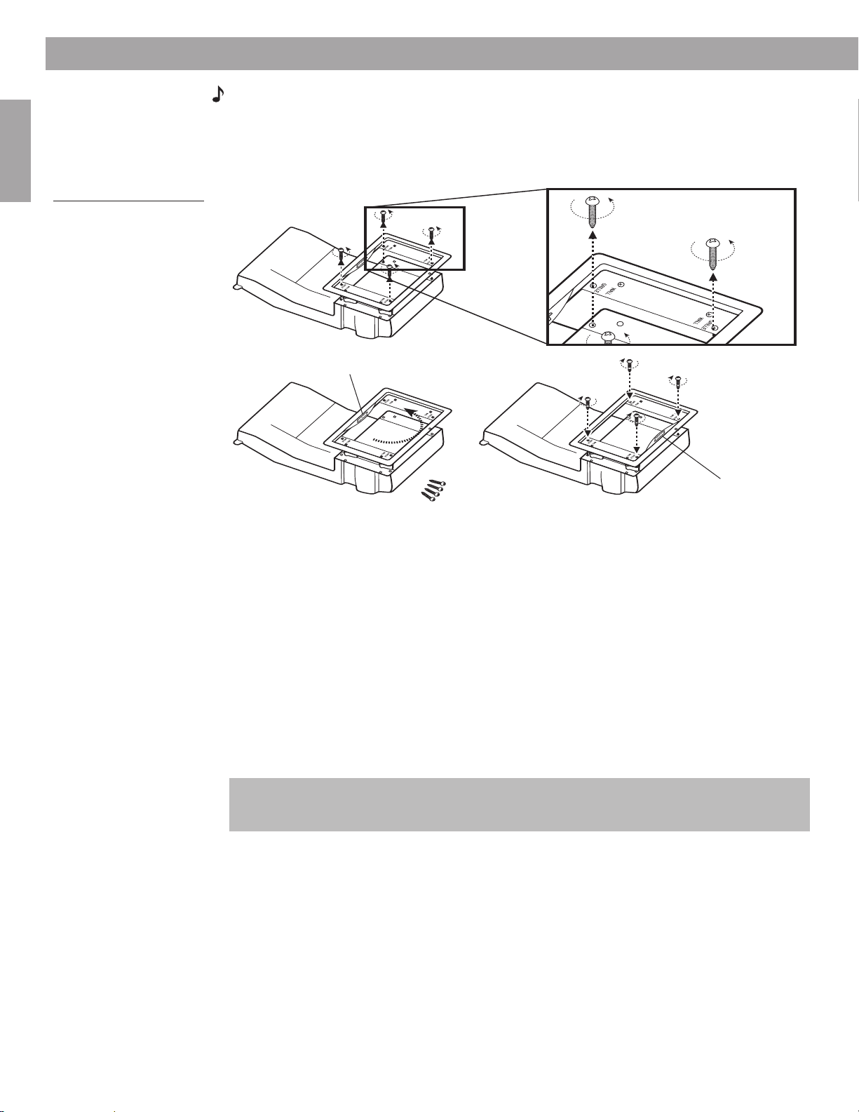
Logo
Logo
English
Figure 21
Removing the speaker
frame to reorient it as
needed
Note: To position the logo right-side-up if you insert the speaker upside-down, remove the
outer frame from the face of the speaker, rotate it 180˚, then reattach the frame. There are four
speaker frame screws, labeled GRILLE, that hold the frame in place. They should not be confused with the dogleg clamp screws that are labeled WALL (Figure 21). Those screws hold
the dogleg clamps on the frame.
• If you cannot insert the entire length of the wire straight up in an interior wall, and
sweep it from side to side as shown on the template, you need to drill a new pilot hole
elsewhere. Then repeat the preceding steps 3, 4, and 5.
Repairing a pilot hole
If you need to patch the pilot hole, you can fill it with spackle. You may need to let the spackle
dry, then add more until the hole is slightly overfilled. When it is thoroughly dry, sand the area
to bring it back flush with the wall.
Passing the pilot hole test
If you have successfully determined that this location will work for one speaker, test the wall
or ceiling for the second speaker before making any larger holes. Refer to “Drill a pilot hole for
testing the wall space” starting on page 15 and repeat those steps.
If the location for the first speaker is fine, but the second is not, you may want to relocate
both speakers.
Round-faced speakers require additional clearance holes on either side of the main
speaker hole. If you have marked but have not drilled those holes yet, do so when it is clear
you will be installing a speaker in that spot.
20
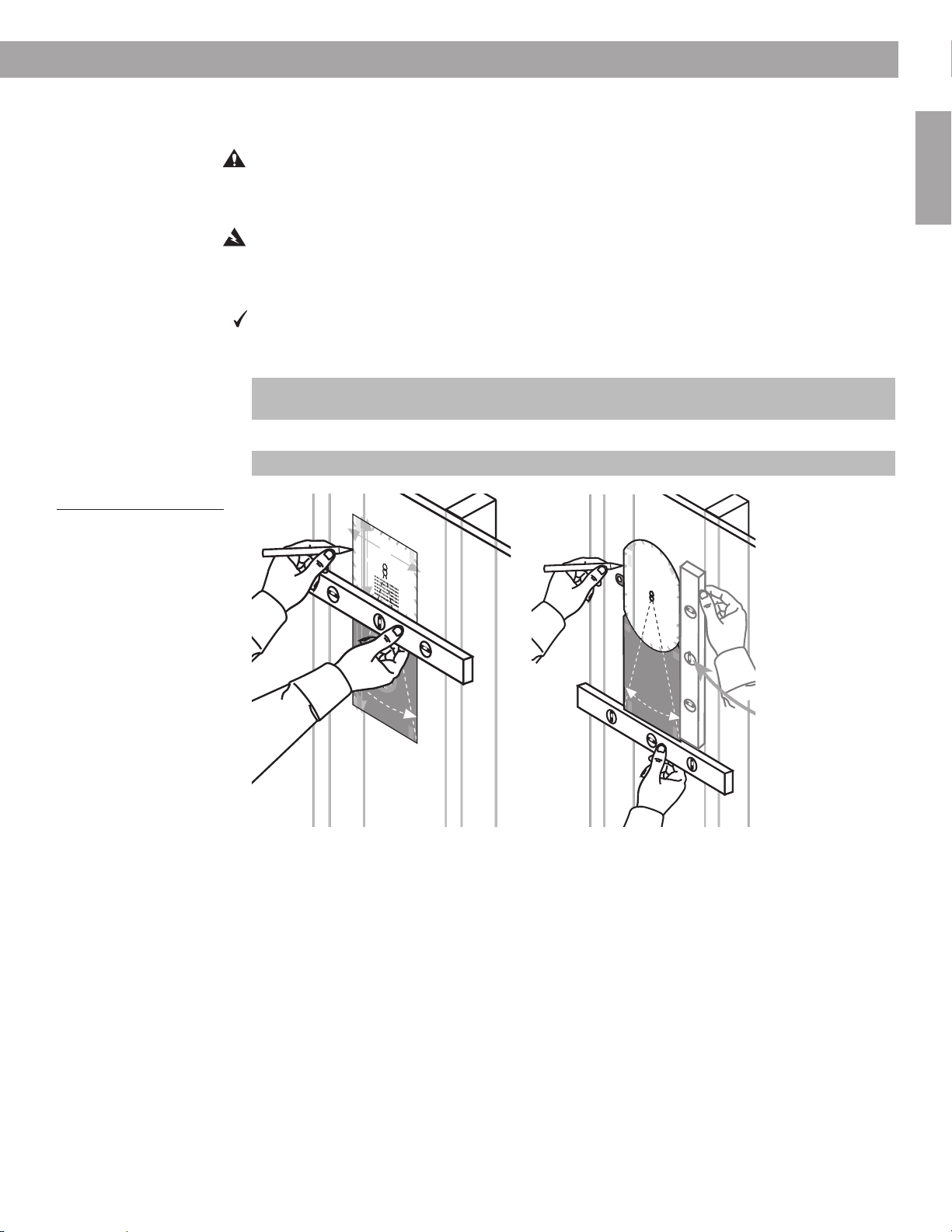
Prepare the wall for inserting the speaker
English &
T
ranslations
Use care in the steps that follow to ensure satisfaction with the end result.
CAUTION: Now is a good time to reconsider your comfort level with this job. If you have
doubts about cutting into or running cord behind the wall, it’s best to stop here. Then you can
contact a professional installer, describe the job, and request a cost estimate before engaging the installer’s services.
WARNING: If you believe insulation in a wall may contain asbestos, do not cut into the wall.
Find a different location for installing the speakers instead.
Using the template a second time
You need a carpenter’s level, a sharp pencil, and optional tape with the template to com-
plete this step.
1. Position the template carefully over the pilot hole where you want to install one speaker.
For the round-faced speaker, you may want to bend the small tabs on either side of the
main cutout area behind it before positioning the template on the wall or ceiling.
2. Make sure the template is level (Figure 22).
Positioning the round-faced speaker on a ceiling does not require using a level.
Figure 22
Making sure the template is
straight
TAPE
HERE
WARNING: Make sure the spot chosen is safe for cutting. Do not cut through
surfaces that have hazards, such as electrical wiring, conduits or plumbing,
concealed behind them. If you are not sure, consult a professional installer
before you proceed.
WHITE CUT OUT AREA
WARNING: Make sure the spot chosen is safe for cutting. Do not cut through surfaces that have hazards, such as electrical
wiring, conduits or plumbing, concealed behind them. If you are not sure, consult a professional installer before you proceed.
WARNING: Make sure the spot chosen is safe for
drilling. Do
1
8
/
concealed behind them, such as electrical wiring,
" (20.5 cm)
16
not cut through surfaces
conduits or plumbing. If you are not sure, consult a
Translations below
professional installer before you proceed.
WARNING: Make sure the
spot chosen is safe for
drilling. Do not cut through
surfaces that have hazards
concealed behind them,
such as electrical wiring,
conduits or plumbing.
are not sure, consult a
professional installer
WARNIN
you proceed.
for drilling. Do not cut through
G: Make sure the spot chosen is safe
hazards concealed behind them, such as
electrical wi
are not sure, consu
ring, conduits or plumbing. If yo
before you proceed.
lt a professional installer
TAPE
HERE
14
1
/
" (36.9 cm)
2
9" (22.9 cm
)
TAPE
HERE
1
5
/
" (14 cm
2
)
If you
before
surfaces that have
u
DO NOT
CUT AROUND
GRAY AREA
DO NOT
CUT AROUND
GRAY AREA
DO NOT
CUT AROUND
GRAY AREA
DO NOT
CUT AROUND
GRAY AREA
that have hazards
Pilot H
English &
WARNING: Make sure the spot chosen is safe for
drilling. Do not cut through surfaces that have hazards
concealed behind them, such as electrical wiring,
conduits or plumbing. If you are not sure, consult a
professional installer before you proceed.
ole
WARNING: Make
sure the spot chosen
is safe for drilling. D
not cut through
surfaces that have
hazards concealed
behind them, such
as electrical wiring,
conduits or
plumbing. If you are
not sure, consult a
professional installer
before you procee
W
ARNING: Make sure the spot
chosen is safe for drilling.
through surfaces that have hazards
concealed behind them, such as
electrical wiring,
If you are not sure, consult a
professional installer before you
proceed.
Translations
DO NOT
CUT AROUND
GRAY AREA
DO NOT
CUT AROUND
GRAY AREA
DO NOT
CUT AROUND
GRAY AREA
DO NOT
CUT AROUND
GRAY AREA
conduits or plumbing.
TAPE
HERE
o
d.
Do not cut
TAPE
HERE
TAPE
HERE
WHITE CUT OUT AREA
Or
TAPE
HERE
WARNING: Make sure the spot chosen is safe for cutting.
Do not cut through surfaces that have hazards, such as
electrical wiring, conduits or plumbing, concealed behind
them. If you
before you proceed.
are not sure, consult a
W
A
R
N
wiring, conduits or plumbing, concealed behind them. If you are not sure, consult a professional installer before you proceed.
IN
G
:
professional installer
Make sure the spot chosen is safe for cutting. Do not cut through surfaces that have hazards, such as electrical
TAPE
HERE
T
r
a
n
s
l
a
ti
o
n
W
s
b
e
lo
w
W
A
H
R
N
drilling. Do not cut t
IN
G
IT
:
concealed behind them, such as electrical wiring,
Make sure the spot chosen is safe for
conduits or plumbing. If you are not sure, consult a
E
hrough surfaces that have hazards
professional installer before you proceed.
C
U
T
O
W
A
U
R
N
drilling. Do not cut
IN
G
T
:
concealed behind them, such as electrical wiring,
Make sure the spot chosen is safe for
A
W
conduits or plumbing. If you are not sure, consult a
A
R
N
through surfaces that have hazards
professional installer before you proceed.
sure the spot ch
IN
G
R
:
Make
is safe for drilling. Do
E
not cut through
osen
surfaces that have
A
hazards concealed
P
behind them, such
ilot H
as electrical wiring,
conduits or
plumbing. If you are
o
not sure, consult a
le
professional installer
before you proceed.
W
A
W
R
A
N
chosen is safe for
R
IN
N
sure the
W
G
IN
A
:
through surfaces that have hazards
G
Make sure the spot
R
:
N
Make
is safe for drilling. Do
sure the spot
I
N
spot chosen
concealed behind them, such as
G
:
Make
not cut through
is safe for drilling. Do
drilling. Do not cut
electrical wiring
surfaces that have
not cut through
chosen
If you are not sure, consult a
hazards concealed
surfaces that have
professional installer before you
, conduits or plumbing.
behind them, such
hazards concealed
proceed.
as electrical wiring,
behind them, such
conduits or
as electrical wiring,
plumbing. If you are
conduits or
not sure, consult a
plumbing. If you are
professional installer
not sure, consult a
before you proceed.
professional installer
before you proceed.
W
A
R
N
chosen is
IN
G
:
TAPE
through surfaces that have hazards
Make sure the spot
safe for drilling.
concealed behind them, such as
HERE
electrical
If you are not sure, consult a
Do not cut
wiring, conduits or plumbing.
professional installer before you
proceed.
English &
T
ranslations
DO NOT
CUT AROUND
GRAY AREA
DO NOT
DO NOT
CUT AROUND
CUT AROUND
GRAY AREA
GRAY AREA
DO NOT
DO NOT
CUT AROUND
CUT AROUND
GRAY AREA
GRAY AREA
DO NOT
DO NOT
CUT AROUND
CUT AROUND
GRAY AREA
GRAY AREA
DO NOT
CUT AROUND
TAPE
HERE
GRAY AREA
HERE
Steps to Installing
A
E
R
A
T
U
O
T
U
C
E
IT
H
W
TAPE
HERE
TAPE
English
3. Tape or hold the template firmly in place as you trace around the sides and upper edge of
the WHITE CUT-OUT AREA portion.
4. Make a dotted line, using the slotted holes along the bottom of the WHITE CUT-OUT
AREA portion, for the bottom edge of the hole.
5. Remove the template.
21
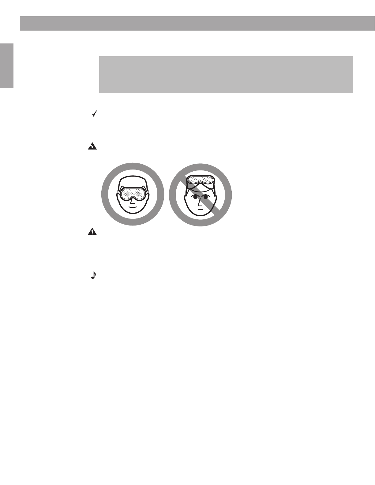
Steps to Installing
English
Figure 23
Caution against drilling
without eye protection
Tip: If necessary, use tape to hold the template temporarily in place (see TAPE HERE on the
template). Then run your pencil along the entire template edge, except where there is tape.
For ceiling installation, notice the orientation of the Bose® logo on the speaker frame.
Make sure it will be oriented as you want it when you position the speaker in the hole you
cut. If you need the logo to face in the opposite direction, you can do so by removing the
speaker frame, rotating it 180˚ and reattaching it to the speaker. Refer to Figure 21 on page
20.
Cutting the speaker hole
You need a small saw or specialized cutting tool (for example, a keyhole or drywall saw)
for this step of the installation.
Be sure to use the proper equipment and follow all safety precautions as you cut through the
wallboard.
WARNING: Use eye protection (Figure 23) and be sure to observe all safety precautions
while using the saw or cutting tool.
CAUTION: Use care in handling tools to avoid damage to the surrounding wall area.
1. Insert the blade into the pilot hole and cut down and at an angle until you reach one pencil line. Or, before you begin cutting, you may prefer to drill holes inside each corner of
the
rectangular outline you have drawn, to simplify the job.
Note: Making the corners perfectly square is not important.
Tip: While it is important to cut carefully, remember that the speaker frame overlaps the
wallboard by
1
/4-inch (0.6 cm) when the speaker is in place. Minor cutting inaccuracies will be
hidden behind that frame.
22
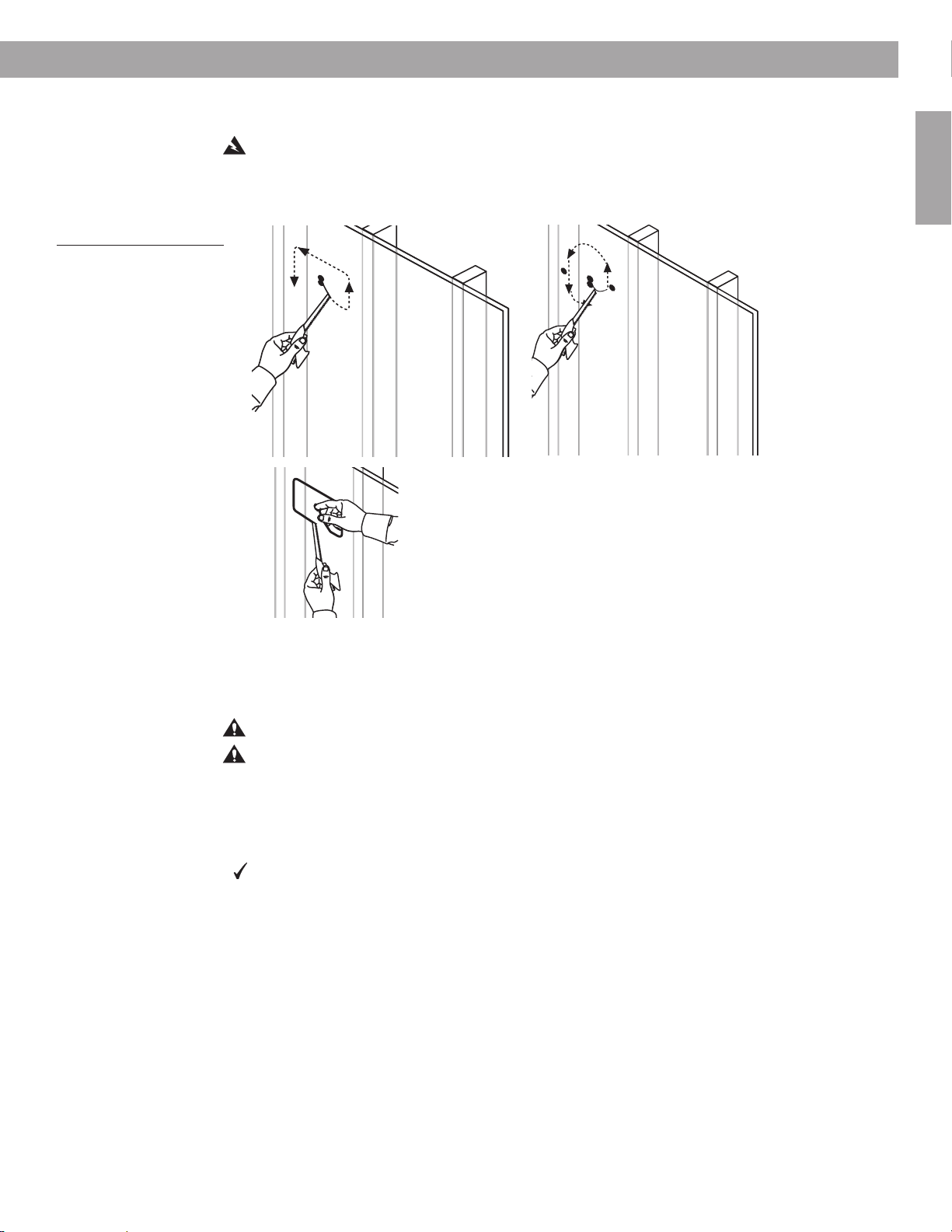
Steps to Installing
2. Cut around three of the four sides of the outline you drew, not all the way around
(Figure 24a).
WARNING: Keep fingers away from the cutting blade.
3. Hook your finger into the pilot hole and then make the final cut (Figure 24b).
4. Using your finger, pull out the piece of wallboard you have just cut.
English
Figure 24
Cutting along the outline
(a), and using a finger to
hold the cutout piece (b)
(a)
(b)
If you encounter insulation behind the wall
You can expect to find insulation in an exterior wall and sometimes it appears in an interior
wall as well. If the insulation found there is malleable, you can cut it and remove some of it to
make room for the speaker. Other types of insulation will be difficult or possibly dangerous to
handle.
CAUTION: Beware of hidden nails when reaching into the wall to remove insulation.
CAUTION: Wear gloves and protection for your mouth, nose, and eyes before handling
insulation that contains fiberglass.
Cut some insulation away from both above and below the speaker hole.
Insert and wire the speaker
You need a Phillips-head screwdriver and optional tape to complete this step.
If your wall is not pre-wired, refer to “Planning to run speaker cord” starting on page 11. When
wire is within reach of the hole you have cut, follow the procedure below:
1. From inside the newly cut speaker hole, locate and pull out 14 inches (36 cm) or more of
the pre-wired speaker cord (Figure 25).
23
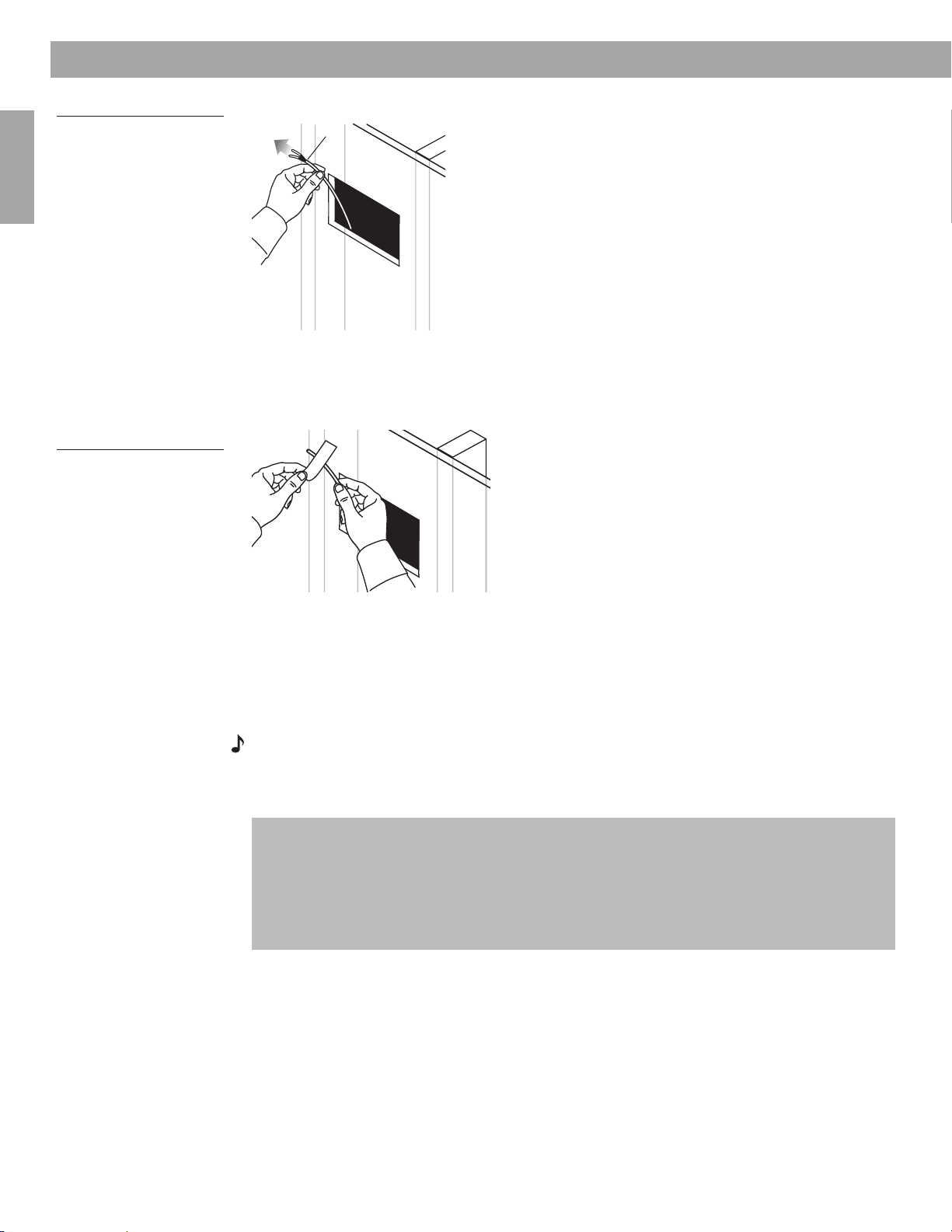
Steps to Installing
Figure 25
Pulling the wire up and out,
to the left
English
Figure 26
Using tape to secure the
wire
At least14 inches
(36 cm) of wire
2. Use tape or the assistance of another person to temporarily affix the loose end of
the wire above and to the left of the hole (Figure 26). This keeps the wire out of the
way until you have the speaker partially inserted in the wall and are ready to make the
connections.
Insert the speaker into the opening
Before you follow the steps below, check to be sure none of the dogleg clamps (two on each
side) are protruding from behind the frame of the speaker. If so, press them back behind the
frame so the speaker will fit into the hole.
Tip: Loosening the screw terminals on the upper left side of the speaker before inserting the
speaker into the hole may save you effort in making the connections.
Note: If you must insert the speaker upside-down due to a lack of space below the hole, you
need to reorient the logo before inserting it into the hole. If you have not done so yet, remove
the outer frame from the face of the speaker, rotate it 180˚, then reattach the frame. Refer to
Figure 21 on page 20.
In ceiling installations, pay attention to the orientation of the Bose® logo on the speaker
frame. Make sure it will be oriented as you want it when you position the speaker in the
speaker hole. If the logo should face in the opposite direction, change that before you insert
the speaker into the hole. Do so by removing the speaker frame, rotating it 180˚, and reattaching it to the speaker. Refer to Figure 21 on page 20.
Also you may notice a draft in the space above the ceiling. To stop the draft, you can wrap
some malleable insulation around the speaker enclosure before inserting it into the wall.
24
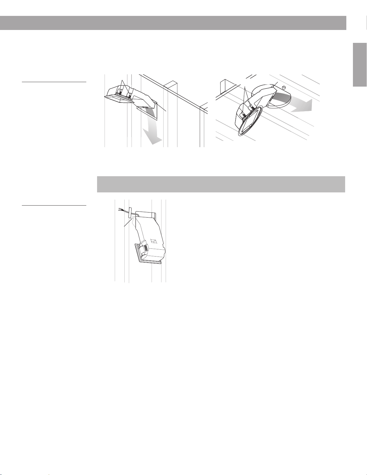
Steps to Installing
1. Use both hands to support the speaker and angle it slightly, so it is diagonal to the hole.
This allows clearance for the wall stops.
2. Insert the bottom of the enclosure through the hole and down part of the way – or up,
depending on your clearance issues (Figure 27).
English
Figure 27
Partially inserting the
rectangular-faced or roundfaced speaker
Figure 28
Speaker held in place by
wall stops
Dogleg clamps
Dogleg clamps
Wall stop
Wall stop
3. Leave the speaker in this partially inserted position, resting on the wall stops that prevent
it from falling out (Figure 28). This allows ready access to the connection terminals on the
upper left-hand side of the speaker.
For ceiling installations, you may feel more secure holding the speaker while making the
connections.
Wall stop
25
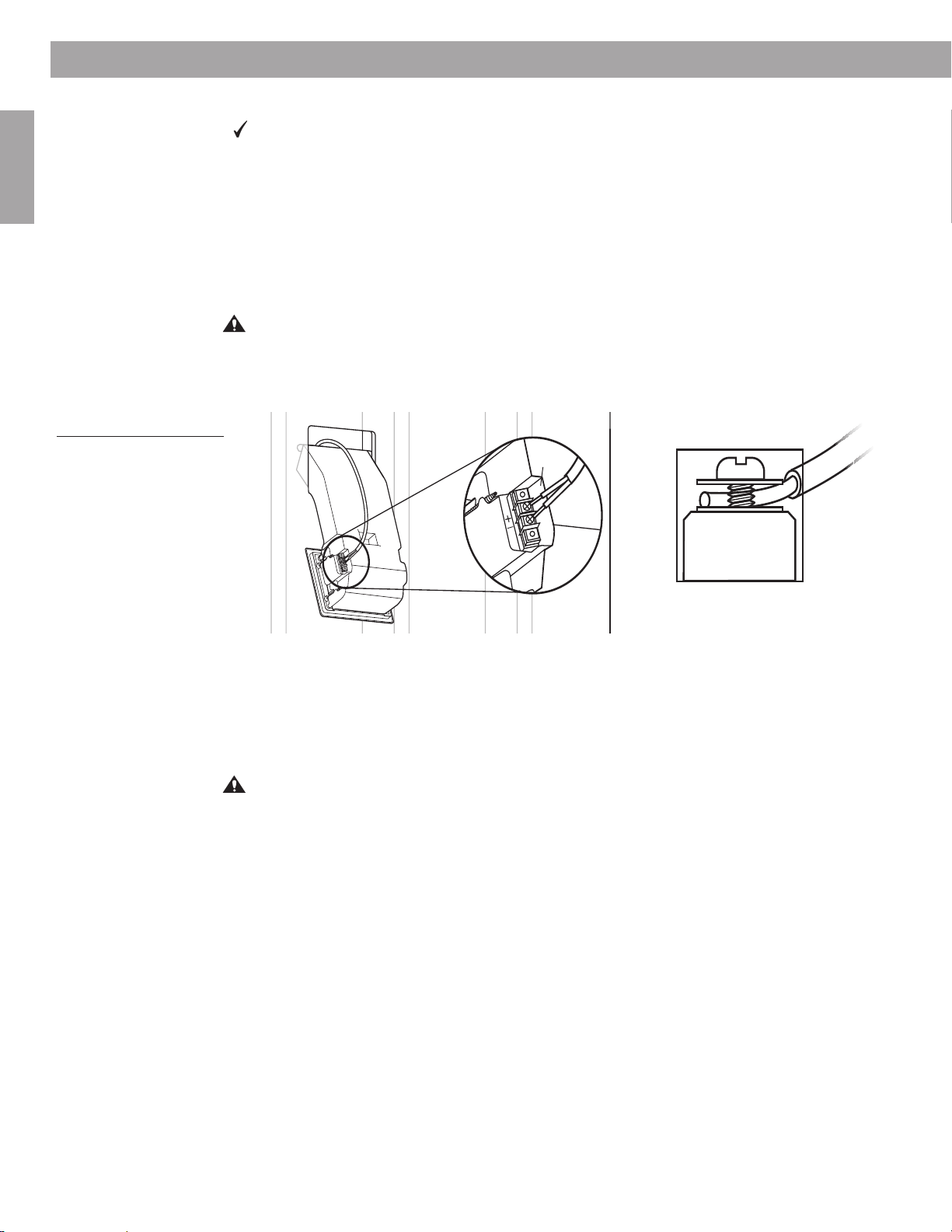
Steps to Installing
+
English
Figure 29
Attaching wires to the
terminals
Make the speaker connections
You need a Phillips-head screwdriver for this step.
Tip: Pay attention to maintaining the proper polarity (+ to + and – to –) with these connections. An error here will adversely affect speaker performance. Also be sure to tighten each
screw securely, but not enough to cause undesirable compression of the wire.
1. If you have not done so earlier, loosen the screws on both terminals.
2. Insert the end of the marked wire (+) into the positive (+) terminal and tighten the screw
(Figure 29).
3. Insert the end of the unmarked wire (–) into the negative (–) terminal and tighten the
screw.
CAUTION: Do not allow exposed wires to brush against each other, which could damage
your components. Trim excess wire and reinsert as necessary.
4. Check for the consistent polarity (+ to + and – to –) of these connections at both the
receiver/amplifier and the speaker.
Test the speaker now
With the connections still within reach, now is a good time to test the speaker to make sure it
functions properly before you secure it in the wall.
It may be preferable to begin installing the second speaker now, before you test either one.
When you get the second speaker connected, you can test both speakers, and make sure
they are both functioning fine before proceeding with the installation steps for each one.
CAUTION: If you are testing the first speaker before the other one is connected, make
sure the wire to that first speaker is the only one connected to the receiver/amplifier. This
will avoid any risk of unattached speaker wires making contact, which can damage the
receiver/amplifier.
26
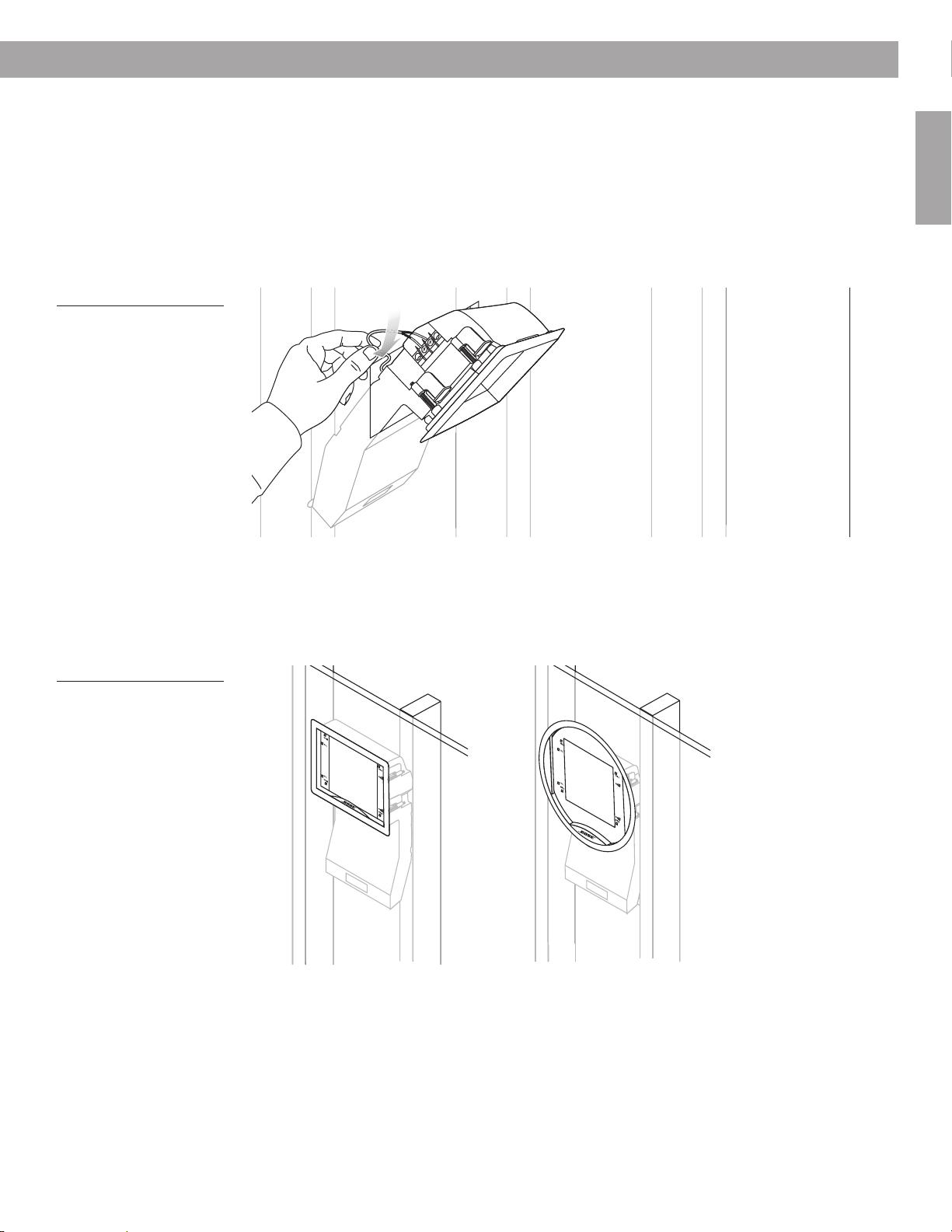
Figure 30
Pushing excess wire behind
the speaker
Steps to Installing
To test the speaker:
1. Turn on the receiver/amplifier and play a piece of music that is familiar to you.
2. Listen for clarity and accuracy of the performance from one speaker.
• If you hear a problem, refer to “Troubleshooting” starting on page 32.
• If the performance sounds fine, test the other speaker, or continue with the installation
steps for this speaker.
When the connections are completed, push any excess wire into the hole behind the speaker
(Figure 30).
English
Figure 31
Positioning the speaker all
the way in the hole
3. Make sure the frame of the speaker is firmly screwed onto the face. The frame prevents
the speaker from slipping all the way into the hole. Refer to Figure 23 on page 22 if you
need to reverse the frame to properly orient the Bose logo on the speaker face.
4. Now push the speaker into the hole until the face is straight and flush with the wall
(Figure 31).
Or
27
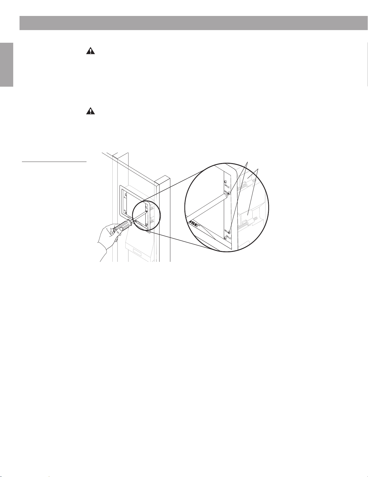
Steps to Installing
Secure the speaker to the wall
CAUTION: If you use a screw gun to tighten any screws, first select the gun’s lowest torque
setting (do not exceed 2-4 inch-pounds or 0.2-0.5 N-m of torque). If the screw does not seat
properly, finish installing the screw at the next highest torque setting, or by hand.
English
When the speaker is positioned inside the hole with the face straight and flat against the wall,
you are ready to tighten the dogleg clamp screws, labeled WALL, along the sides of the
frame. These screws are not to be confused with the screws in each corner of the frame,
which hold the frame on the speaker face. Dogleg clamps exert pressure from inside to hold
the speaker firmly against the wall.
CAUTION: Although they should be thoroughly screwed down, be sure not to overtighten
these screws. Too much compression can crush the wallboard, making it crumble. This
creates uneven surface support and can leave gaps between the speaker face and the wall.
1. Slightly tighten the four dogleg clamp screws (Figure 32) until each one begins to grip.
This is caused by the clamps that swing out and press against the back of the wallboard.
Figure 32
Tightening the dogleg
clamp screws
Dogleg clamp screws
Dogleg clamps
GRILLE
WALL
WALL
GRILLE
2. With your fingers grasping the frame of the speaker, rock it slightly back and forth into
position. Check for even seating of the face before you tighten the screws any further,
and adjust the speaker if it needs to be straightened.
3. When the speaker is straight, tighten each screw.
28
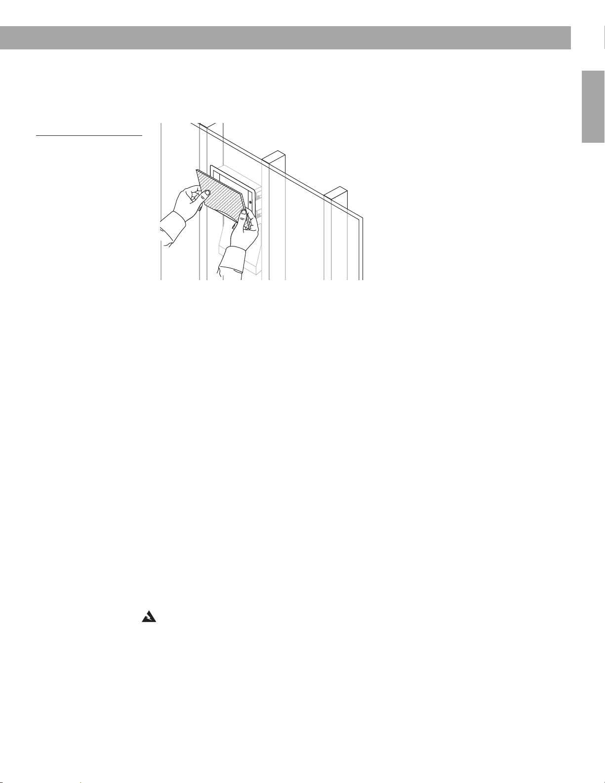
Figure 33
Snapping the grille into
place
Steps to Installing
4. Line up the curved edge of the grille with the curve over the Bose® logo and press that
edge into the speaker frame first (Figure 33).
5. Press the top of the grille firmly into place until you feel some resistance. When the grille
lines up flush with the frame of the speaker, it is seated properly.
If the speaker looks crooked
When you step back from the wall, you may notice that the speaker is not straight. If so, it is
easy to adjust the speaker slightly now:
1. Remove the grille by inserting a thin-bladed tool between the speaker frame and the grille
and carefully prying it out.
2. Slightly loosen each of the four dogleg clamp screws, labeled WALL.
3. Press on the sides of the speaker frame to shift it up or down into the proper position.
4. Stand back to make sure it is straight. Repeat step 3 if it is not.
5. Tighten all four dogleg clamp screws.
6. Reattach the grille to the front of the speaker.
English
When the grille is finally in place
If there are additional speakers to install, repeat the “Steps to Installing,” beginning with “Drill
a pilot hole” on page 17.
If this is your final speaker, congratulations! Turn on the music while you admire your work...
and enjoy the rewards.
Choosing to paint the speakers
The grille and frame of your Virtually Invisible® 191 speakers can be painted before or after the
speaker is installed. This is optional, however, and Bose cannot be responsible for the quality
of adhesion or finish of non-factory applied paints.
There are different techniques for painting the grille and painting the frame. Be sure to use
paint that is appropriate to the technique you choose.
WARNING: Follow all recommended safety procedures for the chemicals involved. This
includes the proper use of eye protection, ventilation systems, respirators or filter masks, and
fire safety equipment if flammable solvents are used.
29

Steps to Installing
English
Painting the grille
It is important to prevent paint from clogging the grille perforations, which can adversely
affect performance. You can use a dry brush technique or choose to spray paint the grille. Do
not use a paint roller, however.
Regardless of the technique you choose:
• Remove the grille from the speaker if it has been installed.
• Before you begin to paint, clean the grille to remove possible contaminants. Even finger-
prints can prevent uniform coverage.
• Check to be sure the paint is distributed evenly and covers the grille thoroughly. If not, you
may need to paint the inside of the grille to fix the problem.
•When it is dry, protect the painted grille with clean cloth or tissue paper until you attach it to
the speaker.
Using a dry brush technique
Unthinned latex paint is appropriate for this method. Be sure to put down enough paper to
cover your work area and allow for repeatedly blotting the brush.
1. Dip the tip of a clean, dry brush in the paint.
2. Stroke across the paper to reduce the amount of paint on the brush. When you can see
individual bristle marks, the brush is ready to use on the grille.
3. Stroke lightly back and forth on the front of the grille, in a horizontal direction, until you
need more paint.
Tip: If paint clogs any of the grille perforations, try angling your stroke to unclog it, or blow
gently on the clog.
4. Repeat the above steps until the outside of the grille is completely covered.
5. Turn the grille 180˚ and repaint the entire surface using back-and-forth strokes again.
Using a spray technique
Latex or oil-based architectural paint requires thinning for use with a siphon-feed spray gun
set for 30 psi (2.1 bar) and for application in a 3- to 5-inch (7.6-12.7 cm) fan pattern. The thinning formula depends on the type of paint you are using.
• Thin vinyl acrylic latex paint as follows:
To 6 parts of paint, add 3 parts of water and mix thoroughly. Add 1 part of denatured ethyl
alcohol (which breaks down paint particles so they do not clog the grille) and mix again.
• For use of architectural or automotive paints:
This type of paint should be used by a professional with the right equipment and technique.
This paint must also be thinned, using a solvent.
• For use of lacquer or enamel spray paint:
This comes in an aerosol can and needs no further thinning.
30

Figure 34
Angling and turning used to
apply the paint twice
Steps to Installing
Steps for spray painting:
1. To prevent dirt or dried paint particles from blowing back into the grille perforations,
suspend the grille or place it on a wire screen.
2. Apply the paint to the grille surface at a 45˚ angle. Then rotate the grille by 180˚ and
repaint it at 45˚.
45˚
180˚
Tip: Piercing a perforation with a sharp implement to remove a clog can cosmetically
damage the grille and is not recommended. If paint clogs any of the grille perforations, blow
gently in that area to unclog it. If that does not work, immediately wash the grille with the
appropriate solvent. Make sure the grille is thoroughly dry before repainting.
The paint may feel dry in a few minutes. However, if alcohol has been added, it may take
several days to fully cure.
45˚
English
Painting the frame
You can use either latex or oil-based paints, which adhere to the speaker frame. However,
both can be easily scratched through careless handling.
Before you begin, protect the speaker cones by inserting the paint shield that came in the
carton. Then you can use the same conventional spray or roller equipment used to paint the
wall or ceiling.
Be careful so the paint does not puddle or run. You may want to use a brush for spreading
paint where needed.
31

Reference
Troubleshooting
Neither speaker
plays
English
The bass or treble
is weak
Only one speaker
plays
Only one speaker
still plays
• Check the settings on your receiver/amplifier. Refer to the owner’s guide that came with it for
instruction on settings.
• If your Virtually Invisible
receiver/amplifier, make sure the connections have been made to the “B” terminals and that
the “B” speakers are selected to play.
• Check the tonal balance setting on your receiver/amplifier.
• Check for consistent polarity of the connections (+ to + and – to –) to the receiver/amplifier and
to the speaker.
Review “Make the speaker connections” on page 26.
• Check the balance control on your receiver/amplifier and make sure it is centered.
• Check the wires connected to the speaker that does not play. Make sure the wires are in good
condition and are firmly connected. Review “Make the speaker connections” on page 26.
•Trace the cord from the speaker in question to the receiver/amplifier. Disconnect the cord from
the receiver/amplifier channel and reconnect it to a different receiver/amplifier channel.
– If the performance is now fine, the problem lies in the original receiver/amplifier channel, the
component source of the music, or the connections between the receiver/amplifier and the
source. Check all of those to make sure they are performing properly. Reconnect the speaker
to the correct channel of a functioning receiver/amplifier.
– If the problem persists, its source is either the speaker wire or the speaker in question. Follow
the next instruction.
• Disconnect the cord from the speaker in question and reconnect it to the second speaker.
– If the performance is now fine, the problem lies in the original speaker. Contact your autho-
rized Bose
address list included in the carton.
– If the problem persists, its source is the speaker wires. Follow the next instruction.
• Before you take steps to replace and re-run the speaker wire, recheck all of the connections.
Then repeat the procedure for pinning down the problem source, above.
®
dealer, who will arrange for service. Or, to contact Bose directly, refer to the
®
191 speakers are the second pair of speakers connected to your
Static or noise from
one speaker
• Check the connections at the speaker and at the receiver/amplifier. Make sure the wires are in
good condition, are firmly connected, and no wires are touching across terminals. Also check
the connections from the receiver/amplifier to the component source of the music.
– If the problem persists, follow the troubleshooting instructions for “Only one speaker still
plays,” above.
Customer service
For additional help in solving problems, contact your Bose dealer. Or, to contact Bose Customer Service, refer to the
address list included in the carton.
Warranty period
Bose Virtually Invisible® 191 speakers are covered by a limited 5-year transferable warranty. Details of coverage are on the
warranty card that came with your speakers. Please fill out the information section, detach, and mail it to Bose.
32

Reference
Accessories
•Drop Ceiling Kit for two speakers – PC031355
Protects the tile from bearing the weight of the speakers. Instructions included.
• Rough-in Kit for two speakers – PC031353
Reserves a place for the speakers after the studs are in place and before the wallboard is added, and indicates where
the wallboard hole should be made. Instructions included.
®
For further information or to order accessories, contact your Bose
dealer. Or, to call Bose directly, refer to the address list
included in the carton.
Technical information
English
Features
®
•Virtually Invisible
and Articulated Array® speaker design
•Proprietary enclosure technology
®
• Stereo Everywhere
speaker performance
• Paintable grille
®
• Syncom
computer tested
Compatibility
• Compatible with amplifiers or receivers rated 10-100W per channel/rated 4 to 8 ohms
• 50W IEC continuous power handling; rated 6 ohms
Driver complement
1
•Two (2) 2
/2" (6.4 cm) full-range drivers per speaker
Enclosure
• Ported and molded high-impact polystyrene
•White frame and grille
Dimensions
• Each speaker:
133/4"H x 77/8"W x 37/8"D (34.9 cm H x 19.9 cm W x 9.8 cm D)
•Wall or ceiling surface area required for each:
Rectangular-faced speaker – 83/4"W x 6"H (20.5 cm x 14 cm)
Round-faced speaker – 10
1
/4" diameter (26 cm)
Weight
• 4.5 lb (2.0 kg) each
33

Sicherheitshinweise
Wichtige Sicherheitshinweise
Deutsch
WARNUNG:
des National Electrical Code, ANSI/NFPA 70, und/oder des National Fire Alarm Code, ANSI/
NFPA 72, ausgeführt werden. Die Verkabelungsart und räumliche Abtrennung muss so
erfolgen, dass der Betrieb des Lautsprechers nicht gestört wird.
ACHTUNG:
Installation beginnen.
ACHTUNG:
Lesen Sie diese Anleitung vollständig durch, bevor Sie mit den Arbeiten beginnen. Schätzen
Sie Ihre Erfahrung im Umgang mit den Werkzeugen richtig ein, und beachten Sie die hier
erwähnten Vorsichtsmaßnahmen.
ACHTUNG:
Garantie der Lautsprecher verfallen.
Wenn Sie sich nicht sicher sind, ob Sie die Installation durchführen können, wenden
Sie sich an einen qualifizierten Fachbetrieb. Beschreiben Sie die durchzuführenden Arbeiten,
und holen Sie einen Kostenvoranschlag ein, bevor Sie entsprechende Dienstleistungen in
Auftrag geben.
Kleine Symbole weisen Sie auf die Werkzeuge hin, die Sie für den jeweils nächsten
Schritt benötigen.
Tipps
liefern Hinweise, um die Arbeit leichter auszuführen und Fehler zu vermeiden.
Die Installation muss in Übereinstimmung mit den jeweils gültigen Regelungen
Informieren Sie sich über die örtlichen Bauvorschriften, bevor Sie mit der
Das Produkt ist nicht zum Einsatz in Lüftungsschächten geeignet.
Wenn die Anweisungen in dieser Anleitung nicht befolgt werden, kann die
Die Anweisungen beziehen sich ausschließlich auf Fachwerks- oder
ähnliche Konstruktionen.
Jeder Lautsprecher benötigt 20,5 cm horizontalen sowie 35,6 cm vertikalen Freiraum
hinter der Wand oder Decke; von der Oberfläche der Wand (max. 2,5 cm dick) muss ein
Freiraum von 10,5 cm Tiefe gewährleistet sein.
Bose empfiehlt, die Lautsprecher nur in Fachwerks- oder ähnlichen Konstruktionen zu
installieren, bei denen genügend Freiraum zwischen den Balken vorhanden ist (z. B. in
Wand- oder Deckenkonstruktion mit Balken-Normmaßen 38 x 89 mm oder 38 x 140
mm). Die Anweisungen in dieser Anleitung beziehen sich ausschließlich auf diese Art
der Installation.
Hinweis:
vorgesehen.
Die Lautsprecher sind nicht für Installation in Mauerwerk oder gemauerten Decken
2

Inhalt
Inhalt
Einführung . . . . . . . . . . . . . . . . . . . . . . . . . . . . . . . . . . . . . . . . . . . . . . . . . . . . . . . . . . . . . . . . . . . . 4
Bevor Sie beginnen . . . . . . . . . . . . . . . . . . . . . . . . . . . . . . . . . . . . . . . . . . . . . . . . . . . . . . . . . . 4
Verbesserung durch Veränderung . . . . . . . . . . . . . . . . . . . . . . . . . . . . . . . . . . . . . . . . . . . 4
Vorbereitung . . . . . . . . . . . . . . . . . . . . . . . . . . . . . . . . . . . . . . . . . . . . . . . . . . . . . . . . . . . . . . . . . . 5
Auspacken . . . . . . . . . . . . . . . . . . . . . . . . . . . . . . . . . . . . . . . . . . . . . . . . . . . . . . . . . . . . . . . . . 5
Weitere benötigte Materialien . . . . . . . . . . . . . . . . . . . . . . . . . . . . . . . . . . . . . . . . . . . . . . . 5
Bevorzugte Lautsprecherform auswählen . . . . . . . . . . . . . . . . . . . . . . . . . . . . . . . . . . . . . 6
Wandtyp ermitteln und Vorgehensweise festlegen . . . . . . . . . . . . . . . . . . . . . . . . . . . . . . . . . . 6
Hilfreiches Zubehör . . . . . . . . . . . . . . . . . . . . . . . . . . . . . . . . . . . . . . . . . . . . . . . . . . . . . . . 7
Vorsicht beim Sägen in Ständerwerk/Putz . . . . . . . . . . . . . . . . . . . . . . . . . . . . . . . . . . . . . 7
Installation in vorverkabeltem Raum . . . . . . . . . . . . . . . . . . . . . . . . . . . . . . . . . . . . . . . . . . 7
Installation in Außenwänden . . . . . . . . . . . . . . . . . . . . . . . . . . . . . . . . . . . . . . . . . . . . . . . . 8
Lautsprecher positionieren . . . . . . . . . . . . . . . . . . . . . . . . . . . . . . . . . . . . . . . . . . . . . . . . . . . . 8
Wandbereich für Lautsprechereinbau wählen . . . . . . . . . . . . . . . . . . . . . . . . . . . . . . . . . . 9
Lautsprecherkabel . . . . . . . . . . . . . . . . . . . . . . . . . . . . . . . . . . . . . . . . . . . . . . . . . . . . . . . . . . . 11
Kabel vorbereiten. . . . . . . . . . . . . . . . . . . . . . . . . . . . . . . . . . . . . . . . . . . . . . . . . . . . . . . . . 11
Leitungsverlegung planen . . . . . . . . . . . . . . . . . . . . . . . . . . . . . . . . . . . . . . . . . . . . . . . . . . . . . 11
Vor der Montage der Gipskartonplatten . . . . . . . . . . . . . . . . . . . . . . . . . . . . . . . . . . . . . . . 13
Bei bereits bestehenden Wänden . . . . . . . . . . . . . . . . . . . . . . . . . . . . . . . . . . . . . . . . . . . . 13
Installation . . . . . . . . . . . . . . . . . . . . . . . . . . . . . . . . . . . . . . . . . . . . . . . . . . . . . . . . . . . . . . . . . . . . 15
Vor dem Bohren . . . . . . . . . . . . . . . . . . . . . . . . . . . . . . . . . . . . . . . . . . . . . . . . . . . . . . . . . . . . 15
Probebohrung zum Ermitteln des Freiraums . . . . . . . . . . . . . . . . . . . . . . . . . . . . . . . . . . . . . . . 15
Schablone zum Anzeichnen der Probebohrung verwenden . . . . . . . . . . . . . . . . . . . . . . . 15
Probebohrung setzen . . . . . . . . . . . . . . . . . . . . . . . . . . . . . . . . . . . . . . . . . . . . . . . . . . . . . 17
Raum hinter der Bohrung prüfen . . . . . . . . . . . . . . . . . . . . . . . . . . . . . . . . . . . . . . . . . . . . 18
Probebohrung verschließen . . . . . . . . . . . . . . . . . . . . . . . . . . . . . . . . . . . . . . . . . . . . . . . . 20
Nach erfolgreicher Probebohrung . . . . . . . . . . . . . . . . . . . . . . . . . . . . . . . . . . . . . . . . . . . 20
Wand für den Einbau der Lautsprecher vorbereiten . . . . . . . . . . . . . . . . . . . . . . . . . . . . . . . . . 21
Schablone zum Anzeichnen der Lautsprecheröffnung verwenden . . . . . . . . . . . . . . . . . . 21
Lautsprecheröffnung aussägen . . . . . . . . . . . . . . . . . . . . . . . . . . . . . . . . . . . . . . . . . . . . . 22
Lautsprecher einhängen und anschließen . . . . . . . . . . . . . . . . . . . . . . . . . . . . . . . . . . . . . . . . 23
Lautsprecher in die Öffnung einhängen . . . . . . . . . . . . . . . . . . . . . . . . . . . . . . . . . . . . . . . 24
Lautsprecher anschließen . . . . . . . . . . . . . . . . . . . . . . . . . . . . . . . . . . . . . . . . . . . . . . . . . . 26
Lautsprecher prüfen . . . . . . . . . . . . . . . . . . . . . . . . . . . . . . . . . . . . . . . . . . . . . . . . . . . . . . 26
Lautsprecher in der Wand sichern . . . . . . . . . . . . . . . . . . . . . . . . . . . . . . . . . . . . . . . . . . . . . . 28
Bei schiefer Montage . . . . . . . . . . . . . . . . . . . . . . . . . . . . . . . . . . . . . . . . . . . . . . . . . . . . . 29
Nach der Montage des Gitters . . . . . . . . . . . . . . . . . . . . . . . . . . . . . . . . . . . . . . . . . . . . . . 29
Lautsprecher anstreichen . . . . . . . . . . . . . . . . . . . . . . . . . . . . . . . . . . . . . . . . . . . . . . . . . . . . . 29
Gitter anstreichen . . . . . . . . . . . . . . . . . . . . . . . . . . . . . . . . . . . . . . . . . . . . . . . . . . . . . . . . 30
Rahmen anstreichen . . . . . . . . . . . . . . . . . . . . . . . . . . . . . . . . . . . . . . . . . . . . . . . . . . . . . . 31
Referenz . . . . . . . . . . . . . . . . . . . . . . . . . . . . . . . . . . . . . . . . . . . . . . . . . . . . . . . . . . . . . . . . . . . . . . 32
Fehlersuche . . . . . . . . . . . . . . . . . . . . . . . . . . . . . . . . . . . . . . . . . . . . . . . . . . . . . . . . . . . . . . . . 32
Kundendienst . . . . . . . . . . . . . . . . . . . . . . . . . . . . . . . . . . . . . . . . . . . . . . . . . . . . . . . . . . . . . . . 32
Garantie . . . . . . . . . . . . . . . . . . . . . . . . . . . . . . . . . . . . . . . . . . . . . . . . . . . . . . . . . . . . . . . . . . . 32
Zubehör . . . . . . . . . . . . . . . . . . . . . . . . . . . . . . . . . . . . . . . . . . . . . . . . . . . . . . . . . . . . . . . . . . . 33
Technische Daten. . . . . . . . . . . . . . . . . . . . . . . . . . . . . . . . . . . . . . . . . . . . . . . . . . . . . . . . . . . . 33
Deutsch
Für Ihre Unterlagen
Die Seriennummern befinden sich in der Mitte auf der Rückseite an jedem Virtually Invisible®
191 Lautsprecher.
Seriennummern:______________________________ und _________________________________
Name des Fachhändlers:____________________________________________________________
Telefonnummer:______________________________________ Kaufdatum:___________________
Bewahren Sie die Kaufquittung und die Garantiekarte zusammen mit dieser
Bedienungsanleitung auf.
3

Einführung
Rechteckiger
Lautsprecherrahmen
Lautsprecherfront
Lautsprechergehäuse
Klemmenschrauben
Rechteckiges Gitter
Rahmenschrauben
Halteklemmen
Bevor Sie beginnen
Deutsch
Abbildung 1
Größe und Form des
Lautsprechergehäuses im
Lieferzustand mit
rechteckigem Gitter
Lesen Sie diese Anleitung aufmerksam durch, bevor Sie Sägearbeiten ausführen. Beim
Auswählen eines geeigneten Installationsortes für Ihre Lautsprecher sind viele
Faktoren zu berücksichtigen.
Vielen Dank, dass Sie sich für die Installation der Bose® Virtually Invisible® 191 Lautsprecher in
Ihren Räumen entschieden haben. Dank innovativer Technik und fortschrittlicher Gestaltung
bieten diese Lautsprecher trotz ihrer geringen Baugröße originalgetreue Wiedergabe in BoseQualität.
®
Die Virtually Invisible 191 Lautsprecher bestehen aus einer Articulated Array
Lautsprecheranordnung, welche die als Bose Stereo Everywhere® bekannte
Wiedergabequalität liefern: klarer, originalgetreuer Klang und gleichmäßige Schallverteilung.
Verbesserung durch Veränderung
Nach der Installation beanspruchen die Virtually Invisible® 191 Lautsprecher nur eine sehr
kleine Wandfläche. Dabei ist ihre fortschrittliche Gehäusegestaltung (wie in Abbildung 1
gezeigt) nicht sichtbar. Die Gestaltung stellt sicher, dass unabhängig von Lage und
Beschaffenheit des Installationsortes eine gleichbleibend hohe Wiedergabequalität erzielt
wird. Darüber hinaus wird so verhindert, dass der Schall in andere Räume gelangt; dies stellt
bei herkömmlichen fest installierten Lautsprechern oft ein Problem dar.
4

Auspacken
5
1
/
2
" (14 cm
)
8
1
/
1
6
" (20.5 cm
)
14
1
/
2
" (36.9 cm
)
TA
PE
H
ER
E
TA
PE
H
ER
E
TAP
E
HERE
WHITE CUT OUT AREA
W
H
IT
E C
U
T O
U
T
A
RE
A
Pilot Hole
W
A
RN
IN
G
: Make sure the spot chosen is safe for cutting. Do not cut through
surfaces that have hazards, such as electrical wiring, conduits or plumbing,
concealed behind them. If you are not sure, consult a professional installer
before you proceed.
DO NOT
CUT AROUND
GRAY AREA
English & Translations
W
A
R
N
I
N
G
:
Make sure the spot chosen is safe for cutting. Do not cut through surfaces that have hazards, such as electrical
wiring, conduits or plumbing, concealed behind them. If you are not sure, consult a professional installer before you proceed.
W
A
R
N
I
N
G
:
Make sure the spot chosen is safe for
drilling. Do not cut through surfaces that have hazards
concealed behind them, such as electrical wiring,
conduits or plumbing. If you are not sure, consult a
professional installer before you proceed.
W
A
R
N
I
N
G
:
Make sure the spot chosen is safe for
drilling. Do not cut through surfaces that have hazards
concealed behind them, such as electrical wiring,
conduits or plumbing. If you are not sure, consult a
professional installer before you proceed.
W
A
R
N
I
N
G
:
Make sure the
spot chosen is safe for
drilling. Do not cut through
surfaces that have hazards
concealed behind them,
such as electrical wiring,
conduits or plumbing. If you
are not sure, consult a
professional installer before
you proceed.
W
A
R
N
I
N
G
:
Make
sure the spot chosen
is safe for drilling. Do
not cut through
surfaces that have
hazards concealed
behind them, such
as electrical wiring,
conduits or
plumbing. If you are
not sure, consult a
professional installer
before you proceed.
W
A
R
N
I
N
G
:
Make sure the spot chosen is safe
for drilling. Do not cut through surfaces that have
hazards concealed behind them, such as
electrical wiring, conduits or plumbing. If you
are not sure, consult a professional installer
before you proceed.
W
A
R
N
I
N
G
:
Make sure the spot
chosen is safe for drilling. Do not cut
through surfaces that have hazards
concealed behind them, such as
electrical wiring, conduits or plumbing.
If you are not sure, consult a
professional installer before you
proceed.
9" (22.9 cm
)
TAP
E
H
ERE
T
r
a
n
s
l
a
t
i
o
n
s
b
e
l
o
w
TAPE
H
ERE
TA
PE
H
ERE
DO NOT
CUT AROUND
GRAY AREA
DO NOT
CUT AROUND
GRAY AREA
DO NOT
CUT AROUND
GRAY AREA
DO NOT
CUT AROUND
GRAY AREA
DO NOT
CUT AROUND
GRAY AREA
DO NOT
CUT AROUND
GRAY AREA
DO NOT
CUT AROUND
GRAY AREA
T
A
P
E
H
E
R
E
WHITE CUT OUT AREA
WHITE CUT OUT AREA
Pilot Hole
W
A
R
N
I
N
G
:
Make sure the spot chosen is safe for cutting.
Do not cut through surfaces that have hazards, such as
electrical wiring, conduits or plumbing, concealed behind
them. If you are not sure, consult a professional installer
before you proceed.
DO NOT
CUT AROUND
GRAY AREA
W
A
R
N
IN
G
: Make sure the spot chosen is safe for cutting. Do not cut through surfaces that have hazards, such as electrical
wiring, conduits or plumbing, concealed behind them. If you are not sure, consult a professional installer before you proceed.
W
A
R
N
IN
G
: Make sure the spot chosen is safe for
drilling. Do not cut through surfaces that have hazards
concealed behind them, such as electrical wiring,
conduits or plumbing. If you are not sure, consult a
professional installer before you proceed.
W
A
R
N
IN
G
: Make sure the spot chosen is safe for
drilling. Do not cut through surfaces that have hazards
concealed behind them, such as electrical wiring,
conduits or plumbing. If you are not sure, consult a
professional installer before you proceed.
W
A
R
N
IN
G
: Make
sure the spot chosen
is safe for drilling. Do
not cut through
surfaces that have
hazards concealed
behind them, such
as electrical wiring,
conduits or
plumbing. If you are
not sure, consult a
professional installer
before you proceed.
W
A
R
N
IN
G
: Make sure the spot
chosen is safe for drilling. Do not cut
through surfaces that have hazards
concealed behind them, such as
electrical wiring, conduits or plumbing.
If you are not sure, consult a
professional installer before you
proceed.
T
A
P
E
H
E
R
E
T
ran
sla
tio
n
s b
e
lo
w
T
A
P
E
H
E
R
E
English & English & TTranslationsranslations
T
A
P
E
H
E
R
E
W
A
R
N
IN
G
: Make
sure the spot chosen
is safe for drilling. Do
not cut through
surfaces that have
hazards concealed
behind them, such
as electrical wiring,
conduits or
plumbing. If you are
not sure, consult a
professional installer
before you proceed.
W
A
R
N
IN
G
: Make
sure the spot chosen
is safe for drilling. Do
not cut through
surfaces that have
hazards concealed
behind them, such
as electrical wiring,
conduits or
plumbing. If you are
not sure, consult a
professional installer
before you proceed.
W
A
R
N
IN
G
: Make sure the spot
chosen is safe for drilling. Do not cut
through surfaces that have hazards
concealed behind them, such as
electrical wiring, conduits or plumbing.
If you are not sure, consult a
professional installer before you
proceed.
TAPE
HERE
TAPE
HERE
DO NOT
CUT AROUND
GRAY AREA
DO NOT
CUT AROUND
GRAY AREA
DO NOT
CUT AROUND
GRAY AREA
DO NOT
CUT AROUND
GRAY AREA
DO NOT
CUT AROUND
GRAY AREA
DO NOT
CUT AROUND
GRAY AREA
DO NOT
CUT AROUND
GRAY AREA
Lautsprecher
rechteckige
Lautsprechergitter
rechteckige
Schablone
runde Lautsprechergitter
runde Lautsprecherrahmen
runde
Schablone
rechteckige
Abdeckung
runde Abdeckung
Lautsprecherkabel**
steifer Draht (z. B.
Kleiderbügel aus Draht),
56 cm lang
Flachbohrer (13 mm)
Wasserwaage*
Philips-Kreuzschlitz-
Schraubendreher
spitzer
Bleistift
Lochsäge****
Schutzbrille
Maler-Klebeband***
Seitenschneider/
Abisolierwerkzeug
Bandmaß
*Für den Einbau in Wänden wird die Verwendung einer Wasserwaage empfohlen.
**Spezifikationen für geeignete Kabel finden Sie unter „Lautsprecherkabel“ ab Seite 11.
**Maler-Klebeband oder Klebeband mit schwachem Kleber, der Anstrich bzw.
Tapete nicht beschädigt.
****Schneidwerkzeug – für Trockenbauwand: Lochsäge, Trockenbausäge, rotierendes
Schneidwerkzeug oder Elektrostichsäge; für Ständerwerk/Putz: Elektrosäbelsäge
oder rotierendes Schnei
dwerkzeug.
Bohrmaschine
Abbildung 2
Inhalt des Kartons:
• 2 Lautsprecher,
rechteckige Rahmen
vormontiert
• 2 rechteckige
Lautsprechergitter
• 1 rechteckige Abdeckung
• 1 rechteckige Schablone
• 2 runde
Lautsprecherrahmen
• 2 runde Lautsprechergitter
• 1 runde Abdeckung
• 1 runde Schablone
Vorbereitung
Packen Sie die Lautsprecher vorsichtig aus. Bewahren Sie sämtliches Verpackungsmaterial
auf; damit können die Lautsprecher ggf. für einen späteren Transport optimal geschützt
werden. Verwenden Sie das Lautsprecherpaar nicht, wenn ein Bestandteil beschädigt wirkt.
Setzen Sie sich unverzüglich mit Bose oder einem autorisierten Bose®-Vertragshändler in
Verbindung. Eine Liste mit Kontaktinformationen finden Sie im Versandkarton.
Überprüfen Sie, ob alle in Abbildung 2 gezeigten Gegenstände mitgeliefert wurden.
Hinweis:
Rückseite jedes Lautsprechers befinden. Tragen Sie sie auf der Garantiekarte und an der
dafür vorgesehenen Stelle auf Seite 3 ein.
Weitere benötigte Materialien
Vorrichtungen zum Sichern des Lautsprechers in Wänden oder Decken befinden sich direkt
am Lautsprecher. Sie benötigen allerdings weitere Gegenstände und Werkzeuge, um die
Fläche zum Installieren der Lautsprecher vorzubereiten (Abbildung 3).
Wir empfehlen, dass Sie nun die Seriennummern notieren, die sich auf der
Deutsch
Abbildung 3
Gegenstände zum
Installieren der
Lautsprecher entsprechend
den Anweisungen
5

Vorbereitung
Deutsch
Tragen Sie geeignete Arbeitskleidung, und decken Sie die Umgebung zum Schutz vor
Sand und Schmutz ab. Je nach Installationsort der Lautsprecher benötigen Sie zusätzliche
Werkzeuge.
Zusätzliche Gegenstände:
• Kabelzugwerkzeug zum Einziehen der Lautsprecherkabel hinter Gipskartonplatten
• stabiler Hocker oder Leiter zum Installieren der Lautsprecher über Kopfhöhe
• Handschuhe und Gesichts-/Atemschutz für Arbeiten mit faserhaltigen Dämmstoffen
Bevorzugte Lautsprecherform auswählen
Das Design der neuen Virtually Invisible® 191 Lautsprecher wurde optimiert für die Wand- und
Deckenmontage. Sie können dabei die nach dem Installieren sichtbare Lautsprecherfront
rechteckig oder rund gestalten. Überlegen Sie sich, welche Form am besten zu dem
gewünschten Installationsort der Lautsprecher passt.
Wenn Sie die runde Form bevorzugen, können Sie die rechteckigen Rahmen leicht durch die
mitgelieferten runden Rahmen ersetzen. Sie können dies sofort tun oder damit warten, bis Sie
die genaue Lage der Lautsprecher festgelegt haben. Legen Sie die Frontgestaltung jedoch
fest, bevor Sie die Lautsprecher in Wände oder Decken einsetzen.
Hinweis:
Wand fällt und nicht mehr erreichbar ist. Entfernen Sie den Rahmen nicht, wenn sich der
Lautsprecher in der Wand befindet.
Die Kante des Lautsprecherrahmens verhindert, dass der Lautsprecher hinter die
Abbildung 4
Rechteckigen durch runden
Lautsprecherrahmen
ersetzen
Wenn Sie die runden Rahmen bevorzugen, verwenden Sie die mitgelieferte runde Schablone.
Eine runde Abdeckung für das Überstreichen der Lautsprecher ist ebenfalls enthalten.
Wandtyp ermitteln und Vorgehensweise festlegen
Für die Installation in einem vorverkabelten Raum mit Gipskartonplatten auf BalkenLeichtbauwand (38 x 89 mm) folgen Sie den Anweisungen unter „Installation“ ab Seite 15.
Diese Anweisungen beziehen sich auf die Installation der Lautsprecher mit rundem oder
rechteckigem Gitter in Wänden oder Decken.
Wenn Ihre Installationsart davon abweicht, beachten Sie die folgenden Informationen.
6

Vorbereitung
Hilfreiches Zubehör
Für die Installation in einer abgehängten Decke
einen Deckenzubehör-Satz für zwei Lautsprecher an (Art.-Nr. 031355). Dieser schützt die
Deckenplatte vor dem Gewicht der Lautsprecher. Installationsanweisungen sind im
Lieferumfang des Satzes enthalten.
Für die Installation in einer Neukonstruktion
Lautsprecher an (Art.-Nr. 031353). Dieser wird eingesetzt, nachdem die Balken eingezogen
und bevor die Gipskartonplatten montiert sind. Er hält einen Einbauraum für die Lautsprecher
frei und zeigt, wo die Einbauöffnung vorzusehen ist. Darüber hinaus schützt der Einbausatz
die Gipskatonplatten, indem er die Auflagefläche für die Halteklemmen verstärkt, die den
Lautsprecher in der Wand sichern. Installationsanweisungen sind im Lieferumfang des Satzes
enthalten.
®
Wenden Sie sich an Ihren Bose
oder Zubehör bestellen möchten. Alternativ können Sie sich auch direkt an Bose wenden.
Eine Liste mit Kontaktinformationen finden Sie im Versandkarton.
-Vertragshändler, wenn Sie weitere Informationen wünschen
Vorsicht beim Sägen in Ständerwerk/Putz
Bei Wandkonstruktionen aus Ständerwerk und Putz
Brechen des Putzes zu vermeiden:
• Zeichnen Sie die Umrisse des zu sägenden Lochs, und kleben Sie die Ränder ab.
Verwenden Sie ein Messer mit scharfer Klinge, um die Oberfläche entlang der Umrisse flach
einzuschneiden.
•Brechen Sie dann den Putz von der Innenseite der Umrisse her weg, bis das Ständerwerk
sichtbar wird.
• Sägen Sie anschließend vorsichtig durch das Ständerwerk. Das Arbeiten mit einer
Elektrosäbelsäge kann schnell sein, ist aber auch riskant. Verwenden Sie möglichst eine
Handsäge, und gehen Sie vorsichtig vor, um den umliegenden Putz nicht zu beschädigen.
(Platten unter den Deckenträgern) bietet Bose
bietet Bose einen Einbausatz für zwei
müssen Sie vorsichtig vorgehen, um ein
Deutsch
Installation in vorverkabeltem Raum
Die Installation gestaltet sich am einfachsten, wenn der Raum während des Baus bereits
vorverkabelt worden ist. In diesem Fall hat der Erbauer Lautsprecherkabel unweit von den
vorgesehenen Lautsprecherpositionen vorverlegt.
Vorverkabelung ermitteln
Wenn Sie sich nicht sicher sind, ob der Raum vorverkabelt ist, oder nicht wissen, wo sich die
Verkabelung befindet, ziehen Sie die Baupläne für den Raum zu Rate, oder wenden Sie sich
an den Erbauer.
ACHTUNG:
durch Bohr- und Sägearbeiten beschädigt werden.
Idealerweise finden Sie nach dem Aussägen der Montageöffnung für den Lautsprecher das
Kabelende unmittelbar vor.
Vorgehen bei nicht vorverkabelten Räumen
In diesem Fall müssen Sie das Lautsprecherkabel vom Receiver oder Verstärker aus in der
Wand bis zum vorgesehenen Installationsbereich führen.
Wenn Sie damit keine Erfahrung haben, achten Sie vor Beginn der Arbeiten darauf, dass Sie
die erforderlichen Arbeitsschritte verstehen und ausführen können. Es ist möglicherweise
auch hilfreich, eine erfahrene Person zu Rate zu ziehen.
Informationen zur Leitungsführung in Neukonstruktionen finden Sie unter „Vor der Montage
der Gipskartonplatten“ ab Seite 13.
Informationen zur Leitungsführung in bestehenden Wänden finden Sie unter „Bei bereits
bestehenden Wänden“ ab Seite 13.
Es ist wichtig, dass Sie die Leitungsführung kennen, damit die Leitungen nicht
7

Vorbereitung
Deutsch
Installation in Außenwänden
Wenn Sie die Lautsprecher in einer Außenwand (Wand mit einer Seite im Freien) installieren
wollen, werden Sie wahrscheinlich hinter den Gipskartonplatten Dämmstoffe vorfinden. Dies
kann die Installation erschweren; Sie müssen ggf. den verformbaren Dämmstoff beschneiden
bzw. wegdrücken. Beim Arbeiten mit Glaswolle-Dämmmatten müssen Sie eine Schutzbrille
und Handschuhe tragen.
WARNUNG:
führen Sie keine Sägearbeiten durch.
Installationsort für die Lautsprecher.
Durch Dämmstoffe wird es außerdem erschwert, mit einer Probebohrung die Größe des
Hohlraums hinter den Gipskartonplatten zu ermitteln. Diese Prüfung ist ratsam, um
sicherzustellen, dass ausreichend Freiraum vorhanden ist, bevor ein Loch von der
endgültigen Größe ausgesägt wird.
Besondere Hinweise für Gegenden mit niedrigen Außentemperaturen
Bei Installationen in Außenwänden kann sich in Gegenden mit Außentemperaturen um den
Gefrierpunkt innerhalb der Lautsprecher Kondenswasser sammeln, insbesondere wenn ein
Luftbefeuchter verwendet wird. Dieses Problem verstärkt sich bei Montage mit dem Gehäuse
nach oben.
Wenn Sie die Lautsprecher in einer Außenwand installieren müssen:
•Vermeiden Sie Installation mit dem Gehäuse nach oben.
• Belassen Sie etwas Dämmstoff zwischen Lautsprecher und Außenwand.
• Setzen Sie insbesondere bei niedrigen Außentemperaturen den Luftbefeuchter nicht mit
voller Leistung ein.
Wenn Sie Hinweise darauf haben, dass der Dämmstoff asbesthaltig sein könnte,
Wählen Sie stattdessen einen anderen
Lautsprecher positionieren
Die Vorgehensweise beim Installieren der Lautsprecher hängt auch davon ab, wie und wo
diese eingebaut werden sollen. Bedenken Sie die folgenden Aspekte, und folgen Sie dann
den entsprechenden Anweisungen in dieser Anleitung.
•Wie wollen Sie die Lautsprecher einsetzen?
– Für Stereowiedergabe an der Frontseite eines Raumes oder gegenüber einer Sitzgruppe oder
– als Frontlautsprecher für das Heimkino oder
– als Surround-Sound-Lautsprecher auf der Rückseite des Raumes
• In was für eine Oberfläche wollen Sie die Lautsprecher integrieren?
– Wand oder Decke
– im Falle einer Wandinstallation: Innenwand (zu benachbarten Räumen) oder Außenwand
(mit einer Seite im Freien)
– in einer bestehenden oder in einer neuen Konstruktion
– im Falle einer bestehenden Konstruktion: Ständerwerk/Putz oder Gipskartonplatten
8

Abbildung 5
1,5 m
Decke von
unten gesehen
Rückseite des
Raumes
Vorderseite des
Raumes
(b)
Ausrichtung der
Wandlautsprecher zur
Verwendung als
Frontlautsprecher für
Heimkino
Vorbereitung
Wandbereich für Lautsprechereinbau wählen
Wenn Sie die Lage der Lautsprechergitter bestimmen, beachten Sie folgende Richtlinien:
ACHTUNG:
(Heizkörper, Wärmespeicher, Öfen oder andere Geräte (auch Verstärker), die Wärme
erzeugen).
• Die beiden Lautsprecher sollten mindestens 1,5 m voneinander entfernt sein.
• Bei Anwendung als Frontlautsprecher in einem Raum oder zur Surround-SoundWiedergabe auf der Rückseite eines Heimkinos installieren Sie die Lautsprecher so, dass
sich die Lautsprechergitter 1,2 bis 1,8 m über dem Boden befinden. So erreichen Sie die
optimale Wiedergabe.
• Die Lautsprecher sollten nicht quer in einer Wand montiert werden. Das Gehäuse muss
entweder nach oben oder nach unten weisen.
• Bei Verwendung als Frontlautsprecher für ein Heimkino richten Sie die Lautsprecher auf der
gleichen Höhe wie die Bildschirmmitte aus (Abbildung 5).
Installieren Sie den Lautsprecher nicht in der Nähe von Wärmequellen
Deutsch
Abbildung 6
Deckenlautsprecher für
optimale Schallverteilung
bei Stereowiedergabe (a)
oder als Front- und
Surround-Lautsprecher bei
einem Heimkino (b)
• Beachten Sie bei Deckeninstallation die Ausrichtung der Lautsprechergehäuse für optimale
Stereowiedergabe (Abbildung 6a) oder für ein Heimkino (Abbildung 6b).
(a)
Decke von unten gesehen
• Die Höhenrichtlinien für Wandlautsprecher gelten nicht für Deckeninstallationen.
9

Vorbereitung
English & TT
ranslations
English & TT
ranslations
Abbildung 7
Deutsch
Schablone für rechteckige
(links) oder runde
Lautsprecherfront (rechts)
• Jedes Lautsprechergehäuse erstreckt sich
hinter der Wand bzw. Decke
wie in dem grauen
Bereich „SÄGEN SIE NICHT UM DIE GRAUE ZONE“ auf der Schablone dargestellt
(Abbildung 7) und unterhalb des Gitters. Das Lautsprechergehäuse kann entweder nach
oben oder nach unten weisend eingesetzt werden.
Hinweis:
Vermeiden Sie das Einsetzen des Lautsprechers mit dem Gehäuse nach oben,
wenn niedrige Außentemperaturen auftreten können und wenn ein Luftbefeuchter verwendet
wird. Hierdurch umgehen Sie Probleme durch Kondenswasser.
Wenn Sie die Lage der Probebohrung festlegen, sehen Sie sicherheitshalber auch oberhalb
der Bohrung genügend Platz vor, für den Fall, dass es sich ergibt, dass der Platz unterhalb
nicht ausreicht.
TAPE
WARNING: Make sure the spot chosen is safe for cutting. Do not cut through
HERE
surfaces that have hazards, such as electrical wiring, conduits or plumbing,
concealed behind them. If you are not sure, consult a professional installer
before you proceed.
WARNING: Make sure the spot chosen is safe for cutting. Do not cut through surfaces that have hazards, such as electrical
wiring, conduits or plumbing, concealed behind them. If you are not sure, consult a professional installer before you proceed.
WARNING: Make sure the spot chosen is safe for
WHITE CUT OUT AREA
drilling. Do not cut through surfaces that have hazards
concealed behind them, such as electrical wiring,
conduits or plumbing. If you are not sure, consult a
professional installer before you proceed.
5 1/2" (14 cm)
WARNING: Make sure the
spot chosen is safe for
drilling. Do not cut through
surfaces that have hazards
concealed behind them,
such as electrical wiring,
conduits or plumbing. If you
are not sure, consult a
professional installer before
you proceed.
WARNING: Make sure the spot chosen is safe
for drilling. Do not cut through surfaces that have
hazards concealed behind them, such as
electrical wiring, conduits or plumbing. If you
are not sure, consult a professional installer
before you proceed.
TAPE
HERE
CUT AROUND
GRAY AREA
141/2" (36.9 cm)
9" (22.9 cm)
CUT AROUND
GRAY AREA
CUT AROUND
GRAY AREA
TAPE
CUT AROUND
HERE
GRAY AREA
DO NOT
DO NOT
DO NOT
DO NOT
8 1/16" (20.5 cm)
Translations below
WARNING: Make sure the spot chosen is safe for
drilling. Do not cut through surfaces that have hazards
concealed behind them, such as electrical wiring,
conduits or plumbing. If you are not sure, consult a
professional installer before you proceed.
Pilot Hole
English &
ranslations
WARNING: Make
sure the spot chosen
is safe for drilling. Do
not cut through
surfaces that have
hazards concealed
behind them, such
as electrical wiring,
conduits or
plumbing. If you are
not sure, consult a
professional installer
before you proceed.
WARNING: Make sure the spot
chosen is safe for drilling. Do not cut
through surfaces that have hazards
concealed behind them, such as
electrical wiring, conduits or plumbing.
If you are not sure, consult a
professional installer before you
proceed.
DO NOT
CUT AROUND
GRAY AREA
DO NOT
CUT AROUND
GRAY AREA
DO NOT
CUT AROUND
GRAY AREA
DO NOT
CUT AROUND
GRAY AREA
TAPE
HERE
WHITE CUT OUT AREA
TAPE
HERE
TAPE
HERE
HIER AUSSÄGEN
Die große weiße Zone zeigt
den auszusägenden Bereich
für die Lautsprecherfront an.
Auf der rechten Schablone
befinden sich kleine Kreise
außerhalb der weißen Zone,
welche die Lage der
Bohrungen angeben, die nur
für die runde
Lautsprecherfront
erforderlich sind.
NICHT AUSSÄGEN
Die große graue Zone zeigt
den für das
Lautsprechergehäuse
erforderlichen Raum hinter
der Wandoberfläche an.
Bei der Schablone gibt es
zusätzlich kleinere graue
Bereiche, die ebenfalls nicht
auszusägen sind.
WARNING: Make sure the spot chosen is safe for cutting.
Do not cut through surfaces that have hazards, such as
TAPE
electrical wiring, conduits or plumbing, concealed behind
HERE
them. If you are not sure, consult a professional installer
before you proceed.
WARNING: Make sure the spot chosen is safe for
drilling. Do not cut through surfaces that have hazards
concealed behind them, such as electrical wiring,
conduits or plumbing. If you are not sure, consult a
professional installer before you proceed.
WARNING: Make
sure the spot chosen
is safe for drilling. Do
not cut through
surfaces that have
hazards concealed
behind them, such
as electrical wiring,
conduits or
plumbing. If you are
not sure, consult a
professional installer
before you proceed.
DO NOT
CUT AROUND
GRAY AREA
DO NOT
CUT AROUND
GRAY AREA
Translations below
WARNING: Make sure the spot chosen is safe for
drilling. Do not cut through surfaces that have hazards
concealed behind them, such as electrical wiring,
conduits or plumbing. If you are not sure, consult a
professional installer before you proceed.
Pilot Hole
English &
ranslations
CUT AROUND
GRAY AREA
CUT AROUND
GRAY AREA
WARNING: Make sure the spot chosen is safe for cutting. Do not cut through surfaces that have hazards, such as electrical
wiring, conduits or plumbing, concealed behind them. If you are not sure, consult a professional installer before you proceed.
WHITE CUT OUT AREA
WARNING: Make sure the spot
chosen is safe for drilling. Do not cut
through surfaces that have hazards
concealed behind them, such as
electrical wiring, conduits or plumbing.
If you are not sure, consult a
professional installer before you
proceed.
TAPE
HERE
DO NOT
CUT AROUND
GRAY AREA
DO NOT
CUT AROUND
GRAY AREA
TAPE
HERE
WARNING: Make
sure the spot chosen
is safe for drilling. Do
not cut through
surfaces that have
hazards concealed
behind them, such
as electrical wiring,
conduits or
plumbing. If you are
not sure, consult a
professional installer
before you proceed.
WARNING: Make sure the spot
chosen is safe for drilling. Do not cut
through surfaces that have hazards
concealed behind them, such as
electrical wiring, conduits or plumbing.
If you are not sure, consult a
professional installer before you
proceed.
DO NOT
DO NOT
TAPE
HERE
DO NOT
CUT AROUND
GRAY AREA
DO NOT
CUT AROUND
GRAY AREA
TAPE
HERE
WHITE CUT OUT AREA
TAPE
HERE
Abbildung 8
Vorsichtsmaßnahmen bei
verdeckten
Elektroinstallationen (a) und
Rohrleitungen (b) hinter der
Wandoberfläche
ACHTUNG:
Nach der Installation ist das Lautsprechergehäuse hinter der Wand verborgen.
Führen Sie in diesem Bereich der Wand keinesfalls Schnitte oder Bohrungen aus, und
schlagen Sie keine Nägel ein. Wenn das Lautsprechergehäuse mit Werkzeugen beschädigt
wird, kann der Lautsprecher dadurch zerstört werden.
• Elektrische Leitungen, Lüftungskanäle und Rohrleitungen in den Hohlwänden dürfen nicht
beschädigt werden (Abbildung 8). Wenden Sie sich an eine Fachkraft, wenn Sie Hilfe beim
Auffinden derartiger Installationen benötigen.
(a)
(b)
•Mit einem Balkenfinder können Sie sicherstellen, dass die Lautsprecheröffnung mindestens
12 cm von einem Balken oder Träger entfernt ausgesägt wird.
• Der gewählte Installationsort sollte auf der für beide Lautsprecher geeigneten Höhe liegen.
Gleichzeitig muss der Mindestabstand von 1,5 m zwischen den Lautsprechern
gewährleistet sein.
Beachten Sie die Reihenfolge der Schritte:
1. Wählen Sie zunächst den Installationsort des ersten Lautsprechers.
2. Wählen Sie dann den Installationsort des zweiten Lautsprechers.
3. Verwenden Sie die mitgelieferte Schablone für die Probebohrung und für die Umrisse der
Lautsprecherfront.
10

Lautsprecherkabel
Vorbereitung
Schätzen Sie zunächst ab, wie lang die Kabel für jeden Lautsprecher sein müssen, bevor Sie
die Kabel zuschneiden.
Messen Sie hierzu die Distanz vom Receiver/Verstärker zum jeweiligen Installationsort der
einzelnen Lautsprecher. Berechnen Sie etwas Zuschlag ein, falls das Kabel um Ecken oder
durch Wände geführt werden muss. Lassen Sie mindestens 36 cm freie Kabellänge durch die
Öffnung überstehen, damit Sie die Verbindung zu den Anschlüssen problemlos herstellen
können.
Hinweis:
Boden aus einfacher anschließen, wenn Sie ein längeres freies Ende einplanen.
Wählen Sie abhängig von der Länge der Zuleitung den richtigen Querschnitt (Dicke der Ader).
Empfohlene Kabel
Bezogen auf eine maximale Frequenzgangabweichung von ± 0,5 dB
Wenn Sie die Lautsprecher in der Decke installieren, können Sie das Kabel vom
Querschnitt Maximale Länge
0,82 mm
1,3 mm
2,1 mm
2
2
2
6 m
9 m
15 m
Deutsch
ACHTUNG:
Fußboden verlegen, sollten Sie sich über die örtlichen Bau- und Sicherheitsvorschriften
informieren. Holen Sie diese Informationen nötigenfalls bei einem Elektroinstallateur ein.
Kabel vorbereiten
Sie benötigen für diese Arbeitsschritte
Lautsprecherkabel besteht aus zwei isolierten Adern. Die Isolierung einer der Adern ist
markiert (durch Streifen, Ringe oder Rippen) und kennzeichnet sie als positive Ader. Die
andere Ader ist die negative Ader. Stellen Sie sicher, dass Sie jede Ader mit der
entsprechenden Anschlussklemme verbinden (Plus an Plus (+), Minus an Minus (–)).
Hinweis:
Manchmal ist die Markierung der Adern schwer zu erkennen. Prüfen Sie daher
beide Adern sorgfältig.
An den Enden des Kabels:
• Entfernen Sie die Isolierung auf ca. 13 mm Länge an beiden Adern.
• Verdrillen Sie die blanken Aderenden jeweils, so dass keine losen feindrahtigen Leiter die
Anschlussklemmen überbrücken.
Leitungsverlegung planen
Die Vorgehensweise beim Einziehen der Kabel ist je nach Beschaffenheit der Wände
unterschiedlich: nicht fertig gestellte Konstruktion oder bereits fertig errichtete Wände.
Bei beiden Ausgangssituationen müssen Sie am Aufstellort des Receivers/Verstärkers eine
Hohlwanddose für das Kabel installieren (Abbildung 9).
Bevor Sie die Lautsprecherkabel durch eine Wand führen oder unter dem
einen Seitenschneider und ein Abisolierwerkzeug
.
Abbildung 9
Hohlwanddose für
Kabelzuführung am
Receiver/Verstärker
11

Vorbereitung
Lautsprecherkabel
Nagel-
platte
Schlagschnur
für Kreidemarkierung
Elektrische
Leitung
Kabelschelle
1–
1,3 m
Balken
Deutsch
Abbildung 10
Vorgehensweise für die
Leitungsführung durch
Balken und Träger
Sie müssen allgemeine Arbeits- und Sicherheitsstandards beachten:
WARNUNG:
Stellen Sie sicher, dass sich die gewählte Stelle für Bohrungen eignet. Bohren
Sie nicht in Oberflächen, hinter denen sich Gefahren wie verdeckte elektrische Leitungen,
Führungen oder Rohrleitungen befinden. Treffen Sie alle erforderlichen
Sicherheitsvorkehrungen.
• Informieren Sie sich über die örtlichen Bauvorschriften und jeweiligen Anforderungen.
•Verwenden Sie einen Bohrer, dessen Durchmesser für die einzuziehenden Kabel ausreicht.
•Verwenden Sie möglichst einen Spiralbohrer, um mehrere Löcher schneller und einfacher zu
bohren.
• Bohren Sie keine tragenden Konstruktionselemente an. Wenden Sie sich im Zweifelsfall an
das Bauunternehmen.
• Halten Sie einen Abstand von mindestens 1 m zu elektrischen Leitungen ein, um
Netzeinstrahlungen (Brummen) in die Lautsprecherleitungen zu vermeiden (Abbildung 10).
• Durchbohren Sie Balken und Träger mittig, um Schäden durch Nägel zu vermeiden.
•Verwenden Sie Nagelplatten zum Schutz der Leitung, wenn Sie Balken oder Träger
einkerben müssen.
12
•Ordnen Sie die Bohrungen möglichst in einer Flucht an, um das Einziehen des Kabels zu
erleichtern.
• Ziehen Sie das Kabel straff ein, um Schlaufen und Biegungen zu vermeiden.
• Ziehen Sie das Kabel jedoch nicht zu stark an, um mechanische Spannungen zu
vermeiden.

Vorbereitung
Vor der Montage der Gipskartonplatten
Bei einer nicht fertig gestellten Konstruktion sind einige allgemeine Richtlinien zu beachten.
• Führen Sie die Arbeiten durch, nachdem die Balken und Träger errichtet und die
elektrischen Leitungen verlegt worden sind.
•Markieren Sie die Verlegelinie mit einer Schlagschnur über die Balken bzw. die Träger, und
betrachten Sie die Bohrstellen aus einiger Entfernung, um sicherzustellen, dass Sie alle
Löcher in einer Flucht bohren können.
• Führen Sie Lautsprecherleitungen und elektrische Leitungen nicht durch die gleiche
Bohrung und nicht in eine gemeinsame Verbindungsdose.
•Wenn ein kurzer Abschnitt der Leitung parallel zu einer elektrischen Leitung geführt werden
muss, halten Sie die Länge dieses Abschnitts möglichst kurz, um Einstrahlungen zu
minimieren.
•Verwenden Sie Leerrohre aus Metall oder abgeschirmtes Lautsprecherkabel, wenn
Lautsprecher- und elektrische Leitungen über mehr als 3 m parallel geführt werden müssen.
• Befestigen Sie das Kabel mit Kabelschellen oder großen Heftklammern, wenn die
Aufhängepunkte des Kabels weiter als 1,4 m auseinander liegen.
•Verwenden Sie Schutzleisten, Kabelkanäle oder Leerrohre, um das Kabel in Dachböden
oder in begehbaren Decken vor Beschädigungen zu schützen.
Bei bereits bestehenden Wänden
Folgende Überlegungen können die Arbeiten einfacher gestalten.
Verlegen Sie das Kabel unauffällig außerhalb von Wänden:
• Entlang oder hinter Sockelleisten.
• Unter Teppichen (mit speziellem, flachem Lautsprecherkabel für Verlegung unter der
Auslegware).
• Hinter Türzargen (Abbildung 11).
Deutsch
Abbildung 11
Verlegung von Kabeln hinter
Sockelleisten und
Türzargen
So erleichtern Sie die Verlegung des Kabels hinter Wänden:
•Wählen Sie Innenwände zum Verlegen; diese sind üblicherweise nicht mit Dämmstoffen
versehen.
•Verlegen Sie das Kabel wenn möglich durch Dachböden oder Kellerräume. Der Zugang
zum Kabel wird erleichtert, und Sie können Rohre, elektrische Leitungen und andere
Hindernisse besser im Voraus erkennen.
•Verwenden Sie bei Verbundbauweise brandhemmendes Kabel, und führen Sie es durch
Heizungs- oder Belüftungskanäle.
13

Vorbereitung
Abbildung 12
Kabelführung nach oben
Deutsch
über den Dachboden
Erste Schritte
Wählen Sie für das Kabel eine Verlegestrecke, die möglichst wenige Bohrungen erfordert.
Verwenden Sie einen Balkenfinder, um unzugängliche Balken zu lokalisieren.
Üblicherweise wird das Kabel vom Lautsprecher aus in einer Wand oder oberhalb einer
Decke zum Dachboden bzw. durch den oberen Abschlussbalken geführt. Dieser liegt
waagerecht auf den senkrecht stehenden Balken. Vom Dachboden aus können Sie das Kabel
dann zum Installationsort der Verbindungsdose führen, die sich am Aufstellort des Receivers/
Verstärkers befindet. Bohren Sie an dieser Stelle durch den Abschlussbalken, führen Sie das
Kabel durch das Loch und hinunter in die Wand (Abbildung 12).
oberer
Abschlussbalken
Hohlwanddose
Abbildung 13
Kabelverlegung um die
Ecke: mit Nagelplatten
abdecken (a) und
Ausschnitte zum Reparieren
verwenden (b)
Wenn Sie das Kabel um eine Ecke führen müssen, schneiden Sie in der Ecke auf jeder Seite
des Trägers ein rechteckiges Stück der Gipskartonplatte aus. Verwenden Sie den
rechteckigen Ausschnitt nach dem Verlegen zum Reparieren der Platte. Durch den Ausschnitt
können Sie den Träger einkerben und das Kabel durch die Kerben führen. Decken Sie das
Kabel in den Kerben zum Schutz mit Nagelplatten ab (Abbildung 13a).
Platzieren Sie die ausgeschnittenen Plattenstücke wieder in den Öffnungen (Abbildung 13b).
Fixieren Sie die Ausschnitte mit Fugenband und Spachtelmasse. Nach dem Trocknen können
Sie die Flächen schleifen und passend zu den angrenzenden Oberflächen überstreichen.
(a)
Nagelplatte
Wand
Decke
Wand
(b)
Ausschnitte
Decke
Wan
Wand
14

Vor dem Bohren
Installation
Lesen Sie zuerst die Hinweise unter „Vorbereitung“ ab Seite 5, und vergewissern Sie sich,
dass Sie alles verstanden haben, damit Sie die folgenden Schritte sicher ausführen können.
Die Vorgehensweise ist immer fast gleich, unabhängig davon, ob die Lautsprecher mit
rundem oder rechteckigem Gitter und in einer Wand oder einer Decke installiert werden. Es
gibt nur ein paar kleinere Abweichungen.
Wenn spezielle Anweisungen die Installation in einer Decke oder Lautsprecher mit
runder Front betreffen, sind sie grau unterlegt wie dieser Absatz.
ACHTUNG: Wenn Sie Bedenken haben, ziehen Sie einen qualifizierten Fachbetrieb zu Rate.
Für die folgenden Schritte benötigen Sie etwa 30 bis 60 Minuten Zeit.
Probebohrung zum Ermitteln des Freiraums
Prüfen Sie den Freiraum hinter der Wand oder oberhalb der Decke durch eine kleine
Probebohrung, bevor Sie größere Öffnungen aussägen. Der geringe Aufwand hierfür zahlt
sich aus, wenn dadurch eine erfolgreiche Installation sichergestellt wird.
Hinweis: Wenn Sie an einer Außenwand arbeiten, behindern möglicherweise Dämmstoffe
die Prüfung mit einer Probebohrung. Daher können Sie in diesem Fall ggf. diesen Schritt
überspringen und mit „Wand für den Einbau der Lautsprecher vorbereiten“ ab Seite 21
fortfahren. Sie müssen dazu allerdings sicher sein, dass der Dämmstoff flexibel ist und kein
anderes Objekt hinter der Wandoberfläche die Installation behindert.
WARNUNG: Wenn Sie Anhaltspunkte dafür haben, dass der Dämmstoff asbesthaltig ist,
bohren oder sägen Sie keinesfalls in die Wand. Wählen Sie stattdessen einen anderen
Installationsort für die Lautsprecher.
Schablone zum Anzeichnen der Probebohrung verwenden
Sie benötigen für diesen Arbeitsschritt einen spitzen Bleistift.
Die Schablone zeigt an, wo zunächst zwei Probebohrungen mit 13 mm Durchmesser zu
bohren sind, bevor größere Öffnungen für den gesamten Lautsprecher hergestellt werden. So
können Sie prüfen, ob der Raum hinter der Wandoberfläche ausreicht und keine verborgenen
Objekte die Installation stören.
Beachten Sie die unterbrochenen Linien, die von der Probebohrung zu den unteren Ecken
des nicht auszusägenden Bereichs auf der Schablone führen. Verwenden Sie diese Linien als
Richtschnur des zu prüfenden Bereichs unterhalb der Probebohrung. Der Freiraum muss lang
und breit genug für das Lautsprechergehäuse sein.
Schablone positionieren
1. Wählen Sie für den Mittelpunkt des Lautsprechergitters einen Punkt auf der Wand oder
an der Decke.
Achten Sie bei Deckeninstallation genau auf die spätere Lage des Lautsprechergehäuses
und damit auch des Bose
der Logos sicherzustellen, können Sie vor dem Einsetzen der Lautsprecher in die
Installationsöffnung den Lautsprecherrahmen entfernen und drehen. Siehe Abbildung 21.
®
-Logos an der Lautsprecherfront. Um eine korrekte Orientierung
Deutsch
Tipp: Sehen Sie sowohl ober- als auch unterhalb der Probebohrung genügend Raum für das
Lautsprechergehäuse vor. Dadurch haben Sie eine Platzreserve, wenn sich unter der
Wandoberfläche ein Installationshindernis befindet. Dies trifft nicht auf Außenwände in kalten
Klimazonen zu; hier wird die Installation mit dem Gehäuse nach oben nicht empfohlen.
15

Installation
English &
T
ranslations
English &
T
ranslations
Abbildung 14
Vorbereitungen für die
Deutsch
Probebohrung
2. Drücken Sie die Schablone gegen die Wand, und zentrieren Sie den gewünschten
Mittelpunkt in den Kreisen für die Probebohrungen.
3. Ziehen Sie mit dem Bleistift die Kreislinien für die Probebohrung nach (Abbildung 14).
Für Lautsprecher mit runder Front werden zusätzliche Löcher auf beiden Seiten der
Lautsprecheröffnung benötigt. Ziehen Sie diese Kreislinien ebenfalls jetzt nach. Bohren Sie
diese Löcher erst, wenn Sie sich mit der Probebohrung vergewissert haben, dass an dieser
Stelle genügend Raum zur Installation vorhanden ist.
4. Entfernen Sie die Schablone.
mindestens 22,9 cm
T
A
P
E
H
E
R
E
W
A
R
N
surfaces that have hazards, such as electrical wiring, conduits or plumbing,
IN
G
: Make sure the spot chos
concealed behind them. If you are not sure, consult a professional ins
before you proceed.
WHITE CUT OUT AREA
W
A
R
N
wiring, conduits or plumbing, concealed behind them. If you are not sure, consult a professional installer before you proceed.
IN
G
: Make sure the spot chosen is safe for cutting. Do not cut through surfaces that have hazards, such as electrical
W
A
R
N
drilling. Do not cut throu
IN
G
: Make sure the spot chosen is safe for
concealed behind them, such as electrical wiring,
conduits or plumbing. If you are not sure, consult a
professional installer before you proceed.
1
5
/
"
2
W
A
R
N
spot chosen is safe for
IN
drilling. Do not c
surfaces that have hazards
concealed beh
such as electrical wiring,
conduits or plumbing. If you
are not sure, c
professional installer before
you proceed.
W
A
R
N
for drilling. Do not cut through surfaces that have
IN
G
: Make sure the spot chos
hazards concealed beh
electrical wiring, co
are not sure,
before you proceed.
ind them, such as
nduits or plumbing. If
consult a professional installer
T
A
P
E
H
E
R
E
CUT AROUND
GRAY AREA
1
1
4
/
"
(3
2
6
.9
9
"
c
(2
m
2
.9
c
m
)
CUT AROUND
GRAY AREA
CUT AROUND
GRAY AREA
T
CUT AROUND
A
P
E
H
E
R
E
GRAY AREA
en is safe for cuttin
g. Do not cut through
1
8
/
"
1
(2
6
0
.5
T
c
ra
n
m
s
la
)
tio
gh surfaces that have hazards
n
s
b
elo
w
taller
(1
4
c
m
W
)
A
R
N
drilling. Do not cut through surfaces that have hazards
IN
G
G
: Make sure the spot chosen is safe for
:
Make sure the
concealed behind them, such as electrical wiring,
Pilot Hole
conduits or plumbing. If you are not sure, consult a
professional installer before you proceed.
ut through
ind them,
onsult a
W
A
R
N
sure the spot chosen
IN
G
: Make
is safe for drilling. Do
not cut through
surfaces that have
en is safe
hazards concealed
behind them, such
as electrical wiring,
you
conduits or
plumbing.
not sure, consult a
If you are
professional
before you proceed.
installer
W
A
R
N
chosen is safe for drilling. Do not cut
IN
G
: Make sure the spot
through surfaces that have hazards
concealed behind them, such as
DO NOT
electrical
If you are not sure, consult a
wiring, conduits or plumbing.
professional installer before you
proceed.
English &
Translations
DO NOT
CUT AROUND
)
GRAY AREA
DO NOT
DO NOT
CUT AROUND
GRAY AREA
DO NOT
DO NOT
CUT AROUND
GRAY AREA
DO NOT
DO NOT
CUT AROUND
GRAY AREA
Probebohrung
T
A
P
E
H
E
R
E
Schablone
WHITE CUT OUT AREA
T
A
P
E
H
E
R
E
T
A
P
E
H
E
R
E
mindestens 18,1 cm
oder
TAPE
HERE
WARNING: Make sure the spot chosen is safe for cutting.
Do not cut through surfa
electrical wiring, conduits or plumbing, concealed behind
them. If you
before you proceed.
ces that have hazards, such as
are not sure, consult a professiona
WARNING: Make sure the spot chosen is safe for cutting. Do not cut through surfaces that have hazards, such as electrical
wiring, conduits or plumbing, concealed behind them. If you are not sure, consult a professional installer before you proceed.
Translations below
WHITE CUT OUT AREA
WARNING: Make sure the spot chosen is safe for
drilling. Do not cut through surfaces that have hazards
concealed behind them, such as electrical wiring,
conduits or plumbing. If you are not sure, consult a
professional installer before you proceed.
WARNING: Make
sure the spot chosen
is safe for drilling. Do
not cut through
surfaces that have
hazards concealed
P
behind them, such
ilo
as electrical wiring,
t H
conduits or
plumbing. If you are
not sure, consult a
professional installer
before you proceed.
WARNING: Make sure the spot
chosen is safe for drilling. Do not cut
through surfaces that have hazards
concealed behind them, such as
electrical wiring, conduits or plumbing.
If you are not sure, consult a
professional installer before you
proceed.
TAPE
HERE
English &
DO NOT
CUT AROUND
GRAY AREA
DO NOT
CUT AROUND
GRAY AREA
DO NOT
CUT AROUND
GRAY AREA
DO NOT
CUT AROUND
GRAY AREA
TAPE
HERE
TA
H
E
P
l installer
R
E
E
Probebohrung
WARNING: Make sure the spot chosen is safe for
drilling. Do not cut through surfaces that have hazards
concealed behind them, such as electrical wiring,
conduits or plumbing. If you are not sure, consult a
professional installer before you proceed.
o
le
WARNING: Make
sure the spot chosen
WARNING: Make
is safe for drilling. Do
sure the spot chosen
not cut through
is safe for drilling. Do
surfaces that have
not cut through
hazards concealed
surfaces that have
behind them, such
hazards concealed
as electrical wiring,
behind them, such
conduits or
as electrical wiring,
plumbing. If you are
conduits or
not sure, consult a
plumbing. If you are
professional installer
not sure, consult a
before you proceed.
professional installer
before you proceed.
WARNING: Make sure the spot
chosen is safe for drilling. Do not cut
through surfaces that have hazards
WHITE CUT OUT AREA
concealed behind them, such as
electrical wiring, conduits or plumbing.
If you are not sure, consult a
professional installer before you
proceed.
T
ranslations
TAPE
HERE
DO NOT
CUT AROUND
GRAY AREA
DO NOT
CUT AROUND
GRAY AREA
DO NOT
CUT AROUND
GRAY AREA
DO NOT
CUT AROUND
GRAY AREA
TAPE
HERE
Schablone
oder
TAPE
mindestens 22,9 cm
w
o
l
e
" (20.5 cm)
b
6
s
1
/
1
n
o
ti
a
8
l
s
n
a
r
T
WARNING: Make sure the spot chosen is safe for cutting. Do not cut through
surfaces that have hazards, such as electrical wiring, conduits or plumbing,
concealed behind them. If you are not sure, consult a professional installer
TAPE
before you proceed.
HERE
Make sure the spot chosen is safe for cutting. Do not cut through surfaces that have hazards, such as electrical
:
G
N
I
N
R
Make sure the spot chosen is safe for
:
A
G
W
N
I
wiring, conduits or plumbing, concealed behind them. If you are not sure, consult a professional installer before you proceed.
N
R
A
W
WHITE CUT OUT AREA
drilling. Do not cut through surfaces that have hazards
concealed behind them, such as electrical wiring,
" (14 cm)
conduits or plumbing. If you are not sure, consult a
1
/
2
professional installer before you proceed.
5
Make sure the
:
G
IN
N
R
A
W
spot chosen is safe for
drilling. Do not cut through
surfaces that have hazards
concealed behind them,
such as electrical wiring,
conduits or plumbing. If you
HERE
Make sure the spot chosen is safe for
:
G
N
I
N
R
A
W
drilling. Do not cut through surfaces that have hazards
concealed behind them, such as electrical wiring,
conduits or plumbing. If you are not sure, consult a
professional installer before you proceed.
le
o
t H
ilo
P
are not sure, consult a
professional installer before
you proceed.
Make sure the spot chosen is safe
:
G
IN
N
R
A
W
for drilling. Do not cut through surfaces that have
hazards concealed behind them, such as
electrical wiring, conduits or plumbing. If you
are not sure, consult a professional installer
before you proceed.
Make
:
G
IN
N
R
A
W
sure the spot chosen
is safe for drilling. Do
not cut through
surfaces that have
hazards concealed
behind them, such
as electrical wiring,
conduits or
plumbing. If you are
not sure, consult a
professional installer
DO NOT
CUT AROUND
GRAY AREA
TAPE
HERE
14
before you proceed.
1
/
9" (22.9 cm)
G
N
I
N
R
A
W
chosen is safe for drilling. Do not cut
through surfaces that have hazards
concealed behind them, such as
English & Translations
" (36.9 cm)
2
WHITE CUT OUT AREA
Make sure the spot
:
electrical wiring, conduits or plumbing.
If you are not sure, consult a
professional installer before you
proceed.
DO NOT
CUT AROUND
GRAY AREA
DO NOT
CUT AROUND
GRAY AREA
Schablone
TAPE
HERE
DO NOT
CUT AROUND
GRAY AREA
DO NOT
CUT AROUND
GRAY AREA
Probebohrung
DO NOT
CUT AROUND
GRAY AREA
TAPE
HERE
DO NOT
CUT AROUND
GRAY AREA
DO NOT
CUT AROUND
GRAY AREA
TAPE
HERE
TAPE
HERE
: Make sure the spot chosen is safe for cutting.
G
mindestens 18,1 cm
IN
N
R
A
W
Translations below
Do not cut through surfaces that have hazards, such as
E
electrical wiring, conduits or plumbing, concealed behind
E
P
R
them. If you are not sure, consult a professional installer
E
A
before you proceed.
T
H
: Make sure the spot chosen is safe for cutting. Do not cut through surfaces that have hazards, such as electrical
G
IN
N
: Make sure the spot chosen is safe for
AR
W
ING
wiring, conduits or plumbing, concealed behind them. If you are not sure, consult a professional installer before you proceed.
N
R
A
W
drilling. Do not cut through surfaces that have hazards
concealed behind them, such as electrical wiring,
conduits or plumbing. If you are not sure, consult a
professional installer before you proceed.
WHITE CUT OUT AREA
W
: Make
G
IN
N
R
A
W
sure the spot chosen
is safe for drilling. Do
not cut through
surfaces that have
hazards concealed
behind them, such
: Make sure the spot chosen is safe for
G
IN
N
R
A
drilling. Do not cut through surfaces that have hazards
concealed behind them, such as electrical wiring,
conduits or plumbing. If you are not sure, consult a
professional installer before you proceed.
Pilot H
as electrical wiring,
conduits or
plumbing. If you are
not sure, consult a
professional installer
before you proceed.
: Make sure the spot
ARNING
W
chosen is safe for drilling. Do not cut
through surfaces that have hazards
concealed behind them, such as
electrical wiring, conduits or plumbing.
If you are not sure, consult a
professional installer before you
oder
: Make
G
NIN
: Make
G
AR
IN
W
N
R
sure the spot chosen
A
is safe for drilling. Do
W
not cut through
sure the spot chosen
surfaces that have
is safe for drilling. Do
hazards concealed
not cut through
behind them, such
surfaces that have
hazards concealed
behind them, such
as electrical wiring,
conduits or
ole
proceed.
E
P
E
A
T
R
E
H
WHITE CUT OUT AREA
as electrical wiring,
conduits or
plumbing. If you are
not sure, consult a
professional installer
plumbing. If you are
before you proceed.
not sure, consult a
professional installer
before you proceed.
: Make sure the spot
ING
N
AR
W
chosen is safe for drilling. Do not cut
through surfaces that have hazards
concealed behind them, such as
electrical wiring, conduits or plumbing.
If you are not sure, consult a
professional installer before you
proceed.
ranslations
T
English &
DO NOT
CUT AROUND
GRAY AREA
Probebohrung
Schablone
E
P
E
A
T
R
E
H
DO NOT
CUT AROUND
GRAY AREA
DO NOT
CUT AROUND
GRAY AREA
DO NOT
CUT AROUND
GRAY AREA
DO NOT
DO NOT
CUT AROUND
T
GRAY AREA
CUT AROUND
GRAY AREA
DO NOT
CUT AROUND
GRAY AREA
DO NOT
CUT AROUND
GRAY AREA
E
P
E
A
T
R
E
H
E
P
E
A
R
E
H
16

Abbildung 15
Nur mit Schutzbrille bohren!
Installation
Probebohrung setzen
Sie benötigen für diesen Arbeitsschritt einen Flachbohrer (13 mm) und eine Bohrmaschine
oder ein spezielles rotierendes Schneidwerkzeug.
Verwenden Sie nur passendes Werkzeug, und treffen Sie geeignete
Arbeitsschutzvorkehrungen.
WARNUNG: Tragen Sie eine Schutzbrille, und beachten Sie alle Sicherheitsregeln für
Bohrmaschinen und Schneidwerkzeuge (Abbildung 15).
Deutsch
WARNUNG: Stellen Sie sicher, dass sich die gewählte Stelle für Aussägungen eignet. Sägen
oder bohren Sie nicht in Oberflächen, hinter denen sich Gefahren wie verdeckte elektrische
Leitungen, Leerrohre oder Rohrleitungen befinden könnten. Treffen Sie alle erforderlichen
Sicherheitsvorkehrungen.
1. Zentrieren Sie die Bohrerspitze im oberen Kreis, den Sie gezeichnet haben.
Abbildung 16
Probebohrung mit
Flachbohrer und
Bohrmaschine
2. Bohren Sie vollständig durch die Gipskartonplatte, damit Sie den Raum dahinter
untersuchen können.
Hinweis: Wenn Sie auf Dämmstoff stoßen, ist es schwierig oder ganz unmöglich, den
Raum hinter der Probebohrung zu überprüfen. Wenn Sie sicher sind, dass der gewählte
Installationsort frei von verdeckten Gefahren und Hindernissen ist, können Sie dennoch die
Installationsöffnung aussägen, etwas von dem flexiblen Dämmstoff entfernen und weiter
vorgehen. Weitere Informationen finden Sie im Abschnitt „Wand für den Einbau der
Lautsprecher vorbereiten“ ab Seite 21.
3. Bohren Sie das zweite Loch direkt unterhalb des ersten (Abbildung 16). Das Loch wird so
verlängert und eignet sich nun zum Prüfen, ob der Raum für das Lautsprechergehäuse
ausreicht.
17

Installation
36,2 cm
12 cm
7,6 cm
10,5 cm
Abbildung 17
56 cm langer Draht mit zwei
Biegungen
Deutsch
Raum hinter der Bohrung prüfen
Sie benötigen für diesen Arbeitsschritt ein Bandmaß und einen steifen Draht (z. B.
geradegebogenen Draht-Kleiderbügel) von 56 cm Länge.
1. Biegen Sie den Draht gemäß Abbildung 17.
Tipp: Um eine höhere Genauigkeit zu erreichen, lassen Sie den ersten Biegeabschnitt etwas
länger, messen Sie erneut, und schneiden Sie dann den Überstand an diesem Ende ab.
WARNUNG: Wenn sich hinter der Wandoberfläche möglicherweise elektrische Leitungen
befinden, umwickeln Sie den Draht mit Isolierband, um elektrische Schläge zu vermeiden.
2. Setzen Sie am kurzen Ende bei 10,5 cm eine Markierung für die Einbautiefe.
3. So verwenden Sie den gebogenen Draht zum Prüfen der Einbautiefe:
Führen Sie das kurze Drahtende gerade in das Loch ein, und ziehen Sie es wieder heraus
(Abbildung 18). Dadurch prüfen Sie, ob der Draht bis zu einer Tiefe von 10,5 cm nicht
behindert wird und der Freiraum somit für die Einbautiefe des Lautsprechers ausreicht.
Abbildung 18
Prüfung des Freiraums für
die Einbautiefe des
Lautsprechers
10,5 cm
10,5 cm
•Wenn sich der Draht problemlos einführen lässt, fahren Sie mit Schritt 4 fort.
•Wenn Sie den Draht nicht bis zur 10,5-cm-Marke einführen können, müssen Sie eine
erneute Probebohrung an anderer Stelle durchführen. Wiederholen Sie dann Schritt 3.
4. So verwenden Sie den Draht, um die seitliche Br
eite des Freiraums zu prüfen:
Wenn das kurze Ende eingeführt ist, drehen Sie dieses um 90˚ (wie in Abbildung 19
gezeigt), und lassen Sie es dann in einer vollen Umdrehung um das Loch rotieren. So
prüfen Sie, ob der seitliche Freiraum für die Breite des Lautsprechers ausreicht.
18

Abbildung 19
(a)
English &
T
ranslations
Prüfung des Freiraums für
die Lautsprecherbreite
Installation
360˚
Deutsch
•Wenn sich der Draht problemlos um 360˚ drehen lässt, fahren Sie mit Schritt 5 fort.
Für Lautsprecher mit runder Front wird zusätzlich oberhalb des Lautsprechers 5 cm
Freiraum benötigt.
•Wenn Sie den Draht nicht mit der ganzen Länge des kurzen Endes um 360˚ drehen
können, müssen Sie an anderer Stelle erneut eine Probebohrung setzen. Wiederholen
Sie dann die Schritte 3 und 4.
Ziehen Sie nun den Draht heraus.
5. So prüfen Sie mit dem langen Drahtende, ob genügend Freiraum unterhalb der
Probebohrung vorhanden ist:
Halten Sie den Draht am kurzen Ende. Führen Sie das lange Ende vom Loch aus
senkrecht nach unten in den Hohlraum hinter der Oberfläche ein (Abbildung 20a).
Abbildung 20
Einführen des langen
Drahtendes (a) und
seitliches Schwenken, um
die Länge zu prüfen (b)
Tipp: Verwenden Sie hierfür ggf. die Schablone wie in Abbildung 20b gezeigt.
Schwenken Sie den Draht in der Bohrung, und überstreichen Sie dabei den Winkel von
links nach rechts wie auf der Schablone abgebildet. Damit stellen Sie sicher, dass der
Hohlraum am unteren Ende sowohl lang genug als auch breit genug ist.
Tipp: Bewegen Sie den Draht beim Prüfen der Länge einmal nahe an der Oberfläche und
einmal etwas davon entfernt.
(b)
TAPE
HERE
WARNING: Make sure the spot chosen is safe for cutting. Do not cut through
surfaces that have hazards, such as electrical wiring, conduits or plumbing,
concealed behind them. If you are not sure, consult a professional installer
before you proceed.
WHITE CUT OUT AREA
W
A
R
N
wiring, conduits or plumbing, concealed behind them. If you are not sure, consult a professional installer before you proceed.
IN
G
: Make sure the spot chosen is safe for cutting. Do not cut through surfaces that have hazards, such as electrical
W
1
A
8
R
N
drilling. Do not cut through surfaces that have hazards
/
IN
G
" (20.5 cm)
: Make sure the spot chosen is safe for
1
6
concealed behind them, such as electrical wiring,
T
conduits or plumbing. If you are not sure, consult a
TAPE
ra
n
s
la
tio
professional installer before you proceed.
n
s
HERE
b
e
lo
w
1
5
/
" (14 cm)
2
W
A
W
R
A
N
R
drilling. Do not cut through surfaces that have hazards
IN
N
spot chosen is safe for
IN
G
G
: Make sure the spot chosen is safe for
: Make sure the
concealed behind them, such as electrical wiring,
drilling. Do not cut through
Pilot
conduits or plumbing. If you are not sure, consult a
surfaces that have hazards
professional installer before you proceed.
concealed behind them,
Hole
such as electrical wiring,
conduits or plumbing. If you
are not sure, consult a
professional installer
you proceed.
W
A
R
N
W
for drilling. Do not cut through surfaces that have
IN
A
G
R
: Make sure the spot chosen is safe
before
N
sure the spot chosen
IN
hazards concealed behind them, such as
G
: Make
is safe for drilling. Do
electrical wiring, conduits or plumbing. If you
not cut through
are not sure, consult a professional installer
surfaces that have
before you proceed.
hazards concealed
behind them, such
as electrical wiring,
conduits or
plumbing. If you are
not sure, consult a
professional installer
before you proceed.
TAPE
W
WHITE CUT OUT AREA
A
R
N
chosen is safe for drilling. Do not cut
IN
HERE
G
: Make sure the spot
through surfaces that have hazards
concealed behind them, such as
DO NOT
electrical wiring, conduits or plumbing.
If you are not sure, consult a
CUT AROUND
professional installer before you
proceed.
English & Translations
GRAY AREA
14
1
DO NOT
/
" (36.9 cm)
2
9" (22.9 cm)
CUT AROUND
GRAY AREA
TAPE
HERE
DO NOT
CUT AROUND
GRAY AREA
DO NOT
CUT AROUND
GRAY AREA
DO NOT
CUT AROUND
GRAY AREA
DO NOT
CUT AROUND
GRAY AREA
DO NOT
TAPE
CUT AROUND
HERE
GRAY AREA
DO NOT
CUT AROUND
GRAY AREA
TAPE
HERE
oder
TAPE
HERE
WARNING: Make sure the spot chosen is safe for cutting.
Do not cut through surfaces that have hazards, such as
electrical wiring, conduits or plumbing, concealed behind
them. If you are not sure, consult a professional installer
before you proceed.
W
A
R
N
wiring, conduits or plumbing, concealed behind them. If you are not sure, consult a professional installer before you proceed.
IN
G
: Make sure the spot chosen is safe for cutting. Do not cut through surfaces that have hazards, such as electrical
T
H
A
T
ra
E
n
P
sla
tio
R
n
W
HITE CU
T OUT AREA
TAPE
HERE
TAPE
HERE
W
A
R
N
drilling. Do not cut through surfaces that have
IN
G
: Make sure the spot chosen is safe for
concealed behind them, such as electrical wiring,
conduits or plumbing. If you are not sure, consult a
professional installer before you proceed.
W
A
R
N
sure the spot chosen
IN
G
: Make
is safe for dri
not cut through
surfaces that have
lling. Do
hazards concealed
P
behind them, such
as electrical wiring,
conduits or
plumbing. If you are
not sure, consult a
professional installer
before you proceed.
W
A
R
N
chosen is safe for dril
IN
G
: Make sure the spot
through surfaces that have hazards
concealed behind them, such as
electrical wiring, conduits or plu
ling. Do not cut
If you are not sure, consult a
professional installer before you
proceed.
mbing.
DO NOT
CUT AROUND
GRAY AREA
DO NOT
CUT AROUND
GRAY AREA
DO NOT
CUT AROUND
GRAY AREA
DO NOT
CUT AROUND
GRAY AREA
s b
e
lo
w
hazards
W
A
R
N
drilling. Do not cut through surfaces
IN
G
: Make sure the spot chosen is safe for
concealed behind them, such as electrical wiring,
conduits or plumbing. If you are not sure, consult a
professional installer before you proceed.
ilo
t H
o
le
English &
T
ranslations
W
A
R
N
sure the spot chosen
W
is safe for drilling.
sure the spot chosen
not cut through
is safe for drilling. Do
surfaces that have
not cut through
hazards concealed
behind them, such
as electrical wiring,
conduits or
plumbing. If you are
not sure, consult a
professional installer
before you proceed.
W
A
R
N
chosen is safe for drillin
IN
through surfaces that have hazards
concealed behind them, such as
electrical wir
If you are not sure, consult a
professional installer before you
proceed.
DO NOT
CUT AROUND
GRAY AREA
DO NOT
CUT AROUND
GRAY AREA
DO NOT
CUT AROUND
GRAY AREA
DO NOT
CUT AROUND
GRAY AREA
that have hazards
IN
A
G
R
: Make
N
IN
surfaces that have
hazards concealed
behind them, such
as electrical wiring,
conduits or
plumbing. If you are
not sure, consult a
professional installer
before you proceed.
G
: Make sure the spot
ing, conduits or plumbing.
E
E
G
: Make
UT AREA
Do
HITE CUT O
W
g. Do not cut
TAPE
HERE
•Wenn Sie den Draht problemlos einführen und von einer Seite zur anderen schwenken
können, fahren Sie mit dem nächsten Schritt fort: „Wand für den Einbau der
Lautsprecher vorbereiten“ ab Seite 21.
•Wenn Sie unter der Oberfläche einer Innenwand auf ein Hindernis stoßen, führen Sie
den Draht nach oben gerichtet erneut ein. Wenn der Raum oberhalb der Probebohrung
frei ist, können Sie den Lautsprecher mit dem Gehäuse nach oben installieren. Bei einer
Außenwand wird von der Installation mit dem Gehäuse nach oben abgeraten. Wenn Sie
in diesem Fall auf ein Hindernis stoßen, müssen Sie an anderer Stelle erneut eine
Probebohrung setzen. Wiederholen Sie dann die Schritte 3, 4 und 5.
19

Installation
Logo
Logo
Abbildung 21
Entfernen Sie ggf. den
Lautsprecherrahmen, um
ihn korrekt auszurichten
Deutsch
Hinweis: Damit das Logo bei umgekehrter Installation richtig orientiert ist, entfernen Sie den
äußeren Lautsprecherrahmen, drehen Sie diesen um 180˚, und setzen Sie ihn wieder auf. Der
Rahmen wird von vier mit „GRILLE“ (Gitter) bezeichneten Schrauben gehalten. Verwechseln
Sie diese nicht mit den Klemmenschrauben, die mit „WALL“ (Wand) bezeichnet sind
(Abbildung 21). Mit diesen Schrauben sind die Halteklemmen am Rahmen befestigt.
•Wenn Sie den Draht nicht vollständig aufwärts in den Hohlraum der Innenwand
einführen und um den Winkel gemäß Schablone drehen können, müssen Sie an anderer
Stelle erneut eine Probebohrung setzen. Wiederholen Sie dann die Schritte 3, 4 und 5.
Probebohrung verschließen
Verschließen Sie eine Fehlbohrung mit Spachtelmasse. Lassen Sie eine Schicht
Spachtelmasse trocknen, und füllen Sie dann das Loch komplett auf. Lassen Sie dabei etwas
Spachtelmasse überstehen. Nach vollständiger Trocknung können Sie die Stelle abschleifen,
um wieder eine ebene Fläche herzustellen.
Nach erfolgreicher Probebohrung
Wenn Sie sicher festgestellt haben, dass der gewünschte Installationsort für einen
Lautsprecher geeignet ist, führen Sie zunächst die Probe am Installationsort des zweiten
Lautsprechers durch, bevor Sie größere Öffnungen aussägen. Wiederholen Sie hierzu die
Schritte unter „Probebohrung zum Ermitteln des Freiraums“ ab Seite 15.
Wenn der Installationsort zwar für den ersten, jedoch nicht für den zweiten Lautsprecher
geeignet sind, müssen Sie beide Positionen neu wählen.
Für Lautsprecher mit runder Front werden zusätzliche Löcher auf beiden Seiten der
Lautsprecheröffnung benötigt. Sofern Sie diese Löcher vorgezeichnet haben, bohren
Sie diese erst dann, wenn feststeht, dass der Lautsprecher an dieser Stelle installiert
werden kann.
20

Wand für den Einbau der Lautsprecher vorbereiten
English &
T
ranslations
Führen Sie die folgenden Schritte besonders sorgfältig aus, um ein gutes Arbeitsergebnis
zu erzielen.
ACHTUNG: Überlegen Sie erneut, ob Sie die Arbeiten problemlos ausführen können. Wenn
Sie Bedenken haben, in die Wandoberfläche zu sägen oder Kabel in der Wand zu verlegen,
stellen Sie die Arbeit am besten ein. Setzen Sie sich in diesem Fall mit einem qualifizierten
Fachbetrieb in Verbindung, und beschreiben Sie die durchzuführenden Arbeiten. Holen Sie
einen Kostenvoranschlag ein, bevor Sie entsprechende Dienstleistungen in Auftrag geben.
WARNUNG: Wenn Sie Hinweise darauf haben, dass der Dämmstoff in der Wand asbesthaltig
sein könnte, führen Sie keine Sägearbeiten durch. Wählen Sie stattdessen einen anderen
Installationsort für die Lautsprecher.
Schablone zum Anzeichnen der Lautsprecheröffnung verwenden
Für den folgenden Arbeitsschritt benötigen Sie eine Wasserwaage, einen spitzen Bleistift
und eventuell etwas Klebeband für die Schablone.
1. Platzieren Sie die Schablone genau über der Probebohrung des Installationsortes.
Bei der Schablone für den Lautsprecher mit runder Front knicken Sie die kleinen
Laschen seitlich von der Zone für die Hauptöffnung nach hinten um, bevor Sie die
Schablone platzieren.
2. Stellen Sie sicher, dass die Schablone waagerecht ausgerichtet ist (Abbildung 22).
Zum Positionieren des Lautsprechers mit runder Front in einer Decke benötigen Sie
keine Wasserwaage.
Installation
Deutsch
Abbildung 22
Korrekte Ausrichtung der
Schablone
TAPE
HERE
WARNING: Make sure the spot chosen is safe for cutting. Do not cut through
surfaces that have hazards, such as electrical wiring, conduits or plumbing,
concealed behind them. If you are not sure, consult a professional installer
before you proceed.
WHITE CUT OUT AREA
WARNING: Make sure the spot chosen is safe for cutting. Do not cut through surfaces that have hazards, such as electrical
wiring, conduits or plumbing, concealed behind them. If you are not sure, consult a professional installer before you proceed.
WARNING: Make sure the spot chosen is safe for
drilling. Do not cut through surfaces that
1
concealed behind them, such as electrical wiring,
conduits or plumbing. If you are not sure, consult a
professional installer before you proceed.
1
5
/
WARNING: Make sure the
spot chosen is safe for
drilling. Do not cut through
surfaces that have hazards
concealed behind them,
such as electrical wiring,
conduits or plumbing. If
are not sure, consult a
professional installer before
WARNING: Make sure the spot chosen is safe
you proceed.
for drilling. Do not
hazards concealed
electrical wiring, cond
cut through surfaces tha
are not sure, consult a profe
behind them, such
before you proceed.
uits or plumbing.
TAPE
HERE
CUT AROUND
GRAY AREA
14
1
/
" (36.9 cm)
2
9" (22.9 cm
)
CUT AROUND
GRAY AREA
CUT AROUND
GRAY AREA
TAPE
CUT AROUND
HERE
GRAY AREA
8
/
" (20.5 cm
16
Translations below
)
TAPE
HERE
have hazards
" (14 cm
2
)
W
ARNING: Make sure the spot chosen is safe for
drilling. Do not cut through surfaces that have hazards
concealed behind them, such as electrical wiring,
Pilot H
conduits or plumbing. If you are not sure, consult a
professional installer before you proceed.
ole
you
W
ARNING: Make
sure the spot chosen
is safe for
not cut through
drilling. Do
surfaces that have
t have
hazards concealed
as
ssional instal
behind them, such
If you
as electrical wiring,
ler
conduits or
plumbing. If you are
not sure, consult a
professional installer
before you proceed.
WARNING: Make sure the spot
WHITE CUT OUT AREA
chosen is safe for drilling. Do not cut
DO NOT
through surfaces that have hazards
concealed behind them, such as
electrical wiring, conduits or plumbing.
If you are not sure, consult a
professional installer before you
proceed.
English & Translations
DO NOT
CUT AROUND
GRAY AREA
TAPE
HERE
DO NOT
DO NOT
CUT AROUND
GRAY AREA
DO NOT
DO NOT
CUT AROUND
GRAY AREA
DO NOT
DO NOT
CUT AROUND
GRAY AREA
TAPE
HERE
oder
TAPE
HERE
WARNING: Make sure the spot chosen is safe for
Do not cut through surfaces that have hazards, such as
electrical wiring, conduits or plumbing, concealed behind
them. If you are
before you proceed.
not sure, consult a professional installer
W
A
cutting.
R
N
wiring, conduits or plumbing, concealed behind them. If you are not sure, consult a professional installer before you proceed.
I
N
G
:
Make sure the spot chosen is safe for cutting. Do not cut through surfaces that have hazards, such as electrical
TAPE
HERE
T
r
a
n
s
la
tio
n
W
s
b
e
l
o
w
W
A
H
R
N
drilling. Do
IN
G
IT
:
concealed behind them, such as electrical wiring,
Make sure the spot chosen is safe for
not cut through surfaces that have hazards
conduits or plumbing. If you are not sure, consult a
E
professional installer before you proceed.
C
U
T
O
W
A
U
R
N
drilling. Do not cut through surfaces that have hazards
IN
G
T
:
concealed behind them, such as electrical wiring,
Make sure the spot chosen is safe for
A
conduits or plumbing. If you are not sure, consult a
W
A
R
N
professional installer before you proceed.
sure the spot chosen
IN
G
R
:
Make
is safe
E
not cut through
for drilling.
surfaces that have
A
Do
hazards concealed
P
behind them, such
ilot H
as electrical wiring,
conduits or
plumbing. If you are
ole
not sure, consult a
professional installer
before you proceed.
W
A
W
R
A
N
chosen is safe for drilling.
R
IN
N
sure the spot
W
G
I
N
A
:
through surfaces that have hazards
G
Make sure the spot
R
:
N
Make
is safe for drilling.
sure the spot chosen
IN
concealed behind them, such as
G
:
Make
not cut through
is safe for
chosen
electrical wiring, conduits or
surfaces that have
not cut through
If you are not sure, consult a
drilling. Do
Do not cut
Do
hazards concealed
surfaces that have
professional installer before you
behind them, such
hazards concealed
proceed.
as electrical wiring,
behind them, such
plumbing.
conduits or
as electrical wiring,
plumbing. If you are
conduits or
not sure, consult a
plumbing. If
professional installer
not sure, consult a
before you proceed.
professional installer
you are
before you proceed.
W
A
R
N
chosen is safe
IN
G
:
TAPE
through surfaces that have hazards
Make sure the spot
concealed behind them, such as
HERE
for drilling.
electrical wiring,
If you are not sure, consult a
Do not cut
professional installer before you
conduits or plumbing.
proceed.
English &
T
ranslations
DO NOT
CUT AROUND
GRAY AREA
DO NOT
DO NOT
CUT AROUND
CUT AROUND
GRAY AREA
GRAY AREA
DO NOT
DO NOT
CUT AROUND
CUT AROUND
GRAY AREA
GRAY AREA
DO NOT
DO NOT
CUT AROUND
CUT AROUND
GRAY AREA
GRAY AREA
DO NOT
CUT AROUND
TAPE
HERE
GRAY AREA
HERE
A
E
R
A
T
U
O
T
U
C
E
IT
H
W
TAPE
HERE
TAPE
3. Kleben oder halten Sie die Schablone fest, und zeichnen Sie die Seiten und die
Oberkante der „WHITE CUTOUT AREA“ (weissen Zone zum aussägen) nach.
4. Schraffieren Sie den unteren Rand der weißen Zone zum Aussägen durch die Schlitze in
der Schablone.
5. Entfernen Sie die Schablone.
21

Installation
Deutsch
Abbildung 23
Nur mit Schutzbrille bohren!
Tipp: Fixieren Sie die Schablone bei Bedarf vorübergehend mit Klebeband (an den mit
„TAPE HERE“ – hier festkleben – bezeichneten Stellen). Ziehen Sie dann den gesamten
Umriss der Schablone bis auf die Klebestellen mit dem Bleistift nach.
Beachten Sie bei Deckeninstallation die Orientierung des Bose®-Logos auf dem
Lautsprecherrahmen. Stellen Sie sicher, dass das Logo korrekt orientiert ist, wenn Sie den
Lautsprecher in die fertige Öffnung einsetzen. Wenn das Logo in die entgegengesetzte
Richtung weisen soll, entfernen Sie den Lautsprecherrahmen, drehen Sie ihn um 180˚, und
bringen Sie ihn wieder an. Weitere Informationen finden Sie im Abschnitt Abbildung 21.
Lautsprecheröffnung aussägen
Für diesen Installationsschritt benötigen Sie eine kleine Säge oder ein spezielles
Schneidwerkzeug (z. B. eine Lochsäge oder eine Trockenbausäge).
Verwenden Sie zum Sägen der Gipskartonplatten nur passendes Werkzeug, und treffen Sie
alle erforderlichen Arbeitsschutzvorkehrungen.
WARNUNG: Tragen Sie eine Schutzbrille (Abbildung 23), und beachten Sie alle
Sicherheitsregeln für Sägearbeiten und Schneidwerkzeuge.
ACHTUNG: Achten Sie bei der Arbeit mit Werkzeugen darauf, die umliegende
Wandoberfläche nicht zu beschädigen.
Führen Sie das Sägeblatt in die Probebohrung ein, und sägen Sie bis zu einer Bleistiftlinie. Sie
können sich das Sägen erleichtern, indem Sie vor dem Beginn in den Ecken des
Rechteckumrisses jeweils eine Bohrung setzen.
Hinweis: Es ist nicht erforderlich, die Ecken in einem scharfen rechten Winkel auszusägen.
Tipp: Sägen Sie vorsichtig und genau, auch wenn der Lautsprecherrahmen die Plattenkante
nach der Montage um 6 mm überragt. Kleinere Sägeungenauigkeiten werden durch den
Rahmen verdeckt.
22

Installation
6. Sägen Sie nur auf drei von vier Seiten des gezeichneten Umrisses, nicht vollständig
herum (Abbildung 24a).
WARNUNG: Halten Sie Ihre Finger vom Sägeblatt fern.
7. Haken Sie einen Finger in die Probebohrung ein, und sägen Sie dann das letzte Stück
(Abbildung 24b).
8. Ziehen Sie das ausgesägte Stück mit dem Finger heraus.
Abbildung 24
Angezeichnete Öffnung
aussägen (a) und
Ausschnitt mit dem Finger
festhalten (b)
(a)
oder
(b)
Dämmstoffe hinter der Oberfläche
In der Regel sind Außenwände und manchmal auch Innenwände mit Wärmedämmstoffen
versehen. Wenn der vorgefundene Dämmstoff flexibel ist, können Sie ihn teilweise
wegschneiden, um Platz für den Lautsprecher zu schaffen. Der Umgang mit manchen
Dämmstoffen ist schwierig und möglicherweise gefährlich.
ACHTUNG: Seien Sie vorsichtig, wenn Sie in den Hohlraum der Wand greifen, damit Sie sich
nicht an verborgenen Nägeln verletzen.
ACHTUNG: Tragen Sie Handschuhe und Gesichts-/Atemschutz, bevor Sie mit faserhaltigen
Dämmstoffen (Glaswollematten) arbeiten.
Schneiden Sie etwas Dämmstoff ober- und unterhalb der Lautsprecheröffnung weg.
Deutsch
Lautsprecher einhängen und anschließen
Für diesen Arbeitsschritt benötigen Sie einen Philips-Kreuzschlitz-Schraubendreher und
zusätzlich ggf. Klebeband.
Wenn die Wand nicht vorverkabelt ist, finden Sie weitere Informationen unter
„Leitungsverlegung planen“ ab Seite 11. Sofern das Kabel in Reichweite der ausgesägten
Öffnung ist, gehen Sie so vor:
1. Greifen Sie in die ausgesägte Öffnung, und ziehen Sie mindestens 36 cm des verlegten
Lautsprecherkabels heraus (Abbildung 25).
23

Installation
Abbildung 25
Kabel nach oben links
herausziehen
Deutsch
Abbildung 26
Kabel mit Klebeband
fixieren
Mindestens 36 cm Kabellänge
2. Fixieren Sie das Kabelende links oben mit einem Klebestreifen, oder lassen Sie es von
einer Hilfsperson festhalten (Abbildung 26). Dadurch wird die Öffnung freigehalten, um
den Lautsprecher problemlos einhängen zu können.
Lautsprecher in die Öffnung einhängen
Stellen Sie sicher, dass keine Halteklemme (zwei auf jeder Seite) über den
Lautsprecherrahmen hervorsteht, bevor Sie die nächsten Schritte ausführen. Drücken Sie die
Halteklemmen ggf. hinter den Rahmen zurück, so dass der Lautsprecher einwandfrei in die
Öffnung eingesetzt werden kann.
Tipp: Wenn Sie die Schrauben der Anschlussklemmen oben links am Lautsprecher bereits
vor dem Einsetzen lösen, erleichtern Sie sich das Anschließen.
Hinweis: Wenn Sie aus Platzgründen den Lautsprecher mit dem Gehäuse nach oben
installieren müssen, bringen Sie vor dem Einsetzen das Logo in die richtige Position.
Entfernen Sie hierzu den äußeren Rahmen von der Front des Lautsprechers, drehen Sie den
Rahmen um 180˚, und bringen Sie ihn wieder an. Weitere Informationen finden Sie im
Abschnitt Abbildung 21.
Beachten Sie bei Deckeninstallation die Orientierung des Bose®-Logos auf dem
Lautsprecherrahmen. Stellen Sie sicher, dass das Logo korrekt orientiert ist, wenn Sie den
Lautsprecher in die Installationsöffnung einsetzen. Wenn das Logo in die entgegengesetzte
Richtung weist, korrigieren Sie dies, bevor Sie den Lautsprecher einsetzen. Entfernen Sie
hierzu den Lautsprecherrahmen, drehen Sie ihn um 180˚, und bringen Sie ihn wieder an.
Weitere Informationen finden Sie im Abschnitt Abbildung 21.
Außerdem verspüren Sie unter Umständen einen Luftzug im Raum oberhalb der Decke.
Um den Luftzug zu verhindern, können Sie etwas flexiblen Dämmstoff um das
Lautsprechergehäuse wickeln, bevor Sie dieses in die Wand einsetzen.
24

Abbildung 27
Lautsprecher mit
rechteckiger oder runder
Front teilweise einsetzen
Installation
1. Halten Sie den Lautsprecher leicht angewinkelt mit beiden Händen, so dass er sich
diagonal vor der Öffnung befindet. So ist ausreichend Raum für die Halter vorhanden.
2. Führen Sie je nach Lage des Freiraums hinter der Wandoberfläche die Unterseite des
Gehäuses ein Stück weit auf-oder abwärts ein (Abbildung 27).
Halteklemmen
Halteklemmen
Halter
3. Belassen Sie den Lautsprecher in dieser teilweise eingeführten Position. Die Halter
verhindern, dass das Gehäuse herausfällt (Abbildung 28).
In dieser Lage können Sie die Anschlussklemmen links oben am Lautsprecher leicht
erreichen.
Bei Deckeninstallation ist es sicherer, wenn Sie den Lautsprecher festhalten, während Sie
ihn anschließen.
Halter
Deutsch
Abbildung 28
Lautsprecher, auf den
Haltern ruhend
Halter
25

Installation
+
Deutsch
Abbildung 29
Kabel mit
Anschlussklemmen
verbinden
Lautsprecher anschließen
Für diesen Schritt benötigen Sie einen Philips-Kreuzschlitz-Schraubendreher.
Tipp: Achten Sie auf richtige Polarität beim Anschließen (+ an + und – an –). Anschlussfehler
wirken sich sehr nachteilig auf die Wiedergabequalität aus. Ziehen Sie die Schrauben jeweils
fest, aber nicht zu stark an, um das Kabel nicht zu quetschen.
1. Lösen Sie zunächst die Schrauben an beiden Anschlussklemmen.
2. Führen Sie das Ende der markierten Ader (+) in die positive Anschlussklemme (+) ein, und
ziehen Sie die Schraube fest (Abbildung 29).
3. Führen Sie das Ende der unmarkierten Ader (–) in die negative Anschlussklemme (–) ein,
und ziehen Sie die Schraube fest.
ACHTUNG: Frei liegende Kabel dürfen einander nicht berühren, da dies die
Verstärkerkomponenten beschädigen könnte. Schneiden Sie überstehenden Draht ab, und
führen Sie die Ader wieder in die Klemme ein.
4. Stellen Sie an beiden Anschlüssen sicher, dass sowohl Receiver/Verstärker als auch
Lautsprecher polrichtig (+ an + und – an –) angeschlossen sind.
Lautsprecher prüfen
Solange die Anschlüsse noch leicht erreichbar sind, sollten Sie den Lautsprecher prüfen.
Stellen Sie sicher, dass er korrekt funktioniert, bevor Sie ihn in der Wand sichern.
Es ist sinnvoll, die Lautsprecher zusammen auf Funktion zu prüfen und deshalb zunächst
auch den zweiten vorzuinstallieren. Wenn Sie den zweiten Lautsprecher angeschlossen
haben, können Sie beide überprüfen. Damit gehen Sie sicher, dass beide richtig
funktionieren, bevor Sie die Installation fortsetzen.
ACHTUNG: Falls Sie den ersten Lautsprecher vor dem Anschließen des zweiten prüfen,
stellen Sie sicher, dass ausschließlich der erste Lautsprecher an den Receiver/Verstärker
angeschlossen ist. Damit vermeiden Sie, dass der Receiver/Verstärker beschädigt wird, falls
sich nicht angeschlossene Drähte berühren.
26

Abbildung 30
Überstehendes Kabel hinter
den Lautsprecher drücken
Installation
So prüfen Sie den Lautsprecher:
1. Schalten Sie den Receiver/Verstärker ein, und spielen Sie ein Musikstück ab, das Ihnen
bekannt ist.
2. Achten Sie während der Wiedergabe über einen Lautsprecher auf Klarheit und
Wiedergabetreue.
•Wenn Sie Beeinträchtigungen feststellen, lesen Sie den Abschnitt „Fehlersuche“ ab
Seite 32.
•Wird der Klang korrekt wiedergegeben, prüfen Sie den zweiten Lautsprecher, oder
fahren Sie mit der Installation fort.
Wenn alle Anschlüsse hergestellt sind, drücken Sie überstehendes Kabel zurück in die
Installationsöffnung (Abbildung 30).
Deutsch
Abbildung 31
Lautsprecher ganz in die
Öffnung einsetzen
3. Stellen Sie sicher, dass der Rahmen des Lautsprechers fest mit der Front verschraubt ist.
Der Rahmen verhindert, dass der Lautsprecher ganz in die Öffnung hineinfällt. Wenn Sie
den Rahmen umdrehen müssen, damit das Logo richtig orientiert ist, entnehmen Sie
Abbildung 23 weitere Informationen.
4. Drücken Sie den Lautsprecher so weit in die Installationsöffnung, bis die Front eben
aufliegt und bündig mit der Wand abschließt (Abbildung 31).
oder
27

Installation
Lautsprecher in der Wand sichern
ACHTUNG: Wenn Sie die Schrauben mit einem Akkuschrauber festziehen, wählen Sie die
geringste Drehmomenteinstellung des Schraubers aus (keinesfalls mehr als 0,2-0,5 N-m).
Wenn Sie eine Schraube nicht richtig anziehen können, stellen Sie das nächsthöhere
Drehmoment ein, oder schrauben Sie von Hand weiter.
Sobald der Lautsprecher in der Öffnung so platziert ist, dass die Front eben aufliegt und
bündig mit der Wand abschließt, können Sie die Klemmenschrauben (beschriftet mit „WALL“
(Wand) an den Rahmenseiten anziehen. Verwechseln Sie diese Schrauben nicht mit den
Schrauben in den Ecken des Rahmens, mit denen dieser an der Lautsprecherfront befestigt
ist. Die Halteklemmen üben Druck von innen her auf die Wand aus, um den Lautsprecher fest
an der Wand zu halten.
Deutsch
ACHTUNG: Die Klemmen sollten zwar fest angezogen werden, die Schrauben dürfen
jedoch nicht zu fest angezogen werden. Bei zu hohem Druck der Klemmen kann die
Gipskartonplatte beschädigt werden und zerbröseln. Dadurch wird die Auflagefläche
uneben, und es kann zu Lücken zwischen Lautsprecherfront und Wand kommen.
1. Ziehen Sie die vier Klemmenschrauben reihum vorsichtig an (Abbildung 32), bis sie zu
greifen beginnen. Dabei schwenken die Halteklemmen heraus und drücken gegen die
Rückseite der Gipskartonplatte.
Abbildung 32
Klemmenschrauben
anziehen
Klemmenschrauben
2.
GRILL
GRILL
WALL
WALL
Halteklemmen
3. Greifen Sie den Rahmen des Lautsprechers mit den Fingern, und schieben Sie den
Rahmen leicht hin und her, so dass er in die richtige Position gelangt. Stellen Sie sicher,
dass die Front eben aufliegt, bevor Sie die Schrauben weiter festziehen, und richten Sie
den Lautsprecher ggf. aus.
4. Wenn der Lautsprecher richtig sitzt, ziehen Sie alle Schrauben an.
28

Installation
Abbildung 33
Gitter in Endlage einrasten
5. Richten Sie die geschwungene Kante des Gitters an der entsprechenden Kante über dem
6. Drücken Sie die Oberseite des Gitters hinein, bis Sie etwas Widerstand spüren. Das
®
-Logo aus, und drücken Sie zuerst diese Kante in den Lautsprecherrahmen
Bose
(Abbildung 33).
Gitter sitzt richtig, wenn die Gitterkanten bündig mit dem Lautsprecherrahmen
abschließen.
Bei schiefer Montage
Betrachten Sie den Lautsprecher aus einiger Entfernung. Möglicherweise sitzt er nicht ganz
gerade. In diesem Fall können Sie den Sitz des Lautsprechers noch leicht korrigieren:
1. Entfernen Sie das Gitter, indem Sie ein Werkzeug mit dünner Klinge zwischen
Lautsprecherrahmen und Gitter einführen und es vorsichtig heraushebeln.
2. Lösen Sie die mit „WALL“ (Wand) beschrifteten vier Schrauben der Halteklemmen ein wenig.
3. Drücken Sie gegen die Seiten des Lautsprecherrahmens, um diesen nach oben oder
unten in die richtige Position zu verschieben.
4. Betrachten Sie die Front aus einiger Entfernung, um den geraden Sitz zu prüfen.
Wiederholen Sie ggf. Schritt 3.
5. Ziehen Sie alle vier Klemmenschrauben an.
6. Bringen Sie das Gitter erneut an der Front des Lautsprechers an.
Deutsch
Nach der Montage des Gitters
Wollen Sie weitere Lautsprecher installieren, wiederholen Sie die Installationsschritte ab
„Probebohrung setzen“ auf Seite 17.
Wenn dies der letzte zu montierende Lautsprecher war, gratulieren wir Ihnen. Bewundern Sie
das Ergebnis Ihrer Arbeit, spielen Sie Musik ab … und genießen Sie nun den Klang.
Lautsprecher anstreichen
Gitter und Rahmen der Virtually Invisible® 191 Lautsprecher können entweder vor oder nach
dem Installieren der Lautsprecher mit Farbe überstrichen werden. Dies geschieht jedoch auf
eigene Verantwortung, und Bose kann die Anhaftung und Qualität der nachträglich
aufgebrachten Farbe nicht garantieren.
Die Vorgehen zum Anstreichen des Gitters und das zum Anstreichen des Rahmens
unterscheiden sich. Verwenden Sie nur solche Farbe, die sich für die gewählte Technik eignet.
WARNUNG: Beachten Sie alle Sicherheitsregeln und -hinweise für die hierzu verwendeten
Substanzen. Dies umfasst unter anderem Tragen einer Schutzbrille, Entlüftung, Atemschutz
und Filtermasken sowie Brandschutz- und Löschvorkehrungen, sofern Sie entzündliche
Lösemittel verwenden.
29

Installation
Deutsch
Gitter anstreichen
Die Farbe darf die Gittermaschen nicht zusetzen, da die Wiedergabe sonst beeinträchtigt
wird. Sie können Pinsel- oder Sprühtechniken anwenden, um das Gitter zu beschichten.
Verwenden Sie jedoch keinen Farbroller.
Gehen Sie unabhängig von der gewählten Technik wie folgt vor:
• Entfernen Sie das Gitter, wenn es bereits installiert wurde.
• Reinigen Sie das Gitter vor dem Beschichten, um jegliche Verschmutzungen zu entfernen.
Selbst Fingerabdrücke können das gleichmäßige Auftragen der Farbe stören.
• Stellen Sie sicher, dass die Farbe gleichmäßig und deckend auf dem Gitter verteilt ist.
Streichen Sie das Gitter ggf. auch von innen.
• Schützen Sie das Gitter nach dem Trocknen mit einem sauberen Tuch oder Papier, bis Sie
es am Lautsprecher anbringen.
Pinseltechnik:
Für diese Methode eignet sich unverdünnte Latexfarbe. Decken Sie die Arbeitsumgebung
sorgfältig mit Papier ab, so dass Sie den Pinsel weiderholt abstreifen können.
1. Tauchen Sie die Spitze eines sauberen, trockenen Pinsels in die Farbe.
2. Streichen Sie über das Papier, um die Farbmenge am Pinsel zu verringern. Wenn Sie
einzelne Borstenstriche erkennen können, ist der Pinsel einsatzbereit.
3. Streichen Sie auf der Vorderseite des Gitters sanft horizontal hin und her, bis Sie mehr
Farbe benötigen.
Tipp: Wenn sich die Farbe in die Gittermaschen setzt, winkeln Sie die Pinselstriche etwas an,
um die Farbe wieder zu verteilen, oder blasen Sie leicht gegen die Farbansammlung.
4. Wiederholen Sie diese Schritte, bis die Außenseite des Gitters vollständig bedeckt ist.
5. Drehen Sie das Gitter um 180˚, und überstreichen Sie auf die gleiche Weise die gesamte
Oberfläche erneut.
Sprühtechnik:
Latexfarben und Wandfarben auf Ölbasis müssen zum Sprühen mit einer Spritzpistole
verdünnt werden. Wählen Sie einen Spritzdruck von 2,1 bar und einen Sprühkegel von 7,6 bis
12,7 cm. Die Verdünnung hängt von der Art der verwendeten Farbe ab.
• So verdünnen Sie Latexfarbe auf Vinyl-/Acrylbasis:
Mischen Sie 6 Teile Farbe mit 3 Teilen Wasser gründlich durch. Geben Sie 1 Teil Ethanol
bzw. Spiritus hinzu, und mischen Sie die Flüssigkeit erneut gründlich. Damit werden die
Farbpartikel getrennt und Farbansammlungen auf dem Gitter verhindert.
•Wand- und Kraftfahrzeugfarben:
Derartige Farben sollten nur von Fachleuten mit geeignetem Werkzeug und professioneller
Technik verwendet werden. Diese Farben müssen ebenfalls mit Lösemitteln verdünnt
werden.
• Lack- und Emaille-Sprühfarben:
Diese Farben werden als Aerosol aufgebracht und benötigen keine weitere Verdünnung.
30

Abbildung 34
Anwinkeln und Drehen beim
zweimaligen Besprühen
Installation
So gehen Sie zum Sprühen vor:
1. Um zu verhindern, dass Schmutz und getrocknete Farbpartikel in die Gittermaschen
geblasen werden, hängen Sie das Gitter auf, oder fixieren Sie es auf einem Drahtschirm.
2. Bringen Sie die Farbe in einem Winkel von 45˚ zur Gitteroberfläche auf. Drehen Sie das
Gitter um 180˚, und sprühen Sie erneut im Winkel von 45˚.
45˚
180˚
Tipp: Durchstechen Sie Farbansammlungen nicht mit einem scharfen oder spitzen
Gegenstand. Dies kann das Gitter beschädigen. Wenn sich Farbe in Gittermaschen sammelt,
blasen Sie leicht auf die Stelle, um die Ansammlung zu beseitigen. Bleiben die
Farbansammlungen bestehen, reinigen Sie das Gitter unverzüglich mit geeignetem
Lösemittel. Stellen Sie vor erneutem Beschichten sicher, dass die Farbe vollständig
getrocknet ist.
Die Farbe fühlt sich möglicherweise bereits nach wenigen Minuten trocken an. Wenn jedoch
Lösemittel zugesetzt wurden, kann es mehrere Tage dauern, bis das Gitter vollständig
getrocknet ist.
45˚
Deutsch
Rahmen anstreichen
Sie können zum Beschichten des Lautsprecherrahmens entweder Latexfarben oder Farben
auf Ölbasis verwenden. Beide Sorten Farbe können jedoch durch raue Behandlung zerkratzt
oder abgeschabt werden.
Schützen Sie die Lautsprechermembranen mit der Abdeckung im Lieferumfang, bevor Sie
beginnen. Sie können die gleichen Werkzeuge verwenden, die auch beim Sprühen oder
Rollen von Wand- und Deckenflächen üblich sind.
Achten Sie darauf, dass die Farbe nicht zerläuft oder Nasen bildet. Verwenden Sie
gegebenenfalls einen Pinsel, um die Farbe zu verteilen.
31

Referenz
Fehlersuche
Beide Lautsprecher
ohne Ton
Schwache Bässe
oder Höhen
Nur ein Lautsprecher
Deutsch
mit Ton
Weiterhin nur ein
Lautsprecher mit
To n
• Prüfen Sie die Einstellungen an Ihrem Receiver/Verstärker. Schlagen Sie in der entsprechenden
Bedienungsanleitung nach, welche Einstellungen erforderlich sind.
•Wenn Sie die Virtually Invisible
Verstärker betreiben, stellen Sie sicher, dass diese an die „B“-Ausgänge angeschlossen sind
und dass die „B“-Ausgänge zur Wiedergabe gewählt wurden.
• Prüfen Sie die Tonbalance-Einstellung an Ihrem Receiver/Verstärker.
• Stellen Sie sicher, dass Receiver/Verstärker und Lautsprecher polrichtig (+ an + und – an –)
verbunden sind. Weitere Informationen finden Sie unter „Lautsprecher anschließen“ auf Seite 26.
• Überprüfen Sie den Balanceregler des Receivers/Verstärkers. Stellen Sie sicher, dass sich der
Regler in Mittelstellung befindet.
• Prüfen Sie die Anschlüsse an dem Lautsprecher, der nicht funktioniert. Vergewissern Sie sich,
dass die Kabel unbeschädigt und fest angeschlossen sind. Weitere Informationen finden Sie
unter „Lautsprecher anschließen“ auf Seite 26.
•Verfolgen Sie das Kabel des zu prüfenden Lautsprechers bis zum Receiver/Verstärker.
Entfernen Sie das Kabel vom Ausgang des Receivers/Verstärkers, und verbinden Sie es mit
einem anderen Ausgangskanal des Receivers/Verstärkers.
– Wenn die Wiedergabe nun korrekt erfolgt, liegt das Problem am ursprünglichen Receiver-/
Verstärkerkanal, an der Signalquelle des Klangs oder an den Verbindungen der Signalquelle
mit dem Receiver/Verstärker. Überprüfen Sie diese möglichen Problemursachen, und stellen
Sie sicher, dass alles korrekt funktioniert. Verbinden Sie den Lautsprecher mit dem richtigen
Kanal eines funktionierenden Receivers/Verstärkers.
– Wenn das Problem fortbesteht, liegt die Ursache im Lautsprecherkabel oder im Lautsprecher
selbst. Folgen Sie den weiteren Anweisungen.
• Entfernen Sie das Kabel vom fraglichen Lautsprecher. Schließen Sie es an den zweiten
Lautsprecher an.
– Wenn die Wiedergabe nun korrekt erfolgt, liegt das Problem am ersten Lautsprecher.
Wenden Sie sich an einen autorisierten Bose
Kundendienst kümmert.
Alternativ können Sie sich auch direkt an Bose wenden. Eine Liste mit Kontaktinformationen
finden Sie im Versandkarton.
– Wenn das Problem fortbesteht, liegt die Ursache im Lautsprecherkabel. Folgen Sie den
weiteren Anweisungen.
• Prüfen Sie erneut alle Verbindungen, bevor Sie das Lautsprecherkabel austauschen und neu
verlegen. Wiederholen Sie die beschriebene Vorgehensweise zum Ermitteln der Fehlerursache.
®
191 Lautsprecher als zweites Lautsprecherpaar am Receiver/
®
-Vertragshändler, der sich dann um den
Knistern oder
Rauschen an einem
Lautsprecher
• Prüfen Sie die Verbindungen am Lautsprecher und am Receiver/Verstärker. Stellen sie sicher,
dass die Kabel in gutem Zustand sind, dass sie fest angeschlossen sind und dass sich zwischen
benachbarten Anschlussklemmen weder Kurzschlüsse noch feindrahtige Leiter befinden. Prüfen
Sie außerdem die Verbindungen zwischen Receiver/Verstärker und Signalquelle des Klangs.
– Wenn das Problem fortbesteht, gehen Sie nach den oben beschriebenen Anweisungen unter
„Weiterhin nur ein Lautsprecher mit Ton“ vor.
Kundendienst
Weitere Hilfe zur Problembehandlung erhalten Sie beim Bose-Vertragshändler. Alternativ können Sie sich auch direkt an
den Bose-Kundendienst wenden. Eine Liste mit Kontaktinformationen finden Sie im Versandkarton.
Garantie
Für Bose Virtually Invisible® 191 Lautsprecher wird eine übertragbare eingeschränkte Garantie von fünf Jahren gewährt.
Einzelheiten zu den Garantiebedingungen finden Sie auf der Garantiekarte, die Ihren Lautsprechern beiliegt. Füllen Sie
bitte den Informationsteil der Karte aus, trennen Sie ihn ab, und schicken Sie ihn an Bose.
32

Referenz
Zubehör
• Zubehör-Satz für den Einbau in abgehängten Decken, zwei Lautsprecher – PC031355
Schützt die Deckenplatte vor dem Gewicht der Lautsprecher. Installationsanweisungen werden mitgeliefert.
• Einbausatz für zwei Lautsprecher – PC031353
Hält einen Einbauraum für die Lautsprecher frei und zeigt, wo die Einbauöffnung vorzusehen ist. Wird eingesetzt,
nachdem die Balken eingezogen und bevor die Gipskartonplatten montiert sind. Installationsanweisungen werden
mitgeliefert.
®
Wenden Sie sich an Ihren Bose
-Vertragshändler, wenn Sie weitere Informationen wünschen oder Zubehörteile bestellen
möchten. Alternativ können Sie sich auch telefonisch an Bose wenden. Eine Liste mit Kontaktinformationen finden Sie im
Versandkarton.
Technische Daten
Deutsch
Funktionen
®
•Virtually Invisible
und Articulated Array® Lautsprecherdesign
• Spezielle Gehäusetechnologie
®
• Stereo Everywhere
Wiedergabequalität
• Gitter überstreichbar
®
• Syncom
computergeprüft
Kompatibilität
• Kompatibel mit Verstärkern oder Receivern mit 10–100 W je Kanal an 4 bis 8 Ohm
• 50 W Dauerbelastbarkeit nach IEC an 6 Ohm
Driver
• Zwei (2) 6,4-cm-Vollbereichs-Driver je Lautsprecher
Gehäuse
•Offenes Gehäuse aus schlagzähem Spritzguss-Polystyrol
•Weißer Rahmen und weißes Gitter
Abmessungen
• Je Lautsprecher:
34,9 cm x 19,9 cm x 9,8 cm (H x B x T)
• Erforderliche Wand- oder Deckenoberfläche je Lautsprecher:
20,5 cm x 14 cm für rechteckige Lautsprecherfront
26 cm Durchmesser für runde Lautsprecherfront
Gewicht
• jeweils 2,0 kg
33

Información de seguridad
Algunas medidas de seguridad
Español
ADVERTENCIA:
Eléctrico Nacional, ANSI/NFPA 70, el Código Nacional de Incendios, ANSI/NFPA 72, o ambos
si procede. El método de cableado y el compartimento de cables no debe interferir con el
funcionamiento del altavoz.
PRECAUCIÓN:
instalación.
PRECAUCIÓN:
acondicionamiento de aire.
Lea completamente la guía del usuario antes de comenzar la instalación y, a continuación,
valore su experiencia con las herramientas y tenga presentes las medidas
de seguridad que aparecen en esta guía.
PRECAUCIÓN:
garantía de los altavoces.
Si surgiera alguna duda sobre la instalación, consulte a un instalador profesional. Si describe
el servicio que necesita, éste le realizará un presupuesto antes de iniciar la instalación.
Las marcas pequeñas de verificación indican las herramientas necesarias para la
siguiente fase del proceso.
Las
sugerencias
la instalación debe seguir en cada caso la sección aplicable del Código
consulte los códigos de construcción locales antes de comenzar la
este producto no ha sido diseñado para utilizarse en espacios destinados al
si no sigue las instrucciones que se indican en esta guía, se anulará la
proporcionan consejos para facilitar el trabajo y para evitar errores.
Estas instrucciones sólo son aplicables a construcciones con
armazones de madera o similares
Por cada altavoz, es necesaria una superficie de 20,5 cm en horizontal y 35,6 cm en
vertical dentro de la pared o techo. A esto hay que añadirle un mínimo de 10,5 cm de
profundidad desde la parte frontal del panel de yeso, que debe tener, como máximo,
2,5 cm de grosor.
Bose recomienda que la instalación sólo se lleve a cabo en construcciones con
armazón de madera o similares en las que haya espacio suficiente entre los perfiles,
como las construcciones de 38 mm x 89 mm o de 38 mm x 140 mm de pared o techo.
Estas instrucciones son específicas para ese tipo de instalación.
Nota:
el diseño de estos altavoces no permite su instalación en paredes o techos de
mampostería.
2

Índice general
Introducción . . . . . . . . . . . . . . . . . . . . . . . . . . . . . . . . . . . . . . . . . . . . . . . . . . . . . . . . . . . . . . . . . . . 4
Preparación . . . . . . . . . . . . . . . . . . . . . . . . . . . . . . . . . . . . . . . . . . . . . . . . . . . . . . . . . . . . . . . . . . . 5
Procedimiento de instalación . . . . . . . . . . . . . . . . . . . . . . . . . . . . . . . . . . . . . . . . . . . . . . . . . . . . . 15
Referencia . . . . . . . . . . . . . . . . . . . . . . . . . . . . . . . . . . . . . . . . . . . . . . . . . . . . . . . . . . . . . . . . . . . . 32
Contenido
Antes de comenzar . . . . . . . . . . . . . . . . . . . . . . . . . . . . . . . . . . . . . . . . . . . . . . . . . . . . . . . . . . 4
Las cualidades que hacen mejores a estos altavoces son también
las que los hacen diferentes . . . . . . . . . . . . . . . . . . . . . . . . . . . . . . . . . . . . . . . . . . . . . . . . 4
Desembalaje . . . . . . . . . . . . . . . . . . . . . . . . . . . . . . . . . . . . . . . . . . . . . . . . . . . . . . . . . . . . . . . 5
Otros equipos y herramientas necesarios . . . . . . . . . . . . . . . . . . . . . . . . . . . . . . . . . . . . . . 5
La forma de los altavoces . . . . . . . . . . . . . . . . . . . . . . . . . . . . . . . . . . . . . . . . . . . . . . . . . . 6
Tipos de paredes y su tratamiento . . . . . . . . . . . . . . . . . . . . . . . . . . . . . . . . . . . . . . . . . . . . . . 6
Accesorios que pueden ser de utilidad . . . . . . . . . . . . . . . . . . . . . . . . . . . . . . . . . . . . . . . 7
Precaución al cortar listones y yeso . . . . . . . . . . . . . . . . . . . . . . . . . . . . . . . . . . . . . . . . . . 7
Instalación en una habitación con preinstalación para cables . . . . . . . . . . . . . . . . . . . . . . 7
Instalacion en una pared exterior . . . . . . . . . . . . . . . . . . . . . . . . . . . . . . . . . . . . . . . . . . . . 8
Ubicación del altavoz . . . . . . . . . . . . . . . . . . . . . . . . . . . . . . . . . . . . . . . . . . . . . . . . . . . . . . . . 8
Área de pared aproximada para cada altavoz . . . . . . . . . . . . . . . . . . . . . . . . . . . . . . . . . . 9
Uso del cable del altavoz . . . . . . . . . . . . . . . . . . . . . . . . . . . . . . . . . . . . . . . . . . . . . . . . . . . . . 11
Preparación del cable . . . . . . . . . . . . . . . . . . . . . . . . . . . . . . . . . . . . . . . . . . . . . . . . . . . . . 11
Planificación del tendido del cable del altavoz . . . . . . . . . . . . . . . . . . . . . . . . . . . . . . . . . . . . . 11
Antes de colocar el panel de yeso . . . . . . . . . . . . . . . . . . . . . . . . . . . . . . . . . . . . . . . . . . . 13
Si las paredes ya están acabadas . . . . . . . . . . . . . . . . . . . . . . . . . . . . . . . . . . . . . . . . . . . 13
Antes de hacer orificios . . . . . . . . . . . . . . . . . . . . . . . . . . . . . . . . . . . . . . . . . . . . . . . . . . . . . . . 15
Haga un orificio de prueba para comprobar el espacio de la pared . . . . . . . . . . . . . . . . . . . . . 15
Utilización de la plantilla para este primer paso . . . . . . . . . . . . . . . . . . . . . . . . . . . . . . . . . 15
Realización del orificio de prueba . . . . . . . . . . . . . . . . . . . . . . . . . . . . . . . . . . . . . . . . . . . . 17
Comprobación del espacio detrás del orificio . . . . . . . . . . . . . . . . . . . . . . . . . . . . . . . . . . 18
Reparación de un orificio de prueba . . . . . . . . . . . . . . . . . . . . . . . . . . . . . . . . . . . . . . . . . . 20
Comprobación del orificio de prueba . . . . . . . . . . . . . . . . . . . . . . . . . . . . . . . . . . . . . . . . . 20
Preparación de la pared para introducir el altavoz . . . . . . . . . . . . . . . . . . . . . . . . . . . . . . . . . . 21
Utilización de la plantilla por segunda vez . . . . . . . . . . . . . . . . . . . . . . . . . . . . . . . . . . . . . 21
Realización del corte para el orificio del altavoz . . . . . . . . . . . . . . . . . . . . . . . . . . . . . . . . . 22
Introduzca el altavoz y conéctelo . . . . . . . . . . . . . . . . . . . . . . . . . . . . . . . . . . . . . . . . . . . . . . . 23
Introduzca el altavoz en el huecho . . . . . . . . . . . . . . . . . . . . . . . . . . . . . . . . . . . . . . . . . . . 24
Realice las conexiones del altavoz . . . . . . . . . . . . . . . . . . . . . . . . . . . . . . . . . . . . . . . . . . . 26
Compruebe que el altavoz funcione . . . . . . . . . . . . . . . . . . . . . . . . . . . . . . . . . . . . . . . . . . 26
Fijación del altavoz en la pared . . . . . . . . . . . . . . . . . . . . . . . . . . . . . . . . . . . . . . . . . . . . . . . . . 28
El altavoz parece estar torcido . . . . . . . . . . . . . . . . . . . . . . . . . . . . . . . . . . . . . . . . . . . . . . 29
Cuando coloque la rejilla definitivamente en su sitio . . . . . . . . . . . . . . . . . . . . . . . . . . . . . 29
Pintado de los altavoces . . . . . . . . . . . . . . . . . . . . . . . . . . . . . . . . . . . . . . . . . . . . . . . . . . . . . . 29
Pintado de la rejilla . . . . . . . . . . . . . . . . . . . . . . . . . . . . . . . . . . . . . . . . . . . . . . . . . . . . . . . 30
Pintado del marco . . . . . . . . . . . . . . . . . . . . . . . . . . . . . . . . . . . . . . . . . . . . . . . . . . . . . . . . 31
Resolución de problemas . . . . . . . . . . . . . . . . . . . . . . . . . . . . . . . . . . . . . . . . . . . . . . . . . . . . . 32
Servicio al cliente . . . . . . . . . . . . . . . . . . . . . . . . . . . . . . . . . . . . . . . . . . . . . . . . . . . . . . . . . . . 32
Período de vigencia de la garantía . . . . . . . . . . . . . . . . . . . . . . . . . . . . . . . . . . . . . . . . . . . . . . 32
Accesorios . . . . . . . . . . . . . . . . . . . . . . . . . . . . . . . . . . . . . . . . . . . . . . . . . . . . . . . . . . . . . . . . . 33
Información técnica . . . . . . . . . . . . . . . . . . . . . . . . . . . . . . . . . . . . . . . . . . . . . . . . . . . . . . . . . . 33
Español
Para conservar como referencia
Los números de serie están grabados en el centro de la parte trasera de cada altavoz Virtually
Invisible® 191.
Números de serie:________________________________ y ________________________________
Nombre del distribuidor:_____________________________________________________________
Teléfono del distribuidor:_____________________________ Fecha de adquisición: ___________
Se recomienda conservar el recibo de compra y la tarjeta de garantía junto con esta guía
del usuario.
3

Introducción
Marco rectangular del
altavoz
Parte frontal del
altavoz
Carcasa del altavoz
To rnillos de taco
para paredes de
pladur
Rejilla rectangular
To rnillos del marco del altavoz
Taco para
tabique de pladur
Antes de comenzar
Español
Asegúrese de leer detenidamente esta guía antes de realizar ningún corte. Son
muchos los factores que se han de tener en cuenta a la hora de elegir la ubicación de
los altavoces.
Muchas gracias por elegir los altavoces Virtually Invisible® 191 de Bose®. Su ingeniería
innovadora y su diseño avanzado hacen que los altavoces Bose ofrezcan el rendimiento
de calidad propio de los equipos de altas prestaciones de Bose a pesar de sus reducidas
dimensiones.
®
Los Virtually Invisible
191 cuentan con la configuración de altavoces Articulated Array®,
que brinda un tipo de sonido nítido y realista y una cobertura uniforme conocida como
rendimiento de altavoces Stereo Everywhere® de Bose.
Las cualidades que hacen mejores a estos altavoces son también
las que los hacen diferentes
Una vez instalados, los altavoces Virtually Invisible® 191 ocupan muy poco espacio en la
pared. Pero lo que no resulta tan evidente es el innovador diseño de la carcasa, como se
muestra en la Figura 1. Éste garantiza un excelente rendimiento, independientemente de
dónde se instalen los altavoces o de cuáles sean las dimensiones y la forma de la pared.
Ta mbién evita que el sonido se filtre a otras habitaciones, un problema muy generalizado
cuando los altavoces que se instalan responden a un diseño más convencional.
Figura 1
Dimensiones y forma de la
carcasa del altavoz, tal y
como se entregan con el
marco rectangular
4

Desembalaje
5
1
/
2
" (14 cm
)
8
1
/
1
6
" (20.5 cm
)
14
1
/
2
" (36.9 cm
)
TA
PE
HERE
TA
PE
H
ERE
TAPE
HER
E
WHITE CUT OUT AREA
W
H
ITE
C
UT
O
U
T A
R
EA
Pilot Hole
W
A
R
N
IN
G
: Make sure the spot chosen is safe for cutting. Do not cut through
surfaces that have hazards, such as electrical wiring, conduits or plumbing,
concealed behind them. If you are not sure, consult a professional installer
before you proceed.
DO NOT
CUT AROUND
GRAY AREA
English & Translations
W
A
R
N
I
N
G
:
Make sure the spot chosen is safe for cutting. Do not cut through surfaces that have hazards, such as electrical
wiring, conduits or plumbing, concealed behind them. If you are not sure, consult a professional installer before you proceed.
W
A
R
N
I
N
G
:
Make sure the spot chosen is safe for
drilling. Do not cut through surfaces that have hazards
concealed behind them, such as electrical wiring,
conduits or plumbing. If you are not sure, consult a
professional installer before you proceed.
W
A
R
N
I
N
G
:
Make sure the spot chosen is safe for
drilling. Do not cut through surfaces that have hazards
concealed behind them, such as electrical wiring,
conduits or plumbing. If you are not sure, consult a
professional installer before you proceed.
W
A
R
N
I
N
G
:
Make sure the
spot chosen is safe for
drilling. Do not cut through
surfaces that have hazards
concealed behind them,
such as electrical wiring,
conduits or plumbing. If you
are not sure, consult a
professional installer before
you proceed.
W
A
R
N
I
N
G
:
Make
sure the spot chosen
is safe for drilling. Do
not cut through
surfaces that have
hazards concealed
behind them, such
as electrical wiring,
conduits or
plumbing. If you are
not sure, consult a
professional installer
before you proceed.
W
A
R
N
I
N
G
:
Make sure the spot chosen is safe
for drilling. Do not cut through surfaces that have
hazards concealed behind them, such as
electrical wiring, conduits or plumbing. If you
are not sure, consult a professional installer
before you proceed.
W
A
R
N
I
N
G
:
Make sure the spot
chosen is safe for drilling. Do not cut
through surfaces that have hazards
concealed behind them, such as
electrical wiring, conduits or plumbing.
If you are not sure, consult a
professional installer before you
proceed.
9" (22.9 cm
)
TAPE
H
ER
E
T
r
a
n
s
l
a
t
i
o
n
s
b
e
l
o
w
TA
PE
HERE
TA
PE
HERE
DO NOT
CUT AROUND
GRAY AREA
DO NOT
CUT AROUND
GRAY AREA
DO NOT
CUT AROUND
GRAY AREA
DO NOT
CUT AROUND
GRAY AREA
DO NOT
CUT AROUND
GRAY AREA
DO NOT
CUT AROUND
GRAY AREA
DO NOT
CUT AROUND
GRAY AREA
T
A
P
E
H
E
R
E
WHITE CUT OUT AREA
WHITE CUT OUT AREA
Pilot Hole
W
A
R
N
I
N
G
:
Make sure the spot chosen is safe for cutting.
Do not cut through surfaces that have hazards, such as
electrical wiring, conduits or plumbing, concealed behind
them. If you are not sure, consult a professional installer
before you proceed.
DO NOT
CUT AROUND
GRAY AREA
W
A
R
N
IN
G
: Make sure the spot chosen is safe for cutting. Do not cut through surfaces that have hazards, such as electrical
wiring, conduits or plumbing, concealed behind them. If you are not sure, consult a professional installer before you proceed.
W
A
R
N
IN
G
: Make sure the spot chosen is safe for
drilling. Do not cut through surfaces that have hazards
concealed behind them, such as electrical wiring,
conduits or plumbing. If you are not sure, consult a
professional installer before you proceed.
W
A
R
N
IN
G
: Make sure the spot chosen is safe for
drilling. Do not cut through surfaces that have hazards
concealed behind them, such as electrical wiring,
conduits or plumbing. If you are not sure, consult a
professional installer before you proceed.
W
A
R
N
IN
G
: Make
sure the spot chosen
is safe for drilling. Do
not cut through
surfaces that have
hazards concealed
behind them, such
as electrical wiring,
conduits or
plumbing. If you are
not sure, consult a
professional installer
before you proceed.
W
A
R
N
IN
G
: Make sure the spot
chosen is safe for drilling. Do not cut
through surfaces that have hazards
concealed behind them, such as
electrical wiring, conduits or plumbing.
If you are not sure, consult a
professional installer before you
proceed.
T
A
P
E
H
E
R
E
T
ra
n
sla
tio
n
s b
e
lo
w
T
A
P
E
H
E
R
E
English & English & TTranslationsranslations
T
A
P
E
H
E
R
E
W
A
R
N
IN
G
: Make
sure the spot chosen
is safe for drilling. Do
not cut through
surfaces that have
hazards concealed
behind them, such
as electrical wiring,
conduits or
plumbing. If you are
not sure, consult a
professional installer
before you proceed.
W
A
R
N
IN
G
: Make
sure the spot chosen
is safe for drilling. Do
not cut through
surfaces that have
hazards concealed
behind them, such
as electrical wiring,
conduits or
plumbing. If you are
not sure, consult a
professional installer
before you proceed.
W
A
R
N
IN
G
:
Make sure the spot
chosen is safe for drilling. Do not cut
through surfaces that have hazards
concealed behind them, such as
electrical wiring, conduits or plumbing.
If you are not sure, consult a
professional installer before you
proceed.
TAPE
HERE
TAPE
HERE
DO NOT
CUT AROUND
GRAY AREA
DO NOT
CUT AROUND
GRAY AREA
DO NOT
CUT AROUND
GRAY AREA
DO NOT
CUT AROUND
GRAY AREA
DO NOT
CUT AROUND
GRAY AREA
DO NOT
CUT AROUND
GRAY AREA
DO NOT
CUT AROUND
GRAY AREA
Altavoces
Rejillas rectangulares
Plantilla
rectangular
Rejillas redondas
Marcos redondos
Plantilla
redonda
Protector contra pintura
rectangular
Protector contra pintura redondo
Cable del altavoz**
Percha de alambre
(como para colgar ropa)
de unos 56 cm
Broca para madera de 12,7 mm
Nivel de carpintero*
Destornillador de
tornillos Phillips
Lápiz con
punta
Serrucho de costilla****
Gafas de protección
Cinta de pintor***
Alicates de corte/
pelacables
Cinta métrica
*Se recomienda el uso de un nivel de carpintero cuando los altavoces se vayan a instalar en una pared.
**Las características del cable del altavoz se definen en
“Uso del cable del altavoz”, que empieza en la página 11.
***Cinta de pintor o cualquier cinta con adhesivo ligero que no dañe la pintura o el papel de las paredes.
****Herramienta para cortar. Si se tratara de un tabique se recomienda un serrucho de costilla, una
sierra para tabiques, una herramienta rotatoria de corte o una sierra de vaivén y
listones y yeso: una sierra de sable o una herramienta rotatoria de corte (Dremel)
.
Taladradora
Figura 2
El paquete contiene:
• 2 altavoces, con los
marcos rectangulares
• 2 rejillas rectangulares
• 1 protector rectangular
contra pintura
• 1 plantilla rectangular
• 2 marcos redondos
• 2 rejillas redondas
• 1 protector contra pintura
redondo
• 1 plantilla redonda
Preparación
Desembale los altavoces con cuidado. Conserve todo el material de embalaje, que es la
forma más segura de transportar los altavoces cuando sea necesario. Si algún componente
del par de altavoces parece estar dañado, no lo utilice. Comuníqueselo de inmediato a Bose
o a un distribuidor Bose® autorizado. Para obtener información sobre contactos de Bose,
consulte la página de direcciones que viene con la caja.
Compruebe que el sistema incluye todos los componentes indicados en la Figura 2.
Nota:
Éste es un buen momento para anotar los números de serie que aparecen en la parte
trasera de cada altavoz. Cópielos en la tarjeta de garantía y en el espacio “Para conservar
como referencia” en la página 3.
Otros equipos y herramientas necesarios
Las piezas para colgar los altavoces en la pared o en el techo están incluidas, pero se
necesitan otros equipos y herramientas para preparar la superficie en donde se van a instalar
los altavoces (Figura 3).
Español
Figura 3
Elementos necesarios para
instalar los altavoces según
las instrucciones
5

Preparación
Español
Se aconseja llevar una indumentaria apropiada y, si se desea, utilizar un trapo o cualquier
otro material para proteger la zona. El modo y el lugar en el que se instalen los altavoces
determinará la necesidad de utilizar equipos opcionales.
Elementos opcionales:
• una guía de pasar cables para el tendido del altavoz por detrás de la pared,
• un taburete firme o una escalera para instalar los altavoces por encima de su cabeza y
• guantes y protección para la boca, la nariz y los ojos, si la pared tiene aislamiento.
Forma de los altavoces
El diseño de los nuevos altavoces Virtually Invisible® 191 hace que sean adecuados tanto
para instalarlos en una pared como en el techo. También es posible elegir si se desea que
la parte frontal del altavoz, es decir, la parte que queda a la vista una vez instalado, sea
rectangular o redonda. Es aconsejable tener en cuenta cuál es la forma más adecuada para
el lugar donde se ha decidido instalar los altavoces.
Si la forma deseada es la redonda, se pueden quitar fácilmente los marcos rectangulares y
poner en su lugar los marcos redondos que se incluyen en el paquete. Puede sustituirlos
ahora o esperar hasta que esté seguro de cuál será el lugar definitivo de cada altavoz. En
cualquier caso, el cambio se debe realizar siempre antes de colocar los altavoces en la pared
o en el techo.
Nota:
el borde del marco del altavoz evita que éste caiga por detrás de la pared y no se
pueda recoger. No quite el marco una vez que el altavoz esté sujeto a la pared.
Figura 4
Sustitución del marco
rectangular por el redondo
En caso de haber elegido los marcos redondos, utilice las plantillas redondas que se incluyen
en el paquete. También se incluye un protector contra pintura redondo, por si deseara pintar
el altavoz.
Tipos de paredes y su tratamiento
Si se trata de una habitación ya construida que disponga de preinstalación para cables con
paredes sobre perfiles de 38 mm x 89 mm cubiertas con panel de yeso, véase
“Procedimiento de instalación”, que empieza en la página 15. Estas mismas instrucciones
son aplicables para la instalación de los altavoces, ya sea con la rejilla rectangular o con la
redonda, tanto en una pared como en el techo.
Si las condiciones de instalación no son las citadas en el párrafo anterior, se debe proceder
en cada caso según la información que se adjunta a continuación.
6

Preparación
Accesorios que pueden ser de utilidad
En caso de instalarse en un falso techo
del techo), Bose pone a disposición un kit opcional para la instalación en falsos techos
(código de producto #031355) para dos altavoces, que evita que los paneles soporten el
peso de los altavoces. Las instrucciones se incluyen en el kit.
En caso de instalarse en una construcción reciente
empotrada (código del producto #031353) para dos altavoces. Está diseñado para utilizarse
cuando los perfiles ya están colocados y antes de que se coloque el panel de yeso, para así
dejar sitio para los altavoces y señalar dónde se deben hacer los agujeros en el panel.
Asimismo, sirve de protección para el panel de yeso, puesto que supone un apoyo extra para
los tacos para tabique de pladur que sujetan el altavoz a la pared. Las instrucciones se
incluyen en el kit.
Si desea más información o solicitar un accesorio, contacte con el distribuidor Bose
cercano, o bien, para llamar a Bose directamente, consulte la hoja de direcciones incluida en
el paquete.
Precaución al cortar listones y yeso
En caso de realizar la instalación en una pared de listones y yeso
cuidado para evitar que se agriete.
• Una vez perfilado el agujero, coloque la cinta a su alrededor y realice unos cortes
superficiales con una cuchilla afilada donde más tarde estará el agujero.
• Después, quite el yeso que se encuentra dentro de la superficie perfilada hasta que el listón
quede a la vista.
• Por último, corte el listón con mucho cuidado. Las sierras de sable eléctricas aceleran el
trabajo, pero pueden suponer un riesgo añadido. Se recomienda utilizar una sierra de mano
y actuar con cuidado para no dañar el yeso circundante.
(si hay paneles instalados por debajo de la estructura
, Bose posee un kit de instalación
®
más
, hay que tener mucho
Español
Instalación en una habitación con preinstalación para cables
La instalación más sencilla es la que se realiza en una habitación con preinstalación para
cables, puesto que el constructor habrá dejado el cable del altavoz en un lugar de fácil
acceso desde el punto donde éste se pretende ubicar.
Ubicación de la preinstalación para cables
Si no supiera si la habitación cuenta con preinstalación para cables o desconoce dónde
están ubicados, revise los planos de la habitación o pregúnteselo al constructor.
PRECAUCIÓN:
evitar posibles daños mientras se taladra o se corta la pared.
En una situación ideal, tras haber cortado el agujero del altavoz, basta con introducir el brazo
para localizar el cable que el constructor ha instalado.
Qué hacer cuando la habitación no está preinstalada para cables
En ese caso, hay que hacer pasar el cable del altavoz desde el receptor o el amplificador a
través de la pared hasta el área elegida para instalar los altavoces.
Si nunca ha realizado una operación de este tipo, asegúrese de haber comprendido todos los
pasos antes de iniciar el proceso. Llegados a este punto, también es aconsejable contar con
algún ayudante.
La información sobre el tendido de cable del altavoz en una construcción reciente se
encuentra en “Antes de colocar el panel de yeso”, que empieza en la página 13.
Para instrucciones sobre el tendido de un cable en el interior de una pared ya construida,
véase “Si las paredes ya están acabadas”, que empieza en la página 13.
conocer la ubicación exacta de los cables preinstalados es importante para
7

Preparación
Español
Instalación en una pared exterior
Si ha decidido instalar los altavoces en una pared exterior (adyacente al exterior del edificio),
sin duda existirá algún tipo de aislante por debajo del panel de yeso. El aislamiento puede
dificultar la instalación, haciendo que sea necesario cortar y retirar el aislamiento maleable.
En ese caso, utilice protección para los ojos y guantes para trabajar con aislamiento de fibra
de vidrio.
ADVERTENCIA:
no corte la pared
Asimismo, el aislamiento impide realizar el agujero de prueba para medir el espacio existente
detrás del panel de yeso. Es aconsejable realizar esta prueba antes de hacer el agujero del
tamaño del altavoz para asegurarse de que el espacio es suficientemente amplio.
Consideraciones especiales en regiones de clima frío
Cuando se instalan los altavoces en una pared exterior en zonas en las que las temperaturas se
mantienen por debajo de los cero grados durante más de un día seguido, los humidificadores
pueden provocar una condensación en el interior de los altavoces. El problema se agrava si se
han colocado los altavoces boca abajo.
Para realizar una instalación en una pared exterior hay que:
• evitar instalar los altavoces boca arriba,
• dejar parte del aislamiento entre los altavoces y la pared exterior, y
• situar el humidificador a baja altura, sobre todo si la temperatura exterior es inferior a cero
grados.
si cabe la posibilidad de que el aislamiento de la pared sea de amianto,
y elija otra ubicación para los altavoces.
Ubicación del altavoz
El modo y el lugar donde se utilicen los altavoces influye también en el proceso de
instalación. Las siguientes consideraciones sirven de guía para encontrar en el manual las
instrucciones más adecuadas en cada caso:
• ¿Qué uso se va a dar a los altavoces?
– como reproductores de sonido en estéreo orientado hacia una sala o hacia un lugar
habilitado para sentarse, o
– como altavoces frontales de cine en casa, o
– como altavoces de sonido envolvente por detrás del área de visión.
• ¿En qué superficie se van a instalar?
– en una pared o en un techo,
– si fuera en una pared, ¿sería una pared interior (adyacente a otra habitación) o exterior
(adyacente al exterior de la casa)?
– en una construcción acabada o reciente,
– si fuera en una construcción acabada, ¿es de listones y yeso o de panel de yeso?
8

Figura 5
1,5 m
Vista del techo
desde abajo
Parte posterior
de la sala
Parte delantera de
la sala
(b)
Orientación en la pared de
los altavoces para el cine en
casa frontal
Preparación
Área de pared aproximada para cada altavoz
Éstas son las directrices que se deben tener presentes para decidir dónde colocar las rejillas
de los altavoces:
PRECAUCIÓN:
lámparas halógenas, registros, hornos u otros aparatos (también amplificadores) que
generen calor.
• La distancia entre ambos altavoces debe ser, al menos, de 1,5 m.
• Los altavoces situados en una pared interior, tanto los destinados a proporcionar sonido
estéreo orientado hacia una sala como los que facilitan un sonido envolvente de cine en
casa desde la parte posterior de la sala, se deben instalar de tal modo que las dos rejillas
de altavoces disten del suelo entre 1,2 m y 1,8 m para un mejor rendimiento.
• Los altavoces no pueden estar ladeados en la pared; la carcasa tiene que estar por encima
o por debajo de la parte frontal del altavoz.
• Los altavoces frontales de cine en casa colocados en una pared interior deben instalarse
alineados horizontalmente con el centro de la pantalla (Figura 5).
no las instale cerca de fuentes de calor, tales como salidas de aire caliente,
Español
Figura 6
Orientación en el techo de
los altavoces para
maximizar la cobertura (a)
del estéreo o (b) del cine en
casa frontal y envolvente
• Para instalarlos en el techo, hay que tener en cuenta la orientación de la carcasa para
aprovechar al máximo el estéreo (Figura 6a) o el cine en casa (Figura 6b).
(a)
Vista del techo desde abajo
• Las pautas sobre la altura recomendada para los altavoces situados en una pared no son
aplicables a la instalación en el techo.
9

Preparación
English & TT
ranslations
English & TT
ranslations
Figura 7
Plantilla de altavoces de
frontal rectangular
(izquierda) o redondo
(derecha)
Español
• La carcasa de cada altavoz se encuentra
dentro de la pared o del techo
, tal y como se
muestra en la zona gris NO CORTAR de la plantilla (Figura 7) y por debajo de la rejilla. La
carcasa se puede insertar hacia arriba o hacia abajo.
Nota:
en los climas fríos en los que se utilizan humidificadores, no se deben insertar los
altavoces boca abajo en las paredes exteriores para evitar así problemas de condensación.
Si se deja espacio suficiente tanto por encima como por debajo del agujero, es factible dar
marcha atrás si se descubriera que el área situada detrás del agujero de prueba no es
adecuada para la carcasa del altavoz.
TAPE
WARNING: Make sure the spot chosen is safe for cutting. Do not cut through
HERE
surfaces that have hazards, such as electrical wiring, conduits or plumbing,
concealed behind them. If you are not sure, consult a professional installer
before you proceed.
WARNING: Make sure the spot chosen is safe for cutting. Do not cut through surfaces that have hazards, such as electrical
wiring, conduits or plumbing, concealed behind them. If you are not sure, consult a professional installer before you proceed.
WARNING: Make sure the spot chosen is safe for
WHITE CUT OUT AREA
drilling. Do not cut through surfaces that have hazards
concealed behind them, such as electrical wiring,
conduits or plumbing. If you are not sure, consult a
professional installer before you proceed.
5 1/2" (14 cm)
WARNING: Make sure the
spot chosen is safe for
drilling. Do not cut through
surfaces that have hazards
concealed behind them,
such as electrical wiring,
conduits or plumbing. If you
are not sure, consult a
professional installer before
you proceed.
WARNING: Make sure the spot chosen is safe
for drilling. Do not cut through surfaces that have
hazards concealed behind them, such as
electrical wiring, conduits or plumbing. If you
are not sure, consult a professional installer
before you proceed.
TAPE
HERE
CUT AROUND
GRAY AREA
141/2" (36.9 cm)
9" (22.9 cm)
CUT AROUND
GRAY AREA
CUT AROUND
GRAY AREA
TAPE
CUT AROUND
HERE
GRAY AREA
DO NOT
DO NOT
DO NOT
DO NOT
8 1/16" (20.5 cm)
Translations below
WARNING: Make sure the spot chosen is safe for
drilling. Do not cut through surfaces that have hazards
concealed behind them, such as electrical wiring,
conduits or plumbing. If you are not sure, consult a
professional installer before you proceed.
Pilot Hole
English &
ranslations
WARNING: Make
sure the spot chosen
is safe for drilling. Do
not cut through
surfaces that have
hazards concealed
behind them, such
as electrical wiring,
conduits or
plumbing. If you are
not sure, consult a
professional installer
before you proceed.
WARNING: Make sure the spot
chosen is safe for drilling. Do not cut
through surfaces that have hazards
concealed behind them, such as
electrical wiring, conduits or plumbing.
If you are not sure, consult a
professional installer before you
proceed.
DO NOT
CUT AROUND
GRAY AREA
DO NOT
CUT AROUND
GRAY AREA
DO NOT
CUT AROUND
GRAY AREA
DO NOT
CUT AROUND
GRAY AREA
TAPE
HERE
WHITE CUT OUT AREA
TAPE
HERE
TAPE
HERE
CORTAR
La extensa zona blanca
muestra el espacio que
hay que cortar para la
parte frontal.
En la plantilla a la derecha,
los círculos pequeños
fuera de la zona
blanca señalan
los agujeros adicionales
que se tienen que hacer
sólo para los altavoces de
frontal redondo.
NO CORTAR
La extensa zona gris
muestra el espacio
reservado detrás de la
pared para la carcasa del
altavoz.
En la plantilla a la derecha,
las etiquetas pequeñas
grises también indican
dónde no se debe cortar.
WARNING: Make sure the spot chosen is safe for cutting.
Do not cut through surfaces that have hazards, such as
TAPE
electrical wiring, conduits or plumbing, concealed behind
HERE
them. If you are not sure, consult a professional installer
before you proceed.
WARNING: Make sure the spot chosen is safe for
drilling. Do not cut through surfaces that have hazards
concealed behind them, such as electrical wiring,
conduits or plumbing. If you are not sure, consult a
professional installer before you proceed.
WARNING: Make
sure the spot chosen
is safe for drilling. Do
not cut through
surfaces that have
hazards concealed
behind them, such
as electrical wiring,
conduits or
plumbing. If you are
not sure, consult a
professional installer
before you proceed.
DO NOT
CUT AROUND
GRAY AREA
DO NOT
CUT AROUND
GRAY AREA
Translations below
WARNING: Make sure the spot chosen is safe for
drilling. Do not cut through surfaces that have hazards
concealed behind them, such as electrical wiring,
conduits or plumbing. If you are not sure, consult a
professional installer before you proceed.
Pilot Hole
English &
ranslations
CUT AROUND
GRAY AREA
CUT AROUND
GRAY AREA
WARNING: Make sure the spot chosen is safe for cutting. Do not cut through surfaces that have hazards, such as electrical
wiring, conduits or plumbing, concealed behind them. If you are not sure, consult a professional installer before you proceed.
WHITE CUT OUT AREA
WARNING: Make sure the spot
chosen is safe for drilling. Do not cut
through surfaces that have hazards
concealed behind them, such as
electrical wiring, conduits or plumbing.
If you are not sure, consult a
professional installer before you
proceed.
TAPE
HERE
DO NOT
CUT AROUND
GRAY AREA
DO NOT
CUT AROUND
GRAY AREA
TAPE
HERE
WARNING: Make
sure the spot chosen
is safe for drilling. Do
not cut through
surfaces that have
hazards concealed
behind them, such
as electrical wiring,
conduits or
plumbing. If you are
not sure, consult a
professional installer
before you proceed.
WARNING: Make sure the spot
chosen is safe for drilling. Do not cut
through surfaces that have hazards
concealed behind them, such as
electrical wiring, conduits or plumbing.
If you are not sure, consult a
professional installer before you
proceed.
DO NOT
DO NOT
TAPE
HERE
DO NOT
CUT AROUND
GRAY AREA
DO NOT
CUT AROUND
GRAY AREA
TAPE
HERE
WHITE CUT OUT AREA
TAPE
HERE
Figura 8
Medidas de precaución
frente a peligros
imprevistos, como (a)
cables eléctricos o (b)
tuberías, tras la superficie
del panel de yeso
PRECAUCIÓN:
una vez instalado el altavoz, la carcasa no se verá por detrás de la pared o
del techo. No pique, corte ni perfore en esa superficie. Si se perfora la carcasa del altavoz
con una herramienta, éste quedará seriamente dañado.
• Se debe evitar todo tipo de cableado, conductos de ventilación y tuberías del interior de las
paredes (Figura 8). Consulte con un profesional si necesita instrucciones para ubicar estos
conductos o para evitarlos.
(a)
(b)
• Un buscaperfiles sirve para asegurarse de que el agujero del altavoz dista al menos 12 cm
de un perfil o de una viga.
• Elija la altura a la que desea instalar los altavoces, teniendo en cuenta que entre ellos debe
existir una distancia mínima de 1,5 m.
Sin olvidar las directrices anteriores, debe también seguir estos pasos:
1. Decidir dónde colocar el primer altavoz.
2. Seleccionar la ubicación del segundo altavoz.
3. Seguir la plantilla propuesta para marcar el agujero de prueba y el perfil de la parte frontal
del altavoz.
10

Uso del cable del altavoz
Antes de cortar el cable, calcule qué longitud va a necesitar para cada altavoz, para lo cual
debe medir la distancia desde el receptor o amplificador hasta el lugar donde se va a instalar
el altavoz. Deje algo más de cable si el tendido incluye una esquina o atraviesa alguna pared
y a esto súmele 36 cm para estirar desde la pared para así poder realizar las conexiones con
mayor facilidad.
Nota:
en la instalación en el techo, contar con algo más de cable permite una posición más
cómoda al realizar las conexiones.
Asegúrese de utilizar el calibre de cable adecuado (grosor), que viene determinado por la
longitud de cada tramo.
Recomendaciones sobre los cables
Utilice esta tabla basada en una desviación de respuesta de frecuencia máxima de ± 0,5 dB:
Preparación
Calibre Longitud máxima
0,82 mm
1,3 mm
2,1 mm
PRECAUCIÓN:
2
2
2
6 m
9 m
15 m
antes de instalar el cable del altavoz por la pared o bajo el suelo, consulte
los requisitos de los códigos de construcción locales y las normas de seguridad. Si no
localizara esta información, pregunte a un instalador de equipos audiovisuales o a un
electricista.
Preparación del cable
Se necesitan
El cable del altavoz consta de dos hilos aislados. El aislamiento de uno de los cables está
marcado (a rayas, con anillos o estriado) para indicar que es positivo, mientras que el liso
es negativo. Es importante que cada altavoz esté correctamente conectado al terminal, de
positivo (+) a positivo (+) y de negativo (–) a negativo (–).
Nota:
a veces es difícil distinguir las marcas de los hilos, así que observe ambos cables
detenidamente.
Para preparar las puntas de los cables, siga estos pasos:
• Pele unos 13 mm de aislante de ambos cables.
• Enrosque los cables que sobresalen del aislante para que las hebras que queden sueltas no
toquen el otro terminal.
unos alicates de corte y un pelacables
.
Español
Planificación del tendido del cable del altavoz
Las técnicas de cableado varían dependiendo de las características de cada pared: nuevas,
a medio construir o de construcción ya finalizada con las paredes enteras.
Independientemente del tipo de construcción de que se trate, es necesario montar una caja
de conexiones abierta por la parte posterior cerca del receptor o del amplificador para los
cables que saque de la pared (Figura 9).
Figura 9
Caja de conexiones abierta
por la parte posterior para
los cables de la pared
situada cerca del receptor o
del amplificador
11

Preparación
Cable del
altavoz
Línea de la
tubería
trazada con tiza
Cable eléctrico
Grapa para cables
1-
1,3 m
Perfiles
Placa de
sujeción
Español
Figura 10
Técnicas para el tendido del
cable de los altavoces a
través de perfiles o vigas
Medidas funcionales de seguridad:
ADVERTENCIA: asegúrese de que el lugar que ha elegido es seguro para cortar. No corte
las superficies que puedan entrañar algún peligro oculto, como cables, tubos o cañerías.
No olvide respetar el resto de medidas de seguridad.
• Consulte los requisitos de su área sobre las normas de construcción locales.
• Utilice una broca de una amplitud suficiente para el cable que se va a introducir en los
agujeros.
• Si es posible, utilice una broca para madera para que le resulte menos agotador trabajar
con el taladro.
• No taladre las vigas maestras y consulte con el constructor si no tiene alternativa.
• Deje un espacio de 1 a 1,3 m entre el cable y cualquier conductor eléctrico, ya que de lo
contrario podría provocar un zumbido en el sonido de los altavoces (Figura 10).
• Para evitar los clavos, haga los agujeros en el centro de los perfiles y de las vigas.
• Si obligatoriamente tiene que perforar un perfil o una viga, emplee una placa de sujeción
para proteger el cable.
12
• Alinee los agujeros lo mejor posible para que resulte más fácil estirar el cable.
•Mantenga el cable con la firmeza justa para que no se creen dobleces.
• No estire tanto como para que quede tenso.

Preparación
Antes de colocar el panel de yeso
Éstas son algunas directrices generales de trabajo en una construcción sin finalizar:
• No comience a trabajar antes de que los perfiles y las vigas estén acabados y hasta que se
haya finalizado la instalación eléctrica.
• Haga una línea con tiza que cruce la parte frontal de los perfiles o la trasera de las vigas y
desplácese hacia atrás a medida que vaya realizando los agujeros; de este modo tendrá
siempre a la vista el último agujero que ha realizado.
• No utilice ni el mismo agujero ni la misma caja de conexiones para una instalación eléctrica
y para el cable de los altavoces.
• En caso de que sea imprescindible que un tramo de cable discurra paralelo a un cable
eléctrico, las interferencias disminuyen cuanto menor es el tramo.
• Utilice tubos de metal o cable blindado si ha de colocarse cerca de un cable eléctrico a lo
largo de 3 o más metros.
• Utilice abrazaderas o grapas grandes para cables con el fin de ajustar el cable a las vigas o
a los perfiles si hay más de 1,4 m desde el agujero.
• Use cinta de protección, canales de conducción o tubos para proteger el cable de posibles
pisadas o compresiones en espacios reducidos.
Si las paredes ya están acabadas
A continuación, encontrará un listado de consejos para facilitar el trabajo.
Busque algún modo de ocultar los cables que queden por fuera de la pared:
• Siguiendo los rodapiés o por detrás de ellos.
• Debajo de las alfombras (con un cable de altavoz extraplano).
• Bajo los marcos de las puertas (Figura 11).
Español
Figura 11
Tendido del cable detrás de
los rodapiés o de los
marcos de las puertas
Busque el recorrido más sencillo para los cables por detrás del panel de yeso. Tenga
presentes las siguientes consideraciones:
• En las paredes interiores no es tan frecuente que exista aislamiento detrás del panel de yeso.
• En un altillo o un sótano es más fácil acceder al cableado y se pueden localizar sin
dificultad las tuberías, los conductores y los demás puntos conflictivos.
• Si se pretende instalar en un suelo técnico, puede ser interesante utilizar cable homologado
y hacer el tendido a través de los conductos de la calefacción o del aire acondicionado.
13

Preparación
Figura 12
Tendido del cable por
encima del falso techo
Inicio
El recorrido del cable debe evitar cualquier impedimento a la hora de taladrar, para ello,
utilice un buscaperfiles.
El recorrido más común del cableado comienza en el lugar donde se va a instalar el altavoz
en la pared o en el techo y continúa por encima del falso techo, a través del perfil superior de
madera que une horizontalmente la parte superior de los perfiles verticales. Por encima del
falso techo, se puede llevar el cable hasta justo encima de la caja de conexiones, cerca del
receptor o del amplificador. El siguiente paso consiste en volver a taladrar el perfil superior en
ese punto, pasar el cable a través del agujero y deslizarlo por la pared (Figura 12).
Perfil
superior
Español
Figura 13
Tendido del cable en una
esquina con placas de
sujeción protectoras (a) y
las piezas cortadas usadas
para sellar (b)
Caja de conexiones abierta
por la parte posterior
Si es imprescindible incluir una esquina en el recorrido del cable, tendrá que cortar una pieza
rectangular de panel de yeso a cada lado de la viga. Utilice estas piezas que ha cortado para
tapar los agujeros una vez que haya terminado. Si introduce la mano en los agujeros, puede
colocar placas dentadas en la viga para preparar el recorrido del cable y placas de sujeción
para protegerlo (Figura 13a).
Para tapar los agujeros de la pared, coloque en su sitio las piezas que había cortado
(Figura 13b) y séllelos con junta de dilatación flexible y compuesto de juntas. Una vez secos,
lije y pinte la zona para que el acabado sea igual que el del área circundante.
(a)
Placas de sujeción
Techo
(b)
Piezas cortadas
Techo
14
Pared
Pared
Pared
Pared


Antes de hacer orificios
Asegúrese de leer con atención la información de la sección “Preparación”, a partir de la
página 5, de modo que pueda llevar a cabo el proceso con seguridad.
El proceso de instalación es el mismo tanto si utiliza estos altavoces con una rejilla
rectangular o redonda, como si los instala en la pared o en el suelo. Sin embargo, hay
algunas excepciones.
Cuando se deban seguir instrucciones especiales para la instalación en el techo o para los
altavoces redondos, dicha información aparecerá en un cuadro gris como éste.
PRECAUCIÓN: si no está seguro de poder completar este proceso, póngase en contacto
con un instalador profesional.
Dedique entre 30 y 60 minutos para completar los pasos que se indican a continuación.
Procedimiento de instalación
Haga un orificio de prueba para comprobar el espacio de la pared
Antes de realizar un corte considerable en el panel de yeso, compruebe el espacio existente
detrás de la pared o el techo mediante un pequeño orificio de prueba. El tiempo que pierda
ahora puede servir para que la instalación sea satisfactoria.
Nota: si va a trabajar en un muro exterior con aislamiento, puede que resulte difícil hacer un
orificio de prueba. Si es éste el caso, sáltese este paso y vaya directamente a la sección
“Preparación de la pared para introducir el altavoz”, a partir de la página 21. Haga el orificio
únicamente si está seguro de que la capa de aislamiento es maleable y de que no hay nada
detrás de la pared que pueda impedir la instalación.
ADVERTENCIA: si cree que el aislamiento situado detrás de la pared puede estar
compuesto de amianto, no taladre ni realice cortes en esa pared. Busque otro lugar
para instalar los altavoces.
Utilización de la plantilla para este primer paso
Necesitará un lápiz afilado para realizar este paso.
La plantilla está diseñada para indicar el lugar en el que deben taladrarse dos orificios de
prueba de 13 mm en primer lugar, antes de realizar una apertura más grande para el altavoz
completo. De esta forma, podrá mirar detrás de la pared para asegurarse de que la ubicación
que ha elegido es lo suficientemente amplia y de que no hay ningún material que bloquee la
instalación.
Observe las líneas de puntos del ángulo que va desde el orificio de prueba hasta las esquinas
inferiores de la zona NO CORTE de la plantilla. Utilícelas como guía para comprobar que la
zona que se encuentra debajo del orificio de prueba es lo suficientemente amplia para que
quepa el altavoz.
Colocación de la plantilla
1. Seleccione un punto de la pared o el techo en donde desee situar el centro de la rejilla
del altavoz.
Español
Para las instalaciones en el techo, tenga en cuenta cómo va a afectar la posición del
altavoz detrás de la pared a la orientación del logotipo de Bose
del altavoz. Para orientar correctamente el logotipo, puede sacar el marco del altavoz y
darle la vuelta, antes de introducir el altavoz en el hueco del techo. Consulte la Figura 21.
Sugerencia: acuérdese de dejar espacio suficiente para el altavoz encima y debajo del
orificio de prueba. Puede que necesite esa segunda opción si encuentra algún impedimento
en el espacio situado debajo del orificio. Esto no se aplica a muros exteriores de regiones
con climas fríos, en las que no se recomienda la instalación de los altavoces al revés.
®
, situado en la parte frontal
15

Procedimiento de instalación
English &
T
ranslations
English &
T
ranslations
2. Centre los círculos del orificio de prueba en el punto seleccionado mientras sujeta la
plantilla en la pared.
3. Utilice un lápiz para marcar el interior de los círculos (Figura 14).
Los altavoces redondos necesitan más holgura a ambos lados del orificio del altavoz.
Ahora, dibuje esos círculos, así como los del orificio de prueba. No obstante, es posible
que prefiera taladrar esos orificios después de haber comprobado el interior de la pared a
través del orificio de prueba y de saber que no existe ningún impedimento para instalar el
altavoz en ese lugar.
4. Retire la plantilla.
Figura 14
Preparación para cortar un
orificio de prueba
22,9 cm como mínimo
Español
T
A
P
E
H
E
R
E
W
A
R
N
surfaces that have hazards, su
IN
G
: Make sure the spot chosen is safe for cutting. Do not cut through
concealed behind them. If you are not sure, consult a professional ins
before you proceed.
ch as electrical wiring
WHITE CUT OUT AREA
W
A
R
N
wiring, conduits or plumbing, concealed behind them. If you are not sure, consult a professional installer before you proceed.
IN
G
: Make sure the spot chosen is safe for cutting. Do not cut through surfaces that have hazards, such as electrical
, conduits or plumbing,
W
1
A
8
R
N
drilling. Do not cut through surfaces that have hazards
/
IN
G
"
: Make sure the spot chosen is safe for
1
(2
6
concealed behind them, such as electrical wiring,
0
.5
T
conduits or plumbing. If you are not sure, consult a
c
ra
n
m
sla
)
tio
professional installer before you proceed.
n
s b
elo
w
1
5
/
"
(1
2
4
c
m
W
)
A
W
R
A
N
R
drilling. Do not cut through surfaces that have hazards
IN
N
spot chosen is safe for
IN
G
G
: Make sure the spot chosen is safe for
:
Make sure the
concealed behind them, such as electrical wiring,
drilling. Do not cut through
Pilot Hole
conduits or plumbing. If you are not sure, consult a
surfaces that have hazards
professional installer before you proceed.
concealed behind them,
such as electrical wirin
conduits or plumbing.
are not sure, consult a
g,
professional installe
If you
you proceed.
W
A
R
N
for drilling. Do not cut through surfaces that have
IN
G
r before
: Make sure the spot chosen is
hazards concealed behind them, such as
electrical wiring, condu
are not sure, consult a pro
before you proceed.
safe
its or plumbing. If you
fessional installer
T
A
P
E
H
E
R
E
DO NOT
CUT AROUND
English &
GRAY AREA
Translations
1
1
4
DO NOT
/
"
(3
2
6
.9
9
"
c
CUT AROUND
(2
m
2
)
.9
c
m
)
GRAY AREA
DO NOT
CUT AROUND
GRAY AREA
DO NOT
CUT AROUND
GRAY AREA
DO NOT
CUT AROUND
GRAY AREA
DO NOT
CUT AROUND
GRAY AREA
DO NOT
T
CUT AROUND
A
P
E
H
E
R
E
GRAY AREA
DO NOT
CUT AROUND
GRAY AREA
Orificio de prueba
T
A
P
E
H
E
R
taller
E
W
A
R
N
sure the spot chosen
IN
G
: Make
is safe for drilling. Do
not cut through
surfaces that have
hazards concealed
behind them, such
as electrical wiring,
conduits or
plumbing. If you are
Plantilla
not sure, consult a
professional installer
before you
proceed.
W
WHITE CUT OUT AREA
A
R
N
chosen is safe for drilling. Do n
IN
G
: Make sure the spot
through surfaces that have hazards
concealed behind them, such as
electrical wiring, conduits
If you are not sure, consult a
ot cut
professional installer before you
proceed.
or plumbing.
T
A
P
E
H
E
R
E
T
A
P
E
H
E
R
E
18,1 cm como mínimo
TAPE
HERE
WARNING: Make sure the spot chosen
Do not cut through
electrical wiring, conduits or plumbing, concealed behind
them. If you are not sure,
before you proceed.
surfaces that have hazards, such as
WARNING: Make sure the spot chosen is safe for cutting. Do not cut through surfaces that have hazards, such as electrical
wiring, conduits or plumbing, concealed behind them. If you are not sure, consult a professional installer before you proceed.
Translations below
WHITE CUT OUT AREA
WARNING: Make sure the spot chosen is safe for
drilling. Do not cut through surfaces that have hazards
concealed behind them, such as electrical wiring,
conduits or plumbing. If you are not sure, consult a
professional installer before you proceed.
WARNING: Make
sure the spot chosen
O
is safe for drilling. Do
not cut through
surfaces that have
hazards concealed
P
behind them, such
ilo
as electrical wiring,
conduits or
plumbing. If you are
not sure, consult a
professional installer
before you proceed.
WARNING: Make sure the spot
chosen is safe for drilling. Do not cut
through surfaces that have hazards
concealed behind them, such as
electrical wiring, conduits or plumbing.
If you are not sure, consult a
professional installer before you
proceed.
TAPE
HERE
English &
DO NOT
CUT AROUND
GRAY AREA
DO NOT
CUT AROUND
GRAY AREA
DO NOT
CUT AROUND
GRAY AREA
DO NOT
CUT AROUND
GRAY AREA
TAPE
HERE
is safe for cutting.
consult a professional
TA
H
E
P
installer
R
E
Orificio de prueba
E
WARNING: Make sure the spot chosen is safe for
drilling. Do not cut through surfaces that have hazards
concealed behind them, such as electrical wiring,
conduits or plumbing. If you are not sure, consult a
professional installer before you proceed.
t H
o
le
WARNING: Make
sure the spot chosen
WARNING: Make
is safe for drilling. Do
sure the spot chosen
not cut through
is safe for drilling. Do
surfaces that have
not cut through
hazards concealed
surfaces that have
behind them, such
hazards concealed
as electrical wiring,
behind them, such
conduits or
as electrical wiring,
plumbing. If you are
conduits or
not sure, consult a
plumbing. If you are
professional installer
not sure, consult a
before you proceed.
professional installer
before you proceed.
WARNING: Make sure the spot
chosen is safe for drilling. Do not cut
through surfaces that have hazards
concealed behind them, such as
electrical wiring, conduits or plumbing.
If you are not sure, consult a
professional installer before you
proceed.
T
ranslations
DO NOT
CUT AROUND
GRAY AREA
DO NOT
CUT AROUND
GRAY AREA
DO NOT
CUT AROUND
GRAY AREA
DO NOT
CUT AROUND
GRAY AREA
Plantilla
WHITE CUT OUT AREA
TAPE
HERE
TAPE
HERE
O
TAPE
22,9 cm como mínimo
w
o
l
e
" (20.5 cm)
b
6
s
1
/
1
n
o
ti
a
8
l
s
n
a
r
T
WARNING: Make sure the spot chosen is safe for cutting. Do not cut through
surfaces that have hazards, such as electrical wiring, conduits or plumbing,
concealed behind them. If you are not sure, consult a professional installer
TAPE
before you proceed.
HERE
Make sure the spot chosen is safe for cutting. Do not cut through surfaces that have hazards, such as electrical
:
G
N
I
N
R
Make sure the spot chosen is safe for
:
A
G
W
N
I
wiring, conduits or plumbing, concealed behind them. If you are not sure, consult a professional installer before you proceed.
N
R
A
W
WHITE CUT OUT AREA
drilling. Do not cut through surfaces that have hazards
concealed behind them, such as electrical wiring,
" (14 cm)
conduits or plumbing. If you are not sure, consult a
1
/
2
professional installer before you proceed.
5
Make sure the
:
G
IN
N
R
A
W
spot chosen is safe for
drilling. Do not cut through
surfaces that have hazards
concealed behind them,
such as electrical wiring,
conduits or plumbing. If you
HERE
Make sure the spot chosen is safe for
:
G
N
I
N
R
A
W
drilling. Do not cut through surfaces that have hazards
concealed behind them, such as electrical wiring,
conduits or plumbing. If you are not sure, consult a
professional installer before you proceed.
le
o
t H
ilo
P
are not sure, consult a
professional installer before
you proceed.
Make sure the spot chosen is safe
:
G
IN
N
R
A
W
for drilling. Do not cut through surfaces that have
hazards concealed behind them, such as
electrical wiring, conduits or plumbing. If you
are not sure, consult a professional installer
before you proceed.
Make
:
G
IN
WHITE CUT OUT AREA
N
R
A
W
sure the spot chosen
is safe for drilling. Do
not cut through
surfaces that have
hazards concealed
behind them, such
as electrical wiring,
conduits or
plumbing. If you are
Make sure the spot
not sure, consult a
:
G
professional installer
N
I
before you proceed.
N
R
A
W
chosen is safe for drilling. Do not cut
through surfaces that have hazards
concealed behind them, such as
electrical wiring, conduits or plumbing.
If you are not sure, consult a
professional installer before you
proceed.
DO NOT
English & Translations
DO NOT
CUT AROUND
GRAY AREA
TAPE
HERE
" (36.9 cm)
1
/
2
14
DO NOT
9" (22.9 cm)
Orificio de prueba
Plantilla
TAPE
HERE
CUT AROUND
GRAY AREA
DO NOT
CUT AROUND
GRAY AREA
DO NOT
CUT AROUND
GRAY AREA
CUT AROUND
GRAY AREA
DO NOT
CUT AROUND
GRAY AREA
TAPE
HERE
DO NOT
CUT AROUND
GRAY AREA
DO NOT
CUT AROUND
GRAY AREA
TAPE
HERE
O
TAPE
HERE
: Make sure the spot chosen is safe for cutting.
G
IN
N
R
A
W
: Make sure the spot chosen is safe for
Translations below
G
G
IN
Do not cut through surfaces that have hazards, such as
E
electrical wiring, conduits or plumbing, concealed behind
E
P
R
them. If you are not sure, consult a professional installer
E
A
18,1 cm como mínimo
before you proceed.
T
H
RN
A
W
drilling. Do not cut through surfaces that have hazards
concealed behind them, such as electrical wiring,
conduits or plumbing. If you are not sure, consult a
professional installer before you proceed.
ole
: Make sure the spot chosen is safe for cutting. Do not cut through surfaces that have hazards, such as electrical
G
IN
RN
: Make sure the spot chosen is safe for
A
W
wiring, conduits or plumbing, concealed behind them. If you are not sure, consult a professional installer before you proceed.
NING
Pilot H
R
A
W
drilling. Do not cut through surfaces that have hazards
concealed behind them, such as electrical wiring,
conduits or plumbing. If you are not sure, consult a
professional installer before you proceed.
: Make
G
IN
N
WHITE CUT OUT AREA
R
A
W
sure the spot chosen
is safe for drilling. Do
not cut through
surfaces that have
hazards concealed
behind them, such
as electrical wiring,
conduits or
plumbing. If you are
not sure, consult a
professional installer
before you proceed.
: Make sure the spot
NING
AR
W
chosen is safe for drilling. Do not cut
through surfaces that have hazards
concealed behind them, such as
electrical wiring, conduits or plumbing.
If you are not sure, consult a
professional installer before you
proceed.
NIN
: Make
AR
W
NING
R
sure the spot chosen
A
is safe for drilling. Do
W
not cut through
sure the spot chosen
is safe for drilling. Do
not cut through
surfaces that have
hazards concealed
E
P
E
A
T
R
E
H
Orificio de prueba
Plantilla
: Make
WHITE CUT OUT AREA
surfaces that have
hazards concealed
behind them, such
as electrical wiring,
conduits or
behind them, such
plumbing. If you are
as electrical wiring,
not sure, consult a
conduits or
professional installer
plumbing. If you are
before you proceed.
not sure, consult a
professional installer
before you proceed.
: Make sure the spot
ING
N
AR
W
chosen is safe for drilling. Do not cut
through surfaces that have hazards
concealed behind them, such as
E
electrical wiring, conduits or plumbing.
P
E
A
If you are not sure, consult a
T
R
professional installer before you
E
proceed.
H
ranslations
T
UND
DO NOT
English &
CUT ARO
GRAY AREA
DO NOT
CUT AROUND
GRAY AREA
DO NOT
UND
DO NOT
CUT AROUND
GRAY AREA
CUT ARO
GRAY AREA
DO NOT
UND
DO NOT
CUT AROUND
GRAY AREA
CUT ARO
GRAY AREA
UND
DO NOT
CUT ARO
GRAY AREA
DO NOT
CUT AROUND
GRAY AREA
E
P
E
A
T
R
E
H
E
P
E
A
T
R
E
H
16

Figura 15
Procure no utilizar el taladro
sin protegerse los ojos
Procedimiento de instalación
Realización del orificio de prueba
Necesitará una broca para madera y una taladradora u otra herramienta rotativa de
corte para este paso.
Resulta importante utilizar el equipo y la protección adecuados.
ADVERTENCIA: utilice protección para los ojos y asegúrese de que cumple todas las
precauciones de seguridad al utilizar el taladro o la herramienta rotatoria (Figura 15).
Figura 16
Utilización de una broca de
madera con la taladradora
para crear el orificio de
prueba
ADVERTENCIA: asegúrese de que el lugar que ha elegido para la instalación es seguro. No
corte las superficies que puedan entrañar algún peligro oculto, tales como cables eléctricos,
conductos o tuberías. Tenga en cuenta el resto de las precauciones de seguridad.
1. Centre la punta de la broca en el círculo superior que ha dibujado.
2. Taladre completamente el panel de yeso para hacer un orificio de prueba.
Nota: si descubre que la pared tiene aislamiento, puede que sea difícil o imposible mirar
detrás de ella a través del orificio de prueba. Si está seguro de que la ubicación que ha
elegido no entraña ningún peligro ni tiene impedimentos, puede cortar el orificio para el
altavoz de todas maneras, retirar todo el aislamiento maleable y seguir desde ahí. Consulte
la sección “Preparación de la pared para introducir el altavoz”, a partir de la página 21.
3. Haga el segundo orificio justo debajo del primero. Esto alargará el orificio lo suficiente
para que pueda comprobar el espacio (Figura 16).
Español
17

Procedimiento de instalación
36,2 cm
12 cm
7,6 cm
10,5 cm
Comprobación del espacio detrás del orificio
Necesitará una cinta métrica y un alambre resistente (por ejemplo, una percha estirada) de
55,9 cm de longitud para este paso.
1. Doble el alambre tal y como se indica en la Figura 17.
Figura 17
Alambre resistente de
55,9 cm de longitud
doblado por dos puntos
Sugerencia: para conseguir una mayor precisión, haga el primer doblez un poco más largo,
mida de nuevo y corte la parte sobrante de ese extremo.
ADVERTENCIA: si existe la posibilidad de que haya cables eléctricos en el espacio de
detrás del tabique de la pared, enrolle el cable con cinta eléctrica para evitar
Español
electrocuciones.
2. Haga una marca a los 10,5 cm del extremo más corto a modo de indicador de la
profundidad adecuada que debe tener el orificio.
3. Utilice el alambre doblado para comprobar si hay suficiente profundidad:
Introduzca el extremo corto del alambre en el orificio y vuélvalo a sacar (Figura 18).
Compruebe que no haya nada que impida la introducción de este extremo unos 10,5 cm.
Esto indica que el espacio que hay detrás de la pared dispone de la profundidad
suficiente para instalar el altavoz.
Figura 18
Comprobación del
espacio para la profundidad
del altavoz
10,5 cm
10,5 cm
• Si el alambre puede introducirse sin problemas, continúe en el paso 4.
• Si no es posible introducir el alambre hasta la marca de los 10,5 cm, necesitará taladrar
otro orificio de prueba en cualquier otro lugar. A continuación, repita los pasos 1 a 3.
4. Utilice de nuevo el alambre para comprobar la anchura de lado a lado:
Con el extremo corto dentro del orificio, vuelva a colocarlo (del modo que se indica en
la Figura 19) y gírelo 360˚ dentro del orificio. Esto servirá para comprobar si dentro de
la pared hay espacio suficiente a ambos lados para que quepa el altavoz.
18

Figura 19
(a)
English &
T
ranslations
Comprobación del espacio
para la anchura del altavoz
Procedimiento de instalación
360˚
• Si el cable da el giro de 360˚ sin problemas, continúe en el paso 5.
Los altavoces redondos necesitan un espacio adicional de 5,08 cm por encima del altavoz.
• Si no puede girar el cable, deberá taladrar otro orificio de prueba en cualquier otro
lugar. A continuación, repita los pasos 3 y 4.
Ahora, saque el alambre.
5. Utilice el extremo largo del alambre para comprobar si hay espacio suficiente debajo
del orificio:
Sujete el extremo corto del cable e introduzca el extremo largo en la pared o en el techo
(Figura 20a).
Español
Figura 20
Introducción del extremo
largo del alambre (a) y
comprobación de la
longitud moviéndolo de
lado a lado (b)
Sugerencia: puede que desee utilizar la plantilla en este paso, tal y como se muestra en la
Figura 20b.
Con el extremo largo del alambre en el orificio, deslícelo hacia abajo tal y como se
muestra en la plantilla. Esto servirá para indicar si el espacio de la pared o el techo
dispone de suficiente anchura y profundidad.
Sugerencia: cuando compruebe la longitud, mueva el alambre cerca de la pared o el techo
y, a continuación, vuelva a moverlo hacia atrás.
(b)
TAPE
HERE
WARNING: Make sure the spot chosen is safe for cutting. Do not cut through
surfaces that have hazards, such as electrical wiring, conduits or plumbing,
concealed behind them. If you are not sure, consult a professional installer
before you proceed.
WHITE CUT OUT AREA
W
A
R
N
wiring, conduits or plumbing, concealed behind them. If you are not sure, consult a professional installer before you proceed.
IN
G
: Make sure the spot chosen is safe for cutting. Do not cut through surfaces that have hazards, such as electrical
W
1
A
8
R
N
drilling. Do not cut through surfaces that have hazards
/
IN
G
" (20.5 cm)
: Make sure the spot chosen is safe for
1
6
concealed behind them, such as electrical wiring,
T
conduits or plumbing. If you are not sure, consult a
TAPE
ra
n
s
la
tio
professional installer before you proceed.
n
s
HERE
b
e
lo
w
1
5
/
" (14 cm)
2
W
A
W
R
A
N
R
drilling. Do not cut through surfaces that
IN
N
spot chosen is safe for
IN
G
G
: Make sure the spot chosen is safe for
: Make sure the
concealed behind them, such as electrical wiring,
drilling. Do not cut through
Pilot
conduits or plumbing. If you are not sure, consult a
surfaces that have hazards
professional installer before you proceed.
concealed behind them,
such as electrical wiring,
Hole
conduits or plumbing. If you
have hazards
are not sure, consult a
professional installer before
you proceed.
W
A
R
N
W
for drilling. Do not cut through surfaces that have
IN
A
G
R
: Make sure the spot chosen is safe
N
sure the spot chosen
IN
hazards concealed behind them, such as
G
: Make
is safe for drilling. Do
electrical wiring, conduits or plumbing. If you
not cut through
are not sure, consult a professional installer
surfaces that have
before you proceed.
hazards concealed
behind them, such
as electrical wiring,
conduits or
plumbing. If you are
not sure, consult a
professional installer
before you proceed.
TAPE
W
WHITE CUT OUT AREA
A
R
N
chosen is safe for drilling. Do not cut
IN
HERE
G
: Make sure the spot
through surfaces that have hazards
concealed behind them, such as
DO NOT
electrical wiring, conduits or plumbing.
If you are not sure, consult a
CUT AROUND
professional installer before you
proceed.
English & Translations
GRAY AREA
14
1
DO NOT
/
" (36.9 cm)
2
9" (22.9 cm)
CUT AROUND
GRAY AREA
TAPE
HERE
DO NOT
CUT AROUND
GRAY AREA
DO NOT
CUT AROUND
GRAY AREA
DO NOT
CUT AROUND
GRAY AREA
DO NOT
CUT AROUND
GRAY AREA
DO NOT
TAPE
CUT AROUND
HERE
GRAY AREA
DO NOT
CUT AROUND
GRAY AREA
TAPE
HERE
TAPE
HERE
WARNING: Make sure the spot chosen is safe for cutting.
Do not cut through surfaces that have hazards, such as
electrical wiring, conduits or plumbing, concealed behind
them. If you are not sure, consult a professional installer
before you proceed.
W
A
R
N
wiring, conduits or plumbing, concealed behind them. If you are not sure, consult a professional installer before you proceed.
IN
G
: Make sure the spot chosen is safe for cutting. Do not cut through surfaces that have hazards, such as electrical
T
H
A
T
ra
E
n
P
sla
tio
R
n
W
HITE C
O
UT OUT AREA
TAPE
HERE
W
A
R
N
drilling. Do not cut through surfaces that have hazards
IN
G
: Make sure the spot chosen is safe for
concealed behind them, such as electrical wiring,
conduits or plumbing. If you are not sure, consult a
professional installer before you proceed.
W
A
R
N
sure the spot chosen
IN
G
: Make
is safe for drilling.
not cut through
surfaces that have
Do
hazards concealed
behind them, such
as electrical wiring,
conduits or
plumbing. If you are
not sure, consult a
professional installer
before you proceed.
W
A
R
N
chosen is safe for drilling. Do not cut
IN
G
: Make sure the spot
through surfaces that have hazards
concealed behind them, such as
electrical wiring, conduits or plumbi
If you are not sure, consult a
professional installer before you
proceed.
ng.
DO NOT
CUT AROUND
GRAY AREA
DO NOT
CUT AROUND
GRAY AREA
DO NOT
CUT AROUND
GRAY AREA
DO NOT
CUT AROUND
GRAY AREA
TAPE
HERE
s b
e
lo
w
W
A
R
N
drilling. Do not cut through surfaces that have hazards
IN
G
: Make sure the spot chosen is safe for
concealed behind them, such as electrical wiring,
conduits or plumbing. If you are not sure, consult a
professional installer before you proceed.
P
ilo
t H
o
le
English &
T
ranslations
CUT AROUND
CUT AROUND
CUT AROUND
CUT AROUND
W
A
R
N
sure the spot chosen
W
IN
A
G
R
: Make
N
is safe for drilling. Do
sure the spot chosen
IN
not cut through
is safe for drilling. Do
surfaces that have
not cut through
hazards concealed
surfaces that have
behind them, such
hazards concealed
as electrical wiring,
behind them, such
conduits or
as electrical wiring,
plumbing. If you are
conduits or
not sure, consult a
plumbing. If you
professional installer
not sure, consult a
before you proceed.
professional installer
before you proceed.
W
A
R
N
chosen is safe for
IN
G
: Make sure the spot
through surfaces that have hazards
concealed behind them, such as
electrical wiring, conduits or plumbing.
If you are not sure, consult a
professional installer before you
proceed.
DO NOT
GRAY AREA
DO NOT
GRAY AREA
DO NOT
GRAY AREA
DO NOT
GRAY AREA
E
E
G
: Make
are
HITE CUT OUT AREA
W
drilling. Do not cut
TAPE
HERE
• Si el alambre entra y puede moverse de lado a lado en el extremo inferior de la pared
sin problemas, continúe en el paso siguiente: “Preparación de la pared para introducir
el altavoz”, a partir de la página 21.
• Si encuentra algún impedimento en la parte inferior del orificio de prueba y está
trabajando en una pared interior, vuelva a introducir el alambre hacia la parte superior.
Si no encuentra ningún impedimento en la parte superior del orificio de prueba, puede
instalar el altavoz más arriba. Si está trabajando en una pared exterior, no se
recomienda instalar el altavoz al revés. En este caso, si encuentra algún impedimento,
deberá taladrar un nuevo orificio de prueba en cualquier otro lugar. A continuación,
repita los pasos 3, 4 y 5.
19

Procedimiento de instalación
Logotipo
Logotipo
Nota: para que el logotipo quede derecho al introducir el altavoz al revés, extraiga el marco
exterior del altavoz, gírelo 180˚ y vuélvalo a colocar. Hay cuatro tornillos que sujetan el marco
del altavoz, con la etiqueta “GRILLE” (rejilla). No deben confundirse con los tornillos de taco
para tabique de pladur, con la etiqueta “WALL” (pared). Consulte la Figura 21. Estos tornillos
sujetan los tacos para tabiques de pladur en el marco.
Figura 21
Extracción del marco del
altavoz para volver a
colocarlo del modo
necesario
Español
• Si no puede introducir la longitud completa del cable en la pared y moverlo de lado a
lado, tal y como se indica en la plantilla, deberá taladrar un nuevo orificio en cualquier
otro lugar. A continuación, repita los pasos 3, 4 y 5.
Reparación de un orificio de prueba
Si necesita tapar el orificio de prueba, puede rellenarlo con masilla. Puede que tenga que
dejar que la masilla se seque para, a continuación, añadir más cantidad hasta que el orificio
quede completamente cerrado. Cuando esté casi seco, lije la zona para alisar la pared.
Comprobación del orificio de prueba
Si finalmente ha comprobado que esta ubicación es adecuada para albergar un altavoz, lleve
a cabo el mismo proceso para el segundo altavoz. Consulte la sección “Haga un orificio de
prueba para comprobar el espacio de la pared”, a partir de la página 15 y repita los pasos.
Si la ubicación para el primer altavoz es adecuada, pero la segunda no lo es, puede que
desee cambiar de lugar los dos altavoces.
Los altavoces redondos necesitan más espacio a ambos lados del orificio principal del
altavoz. Si ha marcado, pero no ha taladrado todavía los orificios, hágalo cuando esté
seguro de que va a instalar el altavoz en ese lugar.
20

Procedimiento de instalación
English &
T
ranslations
Preparación de la pared para introducir el altavoz
Siga con atención los pasos que se indican a continuación para garantizar un buen resultado final.
PRECAUCIÓN: ahora es un buen momento para reconsiderar si se siente seguro para
realizar la instalación. Si tiene alguna duda sobre cómo cortar o instalar los cables detrás de
la pared, es preferible que se detenga aquí. Puede ponerse en contacto con un instalador
profesional, describirle el trabajo y pedir un presupuesto antes de contratar sus servicios.
ADVERTENCIA: si cree que el aislamiento de la pared puede contener amianto, no corte la
pared. Busque otro lugar para instalar el altavoz.
Utilización de la plantilla por segunda vez
Necesitará un nivel de carpintero, un lápiz afilado y cinta adhesiva (opcional) con la
plantilla para completar este paso.
1. Coloque la plantilla con cuidado encima del orificio de prueba en el que desea instalar
uno de los altavoces.
Para los altavoces redondos, puede que desee doblar las lengüetas pequeñas situadas a
ambos lados del área de corte principal hacia adentro antes de colocar la plantilla en la
pared o el techo.
2. Asegúrese de que la plantilla esté nivelada (Figura 22).
Para instalar los altavoces redondos en el techo no es necesario utilizar un nivel.
Español
Figura 22
Es necesario asegurarse de
que la plantilla esté derecha
TAPE
HERE
WARNING: Make sure the spot chosen is safe for cutting. Do not cut through
surfaces that have hazards, such as electrical wiring, conduits or plumbing,
concealed behind them. If you are not sure, consult a professional installer
before you proceed.
WHITE CUT OUT AREA
WARNING: Make sure the spot chosen is safe for cutting. Do not cut through surfaces that have hazards, such as electrical
wiring, conduits or plumbing, concealed behind them. If you are not sure, consult a professional installer before you proceed.
WARNING: Make sure the spot chosen is safe for
drilling. Do not cut
1
concealed behind them, such as electrical wiring,
conduits or plumbing. If you are not sure, consult a
professional installer before you proceed.
1
5
/
WARNING: Make sure the
spot chosen is safe for
drilling. Do not cut through
surfaces that have hazards
concealed behind them,
such as electrical wiring,
conduits or plumbing. If you
are not sure, consult a
professional installer before
WARNING: Make sure the
you proceed.
for drilling.
hazards concealed behind them, such as
Do not cut
electrical wiring, conduit
are not sure, consult a professional installer
through surfaces that have
before you proceed.
s or plumbing
TAPE
HERE
CUT AROUND
GRAY AREA
14
1
/
" (36.9 cm)
2
9" (22.9 cm)
CUT AROUND
GRAY AREA
CUT AROUND
GRAY AREA
TAPE
CUT AROUND
HERE
GRAY AREA
through surfaces that have hazards
" (14 cm
2
)
spot chosen is safe
. If you
DO NOT
DO NOT
DO NOT
DO NOT
8
/
" (20.5 cm
16
Translations below
)
WARNING: Make sure the spot chosen is safe for
drilling. Do not cut through surfaces that have hazards
concealed behind them, such as electrical wiring,
Pilot H
conduits or plumbing. If you are not sure, consult a
professional installer before you proceed.
ole
English & Translations
DO NOT
CUT AROUND
GRAY AREA
DO NOT
CUT AROUND
GRAY AREA
DO NOT
CUT AROUND
GRAY AREA
DO NOT
CUT AROUND
GRAY AREA
W
ARNING: Make
sure the spot
is safe for drilling. Do
chosen
not cut through
surfaces that have
hazards concealed
behind them, such
as electrical wiring,
conduits or
plumbing. If you are
not sure, consult a
professional installer
before you
proceed.
W
ARNING: Make sure the spot
chosen is safe for drilling. Do not cut
through surfaces that have hazards
concealed behind them, such as
electrical wiring, conduits or plumbing.
If you are not sure, consult a
professional installer before you
proceed.
TAPE
HERE
TAPE
HERE
WHITE CUT OUT AREA
TAPE
HERE
O
TAPE
HERE
WARNING: Make sure the spot chosen is safe for cutting.
Do not cut through surfaces that have hazards, such as
electrical wiring, conduits or plumbing, concealed behind
them. If you are not sure, consult a
before you proceed.
W
A
R
N
wiring, conduits or plumbing, concealed behind them. If you are not sure, consult a professional installer before you proceed.
IN
G
:
professional installer
Make sure the spot chosen is safe for cutting. Do not cut through surfaces that have hazards, such as electrical
TAPE
HERE
T
r
a
n
s
la
tio
n
W
s
b
e
lo
w
W
A
H
R
N
drilling. Do not
IN
G
IT
:
concealed behind them, such as electrical wiring,
Make sure the spot chosen is safe for
conduits or plumbing. If you are not sure, consult a
cut through surfaces that have hazards
E
professional installer before you proceed.
C
U
T
O
W
A
U
R
N
drilling. Do not cut through surfaces that
IN
G
T
:
concealed behind them, such as electrical wiring,
Make sure the spot chosen is safe for
A
conduits or plumbing. If you are not sure, consult a
W
A
R
N
professional installer before you proceed.
sure the spot chosen
IN
G
R
:
Make
is safe for
E
not cut through
drilling. Do
surfaces that have
A
have hazards
hazards concealed
P
behind them, such
ilot H
as electrical wiring,
conduits or
plumbing. If
ole
not sure, consult a
professional installer
you are
before you proceed.
W
A
W
R
A
N
chosen is
R
IN
N
sure the
W
G
IN
A
:
through surfaces that have hazards
G
Make sure the spot
R
:
N
Make
is safe for
sure the spo
safe for drilling. Do not cut
I
N
spot chosen
concealed behind them, such as
G
:
Make
not cut through
is safe for drilling. Do
electrical wiring,
drilling. Do
t chosen
surfaces that have
not cut through
If you are not sure, consult a
hazards concealed
surfaces that have
professional installer before you
behind them, such
hazards concealed
conduits or pl
proceed.
as electrical wiring,
behind them, such
conduits or
as electrical wiring,
umbing.
plumbing. If you are
conduits or
not sure, consult a
plumbing. If you are
professional install
not sure, consult a
before you proceed.
professional installer
before you proceed.
er
W
A
R
N
chosen is safe for drilling. Do not cut
IN
G
:
TAPE
through surfaces that have hazards
Make sure the spot
concealed behind them, such as
HERE
electrical wirin
If you are not sure, consult a
professional installer before you
g, conduits or plumbing.
proceed.
English &
T
ranslations
DO NOT
CUT AROUND
GRAY AREA
DO NOT
DO NOT
CUT AROUND
CUT AROUND
GRAY AREA
GRAY AREA
DO NOT
DO NOT
CUT AROUND
CUT AROUND
GRAY AREA
GRAY AREA
DO NOT
DO NOT
CUT AROUND
CUT AROUND
GRAY AREA
GRAY AREA
DO NOT
CUT AROUND
TAPE
HERE
GRAY AREA
HERE
A
E
R
A
T
U
O
T
U
C
E
IT
H
W
TAPE
HERE
TAPE
3. Pegue o sujete la plantilla firmemente en su sitio mientras dibuja los laterales y la parte
superior de la parte “WHITE CUT OUT AREA” (superficie blanca recortable).
4. Dibuje una línea de puntos con ayuda de las ranuras de la parte inferior de la “WHITE
CUT OUT AREA”, para determinar el lugar de la parte inferior del orificio.
5. Retire la plantilla.
21

Procedimiento de instalación
Sugerencia: si es necesario, utilice cinta adhesiva para sujetar la plantilla en su sitio
(consulte la zona de la plantilla “TAPE HERE” (pegar aquí). A continuación, recorra con el
lápiz todo el borde de la plantilla, excepto donde haya cinta adhesiva.
Para las instalaciones en el techo, tenga en cuenta la orientación del logotipo de Bose®,
situado en el marco del altavoz. Asegúrese de que esté orientado correctamente cuando
coloque el altavoz en el orificio. Si desea que el logotipo esté orientado en la dirección
contraria, retire el marco del altavoz, gírelo 180˚ y vuélvalo a colocar en el altavoz. Consulte
la Figura 21.
Realización del corte para el orificio del altavoz
Para este paso, necesitará una sierra pequeña u otra herramienta especial para cortar
(por ejemplo, un serrucho de costilla o una sierra para tabiques).
Asegúrese de utilizar los materiales adecuados y siga todas las precauciones de seguridad
mientras corta el panel de yeso.
ADVERTENCIA: utilice protección para los ojos (Figura 23) y asegúrese de que cumple
todas las precauciones de seguridad al utilizar la sierra o la herramienta para cortar.
Figura 23
Español
Procure no utilizar el taladro
sin protegerse los ojos
PRECAUCIÓN: utilice las herramientas con cuidado para evitar que se produzcan daños en
el resto de la pared.
Introduzca la hoja en el orificio de prueba y corte hacia abajo y en ángulo hasta que llegue a
la línea de lápiz. Antes de empezar a cortar, puede que prefiera taladrar orificios en cada
esquina de la línea rectangular trazada para simplificar el trabajo.
Nota: no es importante que las esquinas queden perfectas.
Sugerencia: aunque resulta importante cortar con cuidado, recuerde que el marco del
altavoz tapará unos 6 cm de pared cuando el altavoz esté instalado. De este modo, los fallos
pequeños quedarán ocultos.
22

Procedimiento de instalación
6. Corte sólo tres de los cuatro lados de la línea exterior que ha trazado, y no alrededor de
todo el agujero (Figura 24a).
ADVERTENCIA: mantenga los dedos alejados de la hoja de la sierra.
7. Introduzca un dedo en el orificio de prueba y corte el lateral que queda (Figura 24b).
8. Con el dedo, tire de la pieza que acaba de cortar.
Figura 24
Realización del corte por la
línea exterior (a) y empleo
de un dedo para sujetar la
pieza cortada (b)
(a)
O
Español
(b)
Si encuentra aislamiento en el interior de la pared
Es posible encontrar una capa de aislamiento en un muro exterior y, a veces, aparece
también en las paredes interiores. Si el aislamiento que encuentra es maleable, puede
cortarlo y retirar la parte que necesite para que quepa el altavoz. Retirar otros tipos de
aislamiento puede resultar difícil e incluso peligroso.
PRECAUCIÓN: tenga cuidado con los clavos ocultos cuando intente quitar el aislamiento.
PRECAUCIÓN: utilice guantes y protección para la boca, nariz y ojos antes de tocar el
aislamiento de fibra de vidrio.
Corte la capa de aislamiento de la parte superior e inferior del orificio para el altavoz.
Introduzca el altavoz y conéctelo
Para llevar a cabo este paso, necesitará un destornillador Phillips y cinta adhesiva.
Si la pared no tiene la preinstalación de los cables, consulte la sección “Planificación del
tendido del cable del altavoz”, a partir de la página 11. Cuando el cable esté dentro del
orificio que ha cortado, siga el proceso que se indica a continuación:
1. Desde dentro del orificio del altavoz, localice y saque unos 36 cm o más del cable
preinstalado del altavoz (Figura 25).
23

Procedimiento de instalación
Figura 25
Extracción del cable hacia
arriba y hacia fuera en el
lado izquierdo
Figura 26
Español
Utilización de cinta adhesiva
para sujetar el cable
36 cm de cable
como mínimo
2. Sujete el extremo de cable que acaba de sacar con cinta adhesiva o la ayuda de otra
persona en la parte izquierda y por encima del orificio (Figura 26). De este modo, el cable
se mantiene fuera hasta que haya introducido parte del altavoz en la pared y esté
preparado para realizar las conexiones.
Introduzca el altavoz en el hueco
Antes de seguir con las instrucciones, compruebe que los tacos de los tabiques de pladur
(dos en cada lado) se encuentran bien sujetos detrás del marco del altavoz. Si no es así,
presiónelos hacia atrás para que el altavoz encaje en el hueco.
Sugerencia: si se aflojan los tornillos de la parte superior izquierda del altavoz antes de
introducir el altavoz en el hueco, puede resultar más fácil realizar las conexiones.
Nota: si debe introducir el altavoz al revés por falta de espacio en la parte inferior del orificio,
deberá orientar bien el logotipo antes de introducirlo en la pared. Si aún no lo ha hecho,
extraiga el marco exterior del altavoz, gírelo 180˚ y vuelva a colocarlo. Consulte la Figura 21.
Para las instalaciones en el techo, tenga en cuenta la orientación del logotipo de Bose®,
en el marco del altavoz. Asegúrese de que está orientado correctamente cuando coloque el
altavoz en el hueco. Si desea que el logotipo esté orientado en la otra dirección, cámbielo
antes de introducir el altavoz en el hueco. Para ello, retire el marco del altavoz, gírelo 180˚ y
vuélvalo a colocar. Consulte la Figura 21.
Del mismo modo puede notar que hay filtraciones en uno de los huecos del techo. Para
detener la filtración, envuelva el altavoz con material aislante antes de introducirlo en la
pared.
24

Figura 27
Introducción parcial del
altavoz rectangular o
redondo
Procedimiento de instalación
1. Utilice las dos manos para sujetar el altavoz y gírelo un poco, de modo que quede en
diagonal con respecto al hueco. Esto permitirá que puedan pasar los topes de la pared.
2. Introduzca en el hueco la parte inferior del altavoz y deslícelo hacia abajo o hacia arriba,
dependiendo de la dirección del hueco (Figura 27).
Taco para tabique de pladur
o
Tope de la pared
Taco para tabique
de pladur
Tope de la pared
Figura 28
Altavoz sujeto por el tope
de la pared
3. Mantenga el altavoz sin introducirlo totalmente apoyado en el tope de la pared para
evitar que se caiga (Figura 28).
Esto permite acceder rápidamente a los terminales de conexión situados en la parte
superior izquierda del altavoz.
Para las instalaciones en el techo, se sentirá más seguro si sujeta el altavoz mientras
realiza las conexiones.
Tope de la
pared
Español
25

Procedimiento de instalación
+
Realice las conexiones del altavoz
Necesitará un destornillador Phillips para completar este paso.
Sugerencia: preste atención a la hora de mantener las polaridades adecuadas (+ con +
y – con –) en estas conexiones. Si se comete algún error en este paso, podría afectar el
funcionamiento del altavoz. Asegúrese también de fijar bien los tornillos, pero no los
enrosque excesivamente, ya que podría causar demasiada compresión en el cable.
1. Afloje los tornillos de los terminales, si no lo ha hecho antes.
2. Introduzca el extremo del cable marcado con el signo (+) en el terminal (+) y fije el tornillo
(Figura 29).
3. Introduzca el extremo del cable no marcado (–) en el terminal (–) y fije el tornillo.
PRECAUCIÓN: no permita que los cables expuestos entren en contacto entre sí, ya que
podrían dañarse los componentes. Corte el cable sobrante e introduzca la cantidad
necesaria.
4. Compruebe que la polaridad sea la correcta (+ con + y – con –) en las conexiones del
receptor/amplificador y el altavoz.
Figura 29
Español
Conexión de los cables con
los terminales
Compruebe que el altavoz funcione
Antes de fijar en su totalidad el altavoz en la pared, compruebe que funcione correctamente y
que las conexiones estén bien.
Se recomienda empezar a instalar el segundo altavoz antes de comprobar si funcionan.
Cuando tenga el segundo altavoz conectado, puede asegurarse de que funcionan los dos
antes de completar la instalación.
PRECAUCIÓN: si va a probar el primer altavoz antes de conectar el otro, asegúrese de que
sólo ha conectado el cable de ese altavoz al receptor/amplificador. Esto evitará el riesgo de
que los cables del altavoz que no estén conectados hagan contacto y puedan, por tanto,
dañar el receptor/amplificador.
26

Figura 30
Introducción de los cables
sobrantes detrás del altavoz
Procedimiento de instalación
Para probar el altavoz:
1. Encienda el receptor/amplificador y ponga alguna canción que le resulte familiar.
2. Compruebe la claridad y la precisión del sonido de un altavoz.
• Si tiene algún problema, consulte la sección “Resolución de problemas”, a partir de la
página 32.
• Si el altavoz suena bien, pruebe el otro o complete la instalación de este altavoz.
Cuando termine de realizar las conexiones, introduzca los cables que queden por fuera
detrás del altavoz (Figura 30).
Español
Figura 31
Introducción completa del
altavoz en la pared
3. Asegúrese de que el marco del altavoz esté bien atornillado al altavoz. El marco evita que
el altavoz se salga del hueco. Consulte la Figura 23 si necesita colocar el marco al revés
®
para orientar correctamente el logotipo de Bose
.
4. A continuación, empuje el altavoz dentro del hueco hasta que quede al mismo nivel que
la pared (Figura 31).
O
27

Procedimiento de instalación
Fijación del altavoz en la pared
PRECAUCIÓN: si utiliza un destornillador eléctrico para fijar los tornillos, seleccione, en
primer lugar, la opción de par de apriete más bajo (no supere el valor de 0,2-0,5 N-m de par).
Si el tornillo no queda bien fijado, termine la instalación del tornillo en la opción de par
inmediatamente superior o a mano.
Cuando el altavoz esté completamente instalado en el hueco, al mismo nivel de la pared,
deberá fijar los tornillos de taco para tabique de pladur, con la etiqueta “WALL” (pared), a
ambos lados del marco. Estos tornillos no deben confundirse con los tornillos situados en las
esquinas del marco, que sirven para sujetar el marco en el altavoz. Los tacos para tabique de
pladur ejercen presión desde dentro para sujetar firmemente el altavoz en la pared.
PRECAUCIÓN: aunque estos tornillos deben estar bien fijos, asegúrese de no excederse al
hacerlo. Demasiada compresión puede aplastar el módulo de la pared y provocar que se
derrumbe. Esto puede ocasionar desniveles en el soporte de la pared y puede dejar huecos
entre el altavoz y la pared.
1. Ajuste suavemente los cuatro tornillos de los tacos para tabique de pladur (Figura 32)
hasta que empiecen a adherirse. Esto se produce cuando las abrazaderas que se abren
y hacen presión en la parte posterior del módulo de madera.
Español
Figura 32
Ajuste de los tornillos de los
tacos para tabique de
pladur
To rnillos de los tabiques para paredes de pladur
Taco para tabique
de pladur
GRILLE
WALL
WALL
GRILLE
2. Sujete con los dedos el marco del altavoz y fíjelo en su sitio con cuidado. Compruebe el
espacio que queda en la parte frontal antes de apretar más los tornillos y enderece el
altavoz, si es necesario.
3. Cuando el altavoz esté bien colocado, apriete los tornillos.
28

Procedimiento de instalación
Figura 33
Instalación de la rejilla
4. Alinee la parte curva de la rejilla con la parte curva que se encuentra sobre el logotipo de
5. Encaje firmemente la parte superior de la rejilla. Cuando la rejilla quede alineada con el
®
y presione esa parte contra el marco del altavoz en primer lugar (Figura 33).
Bose
marco del altavoz, estará correctamente instalada.
El altavoz parece estar torcido
Al alejarse un poco de la pared, le da la impresión de que el altavoz está torcido. Si es así,
resulta fácil ajustar el altavoz.
1. Extraiga la rejilla introduciendo una herramienta de punta plana y fina entre el marco del
altavoz y la rejilla para desprenderla.
2. Afloje ligeramente los tornillos de taco para tabiques de pladur con la etiqueta “WALL”
(pared).
3. Presione a ambos lados del marco del altavoz para colocarlo en la posición adecuada.
4. Aléjese un poco para asegurarse de que esté derecho. Repita el paso 3 si no lo está.
5. Ajuste los tornillos de los cuatro tacos para tabique de pladur.
6. Vuelva a colocar la rejilla en la parte frontal del altavoz.
Español
Cuando coloque la rejilla definitivamente en su sitio
Si tiene que instalar más altavoces, repita los pasos del proceso de instalación, comenzando
por "Realización de un orificio de prueba" en la página 17.
Si este era el último altavoz, ¡enhorabuena! Ponga música mientras admira su trabajo... y
disfrute de la recompensa.
Pintado de los altavoces
La rejilla y el marco de los altavoces Virtually Invisible® 191 pueden pintarse antes o después
de instalar el altavoz. Sin embargo, esto es opcional y Bose no se hará responsable de la
calidad de la adhesión o del acabado de las pinturas no aplicadas en la fábrica.
Hay varias técnicas para pintar la rejilla y el marco. Asegúrese de utilizar pintura adecuada
para la técnica que elija.
ADVERTENCIA: siga los procedimientos de seguridad recomendados para utilizar los
componentes químicos indicados. Esto incluye el uso correcto de la protección de los ojos,
los sistemas de ventilación, los respiradores o el equipo de protección contra incendios si se
utilizan disolventes inflamables.
29

Procedimiento de instalación
Pintado de la rejilla
Resulta importante no pintar las zonas perforadas de las rejillas para evitar que se obstruyan,
ya que esto podría afectar al rendimiento. Puede utilizar una técnica de pintura en seco o un
spray para pintar la rejilla. En ningún caso utilice un rodillo.
Independientemente de la técnica que elija:
• Extraiga la rejilla del altavoz si está instalada.
• Antes de empezar a pintar, limpie la rejilla para retirar los posibles contaminantes. Incluso
las huellas dactilares pueden hacer que la capa no sea uniforme.
• Asegúrese de que la pintura se distribuye uniformemente y cubre toda la rejilla. Si no es así,
puede que necesite pintar la parte interna de la rejilla para solucionar el problema.
• Cuando esté seca, proteja la rejilla pintada con un paño limpio o un pañuelo de papel hasta
que la vuelva a colocar en el altavoz.
Técnica de pintura en seco:
La pintura de látex es la adecuada para este método. Asegúrese de poner suficiente papel
debajo para cubrir la zona de trabajo y para secar la brocha.
Español
1. Sumerja la punta de una brocha limpia y seca en la pintura.
2. Escurra la brocha en el papel para reducir la cantidad de pintura. Cuando pueda
distinguir las marcas individuales de las cerdas, podrá comenzar a pintar la rejilla.
3. Deslice la brocha suavemente por la rejilla en dirección horizontal hasta que necesite
más pintura.
Sugerencia: si la pintura obstruye las perforaciones de la rejilla, pruebe a cambiar el sentido
de la pincelada o sople con suavidad en la zona obstruida.
4. Repita los pasos anteriores hasta que la zona exterior de la rejilla quede completamente
cubierta.
5. Gire la rejilla 180˚ y vuelva a pintar toda la superficie.
Técnica de spray:
La pinturas de látex o de aceite se tienen que diluir para utilizarlas con una pistola aerográfica
de tipo sifón para 2,1 bares y para aplicarla en un modelo de ventilador de 7,6-12,7 cm. La
fórmula de disolución depende del tipo de pintura que utilice.
• La técnica de disolución de pintura de látex acrílico es la siguiente:
Añadir a 6 partes de pintura, 3 de agua y mezclar bien. Añadir una parte de alcohol etílico
sin naturalizar (que sirve para romper las partículas de pintura de forma que no obturen la
rejilla) y vuelva a mezclarlo todo.
• Para la utilización de pinturas arquitectónicas o de automoción:
Este tipo de pintura debe utilizarla un profesional que disponga del equipo adecuado y
conozca la técnica. Esta pintura debe también diluirse con un disolvente.
• Para la utilización de pinturas en spray lacadas o esmaltadas:
Suelen estar contenidas en latas de aerosol y no necesitan disolverse.
30

Figura 34
Angulación y giro
empleados para aplicar
la pintura dos veces
Procedimiento de instalación
Procedimiento para pintar con spray:
1. Para evitar que la suciedad o las partículas de pintura seca se incrusten en las
perforaciones de la rejilla, sostenga la rejilla o colóquela en una malla metálica.
2. Aplique la pintura en la superficie de la rejilla en un ángulo de 45˚. A continuación, gire la
rejilla 180˚ y vuelva a pintarla en 45˚.
45˚
180˚
Sugerencia: no se recomienda retirar la pintura obstruida en la rejilla con un elemento
punzante, ya que puede dañarla. Si la pintura se obstruye en las perforaciones de la rejilla,
sople suavemente en la zona obstruida. Si eso no funciona, lave de inmediato la rejilla con
el disolvente adecuado. Asegúrese de que la rejilla esté completamente seca antes de
volver a pintar.
La pintura puede tardar unos minutos en secarse. Sin embargo, si ha añadido alcohol, puede
tardar varios días en secarse.
45˚
Español
Pintado del marco
Puede utilizar tanto pinturas de látex como pinturas de aceite que se adhieran al marco del
altavoz. No obstante, estas pinturas pueden rayarse si no se utilizan con cuidado.
Antes de comenzar, proteja los conos del altavoz mediante el elemento de protección contra
pintura suministrado en el paquete. A continuación, puede utilizar el mismo equipo de spray
o rodillo convencional que utiliza para pintar las paredes o el techo.
Vaya con cuidado para que la pintura no se acumule ni se corra. Puede que desee utilizar una
brocha para esparcir la pintura por donde lo necesite.
31

Referencia
Resolución de problemas
No funciona
ninguno de los
altavoces.
Los graves o los
agudos son débiles.
Sólo funciona uno
de los altavoces.
Sigue funcionando
sólo un altavoz.
Español
• Compruebe la configuración del receptor o amplificador. Consulte el apartado de
instrucciones para la configuración del manual de usuario.
• Si los altavoces Virtually Invisible
altavoces a su receptor o amplificador, compruebe que las conexiones se han hecho en los
terminales “B” y que se han seleccionado los altavoces “B” para la reproducción.
• Compruebe el control de balance del tono en el receptor o amplificador.
• Compruebe la polaridad de las conexiones (de + a + y de – a –) en el receptor o amplificador y
en el altavoz. Vuelva a leer “Realice las conexiones del altavoz”, en la página 26.
• Compruebe que el balance en el amplificador o receptor esté centrado.
•Verifique las conexiones del altavoz que no funciona. Cerciórese de que los cables se
encuentran en buen estado y de que las conexiones están sujetas con firmeza. Vuelva a leer
“Realice las conexiones del altavoz”, en la página 26.
• Siga el recorrido del cable desde el altavoz hasta el receptor o amplificador. Desconecte el
cable del canal del receptor o amplificador y conéctelo a otro canal.
– Si ya funciona, el problema reside en el canal original del receptor o amplificador, la emisión
de las pistas de música o las conexiones entre el receptor o amplificador y la fuente.
Asegúrese de que todo lo anterior funciona correctamente. Vuelva a conectar el altavoz en el
canal correcto de un receptor o amplificador que funcione adecuadamente.
– Si el problema persiste, el origen está en el cable del altavoz o en el propio altavoz. En ese
caso, lea atentamente el siguiente punto.
• Desconecte el cable del altavoz y conéctelo al otro.
– Si éste sí funciona, el problema se encuentra en el altavoz original.
Comuníqueselo a su distribuidor autorizado Bose
O bien, para contactar con Bose directamente, consulte la hoja de direcciones incluida en el
paquete.
– Si el problema persiste, el origen son los cables del altavoz. En ese caso, lea atentamente el
siguiente punto.
• Antes de volver a realizar la instalación del cable, compruebe una vez más todas las
conexiones. Después, repita todo el proceso anterior para averiguar cuál es el origen del fallo.
®
191 están conectados como segundo conjunto de
®
y le atenderá en lo que necesite.
Un altavoz produce
electricidad estática
o ruido.
•Verifique las conexiones en el altavoz y en el receptor o amplificador. Asegúrese de que los
cables estén en buenas condiciones y conectados firmemente y de que no hay ningún cable
que toque los dos terminales. Verifique también las conexiones entre el receptor o
amplificador y la fuente de la música.
– Si el problema persiste, siga las instrucciones del apartado “Sigue funcionando sólo un altavoz”.
Servicio al cliente
Para obtener más ayuda para resolver problemas, diríjase a su distribuidor Bose. Para obtener la información de contacto
de Bose, consulte la página de direcciones incluida en el paquete.
Período de garantía
Los altavoces Virtually Invisible® 191 de Bose están cubiertos por una garantía limitada transferible de cinco años. Los
detalles sobre la cobertura constan en la tarjeta de garantía proporcionada junto con los altavoces. Rellene la sección de
información, córtela y envíela a Bose.
32

Referencia
Accesorios
• Kit de instalación en falsos techos para dos altavoces: PC031355
Sujeta el peso de los altavoces, protegiendo así los paneles. Las instrucciones se incluyen en el kit.
• Kit de instalación empotrada para dos altavoces: PC031353
Deja espacio para los altavoces una vez colocados los perfiles y antes de que se instale el perfil de yeso; asimismo,
indica dónde se debe realizar el agujero en la pared. Las instrucciones se incluyen en el kit.
®
Si desea más información o hacer un pedido, contacte con el distribuidor Bose
más cercano. O bien, para llamar a Bose
directamente, consulte la hoja de direcciones incluida en el paquete.
Información técnica
Características
• Diseño de los altavoces Virtually Invisible
®
y Articulated Array
®
•Tecnología de la carcasa patentada
• Rendimiento de los altavoces Stereo Everywhere
®
• Rejilla que se puede pintar
• Control de calidad computarizado Syncom
®
Compatibilidades
• Compatible con amplificadores o receptores de 10-100 W por canal con una potencia total de 4 a 8 ohmios
• Administración de potencia continua 50W IEC; potencia total de 6 ohmios
Complementos del transductor
• Dos (2) transductores de gama completa de 6,4 cm para cada altavoz
Carcasa
• Poliestireno moldeado de alta resistencia empotrado
•Marco blanco y parrilla
Dimensiones
• Cada altavoz mide:
34,9 cm de altura x 19,9 cm de anchura x 9,8 cm de profundidad
• Ocupan una superficie de:
20,5 cm x 14 cm, el altavoz rectangular
26 cm de diámetro el redondo
Peso
•2 kg cada uno
Español
33

Informations relatives à la sécurité
Recommandations importantes
Français
AVERTISSEMENT :
la norme du National Electrical Code, ANSI/NFPA 70 et/ou du National Fire Alarm Code,
ANSI/NFPA 72. La méthode et le compartiment de câblage ne doivent pas interférer avec le
fonctionnement des enceintes.
ATTENTION :
ATTENTION :
Veillez à lire l’intégralité de cette notice d’utilisation avant de commencer l’installation.
Interrogez-vous pour savoir si vous êtes capable de vous servir des outils et de suivre les
précautions mentionnées dans ce document.
ATTENTION :
d’utilisation, toutes les garanties relatives aux enceintes seront annulées.
Si vous n’êtes pas sûr de pouvoir réaliser cette installation, contactez un professionnel. Vous
pourrez lui décrire le travail à effectuer et lui demander un devis avant de recourir à ses services.
De petits pictogrammes attirent votre attention sur les outils nécessaires à la prochaine étape.
Des astuces
des erreurs.
sont également fournies pour faciliter votre travail et vous éviter de commettre
L’installation doit être réalisée conformément à la section applicable de
Consultez les normes de construction applicables avant de débuter l’installation.
Ce produit n’est pas prévu pour fonctionner dans les espaces de ventilation.
En cas de non-respect des instructions mentionnées dans cette notice
Utilisez ces instructions uniquement lorsque la structure est en bois
ou dans un matériau similaire
L’espace nécessaire à chaque enceinte encastrée dans un mur ou au plafond est de
20,5 cm horizontalement et 35,6 cm verticalement, plus 10,5 cm minimum en
profondeur par rapport à la face de la plaque de plâtre dont l’épaisseur doit être de
2,5 cm maximum.
Bose recommande d’installer ces enceintes uniquement dans une structure en bois ou
(un matériau similaire) où l’espace entre les montants est suffisant (montants muraux
ou au plafond de 38 x 89 mm ou 38 x 140 mm). Les instructions contenues dans ce
document s’appliquent à ce type d’installation uniquement.
Remarque :
des murs en briques.
Ces enceintes ne sont pas conçues pour être installées dans des plafonds ou
2
 Loading...