

Page 1
© 2005 Bosch Security Systems
48674H
Page 1 of 10
3 4
5
OD850 Outdoor Passive Infrared Detector/Microwave Intrusion Detector Installation Instructions ........................ Page 3
OD850 Gebruiksaanwijzing voor de installatie van de passieve infrarooddetector voor buitengebruik/microgolf
inbraakdetector ......................................................................................................................................................Pagina 4
Notice d’installation du détecteur à infrarouge passif/détecteur d’intrusion à hyperfréquence OD850 Extérieur .... Page 5
OD850 AUSSENMELDER Passiver Infrarotmelder/Mikrowelleneinbruchsmelder Installationsanleitungen ..............Seite 6
Istruzioni di installazione del rilevatore a infrarossi passivi e del rilevatore a microonde antintrusione per esterni
OD850 ...................................................................................................................................................................Pagina 7
Instruções de instalação do detector contra intrusos por Microondas/Infravermelhos passivos
OD850 Exterior ......................................................................................................................................................Página 8
Instrucciones de instalación del detector de intrusión por infrarrojos pasivos/microondas para
exterior OD850
............................................................................................................................ Página 9
2'᠋㹿ࡼ㑶㒓⌟఼ᖂ⊶ܹ։⌟఼ᅝ㺙䇈ᯢ .......................................................................................义
OD850 Outdoor
25 ft
0 m 3 m 6 m 9 m 12 m 15 m
15 ft
5 ft
0 ft
0 ft 10 ft 20 ft 30 ft 40 ft 50 ft
1.5 m
4.5 m
7.5 m
0 m 3 m 6 m 9 m 12 m 15 m
0 ft 10 ft 20 ft 30 ft 40 ft 50 ft.
m
2.13 m
1.5 m
0 m
0 ft
5 ft
7 ft.
10 ft
3-1
3-2
4-1
4-2
4-9
4-10
4-3
4-4
4-5
4-6
4-8
4-7
5-1
6
-
+
NC
C
NC
C
T
T
NO
1
2
3
4
5
6
7
8
9
Page 2
Bosch Security Systems
130 Perinton Parkway
Fairport, NY 14450-9199
www.boschsecuritysystems.com
© 2005 Bosch Security Systems
48674H
Page 2 of 10
9 10
7-1
7-2
7
9-1
9-2
+
-
10-1
10-2
Page 3
Bosch Security Systems
130 Perinton Parkway
Fairport, NY 14450-9199
www.boschsecuritysystems.com
TriTech
®
is a registered trademark of Bosch
Security Systems in the United States.
© 2005 Bosch Security Systems
48674H
Page 3 of 10
1
2
3
4
5
6
7
8 9
10
OD850 Outdoor
TriTech ® Detector
Specifi cations
Dimensions: 6.5 in. x 3.25 in. x 2.25 in.
(16.5 cm x 8.25 cm x 5.7 cm)
Input Power: 10 VDC to 15 VDC @ 22 mA
standby. Maximum current 62 mA.
Use only a Listed limited-power
source.
Standby
Power:
No internal standby battery.
Standby power must be provided
by a Listed limited-power source.
For UL Certifi cated installations,
4 h (88 mAh) standby power must
be provided by the control panel or
by a Listed burglary power source.
Alarm
Relays:
Form “A” normally closed (NC),
supervised alarm contact opens
on alarm. Form “C” unsupervised,
timed relay contact transfers on
alarm and follows an installer
programmable timer.
Contact
Ratings:
3 W, 125 mA maximum, 25 VDC
maximum for DC resistive loads;
and protected by a 4.7 Ω, 1/2 W
resistor in the common “C” leg of
the relay.
Note: Do not use with capacitive
or inductive loads.
Temperature
Range:
The temperature range is -31°F
to +140°F (-35°C to +60°C) for
all installations including UL
Certifi cated installations.
Microwave
Frequency:
OD850-F1: 10.525 GHz (UL
Listed)
OD850-F2: 10.588 GHz
Coverage: 50 ft by 50 ft (15 m by 15 m)
Tamper: NC (with cover on). Contacts
rated 125 mA maximum, 25 VDC
maximum. Connect tamper circuit
to a 24-hour protection circuit.
IP Rating: 54
Options: B335 Low Profi le Swivel Mount
Bracket (supplied), B328 Swivel
Mount Bracket, B338 Ceiling
Mount Bracket, Pole Mount
Bracket (supplied).
Note: Misaligning the detector in
these brackets can reduce the
detector’s range and increase the
dead zone area.
Compliance: This device complies with Part
15 of the FCC Rules and with
RSS-210 of Industry and Science
Canada. Operation is subject to
two conditions:
1. This device cannot cause
harmful interference.
2. This device must accept
any interference, including
interference that might cause
undesired operation.
Changes or modifi cations not
expressly approved by Bosch
Security Systems can void the
user’s authority to operate the
equipment.
Installation Considerations
Never install the detector where the PIR or microwave
is in constant alarm (LED on). The LED is off when
properly installed.
Point away from traffi c.
Avoid installing where hanging signs, trees or other
objects that the wind can move are within the coverage
pattern or where wildlife might move within the
coverage pattern.
The mounting surface must be solid and vibration-free.
UL Listing Requirements
The unit shall only be installed outdoors for primary
protection in high security installations where unwanted
alarms would be tolerated. Otherwise, the outdoor
device should be used for supplementary protection
only, and be connected to a trouble zone or to a zone
that is not programmed for off-premises transmission.
Warning!
- Apply power only after all connections are made
and inspected. Do not coil excess wiring inside
detector.
- Do not connect any terminal to any power supply
providing more than 25 VDC.
SELV
Some countries require the relay to be connected to a
Safety Extra-Low Voltage (SELV) circuit only.
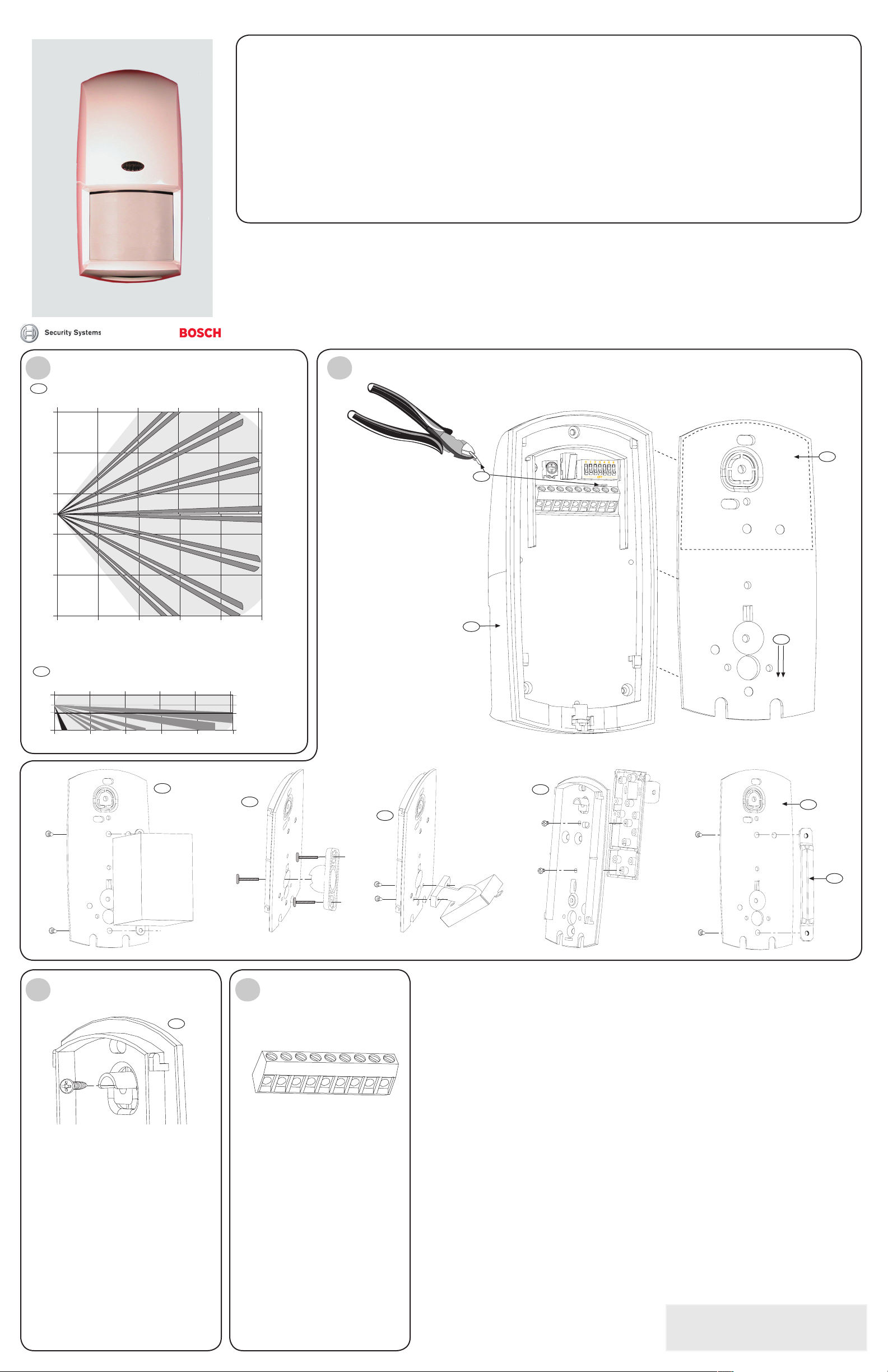
Coverage Patterns
Microwave coverage
PIR coverage
Look-down zone
Note: When choosing the appropriate mounting height
for your application (particularly, when the terrain is not
level) the upper fi nger is the strongest and responds
more quickly to an intruder’s presence. Every fi nger
shown in the top view (3-1) has the same side view
(3-2) confi guration.
Mounting
1. Select a mounting location. Mount the sensor where an intruder is most likely to cross the coverage pattern.
2. Mount the detector 7 ft to 9 ft (2.1 m to 2.7 m) above the ground. Recommended: 7 ft (2.1 m)
Note: Mounting height recommendations are based on level surfaces. If the terrain is not level, adjust the
mounting height and detector angle to provide the best coverage.
3. Slide the mounting plate down (4-1) until you hear a click, and remove it from the cover.
4. Mount the mounting plate using one of these options:
Note: Do not remove the waterproof label from the mounting plate (4-2). Push the mounting screws or wiring
knockouts through the label as needed.
- Surface mount using a single-gang electrical box.
1. Install a single-gang electrical box at the detector location.
2. Attach the mounting plate (4-3) to the single-gang box with the appropriate screws.
- Surface mount without an electrical box.
1. Select an appropriate location.
2. Using the mounting plate (4-1) as a template, mark the location of the mounting screws and the wire run.
3. Attach the mounting plate (4-1) to the wall with the appropriate screws.
- Surface Mount using the supplied B335 Bracket or an optional bracket. Use the bracket’s instructions to
attach the bracket to the appropriate mounting surface.
- Attach the B335 Bracket to the mounting plate. (4-4).
- Attach the B328 Bracket to the mounting plate. (4-5).
- Attach the B338 Bracket to the mounting plate. (4-6).
- Pole Mount using the supplied bracket.
Note: Do not mount to fence posts that might sway in the wind.
- Attach the bracket (4-7) to the mounting plate (4-8) using the appropriate screws and mounting
holes.
- Two hose clamps (not supplied) large enough to fi t around the pole are recommended for fastening
the detector mounting plate to the pole.
Tamper Options
The unit has a built-in cover tamper that signals when
the detector unit (4-9) separates from the
mounting plate (4-1). The unit can also be installed so
the tamper signals if the entire unit is pulled away from
the surface on which it is mounted.
Note: The wall and cover tamper option are only
available when the unit is surface mounted. The cover
tamper is available with all mounting options.
Determine whether the tamper switch is to be used as
a cover tamper or a wall and cover tamper:
- Wall and cover tamper: Use the appropriate
screw to fasten the mounting plate tamper section
(5-1) to the wall.
- Cover tamper: Do not attach the mounting plate
tamper section (5-1) to the wall.
Terminal Label Function
1 (-) Input power: Use at least a
22 AWG (0.8 mm) wire pair
between the unit and the
power source.
2 (+)
3 NC Alarm relay
4C
5 T Tamper
6T
7 NC Timed alarm relay contacts
8 C
9NO
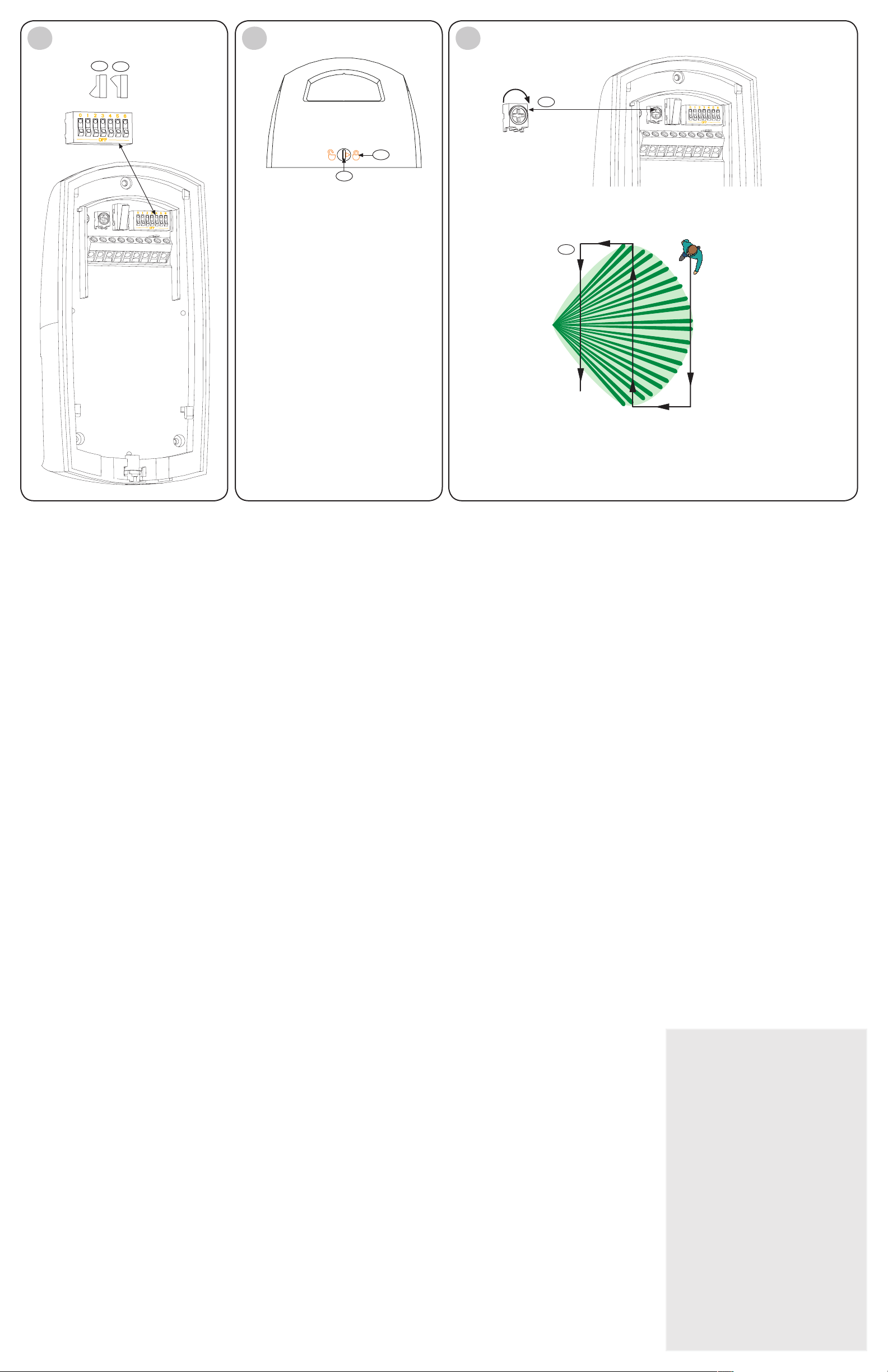
Wiring
DIP Switch Confi guration
(7-1) On
(7-2) Off
Switch Feature Description Switch Position
0 LED
Disable
Determines if the LED lights during
alarm situations.
Default factory setting: ON
ON: LED enabled
OFF: LED disabled
1 PIR
Sensitivity
Standard: Minimizes false alarms.
Tolerates environmental extremes
Intermediate: Use where an intruder
might cover only a small portion of the
protected area.
Tolerates normal environments.
Note: The detector is shipped in
Standard Mode.
ON: Standard
OFF: Intermediate
2 and 3 Timed
Relay
Outputs
Form “C,” unsupervised, timed relay
contact that transfers 1 sec after an
alarm. It follows a user-selectable
timer. The time expires at the time set
after the last alarm. It resets on each
new alarm.
SW2 SW3 Relay Activation Time
OFF OFF 2 sec
ON OFF 1 min
OFF ON 5 min
ON ON 10 min
4 AND/OR
Mode
Determines if the detector alarms
in the AND mode (when both
technologies simultaneously sense an
alarm condition) or in the OR mode
(when either the PIR or Microwave
technology senses an alarm state).
Note: The OR mode is not
recommended for most installations.
The OR mode provides faster
detection in some conditions. It
can also increase the likelihood of
nuisance alarms because the detector
activates the alarm relay based on
input from a single technology.
ON: AND Mode (recommended)
OFF: OR Mode, you must also cut the
jumper (4-10).
5 Day/Night
Mode
Note: If the LEDs are enabled (SW0),
then LED indications continue.
ON: With the control unit armed and this
switch ON, the unit does not trigger an
alarm during daylight.
OFF: With the control unit armed and this
switch OFF, the unit can trigger an alarm
day or night.
6 Not used
LED Display
LED Indicator Condition
Green
Steady PIR alarm
Flashing Microwave alarm
Red
Steady Dual alarm (both technologies)
Flashing Power-up
Attaching Detector to Mounting
Plate
1. When all wiring is connected to the detector but not
to the power supply and all the settings are made,
slide the detector unit (4-9) onto the mounting plate
(4-1) and down until it is fi rmly seated. Avoid
pinching the wires.
2. With a small fl at head screwdriver, turn the locking
cam (9-1) 180
o
to lock (9-2) the detector unit to the
mounting plate. Avoid excessive force.
Walk Test
Note: Ensure the detector is fastened to the mounting plate and all wiring is connected and powered before
beginning the Walk Test.
Note: Ensure the LED Disable (SW0) is on (refer to Section 7 DIP Switch Confi guration).
Note: To avoid false alarms, set the microwave range (10-1) to its minimum setting before starting the Walk Test.
Microwave coverage
PIR coverage
1. Wait at least 2 minutes after power up to start the
Walk Test.
The LED fl ashes red until the detector stabilizes and
no movement is detected for 2 seconds.
2. Watch the LED as you walk towards the edge of the
pattern (10-2). The LED lights at the outside edge of
the coverage range.
3. Repeat Step 3 from different directions until you
adequately verify the coverage pattern.
The green LED lights, identifying the PIR pattern
edge.
The green LED fl ashes, identifying the microwave
pattern edge.
4. Repeat Step 3 from the opposite side.
5. If the required range is not achieved, increase the
microwave adjustment (10-1) by turning it clockwise
slightly.
6. Repeat the walk test and adjustments until you
reach the farthest edge of coverage needed.
Page 4

Opmerking: Zorg ervoor dat de detector op de bevestigingsplaat wordt vastgezet en dat alle bedrading is
aangesloten en voorzien van stroom alvorens met de looptest te beginnen.
Opmerking: Zorg ervoor dat de LED-deactivatie (SW0)
aan staat (raadpleeg hoofdstuk 7: DIP-schakelwerking).
Opmerking: Zet, voordat u de looptest start, het
microgolfbereik (10-1) in op de minimuminstelling om
vals alarm te voorkomen.
Microgolfbereik
PIR-bereik
1. Wacht na inschakeling tenminste 2 minuten
voordat u met de looptest begint. De rode LED
knippert totdat de detector gestabiliseerd is en
wanneer gedurende 2 seconden geen beweging
waargenomen is.
2. Kijk naar de LED wanneer u naar de rand van het
gezichtsveld loopt (10-2). De LED aan de buitenkant
van het gezichtsveld licht op.
3. Herhaal stap 3 vanuit diverse richtingen totdat u het
gezichtsveld voldoende getest heeft.
De groene LED, die de rand van het PIRgezichtsveld identifi ceert, licht op.
Het groene LED knippert, waarmee het microgolf
grensbereik is bepaald.
4. Herhaal stap 3 vanaf de andere kant.
5. Als het benodigde bereik niet wordt gehaald,
vergroot dan de microgolfi nstelling (10-1) door het
enigszins met de klok mee te draaien.
6. Herhaal de looptest en aanpassingen totdat u de
verste grens van de vereiste instelling bereikt hebt.
Bosch Security Systems
130 Perinton Parkway
Fairport, NY 14450-9199
www.boschsecuritysystems.com
© 2005 Bosch Security Systems
48674H
Pagina 4 von 10
OD850
Gebruiksaanwijzing voor de installatie
van de passieve infrarooddetector
voor buitengebruik/microgolf
inbraakdetector
1
2
3
4
5
6
7
8
9
10
Technische beschrijving
Afmetingen: 16,5 cm x 8,25 cm x
5,7 cm
Ingangsvermogen: 10 VDC t/m 15 VDC
op 22mA stand-by.
Maximale stroom 62
mA. Maak alleen gebruik
van een Listed limited
vermogensbron.
Stand-by vermogen: Geen interne stand-by
batterij.
Alarm relais: Form “A” Normaal
gesloten (NG),
gecontroleerd
alarmcontact opent
tijdens alarm. Form “C”
ongecontroleerd, getimed
relaiscontact gaat over
bij alarm en houdt een
programmeerbare timer
aan.
Contact
classifi caties:
3 W, 125mA maximaal,
25VDC maximaal voor
DC resistente ladingen;
en beschermd door een
4,7 Ω, ½ W weerstand in
de normale “C” poot van
het relais.
Opmerking: Niet
gebruiken met capacitieve
of inductieve ladingen.
Temperatuursgebied: Het temperatuursgebied
voor alle installaties is
-35°C to +60°C.
Microgolf-frequentie: OD850-F1: 10.525 GHz
OD850-F2: 10.588 GHz
Bereik: 15 m x 15 m
Knoei-optie: NG (met geplaatste kap).
Contacten berekend op
125 mA maximaal, 25
VDC maximaal. Verbindt
knoeischakelaarcircuit
met een 24-uurs
beschermingscircuit.
IP-classifi catie: 54
Opties: B335 discrete draaibare
bevestigingsarm
(meegeleverd),
B328 draaibare
bevestigingsarm, B338
plafondarm, staafarm
(meegeleverd).
Opmerking: Wanneer de
detector op deze armen
niet goed wordt uitgelijnd,
dan kan het bereik van
de detector verkleind
en de grootte van het
onwaarneembare gebied
vergroot worden.
Installeer de detector niet waar de PIR of microgolf in
constant alarm verkeert (LED aan). De LED staat uit bij
correcte installatie.
Niet richten op verkeer.
Niet installeren waar hangende informatieborden,
bomen of andere objecten door de wind binnen het
gezichtsveld bewogen kunnen worden, of waar dieren in
het wild binnen het gezichtsveld kunnen betreden.
Bevestig de detector op een stevige en trilvrije
ondergrond.
Waarschuwing!
- Sluit elektriciteit alleen aan wanneer alle
aansluitingen zijn gemaakt en geïnspecteerd.
Overvloedige bedrading niet in de detector oprollen.
- Sluit geen enkele terminal aan op een
vermogensbron die meer dan 25 VDC levert.
SELV
In sommige landen dient het relais alleen aangesloten
te worden op een Safety Extra-Low Voltage (SELV)
circuit.
Aandachtspunten voor
installatie
Microgolfbereik
PIR-bereik
Benedenzichtgebied
Opmerking: Bij het bepalen van de geschikte
bevestigingshoogte voor uw systeem (vooral wanneer
het terrein niet effen is) is het bovenste onderdeel het
sterkst en reageert het sneller op de aanwezigheid van
een indringer. Ieder onderdeel dat in het bovenaanzicht
(3-1) is afgebeeld heeft dezelfde zijaanzicht (3-2)
confi guratie.
Gezichtsvelden
1. Selecteer een bevestigingsplek. Bevestig de sensor waar een indringer het meest waarschijnlijk het
gezichtsveld zou kunnen doorkruisen.
2. Bevestig de detector 2,10 tot 2,70 meter boven de vloer. Aanbevolen: 2,1 m
Opmerking: Aanbevolen bevestigingshoogten zijn gebaseerd op effen oppervlakten. Stel de bevestigingshoogte
en detectorhoek af om het beste bereik te verkrijgen wanneer het terrein niet vlak is.
3. Schuif de bevestigingsplaat naar beneden (4-1) totdat u een klik hoort en verwijder het van de kap.
4. Bevestig de bevestigingsplaat volgens één van de volgende opties:
Opmerking: Het waterproofl abel niet van de bevestigingsplaat verwijderen (4-2). Duw de bevestigingsschroeven
door het label heen indien nodig.
- Bevestiging met een enkele elektrische doos.
1. Installeer een enkele elektrische doos op de plaats van de detector.
2. Bevestig de bevestigingsplaat (4-3) met de geschikte schroeven op de enkele elektrische doos.
- Bevestiging zonder een elektrische doos.
1. Selecteer een geschikte bevestigingsplaats.
2. Gebruik de bevestigingsplaat (4-1) als mal om de plaats van de bevestigingsschroeven en de
bedradingen te markeren.
3. Bevestig de bevestigingsplaat (4-1) aan de muur met de geschikte schroeven.
- Bevestigen met behulp van de meegeleverde B335-arm of een optionele arm. Gebruik de instructies van de
arm om de bevestigingsarm op het juiste bevestigingsoppervlak te bevestigen.
- Bevestig de B335-arm op de bevestigingsplaat. (4-4).
- Bevestig de B328-arm op de bevestigingsplaat. (4-5).
- Bevestig de B338-arm op de bevestigingsplaat. (4-6).
- Bevestig op de staaf met behulp van de meegeleverde arm.
Opmerking: Niet op hekpalen plaatsen die in de wind kunnen bewegen.
- Bevestig de arm (4-7) op de bevestigingsplaat (4-8) met behulp van de daarvoor bestemde schroeven
en bevestigingsgaten.
- Twee slangklemmen (niet meegeleverd) die groot genoeg zijn en rond de staaf passen worden
aanbevolen om de bevestigingsplaat van de detector op de staaf te bevestigen.
Bevestiging
De unit heeft een ingebouwde knoeidekking die een
signaal afgeeft wanneer de detector unit (4-9) van
de bevestigingsplaat (4-1) wordt gescheiden. De unit
kan ook zo geïnstalleerd worden dat de knoei-optie
een signaal afgeeft wanneer de gehele unit van het
oppervlak waarop deze is bevestigd wordt getrokken.
Opmerking: De knoei-opties die van toepassing zijn
op de muur en de kap zijn alleen beschikbaar wanneer
de unit op een oppervlak is bevestigd. De knoei-optie
die van toepassing is op de kap is beschikbaar met alle
bevestigingsmogelijkheden.
Bepaal of de knoeischakelaar ingeschakeld moet
worden voor de knoei-optie voor de kap, of voor de
muur en de kap.
- Knoei-opties voor de muur en de kap: Gebruik
de daarvoor bestemde schroef om de
bevestigingsplaat van de knoei-sectie (5-1) tegen
de muur te bevestigen.
- Knoei-optie voor de kap: Bevestig de
bevestigingsplaat van de knoei-sectie (5-1) niet
tegen de muur.
Knoei-opties
Terminal Label Functie
1 (-) Ingangsvermogen: Gebruik
tenminste een 22 AWG (0,8
mm) aderpaar tussen de unit
en de energiebron.
2 (+)
3 NG Alarmrelais
4G
5 T Knoei-optie
6 T
7 NG Getimede
alarmrelaiscontacten
8 G
9NO
Bedrading
(7-1) Aan
(7-2) Uit
Schakelaar Functie Omschrijving Schakelaarpositie
0 LED
gedeactiveerd
Bepaalt of de LED oplicht tijdens
alarmsituaties.
Standaard fabrieksinstelling AAN
AAN: LED geactiveerd
UIT: LED gedeactiveerd
1 PIR
gevoeligheid
Standaard: Minimaliseert valse
alarmen. Tolereert omgevingsextremen.
Medium: Te gebruiken waar een
indringer zich over slechts een klein deel
van het bewaakte gebied zou kunnen
verplaatsten.
Tolereert normale omstandigheden.
Opmerking: De detector wordt in de
standaardmodus aangeleverd.
AAN: Standaard
UIT: Medium
2 en 3 Getimede
relais-outputs
Form “C” ongecontroleerd, getimed
relais contact dat 1 seconde na het
alarm overgaat. Het maakt gebruik
van een timer die door de gebruiker
geselecteerd kan worden. De tijd loopt
af op de tijd die na het laatste alarm is
ingesteld. Na ieder nieuw alarm vervalt
de ingestelde tijd.
SW2 SW3 Relais
activatietijd
UIT UIT 2 sec
AAN UIT 1 min
UIT AAN 5 min
AAN AAN 10 min
4 EN/OF
modus
Bepaalt of de detector alarm
geeft in de EN-modus (wanneer
beide technologieën tegelijk een
alarmsituatie waarnemen) of in de
OF-modus (wanneer de PIR of de
microgolftechnologie een alarmsituatie
waarneemt).
Opmerking: De OF-modus wordt voor
het merendeel van de installaties niet
aanbevolen. De OF-modus verschaft in
sommige omstandigheden een snellere
detectie. Het kan de kans op loos
alarm vergroten omdat de detector het
alarmrelais activeert op basis van de
input van één technologie.
AAN: EN-modus
(aanbevolen)
UIT: OF-modus, u moet ook
de geleidingsbrug (4-10)
scheiden.
5 Dag/
nachtmodus
Opmerking: Indien de LED’s
geactiveerd zijn (SW0), zullen de LEDindicaties voortduren.
AAN: Wanneer de controleunit is geactiveerd en deze
schakelaar staat AAN, dan zal
de unit gedurende daglicht
geen alarm geven.
UIT: Wanneer de controleunit is geactiveerd en deze
schakelaar staat UIT, dan kan
de unit gedurende de dag en
de nacht alarm geven.
6 Niet gebruikt
DIP-schakelconfi guratie
LED-indicator Conditie
Groen
Constant PIR-alarm
Knipperend Microgolf-alarm
Rood
Constant
Tweevoudig alarm
(beide technologieën)
Knipperend Opstarten
LED-display
1. Wanneer alle bedrading op de detector is
aangesloten, maar niet op de voedingsbron, en alle
instellingen zijn voltooid, schuif dan de detectorunit
(4-9) op de bevestigingsplaat (4-1) en naar beneden
totdat hij stevig op zijn plaats zit. Zorg dat de
bedrading niet beklemd zit.
2. Draai het sluitmechanisme (9-1) met een
platkopschroevendraaier 180
o
om de detector op de
bevestigingsplaat vast te zetten (9-2). Gebruik geen
overdadige kracht.
Het bevestigen van de detector
aan de bevestigingsplaat
Looptest
Page 5

Bosch Security Systems
130 Perinton Parkway
Fairport, NY 14450-9199
www.boschsecuritysystems.com
© 2005 Bosch Security Systems
48674H
Page 5 sur 10
1
2
3
4
5
6
7
8
9
10
Caractéristiques techniques
Dimensions : 16,5 cm x 8,25 cm x 5,7 cm
(6,5 po. x 3,25 po. x 2,25 po.)
Alimentation : De 10 Vcc à 15 Vcc à 22mA
en veille. Consommation
maximum de 62 mA.
Alimentation de
secours :
Pas de batterie de secours
interne.
Relais d’alarme : Form « A » Contact d’alarme
contrôlé normalement
fermé (NF) s’ouvre en cas
d’alarme. Form « C » non
contrôlée, contact de relais
temporisé est transféré en cas
d’alarme et suit une minuterie
programmable à l’installation.
Capacité des
contacts :
3 W, 125 mA maximum,
25 Vcc maximum pour
charges résistives en courant
continu et protégées par une
résistance de 4,7 Ω et ½ W
sur le commun « C » du relais.
Remarque : Ne pas utiliser
avec des charges capacitives
ou inductives.
Température : Les températures admises
vont de -35°C à +60°C (-31°F
à +140°F) pour toutes les
installations.
Hyperfréquence : OD850-F1: 10.525 GHz
OD850-F2: 10.588 GHz
Portée : 15 m par 15 m (50 pi par
50 pi)
Autoprotection : Normalement fermé (avec
capot en place). Contacts
calibrés à 125 mA maximum,
25 Vcc maximum. Connecter
le circuit d’autoprotection
à un circuit de protection
fonctionnant 24h/24.
IP Rating : 54
Options : Support sur pivot plat B335
(fourni), support sur pivot
B328, support sur rotule pour
installation au plafond B338,
support pour installation sur
poteau (fourni).
Remarque : Un défaut
d’alignement du détecteur
sur ces supports peut réduire
le champ de détection et
augmenter la zone d’angle
mort.
Conformité : Ce dispositif est conforme à la
section 15 du règlement de la
FCC et aux directives de RSS210 de « Industry and Science
Canada ». Le fonctionnement
est soumis à deux conditions :
1. Ce dispositif n’entraîne pas
d’interférence préjudiciable.
2. Ce dispositif accepte tout
type d’interférence, y
compris les interférences
susceptibles d’entraîner un
dysfonctionnement.
Toute modifi cation que Bosch
Security Systems n’aurait pas
expressément approuvée
peut annuler la capacité
de l’utilisateur à utiliser le
dispositif.
Ne jamais installer le détecteur à un endroit où l’IRP ou
hyperfréquence est constamment activé (voyant LED
allumé). Si le détecteur est correctement installé, le
voyant LED est éteint.
Ne pas diriger vers des zones de mouvement.
Eviter d’installer à un endroit où des panneaux
suspendus, des arbres ou d’autres objets sont
susceptibles d’être agités par le vent dans le champ de
détection et où des animaux peuvent se déplacer dans
le champ de détection.
La surface de montage doit être solide et exempte de
vibrations.
Attention !
- Ne mettre l’appareil sous tension qu’une fois tous
les branchements effectués et vérifi és. Ne pas
accumuler l’excès de fi l à l’intérieur du détecteur.
- Ne brancher aucune borne à une source
d’alimentation fournissant plus de 25 Vcc.
SELV
Dans certains pays, le relais doit être connecté à
un circuit de très basse tension de sécurité (SELV)
uniquement.
Conseils relatifs à l’installation
Portée hyperfréquence
Portée IRP
Zone de détection vers le bas
Remarque : Lorsque vous choisissez la hauteur de
montage appropriée pour votre utilisation (en particulier
lorsque le terrain n’est pas plat), le doigt supérieur est
le plus fort et réagit plus rapidement à une intrusion.
Chaque doigt illustré sur la vue de dessus (3-1) a la
même confi guration sur la vue de côté (3-2).
Diagrammes illustrant le
champ de détection
1. Choisissez l’emplacement où vous installerez le détecteur. Installez-le à un endroit où le champ de détection
sera presque inévitablement traversé en cas d’intrusion.
2. Installez le détecteur à au moins 2,1 m du sol (maximum 2,7 m). Hauteur recommandée : 2,1 m (7 pi)
Remarque : Les recommandations de hauteur se basent sur des surfaces planes. Si le terrain n’est pas plat,
ajustez la hauteur de montage et l’angle du détecteur pour assurer la meilleure couverture.
3. Faites glisser la plaque de montage vers le bas (4-1) jusqu’à ce que vous entendiez un clic et retirez-la du
capot.
4. Fixez la plaque de montage en procédant de l’une des manières suivantes :
Remarque : Ne retirez pas l’étiquette indiquant l’étanchéité à l’eau de la plaque de montage (4-2). Faites passer
les vis de montage ou les orifi ces pré-découpés à travers l’étiquette si besoin est.
- Montage sur surface plane à l’aide d’un coffret électrique à un seul interrupteur.
1. Installez un coffret électrique à un seul interrupteur à l’emplacement du détecteur.
2. Fixez la plaque de montage (4-3) au coffret à un seul interrupteur à l’aide des vis adéquates.
- Montage sur surface plane sans coffret électrique.
1. Choisissez un emplacement de montage.
2. En vous guidant avec la plaque de montage (4-1), marquez l’emplacement des vis de montage et du
passage des fi ls.
3. Fixez la plaque de montage (4-1) au mur à l’aide des vis adéquates.
- Montage sur surface plane à l’aide du support B335 fourni ou d’un support en option. Utilisez les instructions
fournies avec le support pour fi xer ce dernier à la surface de montage adéquate.
- Fixez le support B335 à la plaque de montage. (4-4).
- Fixez le support B328 à la plaque de montage. (4-5).
- Fixez le support B338 à la plaque de montage. (4-6).
- Fixez au poteau en utilisant le support fourni.
Remarque : Ne montez pas l’appareil sur un piquet de clôture qui risque de se balancer avec le vent.
- Fixez le support (4-7) à la plaque de montage (4-8) à l’aide des vis et des trous de montage
appropriés.
- Il est recommandé d’utiliser deux colliers de serrage pour tuyaux (non fournis) assez grands pour être
placés sur le poteau pour y fi xer fermement la plaque de montage du détecteur.
Installation
Options d’autoprotection
L’appareil comporte un capot autoprotection intégré
qui donne une alerte si le détecteur (4-9) est séparé de
la plaque de montage (4-1). L’appareil peut aussi être
installé de sorte que l’autoprotection signale le retrait de
toute l’unité de la surface sur laquelle elle est installée.
Remarque : L’option d’autoprotection mur et capot n’est
disponible que si l’unité est installée sur une surface
plane. L’autoprotection capot est disponible dans toutes
les options de montage.
Déterminez si l’interrupteur de sécurité doit être utilisé
pour une autoprotection capot ou une autoprotection
mur et capot :
- Autoprotection mur et capot : Utilisez la vis
adéquate pour fi xer la partie autoprotection de la
plaque de montage (5-1) au mur.
- Autoprotection capot : Ne fi xez pas la partie
autoprotection de la plaque de montage (5-1) au
mur.
Câblage
Borne Indication Fonction
1 (-) IAlimentation : Utilisez au
moins une paire de fi ls de
22 AWG (0,8 mm) entre
l’appareil et la source
d’alimentation.
2(+)
3 NF Relais d’alarme
4C
5 T Autoprotection
6T
7 NF Contacts de relais d’alarme
temporisés
8 C
9NO
(7-1) On
(7-2) Off
Confi guration des commutateurs DIP
Commutateur Fonction Description Position de l’interrupteur
0 Désactivation
des voyants
LED
Détermine si les voyants LED s’allument
en cas d’alarme.Paramètre d’usine par
défaut : ON
ON : Voyant LED activé
OFF : Voyant LED désactivé
1 Sensibilité
IRP
Standard : Minimise les fausses
alarmes et tolère les environnements
extrêmes
Intermédiaire : Utilisé lorsque l’intrusion
ne couvre qu’une petite partie de la zone
protégée.
Tolère les environnements normaux.
Remarque : Le détecteur est livré en
mode standard.
ON : Standard
OFF : Intermédiaire
2 et 3 Sorties
du relais
temporisé
Form « C », contact de relais temporisé
non contrôlé qui est transféré 1 sec
après une alarme. Suit une minuterie
sélectionnée par l’utilisateur. La durée
expire au moment défi ni après la
dernière alarme. Réinitialisation après
chaque nouvelle alarme.
SW2 SW3 Durée
d’activation
du relais
OFF OFF 2 sec
ON OFF 1 min
OFF ON 5 min
ON ON 10 min
4 Mode
AND/OR
Détermine si le détecteur signale une
alarme en mode AND (lorsque les deux
technologies détectent simultanément
une perturbation) ou en mode OR
(lorsqu’une des deux technologies,
IRP ou hyperfréquence, détecte une
perturbation).
Remarque : Le mode OR n’est pas
recommandé pour la plupart des
installations. Le mode OR offre une
détection plus rapide dans certaines
conditions. Il peut aussi accroître les
occurrences d’alarmes de nuisance car
le détecteur active le relais d’alarme sur
la base d’une seule des technologies.
ON : Mode AND
(recommandé)
OFF : Mode OR, vous devez
aussi fermer le cavalier (4-10)
5 Mode
Jour/Nuit
Remarque : Si les voyants LED sont
activés (SW0), ils continuent à indiquer
les divers états.
ON : Lorsque l’unité de
commande est armée et ce
commutateur est en position
ON, l’unité ne déclenche pas
d’alarme lorsqu’il fait jour.
OFF : Lorsque l’unité de
commande est armée et ce
commutateur est en position
OFF, l’unité déclenche des
alarmes le jour comme la nuit.
6 Non utilisé
Ecran LED
Indicateur LED Etat
Vert
Continu Alarme IRP
Clignotement Alarme hyperfréquence
Rouge
Continu
Alarme double
(les deux technologies)
Clignotement Alimentation initiale
1. Lorsque tous les fi ls sont branchés au détecteur
(mais pas au bloc d’alimentation) et que tous les
réglages sont effectués, faites glisser le détecteur
(4-9) dans la plaque de montage (4-1) jusqu’à ce
qu’elle y soit bien placée. Evitez de coincer les fi ls.
2. A l’aide d’un tournevis à tête plate, tournez la came
de verrouillage (9-1) de 180
o
pour verrouiller (9-2) le
détecteur sur la plaque de montage. Ne forcez pas
trop.
Fixation du détecteur sur la
plaque de montage
Remarque : Assurez-vous que le détecteur est fi xé à la
plaque de montage et que tous les fi ls sont branchés et
alimentés avant de commencer le test de marche.
Remarque : Vérifi ez que le commutateur de
désactivation des voyants LED (SW0) est ouvert
(consultez la Section 7, Confi guration des
commutateurs DIP).
Remarque : Afi n d’éviter les fausses alarmes, réglez
la portée hyperfréquence (10-1) au minimum avant
d’effectuer le test de marche.
Portée hyperfréquence
Portée IRP
1. Pour commencer le test de marche, patientez au
moins deux minutes après la mise sous tension.
Le voyant LED clignote en rouge, puis le détecteur
se stabilise quand aucun mouvement n’est détecté
durant 2 secondes.
Test de marche
2. Approchez-vous de la limite du champ de détection
tout en observant le voyant LED (10-2). Le voyant
LED s’allume sur le bord extérieur du champ de
détection.
3. Recommencez l’étape 3 en procédant dans
différentes directions jusqu’à ce que vous ayez bien
vérifi é le champ de détection.
Le voyant LED vert s’allume, identifi ant le bord du
champ IRP.
Le voyant LED vert clignote, identifi ant le bord du
champ d’hyperfréquence.
4. Répétez l’étape 3 en commençant de l’autre côté.
5. Si la portée requise n’est pas obtenue, augmentez
le réglage de l’hyperfréquence (10-1) en tournant
légèrement dans le sens des aiguilles d’une montre.
6. Recommencez le test de marche et ajustez les
réglages jusqu’à ce que vous obteniez la portée
maximale nécessaire.
Notice d’installation
du détecteur à infrarouge passif/détecteur
d’intrusion à hyperfréquence
OD850 Extérieur
Page 6

Bosch Security Systems
130 Perinton Parkway
Fairport, NY 14450-9199
www.boschsecuritysystems.com
© 2005 Bosch Security Systems
48674H
Seite 6 von 10
1
2
3
4
5
6
OD850 AUSSENMELDER
Passiver Infrarotmelder/Mikrowelleneinbr
uchsmelder
Installationsanleitungen
Technische Daten
Abmessungen: 16,5 cm x 8,25 cm x
5,7 cm
Eingangsleistung: V DC bis 15 V
DC bei max. 22
mA (Ruhestrom).
Höchststrom 62
mA. Es darf nur eine
zugelassene begrenzte
Stromquelle verwendet
werden.
Notstrom: Keine interne
Notstrombatterie.
Alarmrelais: Form A-Öffner,
überwachter
Alarmkontakt
öffnet bei Alarm.
Unüberwachter Form
C-Zeitrelaiskontakt
überträgt bei Alarm
und ist von einem
vom Installateur
programmierbaren
Zeitschalter abhängig.
KontaktNennleistungen:
3 W, 125 mA, 25 V DC
(max.) für ohmsche
Belastungen, Schutz
mittels 4,7 Ω, 1/2
W-Widerstand an
gemeinsamer „C“Leitung des Relais.
Hinweis: Nicht mit
kapazitiven oder
induktiven Lasten
verwenden.
Temperaturbereich: Der Temperaturbereich
für alle zugelassenen
Installationen beträgt
-35°C bis +60°C.
Mikrowellenfrequenz: OD850-F1: 10.525 GHz
OD850-F2: 10.588 GHz
Überwachungsbereich: 15 m x 15 m
Sabotageschutz: Öffner (bei
geschlossener
Abdeckung). KontaktNennleistung bei
max. 125 mA, 25 V
DC. Schließen Sie
den SabotageschutzStromkreis an
eine ständig aktive
Schutzschaltung an.
Gehäuse-schutz
(IP-Code):
54
Optionen: Schwenkbare
B335-Halterung
in Flachbauweise
(im Lieferumfang
enthalten),
schwenkbare B328Halterung, B338Deckenhalterung,
Masthalterung
(im Lieferumfang
enthalten).Hinweis: Eine
falsche Ausrichtung
des Melders in diesen
Halterungen kann
zur Reduzierung der
Reichweite des Melders
und zur Vergrößerung
des unbewachten
Bereichs führen.
Der Melder darf unter keinen Umständen installiert
werden, wenn sich das PIR- oder Mikrowellensystem
ständig im Alarmzustand befi ndet (LED eingeschaltet).
Bei ordnungsgemäßer Installation ist die LED
ausgeschaltet.
Nicht auf Verkehrsbereiche richten.
Nicht an Stellen installieren, an denen sich Hängeschilder,
Bäume oder andere Objekte, die sich im Wind bewegen
können, im Überwachungsbereich befi nden oder an
denen Wildtiere den Überwachungsbereich durchqueren
können.
Die Montageoberfl äche muss fest und vibrationsfrei sein.
Achtung!
- Strom erst anlegen, wenn alle Anschlüsse
vorgenommen und überprüft wurden. Drähte nicht im
Melder aufwickeln.
- Keine Klemme darf an eine Stromquelle mit über 25
V DC angeschlossen werden.
SELV
In einigen Ländern darf das Relais nur an einen SELVStromkreis (Sicherheits-Kleinspannungs-Stromkreis)
angeschlossen werden.
Hinweise für die Installation
Mikrowellenüberwachung
PIR-Überwachung
Unterkriechschutzzone
Hinweis: Bei der Auswahl der richtigen Montagehöhe für
Ihre Anwendung (insbesondere auf unebenem Gelände)
ist der obere Zeiger am stärksten und reagiert schneller
auf einen Eindringling. Jeder Zeiger in der Draufsicht
(3-1) hat die gleiche Seitenansicht-Konfi guration (3-2).
Überwachungsbereiche
1. Wählen Sie einen Montageort. Installieren Sie den Sensor an einer Stelle, an der eine eindringende Person
höchstwahrscheinlich den Überwachungsbereich durchqueren würde.
2. Montieren Sie den Melder 2,1 m bis 2,7 m über dem Boden. Empfohlene Montagehöhe: 2,1 m
Hinweis: Empfehlungen für die Montagehöhe gelten für ebene Grundfl ächen. Bei unebenem Gelände müssen
Montagehöhe und Melderwinkel so verstellt werden, dass ein optimaler Überwachungsbereich gewährleistet ist.
3. Verschieben Sie die Montageplatte (4-1) nach unten, bis es klickt und nehmen Sie sie von der Abdeckung
ab.
4. Die folgenden Montageoptionen stehen für den Montageplatte zur Verfügung:
Hinweis: Nehmen Sie nicht das Schild mit dem Hinaus auf die Wasserundurchlässigkeit von der Montageplatte
(4-2) ab. Schieben Sie bei Bedarf die Montageschrauben oder vorbereiteten Drahtöffnungen durch das Schild.
- Oberfl ächenmontage mit einer elektrischen Einfachdose.
1. Installieren Sie eine elektrische Einfachdose am Melderstandort.
2. Bringen Sie die Montageplatte (4-3) mit den entsprechenden Schrauben an die Einfachdose an.
- Oberfl ächenmontage ohne Elektrodose.
1. Wählen Sie eine geeignet Stelle.
2. Benutzen Sie die Montageplatte (4-1) als Schablone und markieren Sie die Lage der Montageschrauben
und den Drahtverlauf.
3. Bringen Sie die Montageplatte (4-1) mit den entsprechenden Schrauben an der Wand an.
- Oberfl ächenmontage mit der mitgelieferten B335-Halterung oder einer optionalen Halterung. Bringen Sie die
Halterung gemäß den Anleitungen für die Halterung an einer entsprechenden Montageoberfl äche an.
- Montieren Sie die B335-Halterung an die Montageplatte. (4-4).
- Montieren Sie die B328-Halterung an die Montageplatte. (4-5).
- Montieren Sie die B338-Halterung an die Montageplatte. (4-6).
- Mastbefestigung mit mitgelieferter Halterung.
Hinweis: Nicht an Zaunpfähle montieren, die im Wind schwanken können.
- Befestigen Sie die Halterung (4-7) mit den entsprechenden Schrauben und Montagelöchern an der
Montageplatte (4-8).
- Verwenden Sie zwei Schlauchklemmen (nicht im Lieferumfang enthalten), die um den Mast passen,
um die Meldermontageplatte am Mast zu befestigen.
Montage
Das Gerät hat einen eingebauten Deckelsabotageschutz,
der signalisiert, wenn die Meldereinheit (4-9) von der
Montageplatte (4-1) abgenommen wird. Das Gerät kann
auch so installiert werden, dass der Sabotageschutz
ein Signal gibt, wenn das gesamte Gerät von der
Montageoberfl äche gezogen wird.
Hinweis: Die Optionen Wand- und Deckelmontageschutz
stehen nur zur Verfügung, wenn das Gerät auf einer
Oberfl äche montiert ist. Der Deckelmontageschutz steht
für alle Montageoptionen zur Verfügung.
Stellen Sie fest, ob der Sabotageschutzschalter
als Deckelsabotageschutz bzw. als Wand- und
Deckelsabotageschutz zu verwenden ist:
- Wand- und Deckelsabotageschutz: Befestigen
Sie den Sabotageschutzabschnitt (5-1) der
Montageplatte mit der entsprechenden Schraube an
der Wand.
- Deckelsabotageschutz: Befestigen Sie den
Sabotageschutzabschnitt (5-1) der Montageplatte
nicht an der Wand.
Sabotageschutzoptionen
Verdrahtung
Klemme Etikett Funktion
1 (-) Eingangsleistung: Wenigstens
ein 0,8 mm dickes Drahtpaar
zwischen dem Gerät und der
Stromquelle verwenden.
2 (+)
3 NC Alarmrelais
4 C
5 T Sabotageschutz
6T
7 NC Alramrelaiskontakte mit
Zeitschalter
8 C
9NO
7
(7-1) On
(7-2) Off
Schalter Funktion Beschreibung Schalterposition
0 LED aus Legt fest, ob die LED-Leuchten unter
Alarmbedingungen aufl euchten.
Vorgabeeinstellung ab Werk: ON (EIN)
ON (EIN): LED ein
OFF (AUS): LED aus
1 PIR-
Empfi ndlichkeit
Standard: Möglichst wenige Fehlalarme.
Umgebungsextreme werden toleriert.
Mittlere Einstellung: Verwenden, wenn
ein Eindringling unter Umständen nur einen
kleinen Teil des Überwachungsbereichs
abdeckt.
Normale Umgebungen werden toleriert.
Hinweis: Der Melder wird im Standardmodus
versandt.
ON (EIN): Standard
OFF (AUS): Mittlere Einstellung
2 und 3 Relaisausgang
mit Zeitschalter
Form “C,” unsupervised, timed relay contact
that transfers 1 sec after an alarm. It follows a
user-selectable timer. The time expires at the
time set after the last alarm. It resets on each
new alarm.
SW2 SW3 Relaisaktivi-
rungszeit
AUS
(OFF)
AUS
(OFF)
2 Sek
EIN
(ON)
AUS
(OFF)
1 Min
AUS
(OFF)
EIN
(ON)
5 Min
EIN
(ON)
EIN
(ON)
10 Min
4 AND/OR-
Modus
(UND/ODER)
Legt fest, ob der Melder Alarme im ANDModus (beide Überwachungsuntersysteme
erfassen gleichzeitig einen Alarmzustand)
oder im OR-Modus (entweder das PIR- oder
das Mikrowellenuntersystem erfassen einen
Alarmzustand) meldet.
Hinweis: Der OR-Modus wird für die meisten
Installationen nicht empfohlen. Unter einigen
Umständen bietet der OR-Modus eine
schnellere Erkennung. Außerdem erhöht sich
die Wahrscheinlichkeit für Fehlalarme, weil die
Aktivierung des Alarmrelais auf der Eingabe
eines Untersystems beruht.
ON (EIN): AND-Modus
(empfohlen)
OFF (AUS): OR-Modus, Sie
müssen auch die Drahtbrücke (4-
10) durchtrennen.
5 Day/Night-
Modus
(Tag/Nacht)
Hinweis: Wenn
LED-Anzeigen bleiben eingeschaltet, wenn die
LEDs aktiviert sind (SW0).
ON (EIN): Mit dem
scharfgeschalteten Kontrollgerät
und diesem Schalter in ONStellung (EIN), wird bei Tageslicht
kein Alarm ausgelöst.
OFF (AUS): Mit dem
scharfgeschalteten Kontrollgerät
und diesem Schalter in OFFStellung (AUS), kann Tag und
Nacht ein Alarm ausgelöst
werden.
6 Nicht
verwendet
DIP-Schalter-Konfi guration
8
LED-Anzeige
LED-Indikator Bedingung
Grün
Ständig PIR-Alarm
Blinken Mikrowellenalarm
Rot
Ständig
Doppelalarm (beide
Methoden)
Blinken Starten
9
1. Wenn alle Drähte am Melder angeschlossen und
nicht am Netzteil angeschlossen sind und alle
Einstellungen vorgenommen wurden, schieben Sie
die Meldereinheit (4-9) auf die Montageplatte (4-1)
nach unten, bis sie fest sitzt. Die Drähte dürfen dabei
nicht eingeklemmt werden.
2. Mit einem kleinen Senkkopf-Schraubendreher wird
die Sperrnocke (9-1) um 180° gedreht, um die
Meldereinheit mit der Montageplatte zu verriegeln
(9-2). Wenden Sie dabei keine übermäßige Kraft an.
Montage des Melders an
Montageplatte
10
Hinweis: Stellen Sie sicher, dass der Melder an der
Montageplatte befestigt ist, alle Drähte angeschlossen
sind, und das Gerät eingeschaltet ist, bevor Sie mit dem
Gehtest beginnen.
Hinweis: Stellen Sie sicher, dass LED Aus (SW0) auf ein
steht (siehe Abschnitt 7 DIP-Schalter-Konfi guration).
Hinweis: Setzen Sie vor Beginn des Gehtests den
Mikrowellenbereich (10-1) auf seine niedrigste
Einstellung, um Fehlalarme zu vermeiden.
Mikrowellenüberwachung
PIR-Überwachung
1. Warten Sie mindestens 2 Minuten nach dem
Einschalten, bevor Sie mit dem Gehtest beginnen.
Die LED blinkt rot, bis sich der Melder stabilisiert hat
und zwei Sekunden keine Bewegung erfasst hat.
2. Beobachten Sie die LED, während Sie an die
äußerste Grenze des Überwachungsbereichs gehen
(10-2). Die LED leuchtet an der Außengrenze des
Überwachungsbereichs auf.
Gehtest
3. Wiederholen Sie Schritt 3 aus verschiedenen
Richtungen, bis Sie den Überwachungsbereich
ausreichend überprüft haben.
Die grüne LED leuchtet auf und zeigt die Grenze
des PIR-Überwachungsbereichs an.
Die grüne LED blinkt und zeigt die Grenze des
Mikrowellen-Überwachungsbereichs an.
4. Wiederholen Sie Schritt 3 von der
gegenüberliegenden Seite aus.
5. Falls der erforderliche Bereich nicht erreicht wird,
erhöhen Sie die Mikrowelleneinstellung (10-1)
durch leichtes Drehen nach links.
6. Wiederholen Sie den Gehtest und die
Einstellungen, bis Sie die äußerste Grenze des
erforderlichen Überwachungsbereichs erreicht
haben.
Page 7

Bosch Security Systems
130 Perinton Parkway
Fairport, NY 14450-9199
www.boschsecuritysystems.com
© 2005 Bosch Security Systems
48674H
Pagina 7 di 10
1
Istruzioni di installazione del rilevatore a
infrarossi
passivi e del rilevatore a microonde
antintrusione per esterni
OD850
Specifi che tecniche
Dimensioni: 16,5 cm x 8,25 cm x 5,7 cm
Alimentazione: Da 10 Vcc a 15 Vcc @ 22 mA
a riposo.
Alimentazione
di riserva:
Nessuna batteria di riserva
interna.
Relè di allarme: Contatto di allarme Form “A”
normalmente chiuso (NC)
supervisionato che si apre in
condizione di allarme. Contatto
a relè temporizzato Form “C”
non supervisionato che passa
alla condizione di allarme e
segue un timer programmabile
dall’installatore.
Valore
nominale dei
contatti:
3 W, 125 mA massimo, 25 Vcc
massimo per carichi resistivi cc;
protetto da una resistenza da 4,7
Ω, ½ W sul comune del relè.
Nota: non utilizzare con carichi
capacitivi o induttivi.
Range di
temperatura:
Il range della temperatura è
compreso tra -35°C e +60°C per
tutte le installazioni.
Frequenza
microonde:
OD850-F1: 10.525 GHz
OD850-F2: 10.588 GHz
Copertura: 15 m x 15 m
Tamper: NC (con coperchio nella sua
sede). Contatti da 125 mA
massimo, 25 Vcc massimo.
Collegare il circuito di tamper a
una zona 24 ore in centrale.
IP Rating: 54
Opzioni: Staffa per snodo a basso
profi lo B335 (in dotazione),
staffa per snodo B328, staffa
per montaggio a soffi tto B338,
staffa per montaggio a palo (in
dotazione).
Nota: l’allineamento non corretto
del rilevatore in queste staffe può
ridurre il range del rilevatore e
aumentare la “zona morta”.
2
Non installare il rilevatore dove il sensore PIR o a
microonde è in costante allarme (LED ON). Quando
l’installazione è corretta, il LED è spento (OFF).
Tenere lontano dal traffi co.
Non installare in luoghi in cui insegne pensili, alberi
o altri oggetti che il vento può spostare si trovano
all’interno dell’area di copertura oppure dove elementi
dell’ambiente circostante possono introdursi nell’area di
copertura.
La superfi cie di montaggio deve essere solida e
antivibrazioni.
Avvertenza!
- Attivare l’alimentazione solo dopo aver effettuato e
controllato tutti i collegamenti. Non avvolgere cavi di
lunghezza eccessiva nel rilevatore.
- Non collegare i morsetti ad alimentatori che
forniscono più di 25 Vcc.
SELV
In alcuni paesi è possibile collegare il relè
esclusivamente a un circuito SELV (bassissima tensione
di sicurezza).
Informazioni sull’installazione
3
Copertura del sensore a microonde
Copertura del sensore PIR
Area antistrisciamento
Nota: nella scelta dell’altezza di montaggio appropriata
per l’applicazione (soprattutto quando il terreno non è
piano), l’indicatore superiore è il più potente e risponde
più rapidamente alla presenza di un intruso. Tutti gli
indicatori mostrati nella vista dall’alto (3-1) hanno la
stessa confi gurazione nella vista laterale (3-2).
Area di copertura
4
1. Scegliere un’ubicazione per il montaggio. Installare il rilevatore in un luogo in cui sia probabile che l’intruso ne
attraversi l’area di copertura.
2. Posizionare il rilevatore a un’altezza compresa tra 2,1 m e 2,7 m dal suolo. Altezza consigliata: 2,1 m
Nota: l’altezza di montaggio consigliata si basa su superfi ci piane. Se il terreno non è piano, regolare l’altezza di
montaggio e l’angolo del rilevatore in modo da ottenere la copertura migliore.
3. Far scorrere la piastra di montaggio fi no a sentire un clic, quindi rimuoverla dal coperchio.
4. Montare la piastra di montaggio utilizzando una delle opzioni seguito riportate:
Nota: non rimuovere l’etichetta impermeabile dalla piastra di montaggio (4-2). Spingere le viti di montaggio o i fori
pretranciati del cablaggio attraverso l’etichetta, come necessario.
- montaggio su superfi cie utilizzando un’unica scatola di connessione elettrica.
1. Installare la scatola di connessione elettrica in corrispondenza dell’ubicazione del rilevatore.
2. Collegare la piastra di montaggio (4-3) alla scatola di connessione con le viti appropriate.
- montaggio su superfi cie senza la scatola elettrica.
1. Scegliere l’ubicazione appropriata.
2. Utilizzando la piastra di montaggio (4-1) come schema, segnare la posizione delle viti di montaggio e del
percorso dei cavi.
3. Collegare la piastra di montaggio (4-1) alla parete con le viti appropriate.
- montaggio su superfi cie utilizzando la staffa B335 in dotazione oppure una staffa opzionale. Per collegare la
staffa alla superfi cie di montaggio appropriata, fare riferimento alle istruzioni relative alla staffa.
- collegare la staffa B335 alla piastra di montaggio. (4-4).
- collegare la staffa B328 alla piastra di montaggio. (4-5).
- collegare la staffa B338 alla piastra di montaggio. (4-6).
- montaggio su palo utilizzando la staffa in dotazione.
Nota: non montare su travi che possono oscillare al vento.
- collegare la staffa (4-7) alla piastra di montaggio (4-8) utilizzando le viti appropriate e i fori di
montaggio.
- si consiglia di utilizzare due fascette stringitubo (non in dotazione) abbastanza larghe da avvolgere il
palo per fi ssare saldamente la piastra di montaggio del rilevatore al palo.
Montaggio
5
L’unità dispone di un tamper a coperchio incorporato
che emette un segnale quando l’unità del rilevatore
(4-9) si stacca dalla piastra di montaggio (4-1). L’unità
può anche essere installata in modo che il tamper
emetta un segnale quando l’intera unità si stacca dalla
superfi cie sulla quale è stata montata.
Nota: l’opzione del tamper a parete e a coperchio
è disponibile solo quando l’unità è montata sulla
superfi cie. Il tamper a coperchio è disponibile con tutte
le opzioni di montaggio.
Stabilire se l’interruttore tamper deve essere utilizzato
come tamper a coperchio o come tamper a parete e a
coperchio:
- tamper a parete e a coperchio: utilizzare la vite
appropriata per fi ssare saldamente la sezione del
tamper della piastra di montaggio (5-1) alla parete.
- tamper a coperchio: non collegare la sezione del
tamper della piastra di montaggio (5-1) alla parete.
Opzioni del tamper
6
7
(7-1) ON
(7-2) OFF
Confi gurazione dei DIP switch
Cablaggio
Morsetto Etichetta Funzione
1 (-) Alimentazione: utilizzare
una coppia di cavi di
almeno 22 AWG (0,8 mm)
tra l’unità e l’alimentatore.
2 (+)
3 NC Relè di allarme
4C
5 T Tamper
6T
7 NC Contatti di relè di allarme
temporizzati
8 C
9NO
Switch Funzione Descrizione Posizione dello switch
0 Disabilitazione
LED
Determina se il LED si illumina durante le situazioni di
allarme.
Impostazione predefi nita: ON
ON: LED abilitato
OFF: LED disabilitato
1 Sensibilità
PIR
Standard: riduce i falsi allarmi. Tollera condizioni
ambientali estreme.
Intermedia: da utilizzare quando un intruso potrebbe
coprire solo una piccola parte dell’area protetta.
Tollera condizioni ambientali normali.
Nota: il rilevatore viene fornito in modalità Standard.
ON: Standard
OFF: Intermedia
2 e 3 Uscite relè
temporizzato
Contatto a relè temporizzato Form “C” non
supervisionato che passa a una diversa condizione 1
secondo dopo l’allarme. Segue un timer selezionabile
dall’utente. Il tempo scade alla data e ora impostate
dopo l’ultimo allarme. Si ripristina a ogni nuovo allarme.
SW2 SW3 Tempo
attivazione
relè
OFF OFF 2 sec
ON OFF 1 min
OFF ON 5 min
ON ON 10 min
4 Modalità
AND/OR
Determina se il rilevatore riporta situazioni di allarme
nella modalità AND (quando entrambe le tecnologie
rilevano contemporaneamente una condizione di
allarme) o nella modalità OR (quando solo una delle
due tecnologie, PIR o a microonde, rileva uno stato di
allarme).
Nota: la modalità OR non è consigliata per gran parte
delle installazioni. In alcune condizioni, tale modalità
garantisce un più rapido rilevamento. Può, tuttavia,
aumentare le probabilità di allarmi inutili in quanto
il rilevatore attiva il relè di allarme in base a input
provenienti da una sola tecnologia.
ON: modalità AND
(consigliata)
OFF: modalità OR, è
necessario eliminare anche il
ponticello (4-10).
5 Modalità
Day/Night
Nota: se i LED sono abilitati (SW0), le indicazioni
mediante LED continuano a funzionare.
ON: se l’unità di controllo
è attiva e questo switch è
impostato su ON, l’unità non
attiva un allarme durante il
giorno.
OFF: se l’unità di controllo
è attiva e questo switch è
impostato su OFF, l’unità può
attivare un allarme durante il
giorno o durante la notte.
6 Non utilizzato
8
Visualizzazione dei LED
Indicatore LED Condizione
Verde
Fisso Allarme PIR
Lampeggiante Allarme microonde
Rosso
Fisso
Allarme doppio
(entrambe le tecnologie)
Lampeggiante Alimentazione attiva
9
1. Quando tutti i cavi sono collegati al rilevatore
ma l’alimentazione non è stata ancora attivata
e dopo aver eseguito tutte le impostazioni, far
scorrere l’unità del rilevatore (4-9) lungo la piastra
di montaggio fi no a fi ssarla saldamente nella sua
posizione. Fare attenzione a non schiacciare i cavi.
2. Con un piccolo cacciavite a testa piatta, girare la
camma di bloccaggio (9-1) di 180
o
per bloccare
(9-2) l’unità del rilevatore alla piastra di montaggio.
Non forzare eccessivamente.
Collegamento del rilevatore
alla piastra di montaggio
10
Nota: prima di iniziare il Walk Test, assicurarsi che il rilevatore sia saldamente fi ssato alla piastra di montaggio, che
tutti i cavi siano collegati e che l’alimentazione sia attiva.
Nota: assicurarsi che lo switch per la disabilitazione dei LED (SW0) sia impostato su ON (fare riferimento alla
sezione 7 Confi gurazione dei DIP switch).
Nota: per evitare falsi allarmi, prima di cominciare il Walk Test impostare il range delle microonde (10-1) sul
minimo.
Copertura del sensore a microonde
Copertura del sensore PIR
1. Dopo l’accensione, attendere almeno 2 minuti prima
di cominciare il Walk Test. Il LED rosso lampeggia
fi no a quando il rilevatore non si stabilizza e non
vengono rilevati movimenti per 2 secondi.
2. Osservare il LED mentre ci si dirige verso l’estremità
dell’area di copertura (10-2). Il LED si illumina
una volta giunti all’estremità esterna dell’area di
copertura.
3. Ripetere il passo 3 partendo da direzioni diverse
fi no a controllare adeguatamente tutta l’area di
copertura.
Il LED verde si illumina indicando il limite dell’area di
copertura del sensore PIR.
Il LED verde lampeggia indicando il limite dell’area
di copertura del sensore a microonde.
4. Ripetere il passo 3 dal lato opposto.
5. Se non si raggiunge il range desiderato, aumentare
la regolazione delle microonde (10-1) girando
leggermente l’apposita manopola in senso orario.
6. Ripetere il Walk Test e le regolazioni fi no al
raggiungimento dell’area di copertura desiderata.
Walk Test
Page 8

Nota: certifi que-se de que o detector está apertado à placa de montagem e que toda a cablagem está ligada e
sob tensão antes de iniciar o Teste de passagem.
Nota: certifi que-se de que a Desactivação do LED (SW0) está ligada (consulte a secção 7 da Confi guração dos
interruptores DIP).
Nota: para evitar falsos alarmes, regule o alcance do dispositivo de microondas (10-1) para o mínimo antes de
iniciar o teste de passagem.
Cobertura por microondas
Cobertura por PIR
1. Aguarde pelo menos 2 minutos após ligar para
iniciar o teste de passagem. O LED pisca a
vermelho até que o detector estabilize e não seja
detectado movimento durante 2 segundos.
2. Observe o LED à medida que caminha para a
extremidade mais afastada da zona (10-2). O LED
acende-se na extremidade exterior da zona de
cobertura.
3. Repita o Passo 3 a partir de diferentes direcções
até que verifi que de forma adequada a zona de
cobertura.
Acende-se o LED verde, identifi cando a
extremidade da zona do PIR.
O LED verde pisca, identifi cando a extremidade da
zona de detecção de microondas.
4. Repita o Passo 3 a partir do lado oposto.
5. Se o alcance necessário não for obtido, aumente
a regulação do dispositivo de microondas (10-1)
rodando-o ligeiramente no sentido dos ponteiros do
relógio.
6. Repita o teste de passagem e as regulações até
que alcance a zona mais afastada da cobertura
pretendida.
Bosch Security Systems
130 Perinton Parkway
Fairport, NY 14450-9199
www.boschsecuritysystems.com
© 2005 Bosch Security Systems
48674H
Página 8 de 10
1
Instruções de instalação do detector
contra intrusos
por Microondas/Infravermelhos passivos
OD850 Exterior
Especifi cações
Dimensões: 16,5 cm x 8,25 cm x 5,7 cm
(6,5” x 3,25” x 2,25”)
Alimentação: 10 VCC a 15 VCC @ 22mA em
espera. Corrente máxima 62 mA.
Alimentação
de reserva:
Sem bateria interna de reserva.
Relés do
alarme:
Form “A”, normalmente fechado
(NF), o contacto de alarme
supervisionado abre-se com a
activação do alarme. Form “C”
não supervisionado, o contacto
de relé temporizado muda de
estado com a activação do
alarme e age de acordo com um
temporizador programável pelo
instalador.
Classifi cações
dos contactos:
3W, 125mA no máximo, 25
VCC no máximo para cargas
CC resistivas; e protegidos por
uma resistência de 4,7 Ω, 1/2
W no perno “C” comum do relé.
Nota: não utilizar com cargas
capacitivas ou indutivas.
Intervalo de
temperatura:
O intervalo de temperatura é de
-35°C a +60°C para todas as
instalações.
Frequência de
microondas:
OD850-F1: 10.525 GHz
OD850-F2: 10.588 GHz
Cobertura: 15 m por 15 m (50 pés por 50
pés)
Tamper: NF (com tampa). Contactos com
capacidade nominal de 125 mA,
25 VCC no máximo. Ligue o
circuito tamper a um circuito de
protecção de 24 horas.
IP Rating: 54
Opções: Suporte de montagem com perno
de baixo perfi l B335 (fornecido),
Suporte de montagem de perno
B328, Suporte de montagem
no tecto B338, Suporte de
montagem em poste (fornecido).
Nota: o desalinhamento do
detector nestes suportes pode
reduzir o alcance do detector
e aumentar a zona de ângulo
morto.
2
Nunca instale o detector onde o dispositivo PIR ou
de microondas esteja em alarme constante (LED
aceso). O LED está apagado quando o sistema estiver
correctamente instalado.
Não aponte para o trânsito.
Evite instalar onde existem sinais pendurados, árvores
ou outros objectos que possam ser movidos pelo vento
e que estão dentro da zona de cobertura ou onde se
possam movimentar animais selvagens dentro da zona
de cobertura.
A superfície de montagem deve ser sólida e sem
vibrações.
Aviso!
- Ligar a tensão apenas após terem sido efectuadas
e inspeccionadas todas as ligações. Não empurrar
fi o excessivo para dentro do detector.
- Não ligar qualquer terminal a fontes de alimentação
que proporcionem mais de 25 VCC.
SELV
Alguns países exigem que o relé seja ligado apenas
a um circuito SELV (Tensão extrema inferior de
segurança).
Notas de instalação
3
Cobertura por microondas
Cobertura por PIR
Zona vista de cima
Nota: quando escolher a altura de montagem adequada
para sua aplicação (especialmente quando o terreno
não é plano) o dedo superior é o mais forte e responde
mais rapidamente à presença de um intruso. Cada
dedo indicado na vista superior (3-1) possui a mesma
confi guração de vista lateral (3-2).
Zonas de cobertura
1. Seleccione um local de montagem. Monte o sensor onde é mais provável que um intruso passe na zona de
cobertura.
2. Monte o detector a uma altura entre 2,1 m e 2,7 m.(7 pés a 9 pés). Recomendado: 2,1 m (7 pés)
Nota: as recomendações de altura de montagem são baseadas em superfícies niveladas. Se o terreno não for
nivelado, ajuste a altura de montagem e o ângulo do detector para proporcionar a melhor cobertura.
3. Faça deslizar a placa de montagem para baixo (4-1) até que ouça um clique e remova-a da tampa.
4. Monte a placa de montagem de acordo com uma destas opções:
Nota: não retire a etiqueta à prova de água da placa de montagem (4-2). Empurre os parafusos de montagem ou
orifícios de recorte através da etiqueta, conforme o necessário.
- Montagem numa superfície utilizando uma caixa eléctrica de elemento único.
1. Instale uma caixa eléctrica de elemento único na localização do detector.
2. Fixe a placa de montagem (4-3) a uma caixa de elemento único com os parafusos adequados.
- Montagem numa superfície sem uma caixa eléctrica.
1. Seleccione um local adequado.
2. Utilizando a placa de montagem (4-1) como um modelo, marque a localização dos parafusos de
montagem e o percurso do fi o.
3. Fixe a placa de montagem (4-1) à parede com os parafusos adequados.
- Montagem numa superfície utilizando o Suporte B335 fornecido ou um suporte opcional. Utilize as instruções
do suporte para fi xar o suporte à superfície de montagem adequada.
- Fixe o suporte B335 à placa de montagem. (4-4).
- Fixe o suporte B328 à placa de montagem. (4-5).
- Fixe o suporte B338 à placa de montagem. (4-6).
- Montagem em poste utilizando o suporte fornecido.
Nota: Não monte em postes de vedações que possam oscilar com o vento.
- Fixe o suporte (4-7) à placa de montagem (4-8) utilizando os parafusos e orifícios de montagem
adequados.
- Duas braçadeiras de mangueira (não fornecidas), sufi cientemente grandes para contornar o poste, são
recomendadas para apertar a placa de montagem do detector ao poste.
Montagem
4
5
A unidade possui um tamper de tampa integrado
que indica quando a unidade do detector (4-9) é
separada da placa de montagem (4-1). A unidade pode
igualmente ser instalada de forma a que o tamper
indique se toda a unidade for retirada da superfície em
que está montada.
Nota: o tamper de parede e de tampa apenas estão
disponíveis quando é efectuada uma montagem numa
superfície. O tamper de tampa está disponível com
todas as opções de montagem.
Determine se o interruptor do tamper deve ser utilizado
como um tamper de tampa ou um tamper de tampa e
de parede:
- Tamper de parede e de tampa: utilize o parafuso
adequado para apertar a secção do tamper da
placa de montagem (5-1) à parede.
- Tamper de tampa: não aperte a secção do tamper
da placa de montagem (5-1) à parede.
Opções do Tamper
6
Cablagem
Terminal Símbolo Função
1 (-) Alimentação: Utilize pelo
menos um par de fi os
22 AWG (0,8 mm) entre
a unidade e a fonte de
alimentação.
2 (+)
3 NF Relé do alarme
4C
5 T Tamper
6T
7 NF Contactos de relé do
alarme temporizados
8 C
9NO
7
(7-1) On (Ligado)
(7-2) Off (Desligado)
Interruptor Função Descrição Posição do interruptor
0 Desactivação
do LED
Determina se o LED se acende durante as
situações de alarme.Predefi nição de fábrica: ON
ON: LED activado
OFF: LED desactivado
1 Sensibilidade
PIR
Normal: minimiza os falsos alarmes. Tolera as
condições ambientais extremas
Intermédia: utilizar onde um intruso poderia cobrir
apenas uma pequena porção da área protegida.
Tolera ambientes normais.
Nota: o detector é fornecido em modo normal.
ON: normal
OFF: intermédia
2 e 3 Saídas
do relé
temporizado
Form “C” não supervisionado, o contacto de
relé temporizado muda de estado 1 seg. após
a activação do alarme. Age de acordo com um
temporizador seleccionável pelo utilizador. O
tempo expira após o período defi nido após o
último alarme. Reinicia-se após cada novo alarme.
SW2 SW3 Período de
activação
do relé
OFF OFF 2 seg
ON OFF 1 min
OFF ON 5 min
ON ON 10 min
4 Modo
AND/OR
Determina se um detector indica situações
de alarme no modo AND (quando ambas as
tecnologias detectam simultaneamente uma
condição de alarme) ou no modo OR (quando as
tecnologias PIR ou de microondas detectam um
estado de alarme).
Nota: o modo OR não é recomendado para
a maior parte das instalações. O modo OR
proporciona uma detecção mais rápida em
algumas condições. Pode igualmente aumentar a
probabilidade de alarmes falsos, uma vez que o
detector activa o relé do alarme com base numa
única tecnologia.
ON: modo AND (recomendado)
OFF: modo OR, deve
igualmente cortar o comutador
(4-10).
5 Modo
day/night
Nota: se os LEDs estiverem activados (SW0), as
indicações dos LEDs são mantidas.
ON: com a unidade de controlo
armada e este interruptor em
ON, a unidade não activa um
alarme durante o dia.
OFF: com a unidade de
controlo armada e este
interruptor em OFF, a unidade
pode activar um alarme
durante o dia ou a noite.
6 Não utilizado
Confi guração dos interruptores DIP
8
Visualização dos LEDs
Indicador do LED Condição
Verde
Fixo Alarme PIR
A piscar Alarme de microondas
Vermelho
Fixo
Alarme duplo
(ambas as tecnologias)
A piscar A iniciar
1. Quando toda a cablagem estiver ligada ao detector
mas não à fonte de alimentação e todas as
defi nições tiverem sido efectuadas, faça deslizar
a unidade do detector (4-9) para a placa de
montagem (4-1) e para baixo até que fi que bem
assente. Evite trilhar os fi os.
2. Com uma pequena chave de parafusos de cabeça
chata, rode a haste de fi xação (9-1) 180
o
para
bloquear (9-2) a unidade do detector na placa de
montagem. Evite utilizar força excessiva.
9
Fixar o detector à placa de
montagem
10
Teste de passagem
Page 9

Bosch Security Systems
130 Perinton Parkway
Fairport, NY 14450-9199
www.boschsecuritysystems.com
© 2005 Bosch Security Systems
48674H
Página 9 de 10
1
8
Instrucciones de instalación
del detector de intrusión
por infrarrojos pasivos/microondas
para exterior
OD850
Especifi caciones
Dimensiones: 16,51 cm x 8,25 cm x 5,7 cm
(6,5 pulg. x 3,25 pulg. x 2,25
pulg.)
Alimentación: 10 Vcc a 15 Vcc @ 22mA en
reposo. Corriente máxima 62
mA.
Alimentación en
reposo:
No incorpora batería interna en
reposo.
Relés de alarma: Form “A”: fl otante
normalmente cerrado (NC),
el contacto de alarma
supervisado se abre ante
una alarma. Contacto de relé
con temporizador form “C”
que transfi ere la alarma y
se rige por un temporizador
programable por el instalador.
Clasifi cación de
los contactos:
3 W, 125 mA de máximo, 25
Vcc de máximo para cargas
resistivas de CC; y protegidos
por una resistencia de 4,7 Ù,
1/2 W en el terminal común “C”
del relé.
Nota: No utilizar con cargas
capacitivas o inductivas.
Rango de
temperatura:
El rango de temperatura es de
-35ºC a +60ºC
(-31ºF a +140ºF) para todas las
instalaciones.
Frecuencia
microondas:
OD850-F1: 10.525 GHz
OD850-F2: 10.588 GHz
Cobertura: 15 m por 15 m (50 pies por 50
pies)
Bucle de
antisabotaje:
NC (cubierto). Contactos
especifi cados a 125 mA de
máximo, 25 Vcc de máximo.
Conecte el circuito de bucle de
antisabotaje a un circuito de
protección 24 horas.
IP Rating: 54
Opciones: Soporte de bajo perfi l de
montaje en pared B335
(provisto), soporte de montaje
en pared B328, soporte de
montaje de techo B338, soporte
de montaje sobre postes
(provisto).
Nota: Si se desalinea el
detector en estos soportes,
se puede reducir el rango del
detector y aumentar la zona de
ángulo muerto.
2
Nunca instale el detector en lugares en los que los
infrarrojos pasivos o las microondas estén en alarma
constante (LED encendido). El LED se apaga cuando el
detector está correctamente instalado.
No oriente el dispositivo hacia el tráfi co.
Evite su instalación en lugares en los que las señales
colgantes, los árboles y demás objetos que pueda
mover el viento estén dentro del patrón de cobertura o
en los que la fauna pueda cruzar el patrón de cobertura.
La superfi cie de montaje debe ser sólida y no tener
vibraciones.
¡Advertencia!
- No conecte la alimentación hasta que se hayan
realizado e inspeccionado todas las conexiones. No
enrosque el cable sobrante dentro del detector.
- No conecte los terminales a fuentes de
alimentación de más de 25 Vcc.
SELV
En algunos países, los relés deben conectarse
únicamente a circuitos de seguridad para voltajes muy
bajos (SELV).
Consejos de instalación
3
Cobertura de microondas
Cobertura de infrarrojos pasivos
Zona inferior
Nota: Al elegir la altura de montaje apropiada para su
aplicación (especialmente si el terreno no está nivelado)
debe tener en cuenta que el haz superior es el más
fuerte y responde más rápidamente ante la presencia
de un intruso. Cada uno de los haces que se muestran
en la vista superior (3-1) tiene la misma confi guración
en la vista lateral (3-2).
Patrones de cobertura
4
1. Seleccione una ubicación para el montaje. Coloque el sensor donde sea más probable que un intruso cruce el
patrón de cobertura.
2. Sitúe el detector de 2,1 m a 2,7 m (7 pies a 9 pies) del suelo. Recomendado: 2,1 m (7 pies)
Nota: Las recomendaciones de altura de montaje están basadas en superfi cies niveladas. Si el terreno no está
nivelado, ajuste la altura de montaje y el ángulo del detector para ofrecer la mejor cobertura.
3. Deslice la placa de montaje hacia abajo (4-1) hasta que oiga un clic y retírela de la tapa.
4. Monte la placa de montaje siguiendo una de estas opciones:
Nota: No retire la etiqueta resistente al agua de la placa de montaje (4-2). Rompa las aberturas ciegas para los
tornillos de montaje o para cable a través de la etiqueta.
- Montaje en superfi cie utilizando una caja eléctrica única.
1. Instale una caja eléctrica única en la ubicación del detector.
2. Acople la placa de montaje (4-3) a la caja eléctrica única con los tornillos adecuados.
- Montaje en superfi cie sin caja eléctrica.
1. Seleccione la ubicación adecuada.
2. Utilizando la placa de montaje (4-1) como plantilla, marque la ubicación de los tornillos de montaje y del
tendido de cables.
3. Acople la placa de montaje (4-1) a la pared con los tornillos adecuados.
- Montaje en superfi cie utilizando el soporte B335 provisto o un soporte opcional. Siga las instrucciones del
soporte para acoplarlo a la superfi cie de montaje adecuada.
- Acople el soporte B335 a la placa de montaje. (4-4).
- Acople el soporte B328 a la placa de montaje. (4-5).
- Acople el soporte B338 a la placa de montaje. (4-6).
- Montaje en poste utilizando el soporte provisto.
Nota: No realice el montaje sobre postes de vallas que puedan balancearse con el viento.
- Acople el soporte (4-7) a la placa de montaje (4-8) utilizando los tornillos y los orifi cios de montaje
adecuados.
- Para sujetar la placa de montaje del detector al poste, se recomienda el uso de dos abrazaderas de
Montaje
5
La unidad incorpora un bucle de antisabotaje de tapa
que emite una señal cuando la unidad del detector
(4-9) se separa de la placa de montaje (4-1). La unidad
también puede instalarse de modo que el bucle de
antisabotaje emita una señal si se retira toda la unidad
de la superfi cie sobre la que está montada.
Nota: Las opciones de bucle de antisabotaje de pared y
de tapa están disponibles únicamente si la unidad está
montada sobre una superfi cie. El bucle de antisabotaje
de tapa está disponible en todas las opciones de
montaje.
Decida si el interruptor de bucle de antisabotaje va a
utilizarse como bucle de antisabotaje de tapa o como
bucle de antisabotaje de pared y de tapa.
- Bucle de antisabotaje de pared y de tapa: Utilice
el tornillo adecuado para sujetar la sección de
bucle de antisabotaje de la placa de montaje (5-1)
a la pared.
- Bucle de antisabotaje de tapa: No fi je la sección
de bucle de antisabotaje de la placa de montaje
(5-1) a la pared.
Opciones de bucle de
antisabotaje
6
Conexión
Terminal Etiqueta Función
1 (-) Alimentación: Utilice un
par de cables de por lo
menos 22 AWG (0,8 mm)
entre la unidad y la fuente
de alimentación.
2 (+)
3 NC Relé de alarma
4C
5 T Bucle de antisabotaje
6T
7 NC Contactos de relé de
alarma con temporizador
8 C
9NO
7
(7-1) Ecendido
(7-2) Apagado
Interruptor Característica Descripción Posición del interruptor
0 LED
desactivado
Determina si el LED se ilumina durante
las situaciones de alarma.
Ajuste predeterminado de fábrica:
ENCENDIDO
Encendido: LED activado
Apagado: LED desactivado
1 Sensibilidad
de infrarrojos
pasivos
Estándar: Reduce la posibilidad de
falsas alarmas. Tolera condiciones
ambientales extremas
Intermedio: Utilícelo en lugares en los
que un intruso cubra solamente una
pequeña parte del área protegida.
Tolera condiciones ambientales
normales.
Nota: El detector se sirve en modo
estándar.
Encendido: Estándar
Apagado: Intermedio
2 y 3 Relés de
salida con
temporizador
Contacto de relé con temporizador
form “C”, no supervisado, que se
activa un segundo después de una
alarma. Se rige por un temporizador
seleccionado por el usuario. El tiempo
se agota según el ajuste efectuado
tras la última alarma. El tiempo se
restablece en cada nueva alarma.
SW2 SW3 Tiempo
de
activación
del relé
Apagado Apagado 2 seg
Encendido Apagado 1 min
Apagado Encendido 5 min
Encendido Encendido 10 min
4 Modo
AND/OR (Y/O)
Determina si el detector informa de
situaciones de alarma en el modo AND
(cuando ambas tecnologías detectan
una condición de alarma al mismo
tiempo) o en el modo OR (cuando el
estado de alarma es detectado por los
infrarrojos pasivos o por la tecnología
de microondas).
Nota: El modo OR no se recomienda
en la mayoría de las instalaciones. El
modo OR proporciona una detección
más rápida en algunas condiciones.
No obstante, también puede
incrementar la posibilidad de alarmas
molestas debido a que el detector
activa el relé de alarma basándose
en la información recibida de una sola
tecnología.
Encendido: Modo AND (recomendado)
Apagado: Modo OR; también debe
cortarse el interruptor (4-10).
5 Modo
Day/Night
(Día/Noche)
Nota: Si los LEDs están habilitados
(SW0), las indicaciones de los LED
continuarán.
Encendido: Con la unidad de control
armada y el interruptor en posición de
Encendido, la unidad no activa una
alarma durante el día.
Apagado: Con la unidad de control
armada y el interruptor en posición
Apagado, la unidad puede activar una
alarma durante el día o la noche.
6 Sin utilizar
Confi guración del interruptor DIP
Visualización de los LED
Indicador LED Condición
Verde
Fijo
Alarma de infrarrojos
pasivos
Parpadeante Alarma de microondas
Rojo
Fijo
Alarma dual (ambas
tecnologías)
Parpadeante Encendido
9
1. Cuando todos los cables estén conectados al
detector pero no a la fuente de alimentación y se
hayan realizado todos lo ajustes, deslice la unidad
del detector (4-9) dentro de la placa de montaje
(4-1) y hacia abajo hasta que encaje perfectamente.
Evite pillar los cables.
2. Utilice un destornillador pequeño de cabeza plana
para girar la leva de bloqueo (9-1) 180º para
bloquear (9-2) la unidad del detector en la placa de
montaje. No aplique demasiada fuerza.
Cómo acoplar el detector a la
placa de montaje
10
Nota: Asegúrese de que el detector está fuertemente sujeto a la placa de montaje y que todos los cables están
conectados y enchufados antes de comenzar la prueba de paseo.
Nota: Asegúrese de que el desactivador de LEDs (SW0) está en la posición de encendido (consulte la Sección 7
Confi guración del interruptor DIP).
Nota: Para evitar alarmas falsas, ajuste el rango de microondas (10-1) al mínimo antes de comenzar la prueba de
paseo.
Cobertura de microondas
Cobertura de infrarrojos pasivos
1. Espere al menos 2 minutos después del encendido para comenzar la prueba de paseo. El LED parpadea en rojo
hasta que el detector se estabiliza y no se detecta movimiento durante 2 segundos.
2. Observe el LED mientras camina hacia el extremo del patrón (10-2). El LED se enciende en el extremo exterior
del rango de cobertura.
3. Repita el paso 3 desde distintas direcciones hasta verifi car el patrón de cobertura.
El LED verde se ilumina identifi cando el extremo del patrón de infrarrojos pasivos.
El LED verde parpadea identifi cando el extremo del patrón de microondas.
4. Repita el paso 3 desde el lado opuesto.
5. Si no consigue el rango necesario, aumente el ajuste de microondas (10-1) girándolo ligeramente en el sentido
de las agujas del reloj.
6. Repita la prueba de paseo y los ajustes hasta alcanzar el extremo más lejano de la cobertura necesaria.
Prueba de paseo
Page 10

Bosch Security Systems
130 Perinton Parkway
Fairport, NY 14450-9199
www.boschsecuritysystems.com
© 2005 Bosch Security Systems
48674H
10义݅10 义
1
2'
᠋㹿ࡼ㑶㒓⌟఼ᖂ
⊶ܹ։⌟఼ᅝ㺙䇈ᯢ
ሎᇌ˖
LQ[LQ[LQ
FP[FP[FP
䕧ܹࡳ⥛˖
9'&㟇9'&ǃP$⫼⬉
⑤DŽ᳔⬉⌕P$DŽ
⫼⬉⑤˖
᮴ݙ㺙⫼⬉∴DŽ
䄺㒻⬉఼˖
)RUPĀ$ā 䗮ᐌ݇䯁˄1&˅ǃফ
ⲥ⌟䄺⚍থߎ䄺ᯊᠧᓔDŽ
)RUPĀ&āϡফⲥ⌟ᅮᯊ㒻⬉఼
⚍থߎ䄺ᯊ䕀ᤶˈᑊ䱣ᅝ㺙㗙
ৃ㓪ᅮᯊ఼ব࣪DŽ
⚍乱ᅮؐ˖
:ǃP$᳔⬉⌕ǃ9'&᳔
⬉˄Ⳉ⌕⬉䰏䋳㥋˅˗ফ㒻⬉
఼݅⫼Ā&āᓩ㒓Ёⱘ¡ǃ
:⬉䰏఼ֱᡸDŽ
⊼˖䇋࣓⬉ᆍᗻ⬉ᛳᗻ䋳
㥋ϞՓ⫼DŽ
⏽ᑺ㣗ೈ˖
᠔᳝ᅝ㺙˄ࣙᣀ8/䅸䆕ⱘᅝ㺙˅ⱘ
⏽ᑺ㣗ೈЎe)㟇e)
˄e&㟇e&˅DŽ
ᖂ⊶乥⥛˖
2')*+]
2')*+]
㽚Ⲫ㣗ೈ˖
IW[IW˄P[P˅
ࡼᗕӴᛳ˖
1&˄ⲪᵓⲪϞ˅DŽ⚍᳔催乱ᅮؐ
ЎP$ǃ9'&DŽᇚࡼᗕӴᛳ⬉
䏃ϢѠಯᇣᯊֱᡸ⬉䏃䖲DŽ
,3乱ᅮؐ˖
䗝䌁䚼ӊ˖
%䱤㬑ᓣᮟ䕀ᬃᶊ˄䱣䰘˅ǃ
%ᮟ䕀ᬃᶊǃ%乊ᓣᬃᶊǃ
ᓣᬃᶊ˄䱣䰘˅DŽ
⊼˖ℸ㉏ᬃᶊЁᇚ⌟఼
ℷ⹂ᅮԡৃ㛑㓽ᇣ⌟఼ⱘ⌟㣗
ೈˈᠽⳆ⚍䴶⿃DŽ
㾘Ḑ
2
ᅝ㺙⊼ᛣџ乍
ߛ࣓3,5ᖂ⊶㒣ᐌ໘Ѣ䄺⢊ᗕ˄/('ᠧᓔ˅ⱘԡ㕂ᅝ
㺙⌟఼DŽ䗖ᔧᅝ㺙ৢˈ/('݇䯁DŽ
䇋࣓ᳱ᳝䔺䕚㒣䖛ⱘᮍDŽ
䙓ܡ㛑㹿亢ࡼⱘ ᣖᖫǃ݊Ҫ⠽ԧԡѢ㽚
Ⲫඳݙⱘԡ㕂䞢⫳ࡼ⠽ৃ㛑䖯ܹⱘ㽚Ⲫඳݙᅝ㺙DŽ
Ḍᅲᅝ㺙㸼䴶〇ϨϡӮᤃࡼDŽ
䄺ʽ
ҙ䰤᠔᳝䖲ഛᅠ៤ᑊẔᶹৢݡ䗮⬉⑤DŽ䇋࣓ᇚ
ԭⱘ⬉㒓䍋ᬒ㕂⌟఼ЁDŽ
䇋࣓ᇚӏԩ㒜ッϢӏԩ䍙䖛9'&ⱘ⬉⑤䖲DŽ
6(/9
᳝ѯᆊ㽕∖㒻⬉఼ᖙ乏ϢᅝܼᵕԢ⬉˄6(/9˅⬉䏃
䖲DŽ
3
㽚Ⲫඳ
ᖂ⊶㽚Ⲫ㣗ೈ
3,5㽚Ⲫ㣗ೈ
׃㾚⌟
⊼˖䗝ᢽ䗖ᔧⱘᅝ㺙催ᑺᯊ˄⡍߿ᰃഄϡᑇഺ
ᯊ˅ˈᑨᔧњ㾷Ϟᮍᣛ䩜᳔᳝ᬜˈৃᇍܹ։㗙ⱘߎ⦄ߎ
ᖿⱘডᑨDŽ乊㾚Ёᰒ⼎ⱘ↣Ͼᣛ䩜˄˅ഛ᳝Ⳍৠ
ⱘջ㾚˄˅䜡㕂DŽ
4
ᅝ㺙
䗝ᢽϔϾᅝ㺙ԡ㕂DŽܹ։㗙᳔ৃ㛑こ䖛㽚Ⲫඳⱘԡ㕂ᅝ㺙Ӵᛳ఼DŽ
ᇚ⌟఼ᅝ㺙催ߎഄ䴶㣅ሎ˄㉇㟇㉇˅ⱘԡ㕂DŽᓎ䆂ᅝ㺙催
ᑺ˖㣅ሎ˄㉇˅
⊼˖ᅝ㺙催ᑺᓎ䆂㋏Ѣᑇഺⱘ㸼䴶DŽབᵰഄϡᑇˈ䇗ᭈᅝ㺙催ᑺ⌟఼㾦ᑺˈҹ֓ᦤկ᳔Շ㽚Ⲫ㣗ೈDŽ
ᇚᅝ㺙Ⲭϟ⒥ࡼ˄˅ˈⳈ㟇ࠄ౧ϔໄˈᇚᅝ㺙ⲬҢⲪᵓϞপϟDŽ
Փ⫼ϟ߫ϔ⾡ᮍ⊩㺙Ϟᅝ㺙Ⲭ˖
⊼˖䇋࣓ᧁϟᅝ㺙ⲬϞⱘ䰆∈ㅒ˄˅DŽᖙ㽕ᯊৃᅝ㺙㶎䩝乘ࠊこᄨԡ㕂こ䗣ㅒDŽ
Փ⫼༫㒓Ⲧᑇ䴶ᅝ㺙DŽ
⌟఼ԡ㕂ᅝ㺙༫㒓ⲦDŽ
⫼䗖ᔧⱘ㶎䩝ᇚᅝ㺙Ⲭ˄˅㺙༫㒓ⲦϞDŽ
᮴㒓Ⲧᑇ䴶ᅝ㺙DŽ
䗝ᢽϔϾ䗖ᔧⱘԡ㕂DŽ
ᇚᅝ㺙Ⲭ⫼ᵓ˄˅ˈߎᅝ㺙㶎䩝㒓䏃ⱘԡ㕂DŽ
⫼䗖ᔧⱘ㶎䩝ᇚᅝ㺙Ⲭ˄˅㺙ϞDŽ
Փ⫼䱣䰘ⱘ%ᬃᶊկ䗝⫼ᬃᶊ䖯㸠ᑇ䴶ᅝ㺙DŽ䙉ᕾᬃᶊᅝ㺙䇈ᯢᇚᬃᶊ㺙䗖ᔧⱘᅝ㺙ᑇ䴶ϞDŽ
ᇚ%ᬃᶊ㺙ᅝ㺙ⲬϞDŽ
ᇚ%ᬃᶊ㺙ᅝ㺙ⲬϞDŽ
ᇚ%ᬃᶊ㺙ᅝ㺙ⲬϞDŽ
Փ⫼䱣䰘ⱘᬃᶊ䖯㸠ᓣᅝ㺙DŽ
⊼˖䇋࣓㺙ৃ㛑䱣亢ᰗࡼⱘϞDŽ
⫼䗖ᔧⱘ㶎䩝ᅝ㺙ᄨᇚᬃᶊ˄˅㺙ᅝ㺙Ⲭ˄˅ϞDŽ
ᓎ䆂Փ⫼ϸϾሎᇌ䎇ҹ༫ゟϞⱘ䕃ㅵ།˄䱣䰘˅ᇚ⌟఼ᅝ㺙ⲬᅮゟϞDŽ
5
ࡼᗕӴᛳᅝ㺙䗝乍
䆹㺙㕂᳝ϔϾݙ㺙ⲪᵓࡼᗕӴᛳᓔ݇ˈᔧ⌟఼㺙㕂
˅Ϣᅝ㺙Ⲭ˄˅ߚᓔᯊˈ䆹ࡼᗕӴᛳᓔ݇Ӯথߎ
ֵোDŽᅝ㺙䆹㺙㕂ᯊ䖬ৃҹᇚ㺙㕂䆒ЎᭈϾ㺙㕂㹿Ҏ
Ңᅝ㺙ᑇ䴶ϞᢝϟᯊࡼᗕӴᛳᓔ݇ӮথߎֵোDŽ
⊼˖া᳝㺙㕂ᅝ㺙ᑇ䴶ᯊˈᠡ㛑Փ⫼ຕᓣⲪᵓ
ࡼᗕӴᛳ䗝⫼ᓔ݇DŽⲪᵓࡼᗕӴᛳᓔ݇ৃᦤկ⾡ᅝ㺙
䗝乍DŽ
⹂ᅮᰃᇚࡼᗕӴᛳᓔ݇⫼ⲪᵓࡼᗕӴᛳᓔ݇䖬ᰃ⫼ຕ
ᓣⲪᵓࡼᗕӴᛳᓔ݇˖
ຕᓣⲪᵓࡼᗕӴᛳᓔ݇˖⫼䗖ᔧⱘ㶎䩝ᇚᅝ㺙Ⲭ
ࡼᗕӴᛳᓔ݇䚼ԡ˄˅ᅮϞDŽ
ⲪᵓࡼᗕӴᛳᓔ݇˖䇋࣓ᇚᅝ㺙ⲬࡼᗕӴᛳᓔ݇䚼
ԡ˄˅ᅮϞDŽ
6
Ꮧ㒓
㒜ッ ㅒ ࡳ㛑
1 (-)
䕧ܹࡳ⥛˖㺙㕂⬉⑤П
䯈㟇ᇥՓ⫼ϔᇍ$:*˄
PP˅⬉㒓DŽ
2 (+)
3 NC
䄺㒻⬉఼
4C
5T
ࡼᗕӴᛳ
6T
7NC
ᅮᯊ䄺㒻⬉఼⚍
8 C
9NO
7
',3ᓔ݇䜡㕂
˄˅ᠧᓔ
˄˅݇䯁
ᓔ݇ ࡳ㛑 䇈ᯢ ᓔ݇ԡ㕂
/('⽕⫼ ⹂ᅮথߎ䄺ⱘ䖛Ё/('ᰃ৺҂䍋DŽ
Ꮉ咬䅸䆒ᅮؐ˖ᠧᓔ
ᠧᓔ˖/('⫼
݇䯁˖/('⽕⫼
3,5ᬣᛳᑺ
ޚ˖᳔䰤ᑺޣᇥ䫭䇃䄺DŽ㗤ফᵕッ⦃๗⢊މDŽ
Ё㑻˖ܹ։㗙ৃ㛑ҙ䖯ܹᕜᇣϔ䚼ߚফֱᡸඳⱘԡ㕂Փ⫼DŽ
㗤ফℷᐌ⦃๗⢊މDŽ
⊼˖ᦤկⱘ⌟఼䆒ᅮЎޚᓣDŽ
ᠧᓔ˖ޚ
݇䯁˖Ё㑻
ᅮᯊ㒻⬉఼䕧ߎ)RUPĀ&āϡফⲥ⌟ᅮᯊ㒻⬉఼⚍ˈ䆹⚍থߎ䄺ৢϔ⾦
䩳Ӵ䕧ֵোDŽձ✻⫼᠋䗝ᢽᅮᯊ఼᪡DŽ᳔ৢϔ䄺ৢ䆒ᅮ
ⱘᯊ䯈䍙ᯊDŽ↣থߎᮄ䄺ᯊ䞡䆒DŽ
6: 6: 㒻⬉఼
▔⌏ᯊ
䯈
݇䯁 ݇䯁 ⾦
ᠧᓔ ݇䯁 ߚ䩳
݇䯁 ᠧᓔ ߚ䩳
ᠧᓔ ᠧᓔ ߚ䩳
Āā
$1'25
ᓣ
⹂ᅮ⌟఼䄺ᰃ⫼Āā˄$1'˅ᓣ
˄ϸ乍ᡔᴃৠᯊᛳ⌟ࠄ䄺⢊ᗕ˅䖬ᰃ⫼Āā
˄25˅ᓣ
˄3,5ᖂ⊶ᡔᴃ⣀ᛳ⌟ࠄ䄺⢊ᗕ˅DŽ
⊼˖ᓎ䆂䚼ߚᅝ㺙Ёϡ㽕Փ⫼Āā
˄25˅ᓣDŽᶤѯᚙމϟˈĀā˄25˅ᓣⱘ⌟䗳ᑺ䕗
ᖿDŽ䆹ᓣѺৃ㛑Ӯࡴ䫭䇃䄺ⱘৃ㛑ᗻˈЎ⌟఼ḍ
乍ᡔᴃⱘ䕧ܹ▔⌏䄺DŽ
ᠧᓔ˖Āā˄$1'˅
ᓣ˄ᓎ䆂Փ⫼˅
݇䯁˖Āā˄25˅
ᓣˈᙼᖙ乏ৠᯊߛᮁ
䎼㒓
˄˅DŽ
Ā᮹䯈
䯈ā
'D\QLJKW
ᓣ
⊼˖བᵰ/('㹿⫼
˄6:˅ˈ/('ᣛ⼎ࡳ㛑Ӯ㒻㓁ᎹDŽ
ᠧᓔ˖ᔧࠊ㺙㕂໘Ѣ
ᕙথ⢊ᗕϨᴀᓔ݇Āᠧ
ᓔāᯊˈ㺙㕂ⱑϡӮ
㾺থ䄺DŽ
݇䯁˖ᔧࠊ㺙㕂໘Ѣ
ᕙথ⢊ᗕϨᴀᓔ݇Ā݇
䯁āᯊˈ㺙㕂ⱑ
䯈Ӯ㾺থ䄺DŽ
Փ⫼
8
/('ᰒ⼎
/('ᣛ⼎఼ ⢊މ
㓓㡆
ᣕ㓁 3,5䄺
䮾⚕ ᖂ⊶䄺
㑶㡆
ᣕ㓁 ঠ䄺˄ϸ乍ᡔᴃ˅
䮾⚕ ⬉⑤ࡼ
9
ᇚ⌟఼㺙ᅝ㺙ⲬϞ
ᔧ᠔᳝ⱘ㒓䏃ഛϢ⌟఼䖲ԚϢ
⬉⑤䗮ᑊϨ᠔᳝ⱘ䆒ᅮؐഛཹᔧ䆒
ᅮৢˈᇚ⌟఼㺙㕂˄˅⒥㟇ᅝ
㺙Ⲭ˄˅ϞˈՓПϟ䰡ህԡˈⳈ
㟇ᬒ〇DŽ䙓ܡ།Ӹ⬉㒓DŽ
⫼ϔᡞᇣᑇ༈㶎ϱߔᇚ䫕ᅮߌ䕂
˅ᮟ䕀Rˈᇚ⌟఼㺙㕂䫕
ᅮ˄˅ᅝ㺙ⲬϞDŽ䙓ܡ䖛ᑺ⫼
DŽ
10
䍄ࡼ⌟䆩
⊼˖ᓔྟ䍄ࡼ⌟䆩ПࠡˈḌᅲ⌟఼Ꮖᅮᅝ㺙Ⲭ
Ϟˈ᠔᳝ⱘ㒓䏃ഛᏆ䖲ᑊ䗮⬉⑤DŽ
⊼˖Ḍᅲ/('⽕⫼˄6:˅ᓔ˄䇋খ䯙ϗ㡖˖',3ᓔ
݇䜡㕂˅DŽ
⊼˖Ўњ䙓ܡ䫭䇃䄺ˈᓔྟ䍄ࡼ⌟䆩Пࠡᇚᖂ⊶ᢼ
Ⲭ˄˅䆒ᅮ᳔ᇣؐDŽ
ᖂ⊶㽚Ⲫ㣗ೈ
3,5㽚Ⲫ㣗ೈ
⬉⑤ᓔৢˈ㟇ᇥㄝߚ䩳ˈݡᓔྟ䍄ࡼ⌟䆩DŽ/('♃
Ӯ䮾⚕㑶㡆ˈⳈ㟇⌟఼⢊މ〇ᅮˈϨ⾦䩳ݙ
⌟ࠄӏԩ⌏ࡼDŽ
ᔧᙼℹ㸠㟇㽚Ⲫඳ䖍㓬ᯊˈ㾖ᆳ/('ⱘ⢊މ
˅DŽ/('㽚Ⲫ㣗ೈջ҂䍋DŽ
Ңϡৠⱘᮍ䞡ℹ偸ˈⳈ㟇䗖ᔧḌᅲ㽚ⲪඳDŽ
㓓㡆ⱘ/('Ӯ҂䍋ˈ䆚߿3,5㽚Ⲫඳ䖍㓬DŽ
㓓㡆ⱘ/('Ӯ䮾⚕ˈ䆚߿ᖂ⊶㽚Ⲫඳ䖍㓬DŽ
ҢⳌডⱘϔջ䞡ℹ偸DŽ
བᵰ䖒ࠄ㽕∖ⱘ㣗ೈˈᇚᖂ⊶䇗㡖఼ᣝ乎ᯊ䩜ᮍ
⬹ᖂ䕀ࡼˈᦤ催ᖂ⊶䇗㡖఼ⱘ᭄ؐ˄˅DŽ
䞡䍄ࡼ⌟䆩ᑊߎ䇗ᭈˈⳈ㟇䖒ࠄ᠔䳔ⱘ᳔䖰㽚Ⲫ
ඳ䖍㓬DŽ
 Loading...