

Page 1

FLEXIDOME IP starlight 8000i
en
Installation Manual
Page 2

Page 3

FLEXIDOME IP starlight 8000i Table of contents | en
Table of contents
3
1
1.1 About this manual 5
1.2 Legal information 5
1.3 Safety precautions 5
1.4 Important safety instructions 5
1.5 Power connection in applications 6
1.6 Important notices 6
2
2.1 Product description 10
2.2 Intended use 10
2.3 Remote commissioning 10
2.4 Using the camera 10
2.5 Applcation variants 11
3
3.1 Checking the delivery 12
3.2 Contents 12
4
4.1 Preparation 14
4.1.1 Separating base and top 14
4.1.2 Installing local storage 14
4.2 Installing the surface mounting plate 15
4.2.1 Fixing 15
4.2.2 Preparing for in-ceiling or on-surface cable routing 17
4.3 Wiring 20
4.3.1 Input/output connector 20
4.3.2 Grounding 21
4.3.3 Network (and PoE power) 22
4.3.4 Auxiliary power 22
4.3.5 Alarm 22
4.3.6 12V output 23
4.3.7 Audio 23
4.4 Mounting the camera 23
4.4.1 Mounting the base 23
4.4.2 Handling additional cabling 25
4.4.3 Mounting the camera top 25
5
5.1 Downloading the Project Assistant app 28
5.2 Introducing the Project Assistant app 28
5.3 Using the Project Assistant app 29
6
7
7.1 Resolving problems 32
7.2 Testing the network connection 33
7.3 Customer service 33
8
8.1 Cleaning 34
8.1.1 Lens cleaning 34
8.2 Repair 34
Safety 5
System overview 10
Unpacking 12
Hardware Installation 14
Online Camera Commissioning 28
Connection via the web browser 31
Troubleshooting 32
Maintenance 34
Bosch Security Systems Installation Manual 2018.11 | 01 |
Page 4

4
en | Table of contents FLEXIDOME IP starlight 8000i
9
Decommissioning 35
9.1 Transfer 35
9.2 Disposal 35
10
Technical data 36
10.1 Dimensions 36
10.2 Specifications 36
2018.11 | 01 | Installation Manual Bosch Security Systems
Page 5

FLEXIDOME IP starlight 8000i Safety | en
1 Safety
1.1 About this manual
This manual has been compiled with great care and the information it contains has been
thoroughly verified. The text was correct at the time of publication, however, the content can
change without notice. Bosch Security Systems accepts no liability for damage resulting
directly or indirectly from faults, incompleteness or discrepancies between this manual and
the product described.
1.2 Legal information
Copyright
This manual is the intellectual property of Bosch Security Systems, and is protected by
copyright. All rights reserved.
Trademarks
All hardware and software product names used in this document are likely to be registered
trademarks and must be treated accordingly.
1.3 Safety precautions
In this manual, the following symbols and notations are used to draw attention to special
situations:
5
Danger!
High risk: This symbol indicates an imminently hazardous situation such as “Dangerous
Voltage” inside the product. If not avoided, this will result in an electrical shock, serious
bodily injury, or death.
Warning!
Medium risk: Indicates a potentially hazardous situation. If not avoided, this may result in
minor or moderate injury.
Caution!
Low risk: Indicates a potentially hazardous situation. If not avoided, this may result in
property damage or risk of damage to the unit.
Notice!
This symbol indicates information or a company policy that relates directly or indirectly to the
safety of personnel or protection of property.
1.4 Important safety instructions
Read, follow, and retain for future reference all of the following safety instructions. Follow all
warnings before operating the device.
1. Clean only with a dry cloth. Do not use liquid cleaners or aerosol cleaners.
2. Do not install device near any heat sources such as radiators, heaters, stoves, or other
equipment (including amplifiers) that produce heat.
3. Never spill liquid of any kind on the device.
4. Take precautions to protect the device from power and lightning surges.
5. Adjust only those controls specified in the operating instructions.
6. Operate the device only from the type of power source indicated on the label.
Bosch Security Systems Installation Manual 2018.11 | 01 |
Page 6

6
en | Safety FLEXIDOME IP starlight 8000i
7. Unless qualified, do not attempt to service a damaged device yourself. Refer all servicing
to qualified service personnel.
8. Install in accordance with the manufacturer's instructions in accordance with applicable
local codes.
9. Use only attachments/accessories specified by the manufacturer.
10. Protect all connection cables from possible damage, particularly at connection points.
Caution!
Installation must be made by qualified personnel and conform to ANSI/NFPA 70 (the National
Electrical Code® (NEC)), Canadian Electrical Code, Part I (also called CE Code or CSA C22.1),
and all applicable local codes. Bosch Security Systems accepts no liability for any damages or
losses caused by incorrect or improper installation.
All-pole power switch - Incorporate an all-pole power switch, with a contact separation of at
least 3mm, into the electrical installation of the building. If it is needed to open the housing,
use this all-pole switch as the main disconnect device for switching off the voltage to the unit.
Camera signal - Protect the cable with a primary protector if the camera signal is beyond 140
feet, in accordance with NEC800 (CEC Section 60).
Fuse rating - For security protection of the device, the branch circuit protection must be
secured with a maximum fuse rating of 16A. This must be in accordance with NEC800 (CEC
Section 60).
Outdoor signals - The installation for outdoor signals, especially regarding clearance from
power and lightning conductors and transient protection, must be in accordance with NEC725
and NEC800 (CEC Rule 16-224 and CEC Section 60).
Video loss - Video loss is inherent to digital video recording; therefore, Bosch Security
Systems cannot be held liable for any damage that results from missing video information.
To minimize the risk of losing information, we recommend multiple, redundant recording
systems, and a procedure to back up all analog and digital information.
1.5 Power connection in applications
24VAC / 12VDC power source: This unit is intended to operate with a limited power source.
The unit is intended to operate at 24VAC or 12VDC (if PoE is not available). User supplied
wiring must be in compliance with electrical codes (Class 2 power levels).
PoE: Use only approved PoE devices. Power-over-Ethernet can be connected at the same time
as a 24VAC or 12VDC power supply. The power supply can work as backup power source in
case of PoE power drops.
1.6 Important notices
Notice!
This device is intended for use in public areas only.
U.S. federal law strictly prohibits surreptitious recording of oral communications.
UL Disclaimer
Underwriter Laboratories Inc. ("UL") has not tested the performance or reliability of the
security or signaling aspects of this product. UL has only tested fire, shock and/or casualty
hazards as outlined in Standard(s) for Safety for Information Technology Equipment, UL
60950-1 . UL Certification does not cover the performance or reliability of the security or
signaling aspects of this product.
2018.11 | 01 | Installation Manual Bosch Security Systems
Page 7

FLEXIDOME IP starlight 8000i Safety | en
UL MAKES NO REPRESENTATIONS, WARRANTIES, OR CERTIFICATIONS WHATSOEVER
REGARDING THE PERFORMANCE OR RELIABILITY OF ANY SECURITY OR SIGNALING-RELATED
FUNCTIONS OF THIS PRODUCT.
Notice!
This is a class B product. In a domestic environment, this product may cause radio
interference, in which case the user may be required to take adequate measures.
FCC statement (USA)
1. This device complies with Part 15 of the FCC Rules. Operation is subject to the following
two conditions:
– This device may not cause harmful interference.
– This device must accept any interference received, including interference that may
cause undesired operation.
2. Changes or modifications not expressly approved by the party responsible for compliance
could void the user's authority to operate the equipment.
Note: This equipment has been tested and found to comply with the limits for a Class B digital
device, pursuant to Part 15 of the FCC Rules. These limits are designed to provide reasonable
protection against harmful interference in a residential installation. This equipment generates
uses and can radiate radio frequency energy and, if not installed and used in accordance with
the instructions, may cause harmful interference to radio communications. However, there is
no guarantee that interference will not occur in a particular installation. If this equipment does
cause harmful interference to radio or television reception, which can be determined by
turning the equipment off and on, the user is encouraged to try to correct the interference by
one or more of the following measures:
– Reorient or relocate the receiving antenna.
– Increase the separation between the equipment and receiver.
– Connect the equipment into an outlet on a circuit different from that to which the
receiver is connected.
– Consult the dealer or an experienced radio/TV technician for help.
7
IC statement (Canada)
This device complies with Industry Canada licence-exempt RSS standard(s). Operation is
subject to the following two conditions: (1) this device may not cause harmful interference,
and (2) this device must accept any interference received, including interference that may
cause undesired operation.
Le présent appareil est conforme aux CNR d'Industrie Canada applicables aux appareils radio
exempts de licence. L'exploitation est autorisée aux deux conditions suivantes:
(1) l'appareil ne doit pas produire de brouillage, et
(2) l'utilisateur de l'appareil doit accepter tout brouillage radioélectrique subi, même si le
brouillage est susceptible d'en compromettre le fonctionnement.
RF exposure statement (Canada)
The antennas used for this transmitter must be installed to provide a separation distance of at
least 20cm from all persons and must not be located or operating in conjunction with any
other antenna or transmitter.
Bosch Security Systems Installation Manual 2018.11 | 01 |
Page 8

8
en | Safety FLEXIDOME IP starlight 8000i
Les antennes pour ce transmetteur doivent être installé en considérant une distance de
séparation de toute personnes d'au moins 20cm et ne doivent pas être localisé ou utilisé en
conflit avec tout autre antenne ou transmetteur.
Simplified EC DoC (European Union)
Hereby, Bosch declares that the radio equipment type FLEXIDOME IP starlight 8000i is in
compliance with Directive 2014/53/EU. The full text of the EU declaration of conformity is
available at the following internet address: www.boschsecurity.com / (Product Catalog) /
(Region) / (Country) / (Search for Product No.).
ANATEL (Brazil)
Este equipamento não tem direito à proteção contra interferência prejudicial e não pode
causar interferência em sistemas devidamente autorizados.
For use in China: CHINA ROHS DISCLOSURE TABLE
Fixed cameras with lens
Hazardous substance table according to SJ/T 11364-2014
Pb
(Pb)
Hg
(Hg)
Cd
(Cd)
Cr 6+
(Cr 6+)
PBB
(PBB)
PBDE
(PBDE)
Housing & enclosures X O O O O O
PCBA with connectors X O X O O O
Cable assemblies O O O O O O
Image sensor assembly X O X O O O
Lens assembly X O X O O O
This table was created according to the provisions of SJ/T 11364
O: The content of such hazardous substance in all homogeneous materials of such
component is below the limit defined in GB/T 26572
X: The content of such hazardous substance in a certain homogeneous material is above the
limit defined in GB/T 26572
The manufacturing datecodes of the products are explained in:
http://www.boschsecurity.com/datecodes/
NOM (Mexico)
La operación de este equipo está sujeta a las siguientes dos condiciones: (1) es posible que
este equipo o dispositivo no cause interferencia perjudicial y (2) este equipo o dispositivo
debe aceptar cualquier interferencia, incluyendo la que pueda causar su operación no
deseada.
KCC (South Korea)
Applicant name: Bosch Security Systems B.V.
Product name: FLEXIDOME IP starlight 8000i
2018.11 | 01 | Installation Manual Bosch Security Systems
Page 9

FLEXIDOME IP starlight 8000i Safety | en
Model name: FLEXIDOME IP starlight 8000i
Manufacturer name: Bosch Security Systems B.V.
Country of origin: Portugal
Manufactured year and month: http://www.boschsecurity.com/datecodes/
NBTC (Thailand)
This telecommunication equipment conforms to NBTC technical standard or requirement.
More information
For more information please contact the nearest Bosch Security Systems location or visit
www.boschsecurity.com
9
Bosch Security Systems Installation Manual 2018.11 | 01 |
Page 10

10
en | System overview FLEXIDOME IP starlight 8000i
2 System overview
2.1 Product description
The FLEXIDOME IP 8000i family consists of high performance dome cameras with superior
imaging qualities, IVA-optimized, mission critical surveillance in low light and high dynamic
range. Motorized PTZR setup simplifies commissioning.
FLEXIDOME IP starlight 8000i
This camera provides clear images 24/7 - even at night or under low-light conditions. The
exceptional starlight sensitivity enables this camera to work with a minimum of ambient light.
The extended dynamic mode provides detailed images in scenes with challenging lighting.
The camera is available as 2MP (Full HD) at 60fps or 6MP at 30fps.
FLEXIDOME IP ultra 8000i
This camera offers crisp, clear and extremely detailed images for the most demanding IP video
surveillance requirements. It captures 4K UHD at 30fps, so providing images of fast moving
objects in high resolutions. The content-rich image allows effective retrospective analysis at
the level of detail that makes the difference when collecting forensic evidence.
2.2 Intended use
The camera is designed to be integrated in professional IP video surveillance solutions as a
surveillance camera. Installation, commissioning and operation of the camera shall be carried
out by trained professionals only.
The use of surveillance cameras is restricted by national laws and regulations. Use the camera
accordingly.
No other applications are permitted.
2.3 Remote commissioning
Full Remote Commissioning
Installing a professional IP video surveillance camera has never been so easy. In fact, as an
installer, you’ll never want to go back to the old methods of installing cameras again. We’ve
simplified the installation and commissioning stages to such a degree that they can be done in
very little time.
With the FLEXIDOME IP starlight 8000i camera’s remote commissioning functionality there’s
no need to go up and down ladders. Using a PC or a mobile device with the Bosch Project
Assistant app, you can pan, tilt, roll and zoom (PTRZ) and point the camera to the required
field of view with a single click - without ever having to touch the camera or lens.
Wireless or remote configuration and commissioning can also be done at a later stage once all
cameras have been installed. Simply connect the Bosch Project Assistant app, available for
iOS, Windows or Android, wirelessly to the camera. Or connect to the camera remotely via the
network using the camera’s web interface or the Bosch Configuration Manager.
2.4 Using the camera
Use a web browser to access the camera features and to view the camera streams live. Use
the same browser interface to access and change the camera configuration parameters and
recording/storage functions (including local alarm recording, and recording to iSCSI-based
systems).
Refer to the software manual for more information on the browser interface.
The web browser is the most direct way of using the camera, however, the Bosch download
store provides several other free applications (listed below) for viewing and controlling the
camera.
2018.11 | 01 | Installation Manual Bosch Security Systems
Page 11

FLEXIDOME IP starlight 8000i System overview | en
Download store
Download the latest applications and firmware from:
http://downloadstore.boschsecurity.com/
VideoSecurityClient
The VideoSecurityClient is a free, easy-to-use video-surveillance application provided by
Bosch for local and remote monitoring of IP cameras and appliances. The software supports
up to 16 cameras.
BoschVideoClient
The BoschVideoClient is a free Windows application to view, operate, control, and administer
surveillance cameras and installations at remote locations. It offers a user-friendly interface for
easy live viewing of multiple cameras, playback, forensic search and export.
IP Helper
The IP Helper tool is a free PC application that makes it easy to detect Bosch cameras and
devices on your network.
Video security app
The Bosch video security mobile app has been developed to enable Anywhere access to HD
surveillance images allowing you to view live images from any location. The app is designed to
give you complete control of all your cameras, from panning and tilting to zoom and focus
functions. It’s like taking your control room with you.
This app, together with the separately available Bosch transcoder, will allow you to fully utilize
our dynamic transcoding features so you can play back images even over low-bandwidth
connections.
11
2.5 Applcation variants
The camera has a choice of application variants that set up the camera for optimum
performance in a specific environment. Select the application variant best suited to your
installation.
The application variant must be selected before any other changes are made, as the camera
reboots automatically and resets the factory defaults when the application variant is changed.
This camera has the following application variants:
– Extended Dynamic mode - simultaneously see details in very bright and very dark objects
in the same scene
– Starlight mode (default) – to continue viewing in color at very low light levels
Bosch Security Systems Installation Manual 2018.11 | 01 |
Page 12
12
en | Unpacking FLEXIDOME IP starlight 8000i
3 Unpacking
3.1 Checking the delivery
This equipment should be unpacked and handled with care. If an item appears to have been
damaged in shipment, notify the shipper immediately.
Verify that all parts are included. If any items are missing, notify your Bosch Security Systems
Sales or Customer Service Representative.
The original packaging is the safest container in which to transport the unit and can be used if
returning the unit for service.
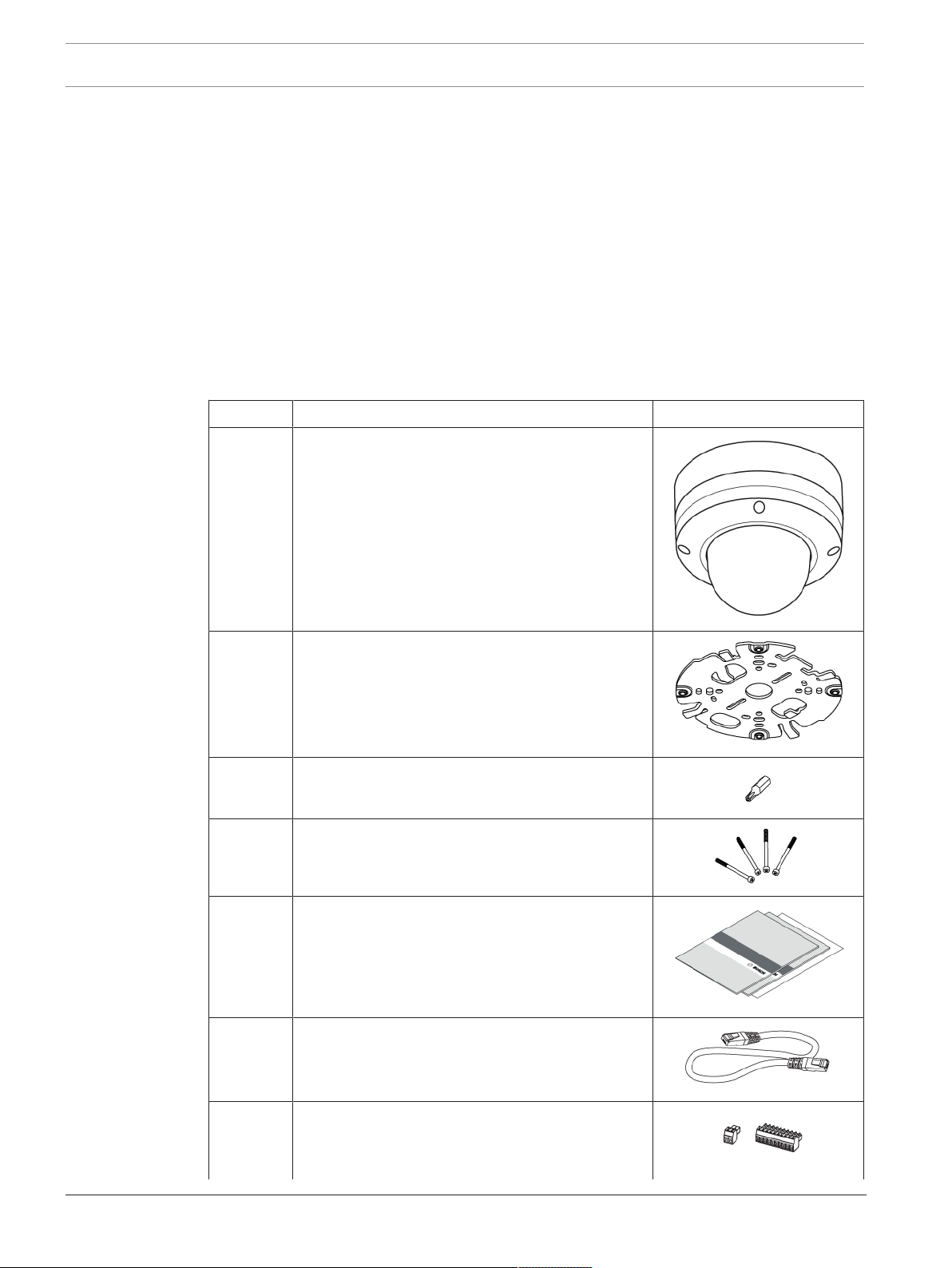
3.2 Contents
The packaging contains:
Quantity Component
1 FLEXIDOME IP camera, consists of:
– Rugged metal base: for wire connections and
mechanical fixture to the surface mounting
plate
– Camera top: bubble-protected, motorized
camera in rugged housing
1 Surface mounting plate: for easy click-on
installation of camera base
1 TR20 security torx bit: for use with the camera's
TR20 screws
4 Screws (TR20): lost-proof for easier overhead
installations. Screws are fixed to the camera top
and connect it with the base.
1 each – Quick Installation Guide
– EAC booklet
– Identification label sheet
1 RJ45 patch cable
1 each – 10-pole terminal: for connecting alarm and
audio wiring
2018.11 | 01 | Installation Manual Bosch Security Systems
Page 13
FLEXIDOME IP starlight 8000i Unpacking | en
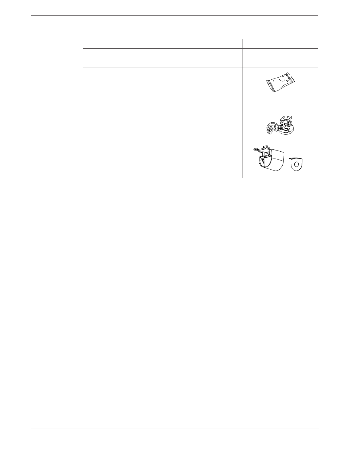
Quantity Component
– 2-pole terminal for 12VDC/24VAC
connection
1 Desiccant sachet: for additional moisture
protection in very humid environments
Note: do not open the sachet before its content
has to be used. Premature exposure to air will
render the moisture protection useless!
1 Rubber grommet: for on-site sealing of the
network connection.
1 Cable conduit: used when connecting the base to
on-surface cable routing instead of in-ceiling
cabling.
13
Bosch Security Systems Installation Manual 2018.11 | 01 |
Page 14

14
en | Hardware Installation FLEXIDOME IP starlight 8000i
4 Hardware Installation
Caution!
Do not attempt to move the camera lens manually. Do not remove the bubble.
The lens system is motorized for easy commissioning. Moving these parts manually will break
the gears and damage the camera. In order to move or focus the camera lens, always use the
commissioning apps mentioned in this manual.
Installation overview
The hardware installation of the camera summarizes in six main steps:
1. Prepare the camera
2. Install the surface mounting plate
3. Prepare the on-site wiring
4. Install the camera's base
5. Connect all wiring
6. Plug-in and fix the camera top to the base
4.1 Preparation
4.1.1 Separating base and top
On delivery, camera top and camera base are fixed together. In order to proceed with the
installation, base and top need to be separated.
Prerequisites:
– Camera unpacked
– TR20 bit mounted to screwing device
Steps:
1. Place the camera on a horizontal surface, with the flat bottom of the base facing to the
ground.
2. Use the provided TR20 security bit to unfasten the four screws, visible in their mounting
holes on the camera top. Do not use any 'similar' looking torque bit.
3. Note: do not unfasten the screws from the camera top. A second screw thread in the
camera top prevents the screws from falling down when doing an overhead installation.
4. Lift the camera top off the base.
5. Set the camera top aside for now.
4.1.2 Installing local storage
Notice!
Local storage on memory cards should only be used for alarm recording. To minimize the risk
of losing information, use multiple, redundant recording systems and a procedure to back up
all digital information.
Up to two local memory cards (SD) can be installed in the camera top.
Prerequisites
– The camera top, detached from the base
– One or two SD memory cards
Steps
1. Carefully turn around the camera top. The bubble faces down.
2. Locate the SD slot on the backside of the camera top.
2018.11 | 01 | Installation Manual Bosch Security Systems
Page 15

FLEXIDOME IP starlight 8000i Hardware Installation | en
3. Slide one card into one slot.
4. Press the card firmly until it latches into place in the slot. To remove the card, press it
into the slot until it unlatches again.
5. To install a second card, repeat from step 3 with the remaining free slot.
4.2 Installing the surface mounting plate
4.2.1 Fixing
The surface mounting plate is used to fix the camera to a wall or ceiling. The plate can be
configured for in-ceiling or on-surface cable routing:
15
In-ceiling cable routing On-surface cable routing
with cable duct.
The camera base sits flat on the surface. There are no flush-mount parts and thus no need to
cut out or drill large recess holes.
Mounting options
The surface mounting plate offers different holes and slots for a variety of fixing options. The
following graphic illustrates the different applications:
Bosch Security Systems Installation Manual 2018.11 | 01 |
Page 16

16
en | Hardware Installation FLEXIDOME IP starlight 8000i
Figure4.1: Prepared for different applications
1 4“ Square junction box 2 Ceiling/wall mount and Pendant
interface plate (NDA-8000-PIP)
3 Pole mount
4 Double gang box
(NDA-U-PMAL/NDA-U-PMAS)
5 Single Gang box and universal slot,
45mm to 85mm
Note: Only options 1,2 and 3 must be
used to maintain IK10 rating!
Fixing the surface mounting plate to a surface
Prerequisites
– Choose studs/screws and wall plugs/anchors according to the on-site situation.
– On-site cabling: available cable length must not exceed 30 cm in order to fit in the
confined space between base and camera top.
– Have the mounting plate available. You will use it as a drilling template.
– Power drill and suitable drill bit.
Proper alignment
In two application scenarios, the surface mounting plate needs proper alignment:
1. If a weather protector will be used with a wall-mounted camera, the camera base must be
leveled to facilitate the horizontal alignment of the weather protector. To achieve this,
orient the mounting plate as shown in this illustration:
2018.11 | 01 | Installation Manual Bosch Security Systems
Page 17

FLEXIDOME IP starlight 8000i Hardware Installation | en
1. For on-ceiling cable routing, the cable conduit must be oriented towards the cable duct.
17
(Preliminary picture)
Steps
1. Use the mounting plate to mark the bore holes on the surface. Note: With in-ceiling cable
routing, make sure to have the plate centered over the cable outlet. The cable will be
passed through the center hole. The cabling must not get stuck between the surface and
the plate!
2. Drill four holes. Choose the right holes combination for your application.
3. Place your wall plugs or anchors.
4. For in-ceiling cabling only: pass the cable through the center hole of the surface mounting
plate.
5. Place the plate onto the bore holes. Make sure to proper align to the correct holes on the
plate.
6. Fasten the screws or studs. Torque for fastening must exceed 4 NM and shall not exceed
7 NM.
7. Check for firm hold of the plate.
Fixing the surface mounting plate is finished.
Vandal-proof installation according to IK10 standard
To maintain the IK10+ rating of the installation, screws or anchors used must meet the
following specifications:
– Use no less than 4 screws or studs.
– Only use the appropriate holes. Do not use the long slots in the plate for mounting.
– Use 5mm screws and wall plugs or M5 anchor bolts only.
4.2.2 Preparing for in-ceiling or on-surface cable routing
The surface mounting plate in its delivery state can be used for in-ceiling cable routing without
further configuration.
To prepare for connecting to the camera base: Use the hooks on the surface mounting plate to
secure the cable and to form a service loop. Note: excessive cable lengths (> 30cm) will not
fit into the confined space between camera base and surface mounting plate.
Bosch Security Systems Installation Manual 2018.11 | 01 |
Page 18

18
en | Hardware Installation FLEXIDOME IP starlight 8000i
Preparing for on-surface cable routing
For on-surface cable routing, a cable conduit is available in the package.
This conduit consists of five parts:
– The conduit plate gets fixed to the surface mounting plate. Choose from ¾” / M25 or ½” /
M20 interfacing plate to suit different round cable ducts.
– The conduit cover gets fixed to the conduit plate.
– The rubber washer is a grommet, closing the gap between wiring and the conduit plate.
1. Conduit plate
2. M25 interfacing plate
3. Rubber washer
4. M20 interfacing plate
5. Conduit cover
Prerequisites:
The surface mounting plate has been fixed to a surface.
Steps:
1. Prepare the conduit plate to fit the cable duct by choosing the appropriate interfacing
plate (M20 or M25). Slide the interfacing plate into the conduit plate.
2. Put the conduit plate onto the surface mounting plate. Note: the conduit plate has two
tabs. The tabs fit into two slots of the mounting plate. Due to the asymmetric form, there
is only one way to slide the conduit plate into these slots.
2018.11 | 01 | Installation Manual Bosch Security Systems
Page 19

FLEXIDOME IP starlight 8000i Hardware Installation | en
1, 2 Tabs 3,4 Slide-in slots
3. Pass the external cable through the center hole of the conduit plate.
19
4. Use the hooks on the surface mounting plate to secure the cable and to form a service
loop. Note: excessive cable lengths (> 30cm) will not fit into the confined space between
camera base and camera top.
5. Slide the conduit cover onto the conduit plate.
6. Secure the conduit cover: use the TR20 bit to fasten the screw.
Bosch Security Systems Installation Manual 2018.11 | 01 |
Page 20

20
en | Hardware Installation FLEXIDOME IP starlight 8000i
The installation of the cable conduit is finished.
Preparing the camera top for on-surface cable routing
There is a lid on the camera top which has to be removed in order to have the required space
for the cable duct.
Preliminaries
A Phillips screwdriver
Steps
1. Unfasten and remove the screw
2. Remove the lid
Keep both parts in a safe space for later use.
4.3 Wiring
Caution!
The unit has connection terminals on flying leads. In wet or outdoor installations, use a field
wiring box with NEMA Type 4X or IP66 protection level or better. After connections are made,
ensure the watertight compartment is tightly closed and cables and conduits are properly
sealed to prevent water ingress.
Notice!
Use proper surge suppression on cables that are routed outdoors, or close to large inductive
loads or electrical mains supply cables.
4.3.1 Input/output connector
Use the 10-pin terminal for on-site cable commissioning. The terminal fits into its counterpart
on the camera base.
2018.11 | 01 | Installation Manual Bosch Security Systems
Page 21

FLEXIDOME IP starlight 8000i Hardware Installation | en
Pin assignment
Pin Connection
1 12V out
2 GND
3 ALARM OUT
4 ALARM OUT
5 GND
6 ALARM IN 1
7 ALARM IN 2
8 GND
9 AUDIO OUT
10 AUDIO IN
Tab.4.1: Pin assignment for 10-pin terminal
21
After fitting the terminal to an on-site wiring, the connection can easily be made. Plug the
terminal into the 10-pin I/O on the camera base.
Figure4.2: Connectors on the base
1 10-pin connector 2 RJ45 Ethernet/PoE connector
3 12VDC/24VAC connector
4.3.2 Grounding
The camera is double-insulated and does not need grounding. However, grounding provides
improved surge protection (up to 1kV).
The grounding connector suits cable diameters from 1mm up to 4mm. The following graphic
illustrates the position of the grounding connector:
Steps:
Warning!
Trained electricians only!
Work at electric appliances must only be carried out by qualified technicians.
1. Remove any power source from the device.
Bosch Security Systems Installation Manual 2018.11 | 01 |
Page 22

22
en | Hardware Installation FLEXIDOME IP starlight 8000i
2. Unfasten the connector screw to lift it from the metal bracket underneath. Do not remove
the connector screw completely. The gap between the washer and the bracket shall suit
the diameter of the grounding wire.
3. Prepare your grounding wire.
4. Lift the washer and place the wire into the gap between washer and bracket.
5. Fasten the connector screw. Take care that the wire does not slip off the gap. Check the
installation before re-connecting a power device.
4.3.3 Network (and PoE power)
Connect the camera to a 10/100 Base-T network:
– Use STP Category 5e cable with RJ45 connectors (the camera network socket is
AutoMDIX compliant).
– Power is supplied to the camera via the Ethernet cable compliant with the Power-over-
Ethernet standard.
Notice!
Use only PoE approved devices.
Power-over-Ethernet (PoE) can be connected at the same time as a 12VDC or 24VAC power
supply. If auxiliary power (12VDC/24VAC) and PoE is applied simultaneously, the camera
selects PoE and shuts off the auxiliary input.
4.3.4 Auxiliary power
Connect a SELV-LPS or a SELV Class2 power supply with a rated supply voltage of 12VDC or
24 VAC.
For maximum reliability, the camera can be connected simultaneously to a High PoE Midspan
and a separate 24 VAC power source. If High PoE and 24 VAC are applied simultaneously, the
camera usually selects the High PoE Midspan and will draw minimal power from the auxiliary
input (24 VAC). If the High PoE Midspan power source fails, the camera switches power input
seamlessly to 24 VAC. After the High PoE Midspan power source is restored, the camera
switches power input again to the High PoE Midspan.
Caution!
Compliance with EN50130-4 Alarm Standard – CCTV for Security Applications
To meet the requirements of the EN50130-4 Alarm Standard, an ancillary uninterruptable
power (UPS) supply is necessary. The UPS must have a Transfer Time between 2–6 ms and a
Backup Runtime of greater than 5 seconds for the power level as specified on the product
datasheet.
4.3.5 Alarm
Alarm out:
Use the alarm output for switching external devices such as lamps or sirens.
The alarm output switching capability has a max. voltage of 30VAC or +40VDC; max. 0.5A
continuous, 10VA.
Alarm in:
Use the alarm input to connect external alarm devices such as door contacts or sensors:
– TTL logic, +5V nominal, +40VDC max, DC coupled with 50kOhm pull-up to +3.3V.
– Configurable as active low or active high.
2018.11 | 01 | Installation Manual Bosch Security Systems
Page 23

FLEXIDOME IP starlight 8000i Hardware Installation | en
Use a zero potential make-contact or switch as the actuator (with a bounce-free contact
system).
4.3.6 12V output
The 12V output can be controlled by the Alarm Task editor and it can be enabled via the web
interface.
4.3.7 Audio
Connect audio devices to the audio input and audio output connectors.
The unit has full-duplex mono audio for two-way communication between a speaker or door
intercom system. The audio input signal is transmitted in sync. with the video signal.
Audio input:
Line input level (not suitable for direct microphone signal); impedance 18kOhm typical;
1Vrms maximum input voltage.
Audio output:
Line output level (not suitable for direct speaker connection); impedance 1.5kOhm minimum;
0.85Vrms maximum output voltage.
Use shielded audio connection cable with advised maximum cable lengths for audio line input
and output levels.
23
4.4 Mounting the camera
After installing the surface mounting plate, the camera base needs to get connected and
installed.
Preliminaries
– Surface mounting plate installed (and prepared for on-ceiling cable routing, if necessary)
– Camera base and top separated
– On-site wiring (network, power, alarm, 12V, audio) prepared, terminal installed
– Network cabling wound in a service loop
– PoE power supplies or 12V/24V power supplies switched off and disconnected from
power sources.
4.4.1 Mounting the base
Installing the base is a simple, tool-free, click-on process.
Steps
1. Locate the network cable inlet (1) and pass the network cable into the base.
Bosch Security Systems Installation Manual 2018.11 | 01 |
Page 24

24
en | Hardware Installation FLEXIDOME IP starlight 8000i
1 Network cable inlet 2 Sealed cable inlet with adjustable
rubber grommet
3
Ventilation holes. Note: Never remove
or break the sealing from these holes.
Check safety chapter for further
information.
2. Insert the RJ45 plug into the RJ45 network connector.
3. Attach the grommet to the network cable, with the larger diameter facing the RJ45 plug.
Note: The grommet will seal round-shaped network cables with a diameter of 5mm to
8mm. The grommet will not seal the housing if flat, oval or wrinkled network cables are
used. In this case you need to take further measures (e.g. silicone sealant) to seal the
cabling.
4. Insert the grommet into the network cable inlet. Note: the grommet does not slide in
easy. Grab the base with both hands and use both thumbs to push the grommet into the
inlet. Do not use any lubricant as this would harm the sealing.
2018.11 | 01 | Installation Manual Bosch Security Systems
Page 25

FLEXIDOME IP starlight 8000i Hardware Installation | en
5. Make sure that the grommet is pushed in to its full length:
6. Place the camera base onto the surface mounting plate.
7. Turn the camera base clockwise until you hear a ‘click’ sound.
25
8. Check the correct, seamless seating of the base.
The base is mounted.
4.4.2 Handling additional cabling
4.4.3 Mounting the camera top
Notice!
Optional moisture protection
If fogging occurs during installation, you have to install the optional moisture protection. In
this case, you must finish the whole installation of the camera top within 10 minutes,
otherwise the moisture protection will be useless!
Installing the optional moisture protection
The desiccant sachet contains a pill. This self-adhesive pill will be affixed to the camera base
and provides moisture protection if fogging occurs during installation.
Bosch Security Systems Installation Manual 2018.11 | 01 |
Page 26

26
en | Hardware Installation FLEXIDOME IP starlight 8000i
Steps
1. Open the sachet and take out the pill. From now you have 10 minutes to complete the
whole installation.
2. Remove the protective cover from the adhesive side of the pill.
3. Affix the pill to the base, on the left side of the cable inlets. Be sure not to cover the
ventilation hole.
4. Proceed with the installation of the camera top immediately.
Installing the camera top
The camera top connects to the base through a built-in plug/socket connector. To achieve this
connection, camera top and base have to be aligned properly.
To facilitate proper alignment, top and base are marked with a triangle on their inside. Align
these triangles before mounting the top.
Preliminaries
Screwing tool with TR20 bit installed.
Steps
1. Align camera top to camera base.
2. Put the camera top onto the base, with no gap between top and base. This has to fit
easily. Do not use physical force if it doesn’t fit! Check for proper alignment instead!
3. While holding the camera top with one hand, use the other hand to hand-tighten two
opposing bolts.
2018.11 | 01 | Installation Manual Bosch Security Systems
Page 27

FLEXIDOME IP starlight 8000i Hardware Installation | en
4. Use the screwing tool to fasten all four bolts. Apply at least 2.5Nm of torque, but no
more than 4Nm.
5. Remove the protective cover from the bubble.
27
The hardware installation is complete.
Note: Recall that this device has motorized PTZ setup. Do not remove the bubble. Do not
move the camera manually.
Bosch Security Systems Installation Manual 2018.11 | 01 |
Page 28

28
en | Online Camera Commissioning FLEXIDOME IP starlight 8000i
5 Online Camera Commissioning
Once the hardware installation is completed,
– the camera has to be integrated into your network and
– the field of view needs to be set.
The camera’s initial setup is done via the camera’s browser interface or, preferably, via the
free-of-charge Bosch Project Assistant app.
5.1 Downloading the Project Assistant app
The Project Assistant app is available for Android, iPhone and Windows. The app is free of
charge. You can find the app in the respective app stores.
Scan this QR code with your mobile phone to navigate directly to the appropriate store page.
5.2 Introducing the Project Assistant app
On the following pages we describe the use of the Project Assistant app for a single camera
setup. But the app has much more to offer:
Installation
The Project Assistant app covers all basic camera settings like name, password, network
settings, date and time, and the camera's field of view alignment.
Identification of camera
Local area network scans, direct connection via IP address, and QR-code scan for MACaddress import and automatic connection are available to identify cameras.
Single Camera Assistant
The quick mode allows you to connect to a camera and set basic camera setting online
without having to go through the project setup phase beforehand.
2018.11 | 01 | Installation Manual Bosch Security Systems
Page 29

FLEXIDOME IP starlight 8000i Online Camera Commissioning | en
29
Project Assistant
The Project Assistant app allows you to cluster and preconfigure cameras in projects. Project
defaults can be defined for network settings and passwords and are automatically used for
added cameras. Both project defaults and dedicated camera configurations can be defined
offline and pushed onto the cameras when connecting. Project and camera settings can also
be exported to as well as imported from project and .csv files (for example Excel).
Sharing of projects
Project files can be exported and transferred to associates via email or cloud service, for
example in case another project team member is taking over from someone else. The most
convenient way, however, is our Dropbox synchronization and sharing feature which allows
multiple people to work on the same project simultaneously or to monitor real-time progress.
Thus, easy collaboration and installation process monitoring is supported even for large sites.
Reporting
The app allows you to easily generate reports and documentation of the status of projects.
The reports contain relevant project and camera settings as well as snapshots of the camera’s
field of view.
Please refer to the Project Assistant online help for in-depth information on the features.
5.3 Using the Project Assistant app
Bosch Security Systems Installation Manual 2018.11 | 01 |
Page 30

30
en | Online Camera Commissioning FLEXIDOME IP starlight 8000i
Notice!
Do not expose the image sensors to direct sunlight.
2018.11 | 01 | Installation Manual Bosch Security Systems
Page 31

FLEXIDOME IP starlight 8000i Connection via the web browser | en
6 Connection via the web browser
The unit must have a valid IP address and a compatible subnet mask to operate on your
network. By default, DHCP is pre-set at the factory to On and so your DHCP server assigns an
IP address. With no DHCP server the default address is 192.168.0.1
To view the camera in your web browser:
1. Start the Web browser.
2. Enter the IP address of the unit as the URL.
3. During initial installation, confirm any security questions that appear.
Note:
To see live images in your browser it might be necessary to download and install the MPEGActiveX from the Bosch download store.
Protected Network
If a RADIUS server is used for network access control (802.1x authentication), the unit must
be configured first. To configure the unit, connect it directly to a computer using a network
cable and configure the two parameters, Identity and Password. Only after these have been
configured can communication with the unit via the network occur.
IP Helper tool
Alternatively, use the IP Helper tool to detect Bosch devices on the network:
1. Access the Bosch download store (http://downloadstore.boschsecurity.com/).
2. Download and install IP Helper.
3. Choose your specific camera from the list of cameras shown in the table on the left of the
screen
4. Click Open in browser to view the camera interface.
31
Bosch Security Systems Installation Manual 2018.11 | 01 |
Page 32

32
en | Troubleshooting FLEXIDOME IP starlight 8000i
7 Troubleshooting
7.1 Resolving problems
The following table is intended to help identify the causes of malfunctions and correct them
where possible.
Malfunction Possible causes Solution
Unit does not operate. Power failure. Check power supply.
Faulty cable connections. Check all cables, plugs,
contacts and connections.
No connection
established, no image
transmission.
No audio transmission to
remote station.
Incorrect unit configuration. Check all configuration
parameters (reset to factory
default if necessary).
Faulty installation. Check all cables, plugs,
contacts and connections.
Wrong IP address. Check the IP addresses (ping).
Faulty data transmission within
the LAN.
The maximum number of
connections has been reached.
Hardware fault. Check that all connected audio
Faulty cable connections. Check all cables, plugs,
Incorrect configuration. Check audio parameters on the
Check the data transmission
with ping.
Wait until there is a free
connection and call the
transmitter again.
units are operating correctly.
contacts and connections.
Audio configuration and LIVE
page functions pages.
The audio voice connection is
already in use by another
receiver.
The unit does not report
an alarm.
The unit is not
operational after a
firmware upload.
2018.11 | 01 | Installation Manual Bosch Security Systems
Alarm source is not selected. Select possible alarm sources
No alarm response specified. Specify the desired alarm
Power failure during
programming by firmware file.
Wait until the connection is free
and then call the sender again.
on the Alarm sources
configuration page.
response on the Alarm
connections configuration page;
if necessary change the IP
address.
Have the unit checked by
Customer Service and replace if
necessary.
Page 33

FLEXIDOME IP starlight 8000i Troubleshooting | en
Incorrect firmware file. Enter the IP address of the unit
followed by /main.htmin your
Web browser and repeat the
upload.
33
Web browser contains
empty fields.
Active proxy server in network. Create a rule in the local
7.2 Testing the network connection
The ping command can be used to check the connection between two IP addresses. This
allows testing whether a device is active in the network.
1. Open the DOS command prompt.
2. Type ping followed by the IP address of the device.
If the device is found, the response appears as "Reply from ... ", followed by the number of
bytes sent and the transmission time in milliseconds. Otherwise, the device cannot be
accessed via the network. This might be because:
– The device is not properly connected to the network. Check the cable connections in this
case.
– The device is not correctly integrated into the network. Check the IP address, subnet
mask, and gateway address.
7.3 Customer service
If a fault cannot be resolved, please contact your supplier or system integrator, or go directly
to BoschSecuritySystems Customer Service.
The version numbers of the internal firmware can be viewed on a service page. Please note
this information before contacting Customer Service.
1. In the address bar of your browser, after the unit IP address, enter: /version
for example: 192.168.0.80/version
2. Write down the information or print out the page.
computer's proxy settings to
exclude local IP addresses.
Bosch Security Systems Installation Manual 2018.11 | 01 |
Page 34

34
en | Maintenance FLEXIDOME IP starlight 8000i
8 Maintenance
8.1 Cleaning
It is generally sufficient to use a dry cloth for cleaning, but a moist lint-free cloth or leather
shammy may also be used.
Do not use liquid cleaners or aerosol cleaners.
8.1.1 Lens cleaning
It is important to keep the lens clean to ensure optimum performance. Dust, grease, or
fingerprints should be removed from the lens surface. When cleaning the lens, take extra care
not to damage the special coating used to reduce light reflections.
– Remove dust with a blower-brush or grease-free soft brush.
– Wipe water drops off the lens with a clean soft lint-free cloth and dry the lens surface.
– Use special lens cleaning paper or cloth treated with lens cleaning fluid to gently wipe off
any remaining dirt (wipe spirally from the lens center towards the edge).
8.2 Repair
Notice!
Never open the casing of the unit
The unit does not contain any user-serviceable parts. Refer all repairs to suitable qualified
specialists.
2018.11 | 01 | Installation Manual Bosch Security Systems
Page 35

FLEXIDOME IP starlight 8000i Decommissioning | en
9 Decommissioning
9.1 Transfer
The unit should only be passed on together with this installation guide.
9.2 Disposal
Disposal - Your Bosch product was developed and manufactured with high-quality
material and components that can be recycled and reused. This symbol means that
electronic and electrical appliances, which have reached the end of their working life,
must be collected and disposed of separately from household waste material.
Separate collecting systems are usually in place for disused electronic and electrical
products. Please dispose of these units at an environmentally compatible recycling
facility, per European Directive 2012/19/EU.
35
Bosch Security Systems Installation Manual 2018.11 | 01 |
Page 36

36
en | Technical data FLEXIDOME IP starlight 8000i
10 Technical data
10.1 Dimensions
Figure10.1: FLEXIDOME IP 8000i dimensions
10.2 Specifications
Mechanical
Dimensions (DxH) 175x145mm (6.9x5.7in)
Weight 2.2kg (4.85lbs)
Mounting Surface mount
Color White (RAL9010)
Motorized PTR range Pan: -181.5º to +181.5º
Dome bubble Polycarbonate, clear with UV blocking anti-scratch coating
Housing Aluminum with dehumidifying membranes and waterproof
Environmental
Operating temperature -50ºC to +60ºC (-58ºF to +140ºF) for continuous
Tilt: -5.5º to +87º (NDE-8502-R), -5.5º to +90º (NDE-8502RT)
Roll: -92º to +92º
connection area
operation;
2018.11 | 01 | Installation Manual Bosch Security Systems
Page 37

FLEXIDOME IP starlight 8000i Technical data | en
Environmental
-34ºC to +74ºC (-30ºF to +165ºF) according to NEMA TS
2-2003 (R2008), para2.1.5.1 using fig.2.1 test profile
Storage temperature -30ºC to +70ºC (-22ºF to +158ºF)
Operating humidity 5% to 93% RH non condensing
5% to 100% RH condensing
Storage humidity Up to 98% RH
37
Impact resistance casing and
IK10+ (50 joules)
dome
Water/dust protection IP66 and NEMA Type 4X
Power
Input voltage PoE IEEE 802.3af / 802.3at Type1, Class3
24VAC ±10%
12-26VDC ±10%
PoE and auxiliary power can be connected simultaneously for
redundant operation
Power Consumption
(typical / maximum)
PoE: 7W / 13W
24VAC: 7.1W - 12VA / 13W - 25VA
12-26VDC: 7.5W / 16W
Input/output
Power output +12VDC, max 50mA
Audio signal line in 10kOhm typical; 1Vrms max
Audio signal line out 1Vrms; 1.5kOhm typical
Alarm input 2 inputs, activation voltage: +3.3VDC to +40VDC
Alarm output 1 output, maximum: 30VAC or +40VDC, 0.5A continuous,
10VA
Ethernet RJ45
Surge protection Ethernet: 1kV, 2kA to ground (8/20µs pulse)
Fiber optics (sold separately) The Fiber Optic Ethernet Media Converter kit (VG4-
SFPSCKT) installed inside a Surveillance Cabinet (NDA-UPA0, NDA-U-PA1 or NDA-U-PA2) provides the fiber optic
interface to the mounted camera.
Network
Protocols IPv4, IPv6, UDP, TCP, HTTP, HTTPS, RTP/RTCP, IGMP V2/V3,
ICMP, ICMPv6, RTSP, FTP, ARP, DHCP, APIPA (Auto-IP, link
local address), NTP (SNTP), SNMP(V1,V3, MIB-II), 802.1x,
DNS, DNSv6, DDNS (DynDNS.org, selfHOST.de, no-ip.com),
SMTP, iSCSI, UPnP(SSDP), DiffServ(QoS), LLDP, SOAP,
Dropbox™, CHAP, digest authentication
Bosch Security Systems Installation Manual 2018.11 | 01 |
Page 38

38
en | Technical data FLEXIDOME IP starlight 8000i
Network
Ethernet 10/100 Base-T, auto-sensing, half/full duplex
Connectivity Auto-MDIX
Interoperability ONVIF ProfileS; ONVIF Profile G; ONVIF Profile T
GB/T 28181
Camera installation
Mirror image On / Off
Rotate 0° / 90° upright / 180° / 270° upright
Camera LED Enable/disable
Positioning Coordinates / Mounting height
Camera View Wizard Motorized pan, tilt, roll, zoom, autofocus
Video streaming
Video compression H.265; H.264; M- JPEG
Sensor modes 25fps, HDR, 1920 x 1080 (2MP)
30fps, HDR, 1920 x 1080 (2MP)
50fps, 1920 x 1080 (2MP)
60fps, 1920 x 1080 (2MP)
Streaming Multiple configurable streams in H.264, H.265 and M-JPEG,
configurable frame rate and bandwidth.
Regions of Interest (ROI)
Bosch Intelligent Streaming
Camera latency 67ms (2MP, 60fps)
GOP structure IP, IBP, IBBP
Frame rate 1-60fps
Signal-to-Noise Ratio (SNR) >55dB
Audio streaming
Standard G.711, 8kHz sampling rate
L16, 16kHz sampling rate
AAC-LC, 48kbps at 16kHz sampling rate
AAC-LC, 80kbps at 16kHz sampling rate
Signal-to-Noise Ratio >50dB
Audio Streaming Full-duplex / half duplex
Local storage
Internal RAM 5s pre-alarm recording
Memory card slots Dual SDXC / SDHC / SD card slots.
Dual SD-card slot
configurations
2018.11 | 01 | Installation Manual Bosch Security Systems
– Mirror (redundant storage)
– Failover (extended service interval)
Page 39

FLEXIDOME IP starlight 8000i Technical data | en
Local storage
– Extend (maximum retention time)
– Automatic Network Replenishment
Industrial SD cards Extreme lifetime and health monitoring support that provides
early service indication.
SR-32VMA (32GB),
SR-64VMA (64GB),
SR-G1VMA (128GB)
Data security
Crypto Coprocessor (TPM) RSA 2048 bit, AES/CBC 256 bit
FIPS FIPS 140-2 Level 3 compliant
PKI X.509 certificates
Encryption Full end-to-end encryption with supported VMS
Network: TLS1.0/1.2, AES128, AES256
Local storage: XTS-AES
39
Video authentication checksum, MD5, SHA-1, SHA-256
Optical (10 to 23mm lens)
Lens 10 to 23mm P-iris lens (IR corrected)
F-stop 1.6 - 2.6
Adjustment Motorized zoom/focus
Iris control P-iris control
Viewing angle Wide: 32º x 18º (H x V)
Tele: 14.4º x 8.1º (H x V)
Optical (3 to 9mm lens)
Lens 3 to 9mm P-iris lens (IR corrected)
F-stop 1.2 - 2.3
Adjustment Motorized zoom/focus
Iris control P-iris control
Viewing angle Wide: 117º x 59º (H x V)
Tele: 37º x 21º (H x V)
2 MP version
Video resolution (H x V)
1080p HD 1920x1080
Upright mode 1080p HD 1080x1920
1.3MP (5:4) 1280x1024
720p HD 1280x720
Upright mode 720p 720x1280
Bosch Security Systems Installation Manual 2018.11 | 01 |
Page 40

40
en | Technical data FLEXIDOME IP starlight 8000i
Video resolution (H x V)
480p SD 854x480
SD 4:3 (cropped) 704 x 480
6 MP version
Video resolution (H x V)
6.0MP 3264 x 1840
5.3MP 3072 x 1728
2.8MP (4:3) 1920x1440
1080p HD 1920x1080
1.3MP (5:4) 1280x1024
720p HD 1280x720
480p SD 854x480
SD 4:3 (cropped) 704 x 480
8 MP version
Video resolution (H x V)
4K UHD 3840x2160
7.3MP 3584x2016
2.8MP (4:3) 1920x1440
1080p HD 1920x1080
Upright mode 1080p 1080x1920
1.3MP (5:4) 1280x1024
720p HD 1280x720
Upright mode 720p 720x1280
480p SD 854x480
SD 4:3 (cropped) 704x480
2018.11 | 01 | Installation Manual Bosch Security Systems
Page 41

Page 42

Bosch Security Systems B.V.
Torenallee 49
5617 BA Eindhoven
Netherlands
www.boschsecurity.com
© Bosch Security Systems B.V., 2018
 Loading...