

Page 1
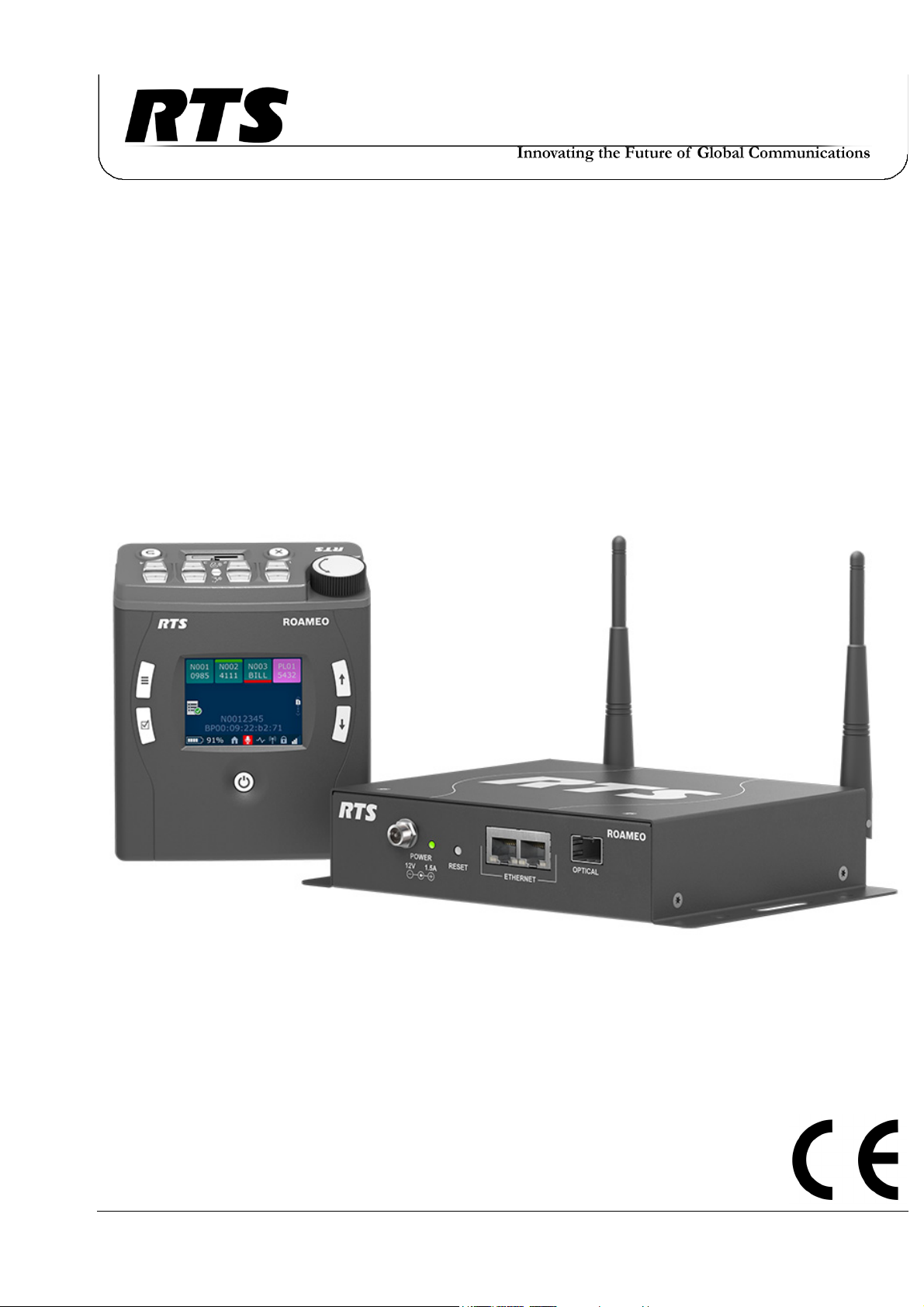
ROAMEO Family
Wireless Intercom System
•TR-1800
•AP-1800
F.01U.306.750
Rev. 01
APRIL/2017
Page 2
2 ROAMEO System
PROPRIETARY NOTICE
The product information and design disclosed herein were originated by and are the property of Bosch Security Systems, Inc.
Bosch reserves all patent, proprietary design, manufacturing, reproduction, use and sales rights thereto, and to any article disclosed
therein, except to the extent rights are expressly granted to others.
COPYRIGHT NOTICE
Copyright 2017 by Bosch Security Systems, Inc. All rights
reserved. Reproduction, in whole or in part, without prior written
permission from Bosch is prohibited.
*All other trademarks are property of their respective owners.
WARRANTY AND SERVICE INFORMATION
For warranty and service information, refer to the appropriate web
site below:
RTS Intercoms .............................. www.rtsintercoms.com/warranty
RTS Digital
RTSTW
AudioCom
Wireless Intercom
Intercom Headsets
CUSTOMER SUPPORT
Technical questions should be directed to:
Customer Service Department
Bosch Security Systems, Inc.
www.telex.com
THE LIGHTNING
FLASH AND
ARROWHEAD
WITHIN THE
TRIANGLE IS A
WARNING SIGN
ALERTING YOU
OF “DANGEROUS
VOLTAGE”
INSIDE THE
PRODUCT.
SEE MARKING ON BOTTOM/BACK OF PRODUCT.
WARNING: APPARATUS SHALL NOT BE EXPOSED TO DRIPPING OR
SPLASHING AND NO OBJECTS FILLED WITH LIQUIDS, SUCH AS
VASES, SHALL BE PLACED ON THE APPARATUS.
WARNING: THE MAIN POWER PLUG MUST REMAIN READILY OPERABLE.
CAUTION: TO REDUCE THE RISK OF ELECTRIC SHOCK, GROUNDING
OF THE CENTER PIN OF THIS PLUG MUST BE MAINTAINED.
WARNING: TO REDUCE THE RISK OF FIRE OR ELECTRIC SHOCK, DO
NOT EXPOSE THIS APPARATUS TO RAIN OR MOISTURE.
WARNING: TO PREVENT INJURY, THIS APPARATUS MUST BE
SECURELY ATTACHED TO THE FLOOR/WALL/RACK IN ACCORDANCE WITH THE INSTALLATION INSTRUCTIONS.
CAUTION: TO REDUCE
THE RISK OF ELECTRIC
SHOCK, DO NOT
REMOVE COVER. NO
USER-SERVICEABLE
PARTS INSIDE. REFER
SERVICING TO
QUALIFIED SERVICE
PERSONNEL.
THE
EXCLAMATION
POINT WITHIN THE
TRIANGLE IS A
WARNING SIGN
ALERTING YOU OF
IMPORTANT
INSTRUCTIONS
ACCOMPANYING
THE PRODUCT.
DECLARATION OF CONFORMITY
The full Declaration of Conformity may be found on the product
page at www.rtsintercoms.com.
TECHNICAL QUESTIONS EMEA
Bosch Security Systems Technical Support EMEA
http://www.rtsintercoms.com/contact_main.php
DISCLAIMER
The manufacturer of the equipment described herein makes
no expressed or implied warranty with respect to anything
contained in this manual and shall not be held liable for any
implied warranties of fitness for a particular application or
for any indirect, special, or consequential damages. The
information contained herein is subject to change without
prior notice and shall not be construed as an expressed or
implied commitment on the part of the manufacturer.
This product is AC and DC.
Bosch Security Systems, Inc.
Technical Manual
F.01U.306.750
Rev. 01
Page 3

ROAMEO System 3
Important Safety Instructions
1. Read these instructions.
2. Keep these instructions.
3. Heed all warnings.
4. Follow all instructions.
5. Do not use this apparatus near water.
6. Clean only with dry cloth.
7. Do not block any ventilation openings. Install in accordance with the manufacturer’s
instructions.
8. Do not install near any heat sources such as radiators, heat registers, stoves, or other
apparatus (including amplifiers) that produce heat.
9. Do not defeat the safety purpose of the polarized or grounding-type plug. A polarized
plug has two blades with one wider than the other. A grounding type plug has two blades
and a third grounding prong. The wide blade or the third prong are provided for safety. If
the provided plug does not fit into the outlet, consult an electrician for replacement of the
obsolete outlet.
10. Protect the power cord from being walked on or pinched particularly at plugs,
convenience receptacles, and the point where they exit from the apparatus.
11. Only use attachments/accessories specified by the manufacturer.
12. Use only with the cart, stand, tripod, bracket, or table specified by the manufacturer, or
sold with the apparatus. When a cart is used, use caution when moving the cart/apparatus
combination to avoid injury from tip-over.
13. Unplug this apparatus during lightning storms or when unused for long periods of time.
14. Refer all servicing to qualified service personnel. Servicing is required when the
apparatus has been damaged in any way, such as power-supply cord or plug is damaged,
liquid has been spilled or objects have fallen into the apparatus, the apparatus has been
exposed to rain or moisture, does not operate normally, or has been dropped.
15. Do not disassemble or subject batteries to impact.
16. Do not operate or charge a battery that has been damaged.
17. Never heat the Li-Ion batteries or throw them into a fire.
18. Charging the Li-Ion batteries in temperatures below freezing can cause permanent
damage.
19. Store the batteries in a cool, dry ventilated area.
20. Dispose of Li-Ion batteries properly.
21. Before flying with the ROAMEO system, consult the airline regulations concerning the
Lithium batteries.
22. Use only the manufacturer’s supplied charger to charge the batteries.
Bosch Security Systems, Inc.
Technical Manual
F.01U.306.750
Rev. 01
Page 4

4 ROAMEO System
Bosch Security Systems, Inc.
Technical Manual
F.01U.306.750
Rev. 01
Page 5

Table
of
Contents
Important Safety Instructions ..............................................................................................................................3
Chapter 1 : Certification Information ........................................................................................11
FCC ....................................................................................................................................................... 11
Industry Canada .................................................................................................................................... 12
Europe ................................................................................................................................................... 13
Chapter 2 : Introduction .............................................................................................................15
General Description .............................................................................................................................. 15
Features ................................................................................................................................................ 15
Controls, Connections, and Specifications ........................................................................................... 16
TR-1800 Reference View ..................................................................................................................................16
TR-1800 Connections ........................................................................................................................................17
XLR - 5-Pin Female .......................................................................................................................................17
3.5mm Auxiliary Jack ...................................................................................................................................17
Headset Mode ..............................................................................................................................................17
USB Jack - Type A .........................................................................................................................................18
Charging Jack .................................................................................................................................................18
TR-1800 Specifications .....................................................................................................................................19
AP-1800 Reference View ..................................................................................................................................20
AP-1800 Connections ........................................................................................................................................21
Dual Ethernet Connectors ..............................................................................................................................21
Fiber Optic Connector ....................................................................................................................................21
Power Connector ............................................................................................................................................21
Antenna Connector .........................................................................................................................................21
AP-1800 Specifications .....................................................................................................................................22
Frequencies Of Operation .................................................................................................................... 23
ETSI Defined RF Channels for DECT ..............................................................................................................23
Bosch Security Systems, Inc.
Technical Manual
F.01U.306.750
Rev. 01
Page 6

6 ROAMEO System
Chapter 3 : System Overview ......................................................................................................25
System Description ................................................................................................................................25
System Considerations ...................................................................................................................................25
Access Points .........................................................................................................................................26
Home AP ...........................................................................................................................................................26
Visitor AP .......................................................................................................................................................... 26
Roaming .................................................................................................................................................27
Home Connections ............................................................................................................................................ 29
Home to Visitor Roaming .................................................................................................................................30
System Drawings ....................................................................................................................................31
Small System .....................................................................................................................................................31
Medium System ................................................................................................................................................. 34
Large System ..................................................................................................................................................... 36
ROAMEO System Setup Checklist .........................................................................................................38
Chapter 4 : Site Survey ...............................................................................................................39
Description .............................................................................................................................................39
Set Up Site Survey ..................................................................................................................................39
Requirements ..................................................................................................................................................... 39
Prepare the Hardware ........................................................................................................................................39
Set Up an Existing System with a Static IP Address ..................................................................................... 40
Add the Access Point to IPedit ....................................................................................................................... 43
Assign the TR-1800 to an AP-1800 Channel ................................................................................................. 44
Subscribe the TR-1800 to the AP-1800 .........................................................................................................44
Set Up an Existing System with a Dynamic IP Address ................................................................................... 46
Perform a Site Survey ............................................................................................................................46
Pre-conditions ................................................................................................................................................... 46
Description of Site Survey Screen .................................................................................................................47
Description of RSSI ....................................................................................................................................... 47
Description of QF ...........................................................................................................................................48
Notes ......................................................................................................................................................48
Chapter 5 : Installation ............................................................................................................... 49
Access Point Placement .........................................................................................................................49
Access Point Placement .....................................................................................................................................49
Site Survey ........................................................................................................................................................ 49
RF (Radio Frequency) Considerations .............................................................................................................. 49
Mounting Options ..............................................................................................................................................50
Antenna connection and placement .................................................................................................................. 51
Wall or Ceiling Mounting .............................................................................................................................. 53
Pole Mounting ................................................................................................................................................ 54
Rail Mounting ...............................................................................................................................................54
Free-Standing Installation .............................................................................................................................. 55
AP-1800 Mounting Surfaces ............................................................................................................................. 56
Power Over Ethernet .............................................................................................................................57
PoE Splitter Recommendation .......................................................................................................................... 57
Power Up the AP-1800 Access Point ....................................................................................................58
Connecting the Access Point to the Intercom ........................................................................................59
Configure the OMI using AZedit ...................................................................................................................... 59
Add the OMI to the Device Catalog in IPedit ................................................................................................... 60
Configure the OMI using IPedit ........................................................................................................................ 60
Add the AP-1800 to IPedit ................................................................................................................................ 61
Configure the AP-1800 in IPedit ....................................................................................................................... 62
Bosch Security Systems, Inc.
Technical Manual
F.01U.306.750
Rev. 01
Page 7

ROAMEO System 7
Configure the Beltpack to its Home AP-1800 .................................................................................................. 65
First Time Operation – Beltpack ...........................................................................................................66
Battery Charge ................................................................................................................................................... 66
Quick Charge ................................................................................................................................................. 66
4-Bay LED Charge Status Description ....................................................................................................... 66
In-Device Charging ........................................................................................................................................ 67
Battery Installation and Removal ...................................................................................................................... 68
Beltclip Installation and Removal ..................................................................................................................... 69
Subscribe the Beltpack and Connect to the Access Point ................................................................................. 70
Chapter 6 : Basic Operation ....................................................................................................... 73
Intercom Keys and Displays ..................................................................................................................73
Key Assignment Types and Descriptions ......................................................................................................... 73
Color Display Descriptions for Intercom Keys ................................................................................................. 74
Display Icons .........................................................................................................................................75
Operation of Buttons with Auto-Functions ............................................................................................81
Adjusting the Volume .............................................................................................................................82
Basic Intercom Key Operation ..............................................................................................................83
Receiving a Call from an Assigned Alpha ........................................................................................................ 83
Making a Call to an Assigned Alpha ................................................................................................................ 83
Receiving a Call from an Unassigned Alpha .................................................................................................... 83
Making an Unassigned Call from the Belt Pack ............................................................................................... 84
Call Waiting Window .............................................................................................................................85
Unassigned caller calls, another unassigned caller calls ................................................................................... 85
Unassigned caller calls, an assigned caller calls ............................................................................................... 85
RSTP ......................................................................................................................................................85
Scroll Lists .............................................................................................................................................87
Tally Flash .............................................................................................................................................87
Latching vs Momentary Key Operation .................................................................................................88
Pages ......................................................................................................................................................88
How to assign a call assignment to a button on the beltpack ............................................................................ 89
Dark Mode .............................................................................................................................................90
How to activate Dark Mode .............................................................................................................................. 90
Lockout ...................................................................................................................................................90
Scroll List Shortcut ................................................................................................................................91
Chapter 7 :
Beltpack Overview ....................................................................................................................... 93
System Quick Start .................................................................................................................................93
Initial Beltpack Setup ........................................................................................................................................ 93
Button Operation – Common .................................................................................................................94
Power On the Beltpack ...................................................................................................................................... 94
Menu Structure – Main Menu Access ....................................................................................................98
Aux Input Menu ................................................................................................................................................ 99
AUX DIM Menu ............................................................................................................................................... 99
Volume Limit Menu ........................................................................................................................................ 100
Headset Select Menu ....................................................................................................................................... 100
Mic Gain .......................................................................................................................................................... 101
Sidetone ........................................................................................................................................................... 102
Mic Noise Gate ................................................................................................................................................ 102
Hot Mic ........................................................................................................................................................... 103
Talk/Listen LED Buttons ................................................................................................................................ 104
Bosch Security Systems, Inc.
Technical Manual
F.01U.306.750
Rev. 01
Page 8

8 ROAMEO System
Front Display Brightness .................................................................................................................................104
Top Display Brightness ................................................................................................................................... 105
LCD Timeout .................................................................................................................................................. 105
Call Tally Talk .................................................................................................................................................106
Screen Flip ....................................................................................................................................................... 106
Master Talk Switch ......................................................................................................................................... 107
Low Battery Alert ............................................................................................................................................ 108
Call Waiting Alert ........................................................................................................................................... 109
DECT Connection Alert .................................................................................................................................. 109
Matrix Connection Alert .................................................................................................................................110
Dark Mode Boot Alert ..................................................................................................................................... 111
Key Clicks Alert .............................................................................................................................................. 112
Alerts Levels ....................................................................................................................................................112
Key Assignments ..................................................................................................................................113
How to assign a call assignment to a button on the beltpack .......................................................................... 113
System Setup ...................................................................................................................................................114
Set Language ...................................................................................................................................................114
Site Survey ...................................................................................................................................................... 115
Carrier Field .................................................................................................................................................116
Slot Field ......................................................................................................................................................116
AP ID Field .................................................................................................................................................. 116
RSSI Meter Display ..................................................................................................................................... 116
QF Meter Display ......................................................................................................................................... 116
Diagnostics ......................................................................................................................................................117
Access Point To Beltpack Icon ....................................................................................................................117
Home Access Point Information ..................................................................................................................117
Zone Mask Information ................................................................................................................................ 117
Radio System Field ...................................................................................................................................... 118
CODEC Display ........................................................................................................................................... 118
PMID Field ...................................................................................................................................................118
Software Update ..............................................................................................................................................118
Alpha Size .......................................................................................................................................................119
Versions ........................................................................................................................................................... 120
Icon Help ..............................................................................................................................................121
Home Screen Menu .........................................................................................................................................121
Speaker Screen Menu ...................................................................................................................................... 121
Brightness Screen Menu ..................................................................................................................................121
Alerts Screen Menu .........................................................................................................................................121
Key Assignments Screen Menu ......................................................................................................................122
System Setup Screen Menu ............................................................................................................................. 122
Scroll List .............................................................................................................................................122
Chapter 8 : Access Point Overview ..........................................................................................123
AP-1800 Front Panel Description .......................................................................................................123
Power LED ................................................................................................................................................124
Reset Button .............................................................................................................................................. 124
Ethernet Connection ..................................................................................................................................124
Optical Connection ....................................................................................................................................124
IPedit Requirements .............................................................................................................................124
IPedit Main Window ............................................................................................................................125
Configuration ...................................................................................................................................................128
Device Name Field ....................................................................................................................................... 128
Description Field .......................................................................................................................................... 128
Bosch Security Systems, Inc.
Technical Manual
F.01U.306.750
Rev. 01
Page 9

ROAMEO System 9
Version Field ................................................................................................................................................ 128
IP Address Field ........................................................................................................................................... 128
Netmask Field .............................................................................................................................................. 129
Gateway Address Field ................................................................................................................................ 129
DNS Server Field ......................................................................................................................................... 129
Domain Name Field ..................................................................................................................................... 129
MAC Address Field ..................................................................................................................................... 129
Use Static IP Settings Check Box ................................................................................................................ 129
Disable RSTP Check Box ............................................................................................................................ 129
Type Field .................................................................................................................................................... 130
Status Field ................................................................................................................................................... 130
Sessions Field ............................................................................................................................................... 130
AP Channels Field ....................................................................................................................................... 130
BP Channels Field ........................................................................................................................................ 131
Sync Display Box ......................................................................................................................................... 131
System ID Field ........................................................................................................................................... 132
PIN Field ...................................................................................................................................................... 132
Zone Drop Down Menu ............................................................................................................................... 133
CODEC Drop Down Menu .......................................................................................................................... 133
AP ID Number Field .................................................................................................................................... 133
Sync Master Check Box ............................................................................................................................... 133
Intercom Alpha Field ...................................................................................................................................... 135
Channel Description Field ............................................................................................................................... 135
Destination Type Drop Down Menu ............................................................................................................... 135
Destination Device Name Field (OMNEO devices and AP-1800 ROAMEO Access Point Only) ................ 135
Destination IP Address Field ........................................................................................................................... 135
Destination Description Field .......................................................................................................................... 135
Destination Channel Drop Down Menu .......................................................................................................... 135
Destination Channel Description Field ........................................................................................................... 135
Receiver Latency Field .................................................................................................................................... 136
DECT BPID .................................................................................................................................................... 136
DECT Zone Selection Field ............................................................................................................................ 136
Chapter 9 : Maintenance .......................................................................................................... 137
Access Point .........................................................................................................................................137
Update Access Point Firmware ....................................................................................................................... 137
Create a System– Single Access Point ............................................................................................................ 138
Create a System– Multiple Access Point ........................................................................................................ 138
Replace an Existing Access Point ................................................................................................................... 138
IP Address of the Home Access Point Changes .............................................................................................. 139
Add an Access Point to the System ................................................................................................................. 142
Reboot the Access Point .................................................................................................................................. 142
Access Point Reset – Factory Default or Normal ................................................................................144
Factory Default Reset ...................................................................................................................................... 144
Normal Reset ................................................................................................................................................... 144
TBR-6 Test Mode ............................................................................................................................................ 145
Beltpack ...............................................................................................................................................145
Update the Firmware on the TR-1800 ROAMEO Beltpack ........................................................................... 145
Add a Beltpack to the System ......................................................................................................................... 146
Update the Splash Screen on the TR-1800 ROAMEO Beltpack .................................................................... 146
Beltpack Reset ......................................................................................................................................147
Factory Reset ................................................................................................................................................... 147
Settings Reset .................................................................................................................................................. 147
Bosch Security Systems, Inc.
Technical Manual
F.01U.306.750
Rev. 01
Page 10

10 ROAMEO System
Chapter 10 : Troubleshooting, Accessories and Replacements ..............................................149
Troubleshooting ...................................................................................................................................149
Accessories and Replacement Parts ....................................................................................................155
Notes ....................................................................................................................................................157
Bosch Security Systems, Inc.
Technical Manual
F.01U.306.750
Rev. 01
Page 11

CHAPTER 1
Certification Information
FCC
The RTS TR-1800 and AP-1800 devices are accepted under United States Federal Communication Commission Part 15. This
device complies with Part 15 of the FCC. Operation is subject to the following two conditions:
• This device may not cause interference.
• This device must accept any interference, including interference that may cause undesired operation of
the device.
CAUTION: Changes or modifications made by the user could void the user’s authority to operate the equipment.
The beltpack is intended to be worn on the belt of the user. Placing the beltpack in any other location on the body may reduce
performance and void the user’s authority by the FCC to operate the equipment.
This equipment has been tested and found to comply with the limits for a Class B digital device, pursuant to part 15 of the FCC
Rules. These limits are designed to provide reasonable protection against harmful interference in a residential installation. This
equipment generates, uses, and can radiate radio frequency energy and, if not installed and used in accordance with the
instructions, may cause harmful interference to radio communications, However, there is no guarantee that interference will
not occur in a particular installation. If this equipment does cause harmful interference to radio or television reception, which
can be determined by turning the equipment off and on, the user is encouraged to try to correct the interference by one or more
of the following measures:
• Reorient or relocate the receiving antenna
• Increase the separation between the equipment and receiver
• Connect the equipment into an outlet on a circuit different from that to which the receiver is connected
• Consult the dealer or an experienced radio/TV technician for help
Bosch Security Systems, Inc.
Technical Manual
F.01U.306.750
Rev. 01
Page 12

12 Certification Information ROAMEO System
Mandatory Safety Instructions to Access Point Installers and Users.
1. Use only manufacturer or dealer supplied antennas. Antenna minimum safe distance, for an access point, as set by the
FCC is 20 cm. Antenna gain: 3 dBi.
2. The FCC (Federal Communications Commission) has adopted a safety standard for human exposure to RF (Radio
Frequency) energy, which is below the OSHA (Occupational Safety and Health Administration) limits.
3. To comply with current FCC RF Exposure limits, the antenna must be installed at or exceeding the minimum safe
distance shown here, and in accordance with the requirements of the antenna manufacturer or supplier.
4. Antenna substitution: Do NOT substitute any antenna for the one supplied by or recommended by the manufacturer
or radio dealer. Substituting an antenna may expose a person or persons to harmful radio frequency radiation. Contact
the radio dealer or the manufacturer for further instructions.
WARNING: Maintain a separation distance from the antenna to person(s) of at least 20 cm.
5. As the qualified end-user of this radio device, controlling the exposure conditions of bystanders to ensure that the
minimum separation distance (above) must be maintained between the antenna and nearby persons to satisfy RF
exposure compliance.
Industry Canada
The RTS TR-1800 and AP-1800 are certified to Industry Canada RSS-213 and ICES-003.
This device complies with Industry Canada license exempt RSS standard(s). Operation is subject to the following two
conditions:
• This device may not cause interference, and
• This device must accept any interference, including interference that may cause undesired operation of
the device.
Le présent appareil est conforme aux CNR d'Industrie Canada applicables aux appareils radio exempts de licence.
L'exploitation est autorisée aux deux conditions suivantes:
• l'appareil ne doit pas produire de brouillage, et
• l'utilisateur de l'appareil doit accepter tout brouillage radioélectrique subi, même si le brouillage est
susceptible d'en compromettre le fonctionnement.
Industry Canada Compliance Statement . This Class B digital apparatus complies with Canadian ICES-003.
Avis de conformité à la réglementation d'Industrie Canada . Cet appareil numérique de la classe B est conforme à la
norme NMB-003 du Canada.
Bosch Security Systems, Inc.
Technical Manual
F.01U.306.750
Rev. 01
Page 13

ROAMEO System Certification Information 13
Europe
This equipment is in compliance with the following directives;
2011/65/EU RoHS Directive
2012/19/EU WEEE Directive
2014/53/EU RE D Directive
Please dispose of the access point and beltpacks at the end of its operational life by taking it to the closest collection point or
recycling center.
This equipment is intended for use in professional audio intercom applications.
Equipment intended for sale in (ISO 3166-1, 2 letter country code): AT, BE, BG, CH, CY, CZ, DE, DK, EE, ES, FI, FR, GB,
GR, HR, HU, IE, IS, IT, LT, LU, LV, MT, NL, NO, PL, PT, RO, SE, SI, SK.
A license may be required to operate this equipment in certain regions! Consult the national authority for possible
requirements.
The full EC Declaration of Conformity for the TR-1800 and AP-1800 may be found at the following website:
www.rtsintercoms.com.
Bosch Security Systems, Inc.
Technical Manual
F.01U.306.750
Rev. 01
Page 14

14 Certification Information ROAMEO System
Bosch Security Systems, Inc.
Technical Manual
F.01U.306.750
Rev. 01
Page 15

CHAPTER 2
Introduction
General Description
The RTS ROAMEO system is an integrated digital wireless communications system consisting of beltpacks (TR-1800) and
access points (AP-1800) communicating over DECT
technology, the Dante-based platform for high-quality audio over IP.
DECT is a license-free standard, currently accepted in more than 80 countries worldwide.
1
. Communication between access points and the Matrix uses OMNEO
A large continuous radio coverage area can be created easily by strategic placement of access points. Beltpack users can roam
freely within the coverage area without worry of losing communication.
ROAMEO uses a standard IP infrastructure as a backbone, RTS recommends the exclusive use of managed switches through
the IP network.
Each TR-1800 ROAMEO beltpack is fully addressable and is conveniently programmed using the same software used in RTS
wired keypanels.
Features
• Provides reliable, low latency communications between beltpacks and Matrix.
• Provides roaming ability between access point locations with seamless communication.
• User-selectable CODEC to allow the best audio quality or narrowband audio quality with double the
number of users.
• Uses DECT for RF path, a globally-accepted, license-free standard.
• Ethernet backbone communications can be routed over existing LAN or WAN.
• The beltpack provides a USB port for software upgrades and the download of custom front display
graphics on boot.
• Easy battery removal for bulk charging in a 4-bay battery charger or in-device charging.
• Large color screen with easily recognizable icons for easy configuration and setup, and a smaller call
waiting window located on top of the unit.
Designed with four (4) independent talk/listen keys for full-duplex communications, CWW (Call
•
Waiting Window) functionality and one (1) XLR connector and one (1) 3.5mm connector for headset
connections.
• Site Survey feature facilitates initial placement of access points for optimal performance.
1. Digital Enhanced Cordless Telecommunications
Bosch Security Systems, Inc.
Technical Manual
F.01U.306.750
Rev. 01
Page 16
16 Introduction ROAMEO System
Controls, Connections, and Specifications
TR-1800 Reference View
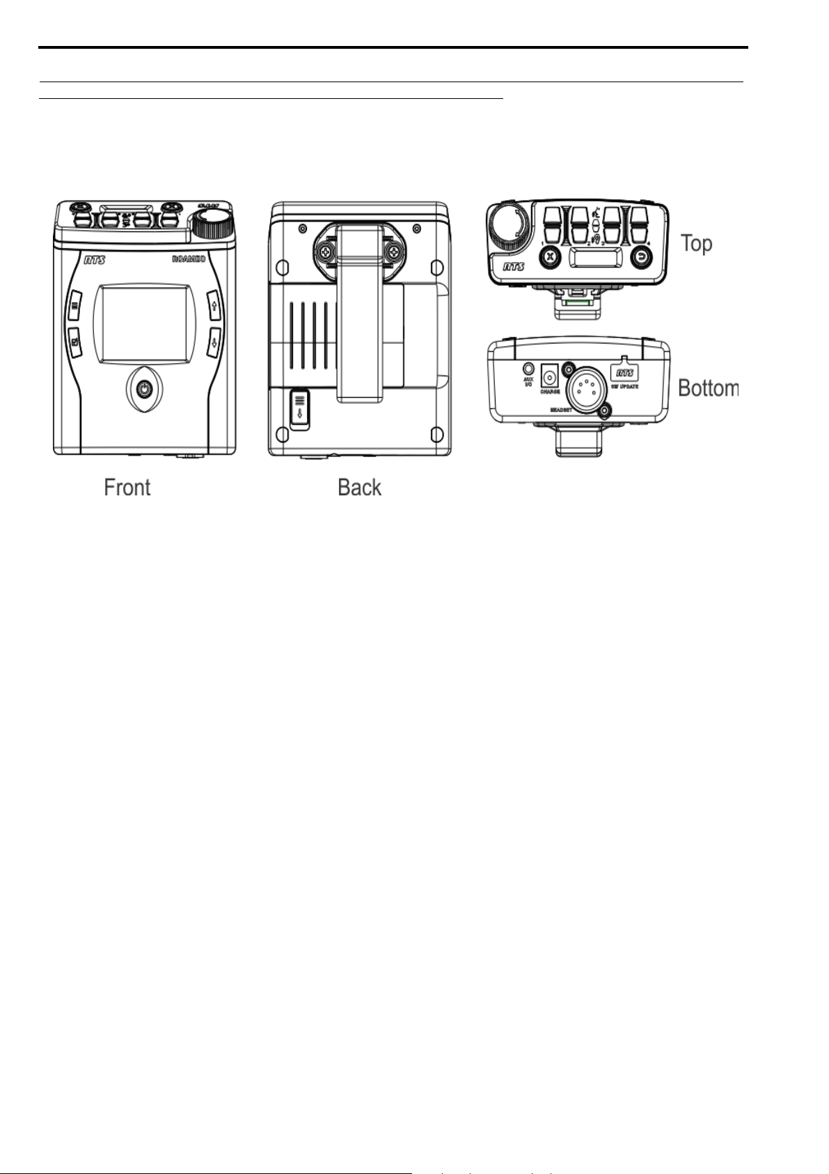
FIGURE 1. TR-1800 Reference View
1. Power button
2. Select button
3. Main Menu button
4. Color Backlit Display - 320 x 240 pixels
5. Scroll Up Navigation button
6. Scroll Down Navigation button
7. Battery Release slide
8. Removable Beltclip
9. Volume knob/Selection button
10. Call Waiting Clear button
11. Talk/Listen Buttons: Four channel sets
12. Talk/Listen indicator icons
13. Call Waiting Reply button
14. Call Waiting Monochrome Backlit Display – 128x32 pixels
15. USB Connector- No charging, just data
16. Headset Connector - standard 5-pin, female XLR connector
17. Charge Jack - accepts a 5.5 mm x 2.5 mm plug with the center positive. Must be supplied with a 12VDC regulated
power supply with at least 400 mA current capacity
18. Auxiliary Input/Headset Connector – 3.5 mm connector
Bosch Security Systems, Inc.
Technical Manual
F.01U.306.750
Rev. 01
Page 17
ROAMEO System Introduction 17
TR-1800 Connections
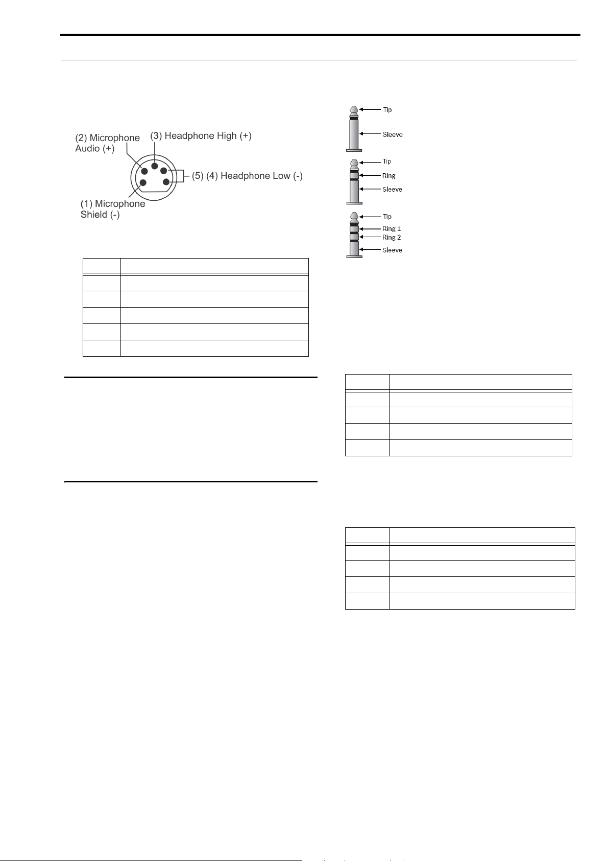
XLR - 5-Pin Female
FIGURE 2. XLR – 5-pin Female Connection
Pin Description
1Ground
2 Microphone
3 Headphone +
4 Headphone -
5 Headphone - (tied to pin 4)
3.5mm Auxiliary Jack
FIGURE 3. 3.5 mm Tip, Ring, Sleeve diagram
Accepts a 3.5mm TRS (Tip, Ring, Sleeve) stereo
connector or a mono TS (Tip, Sleeve)
NOTE: Audio can be input via the Tip, Ring 1 or
both.
IMPORTANT: Most XLR headsets use dynamic-type
microphones that work well with radiated
RF energy. However, some XLR headsets
use Electret microphones that are
susceptible to RF energy and may generate
audio noise. Always test any Electret type
headsets with the product before using to
troubleshoot any issues.
Description
Tip Audio Input
Ring 1 Audio Input
Ring 2 Ground
Sleeve Not Connected
Headset Mode
Accepts 3.5mm iPhone-like TRRS (Tip, Ring 1, Ring 2,
Sleeve) connector
Description
Tip Headphone -
Ring 1 Headphone +
Ring 2 Ground
Sleeve Microphone (+5VDC bias supplied)
Bosch Security Systems, Inc.
Technical Manual
F.01U.306.750
Rev. 01
Page 18

18 Introduction ROAMEO System
USB Jack - Type A
Pin Description
1 +5 (only powered in firmware download
process)
2 Data-
3 Data +
4 GND
Charging Jack
Accepts a 5.5mm x 2.5mm plug with positive center
Description
Center Accepts 12VDC
Shell GND
Bosch Security Systems, Inc.
Technical Manual
F.01U.306.750
Rev. 01
Page 19

ROAMEO System Introduction 19
TR-1800 Specifications
General:
Audio Modes
G.722 wideband mode
G.726 narrowband mode
Frequency Response (G.722)
165 Hz – 7.0 kHz
Frequency Response (G.726)
255 Hz – 3.6 kHz
Front Backlit Display
Color, 320 x 240 pixel, QVGA LCD
Top Backlit Display
Black and White, 128 x 32 pixel LCD
Removable Battery Pack
Li-Ion Pack, 7.5 VDC, 2300 mAhr
Typical Battery Life
17 hours
Environmental:
Operating Temperature
32°F – 122°F (0°C – 50°C)
Storage Temperature
-4°F – 158°F (-20°C – 70°C)
Dimensions (w/beltclip)
4.93 in. H x 4.00 in. W x 2.31 in. D
(12.51 cm H x 10.16 cm W x 5.87 cm D)
Dimensions (w/o beltclip)
4.93 in. H x 4.00 in. W x 1.85 in. D
(12.51 cm H x 10.16 cm W x 4.70 cm D)
Weight (w/ battery)
0.771 lbs. (350 g)
Weight (w/o battery)
0.507 lbs. (230 g)
Controls:
Level Controls
Top-mounted rotary encoder
Individual listen adjustment
Talk/Listen Control
4 x Talk and 4 x Listen buttons (top panel)
Number of Assignment Pages
4
Call Waiting Control
Reply and Clear buttons
Menu Settings Control
Menu, Set, Up, and Down buttons
Connections:
Headset Connectors
XLR-5F
3.5mm (iPhone type)
Headphone Impedance (both XLR and 3.5mm)
51 – 2000
Microphone Type (XLR Jack)
Dynamic or Electret auto-detect
Microphone Type (3.5mm Jack)
Electret only (+5V bias always supplied)
In-beltpack Charging Jack
Accepts 2.5 x 5.5mm charging plug, positive center
In-beltpack Charging Jack Voltage/Current
12VDC @ 400mA
Auxiliary Audio Input Jack
3.5mm for MP3 type audio input
Only fed to local headset
Firmware Update Jack
USB Type A
RF Communications:
Frequency Range
1880 – 1900 MHz (EU - Europe, Asia, and Australia)
1920 – 1930 MHz (NA - North America)
Communication Protocol
DECT
Carrier Frequency Selection
Automatic via DCS (Dynamic Channel Selection)
Modulation
GFSK
Maximum Output Power (Peak)
200 mW (EU)
100 mW (NA)
Average Power (G.722 wideband)
17 mW (EU)
Average Power (G.726 narrowband)
8 mW (EU)
Average Power (G.722 wideband)
8 mW (NA)
Average Power (G.726 narrowband)
4 mW (NA)
TR-1800 Beltpack Case
(includes removable and adjustable shoulder strap)
Dimensions
4 in. x 1.5 in. x 4.5 in.
(101.6 mm x 38.1 mm x 114.3 mm)
Certifications
RoHS, FCC part 15D, FCC part 15B, FCC/IC Class
B device, IC RSS-213, IC ICES-003, CE, EN 301
406, EN 301 489-6, EN 60950-1, RCM, Singapore,
Mexico
Bosch Security Systems, Inc.
Technical Manual
F.01U.306.750
Rev. 01
Page 20
20 Introduction ROAMEO System
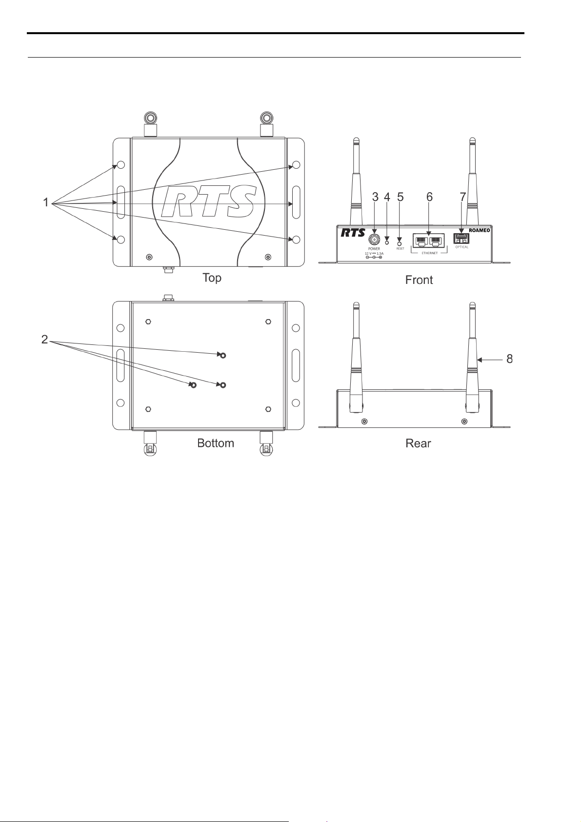
AP-1800 Reference View
FIGURE 4. AP-1800 Reference View
1. Mounting Tabs
2. Mounting Holes (for use with optional Clamp Kit)
3. Power Connector
4. Power LED Indicator (for more information, see
“AP-1800 Specifications” on page 22)
5. Reset Button
6. Ethernet Connector (x2)
7. Optical Connector (Accepts small form factor
pluggable SFP modules)
8. Antenna (x2)
Bosch Security Systems, Inc.
Technical Manual
F.01U.306.750
Rev. 01
Page 21

ROAMEO System Introduction 21
AP-1800 Connections
Dual Ethernet Connectors
Pin Description
1 Data 1 +
2 Data 1 -
3 Data 2 +
4 Data 3 +
5 Data 3 -
6 Data 2 -
7 Data 4 +
8 Data 4 -
Fiber Optic Connector
Accepts small Form Factor Pluggable (SFP) transceivers
• SM (Single Mode) SFP Module (F.01U.278.502)
• MM (Multi Mode) SFP Module (F.01U.278.503)
Power Connector
Accepts a screw-on, locking 5.5mm x 2.5mm x 13.8mm plug
with positive center.
Center – Accepts 12VDC @ 1.5A
Shell – GND
Antenna Connector
Reverse-polarity SMA Female Jack (R-SMA-F)
Bosch Security Systems, Inc.
Technical Manual
F.01U.306.750
Rev. 01
Page 22

22 Introduction ROAMEO System
AP-1800 Specifications
General:
Audio Modes
G.722 wideband
G.726 narrowband
Max. beltpacks per AP-1800 (G.722)
5
Max. beltpacks per AP-1800 (G.726)
10
Connectivity
Standard 100Base-T or GigE Ethernet
Protocol Running on Ethernet
OMNEO
Ethernet Cabling Required
UTP CAT-5e or better
Power Supply Type
External DC, Wall Wart
Power Supply Input
100–240 VAC, 50–60 Hz, 0.6A
Power Supply Output (AP-1800 Input)
12VDC @ 1.5A, positive center
Environmental
Operating Temperature
32°F – 122°F (0°C – 50°C)
Storage Temperature
-4°F – 158°F (-20°C – 70°C)
Dimensions
5.17 in. H x 7.67 in. W x 1.52 in. D
(13.13 cm H x 19.47 cm W x 3.86 cm D)
Weight (w/antennas)
0.992 lbs. (450 g)
Weight (w/o antennas)
0.893 lbs.(405 g)
Connections:
Ethernet Connectors
2 x Standard RJ-45 Jacks
Optical Connector
Accepts small form factor pluggable SMP modules
RF Connectors
Reverse-SMA-F
RF Communications:
Frequency Range
1880-1900 MHz (EU - Europe, Asia, Australia)
1920-1930 MHz (NA - North America)
Communication Protocol
DECT
Carrier Frequency Selection
Automatic via DCS (Dynamic Channel Selection)
Modulation
GFSK
Power
Maximum Output Power (Peak)
200mW (EU)
100mW (NA)
Average Power, load dependent (G.722, wideband)
17-83mW (EU)
Average Power, load dependent (G.726, wideband)
8-83mW (EU)
Average Power, load dependent (G.722, wideband)
8-42mW (NA)
Average Power, load dependent (G.726, narrowband)
4-42mW (NA)
Antenna - Electrical
Frequency
1850-1990MHz
Gain
3dBi
Horizontal Beam Width
360°
Impedance
50 Ohm
Max. Power
50W
VSWR
<2:1
Polarization
Linear - along length of antenna
Antenna - Mechanical
Weight
0.77 oz (22g)
Length
5.2 in. (133mm)
Max. Diameter
0.52in. (13.2mm)
Finish
Matte Black
Connector
Reverse Polarity SMA Plug
Operating Temperature
-40°F to 131°F (-40°C to 55°C)
AP-1800 Certifications
RoHS, FCC Part 15D, FCC Part 15B, FCC/IC Class B
device, IC RSS-213, IC ICES-003, CE, EN 301 406, EN
301 489-6, EN 60950-1, RCM, Singapore, Mexico
Bosch Security Systems, Inc.
Technical Manual
F.01U.306.750
Rev. 01
Page 23

ROAMEO System Introduction 23
Frequencies Of Operation
1880 – 1900 MHz (Europe)
1920 – 1930 MHz (North America)
ETSI Defined RF Channels for DECT
DECT systems automatically select the best interference-free frequencies on which to operate. Users do not need to do any
frequency coordination. The ETSI (European Telecommunications Standards Institute) Channel Plan (Table 1) shows the
European and North American RF carrier pools the DECT systems use.
There are 10 frequencies in Europe and five frequencies in North America.
TABLE 1. ETSI* defined RF Channels for DECT
RF Carrier Number Carrier Frequency, MHz Where Used
0 1897.344** Europe, Singapore, Australia
1 1895.616** Europe, Singapore, Australia
2 1893.888** Europe, Singapore, Australia
3 1892.160** Europe, Singapore, Australia
4 1890.432** Europe, Singapore, Australia
5 1888.704** Europe, Singapore, Australia
6 1886.976** Europe, Singapore, Australia
7 1885.248** Europe, Singapore, Australia
8 1883.520** Europe, Singapore, Australia
9 1881.972** Europe, Singapore, Australia
23 1921.536 US, Canada, Mexico
24 1923.264 US, Canada, Mexico
25 1924.992 US, Canada, Mexico
26 1926.720 US, Canada, Mexico
27 1928.448 US, Canada, Mexico
* ETSI (European Telecommunications Standards Institute)
** Most common carriers used in the world
Bosch Security Systems, Inc.
Technical Manual
F.01U.306.750
Rev. 01
Page 24

24 Introduction ROAMEO System
Bosch Security Systems, Inc.
Technical Manual
F.01U.306.750
Rev. 01
Page 25

CHAPTER 3
System Overview
System Description
A ROAMEO wireless intercom system consists of two types of devices: a wireless beltpack (TR-1800) and an access point
(AP-1800).
The ROAMEO system can be configured for anything from small systems (one access point and a few beltpacks) to a large
system (10 access points and up to 40 beltpacks). The ROAMEO system provides quality, configurable wireless audio across
the coverage area and is easily expandable.
The typical indoor coverage area varies widely depending on the installation area. The typical range of an access point is
between 50–100 meters.
System Considerations
• Number of access points required for coverage area.
• Sufficient access point coverage overlap to allow seamless roaming for beltpacks.
• The number of access points to provide sufficient capacity for all beltpacks planned to be in the area. It is especially
important to consider the number of beltpacks that are booted in the same area (and then moved to other areas). The
initial beltpack staging area should be able to provide access to all devices.
• Area Considerations
• Metal Barriers - Signal reflects off metal which can provide good signal fill for areas; however, the
signal will not pass through metal.
• Cement - Signal usually passes through with little problem. Dependent on the cement thickness
and the presence of any metal rebar.
• Wood and Drywall - No issues.
• Overall Size - May need more access points to cover a large area even if only a few beltpacks are
used.
• Spectrum Bandwidth - Other DECT systems in the area (i.e., wireless phone systems use some of the DECT
spectrum allowing less beltpacks in the area).
• Matrix system supports enough OMNEO channels for the amount of beltpacks.
• Ethernet infrastructure supports access points with sufficient bandwidth for additional traffic and uses managed
switches (OSI Layer 3 capable).
Bosch Security Systems, Inc.
Technical Manual
F.01U.306.750
Rev. 01
Page 26
26 System Overview ROAMEO System
Access Points
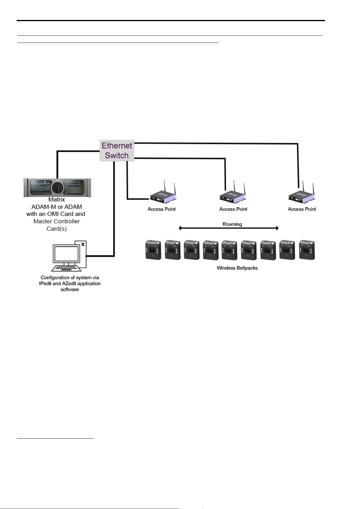
The ROAMEO AP-1800 converts DECT signaling to the OMNEO protocol, Audinate’s Dante digital high-quality audio
transport over IP. AP-1800 units are physically connected via the Ethernet network to an ADAM or ADAM-M matrix using
an OMI card
between the OMI card and the beltpack communicating via DECT.
There are two types of access points in a ROAMEO system:
1
. The OMI card maintains a bi-directional OMNEO channel for each beltpack. The AP-1800 acts as the interface
• Home AP
• Vis i tor AP
FIGURE 5. Components of a ROAMEO System
Home AP
The Home AP is any AP-1800 that configures the beltpack’s BPID (Beltpack ID) to one of its available OMNEO channels
using IPedit.
Visitor AP
The Visitor AP is any AP-1800 that does not configure the BPID to one of the its OMNEO channels in IPedit. The Visitor AP
can be thought of as a bridge that allows the visiting beltpack to communicate within the system while outside of its Home AP
radius (Figure 6).
NOTE: The Home and Visitor labels are in reference to the beltpack. A beltpack’s Home access point could be a Visitor
access point to a different beltpack.
1. For more information on OMI, see the OMI manual at www.rtsintercoms.com
Bosch Security Systems, Inc.
Technical Manual
F.01U.306.750
Rev. 01
Page 27
ROAMEO System System Overview 27
Roaming
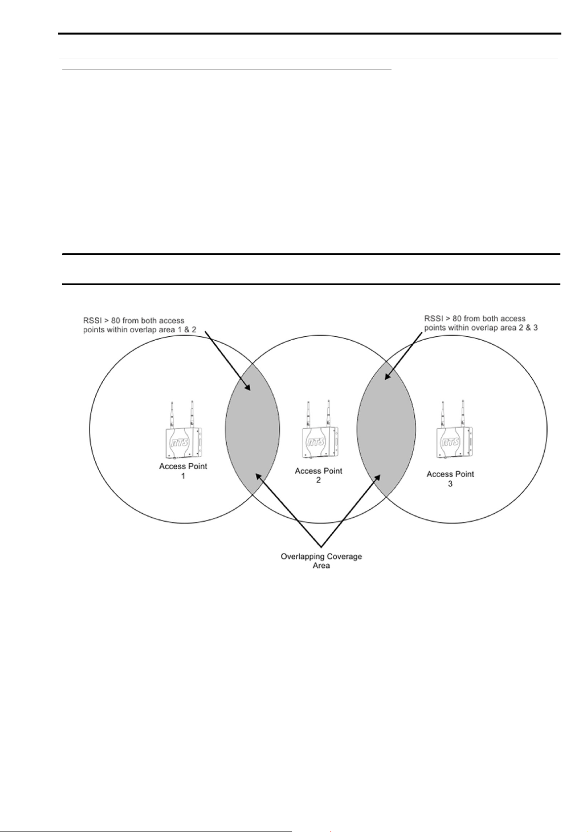
The ROAMEO system allows beltpacks to move between the radio coverage area of one AP-1800 to the radio coverage area
of another AP-1800. This is called roaming. Roaming is monitored and maintained by the system of access points, making it
transparent to the user. Handoff from one coverage area to another is done in such a way to make it nearly seamless. Roaming
does not involve any processing on the OMI, allowing the OMNEO bit stream to be completely uninterrupted.
In order for seamless hand-off to occur, the AP-1800 RF coverage area must overlap. This allows the beltpack handoff
commands to be sent to both the current access point and the new access point in the coverage area which ensures a seamless
hand-off.
The 80 RSSI (Received Signal Strength Indicator) contour line shown in Figure 6 is a number related to the access point’s RF
signal strength as received at the beltpack. This can be measured using the beltpack’s site survey screen when testing an access
point location. For more information, see “Site Survey” on page 39.
IMPORTANT: When there is little or no coverage overlap, a beltpack can experience undesirable audio break-up before
the hand-off to a new access point occurs.
FIGURE 6. SimpleFigure 6 Roaming Diagram
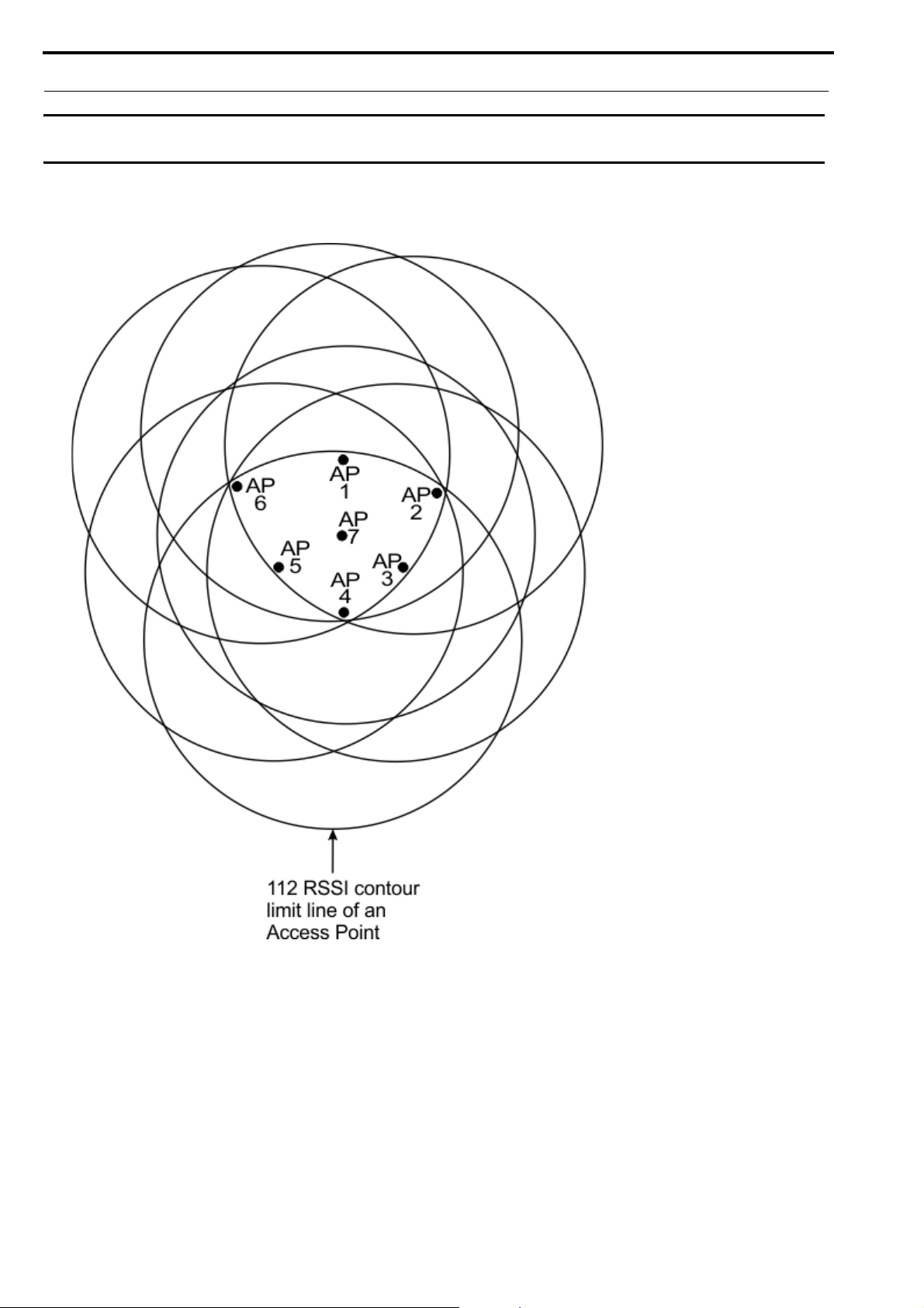
When access points boot, they scan the area and pick an RF carrier and time slot based upon the other beacons detected in the
area. The access points also avoid using carriers and time slots already in use by using AP IDs (access point identification).
Each access point in a system has to be set to a unique AP ID using the IPedit application. An algorithm based upon the AP ID
of the access point forces access points to never select the same carrier and slots.
In high density beltpack areas where more than six wideband access points may be required, some access points may not
detect an RF carrier already in use, that can result in roaming issues. The system works best if these scenarios are avoided by
designing high density areas with good access point overlap. Figure 7 shows how all seven access points can detect and
coordinate carriers and time slots with each other, even when there are more than six devices present. The 112 RSSI contour
line can be measured by a beltpack using the site survey screen when testing an access point location. See “Perform a Site
Survey” on page 46.
Bosch Security Systems, Inc.
Technical Manual
F.01U.306.750
Rev. 01
Page 28
28 System Overview ROAMEO System
IMPORTANT: It is important if more than six wideband or ten narrowband access points are used to cover the same
area that all the access point be placed in a location where they can detect each other.
FIGURE 7. High Density Roaming
Bosch Security Systems, Inc.
Technical Manual
F.01U.306.750
Rev. 01
Page 29
ROAMEO System System Overview 29
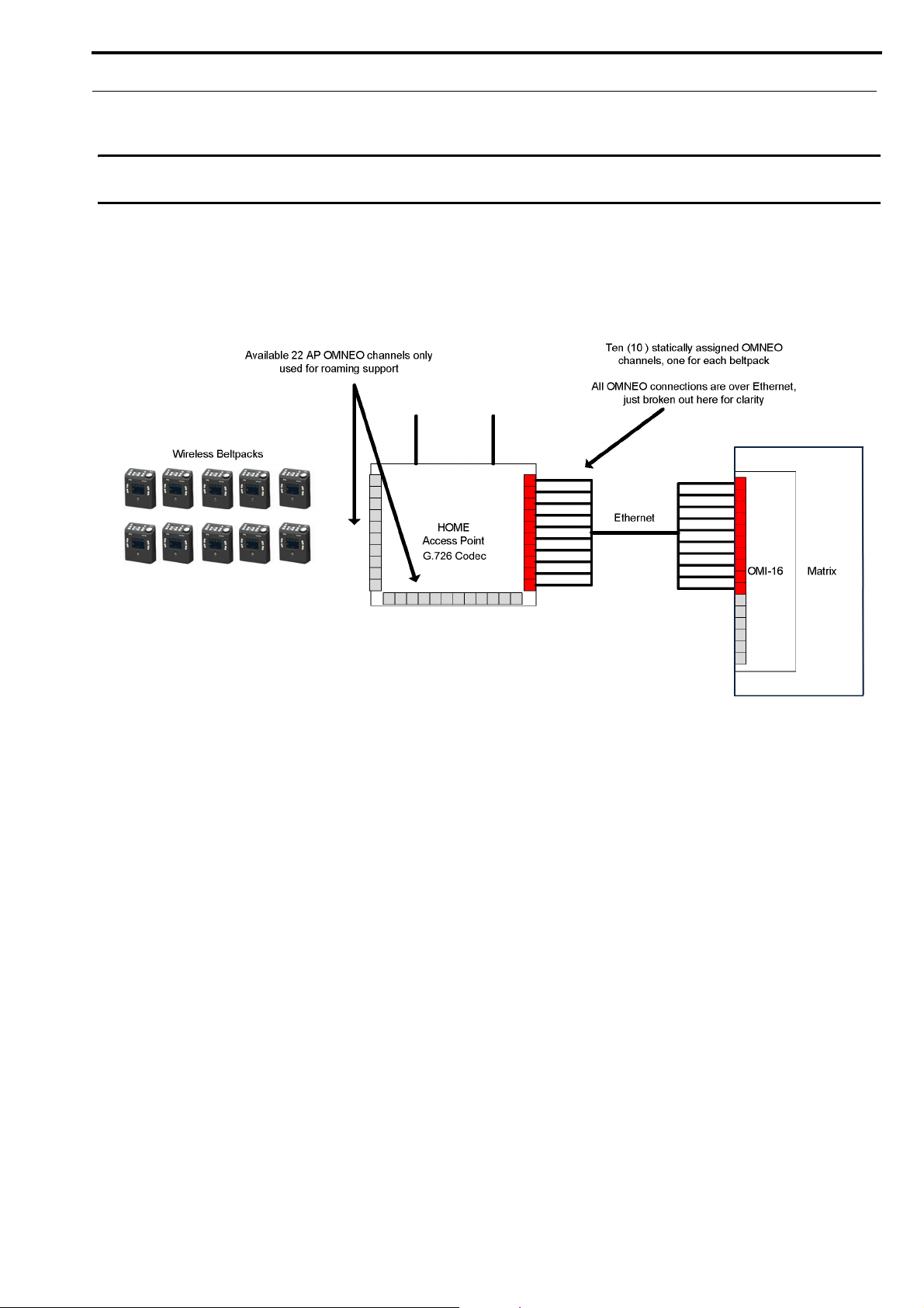
Home Connections
IMPORTANT: When configuring home connections, remember to assign the configured access point channels to the
OMI card in the Matrix (see “Connecting the Access Point to the Intercom” on page 59).
Each access point channel is a bi-directional OMNEO channel for audio, command, and control with the matrix. For a
wideband system (CODEC G.722), there are five access point channels available to assign BPIDs. For a narrowband system
(CODEC G.726), there are 10 access point channels available. The OMNEO channel that returns to the OMI from the Home
access point
FIGURE 8. Home Access Point to Matrix System Drawing
Bosch Security Systems, Inc.
Technical Manual
F.01U.306.750
Rev. 01
Page 30
30 System Overview ROAMEO System
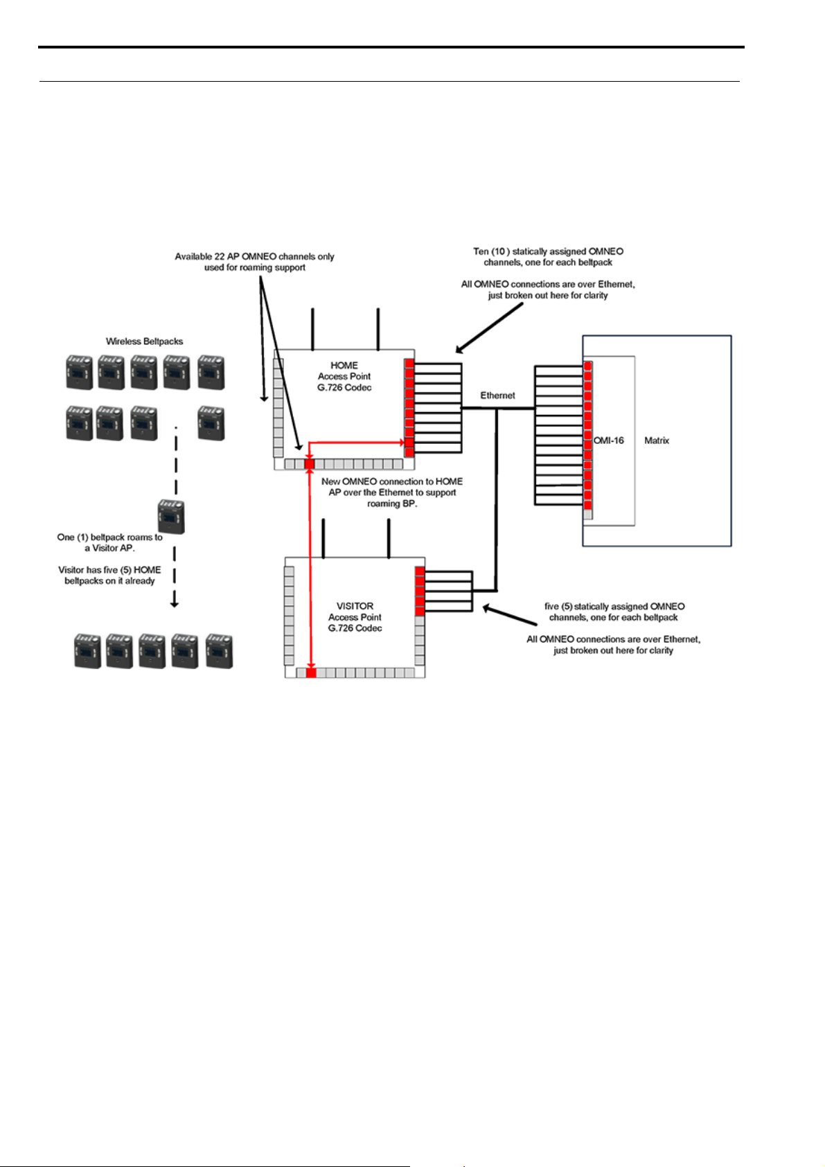
Home to Visitor Roaming
When a beltpack roams from its Home AP to a Visitor AP, a new OMNEO connection is made between both access points.
However, before the new connection’s OMNEO channel is used, the new DECT RF connection must be confirmed as good.
The new DECT RF connection is made before breaking from the old connection. This means the existing DECT RF link to the
Home AP is maintained until the new DECT RF link to the Visitor AP is confirmed. When the connection is confirmed, the
existing DECT RF link is dropped and the new OMNEO channel from the Visitor AP is used.
FIGURE 9. Home Access Point to Visitor Access Point Roam System Drawing
Bosch Security Systems, Inc.
Technical Manual
F.01U.306.750
Rev. 01
Page 31

ROAMEO System System Overview 31
System Drawings
These following drawings are basic examples of small, medium and large ROAMEO systems
Small System
FIGURE 10. Small System – G.722 Coverage for a Remote Area
Bosch Security Systems, Inc.
Technical Manual
F.01U.306.750
Rev. 01
Page 32

32 System Overview ROAMEO System
FIGURE 11. Small System – G.726 Coverage for a Single Area
Bosch Security Systems, Inc.
Technical Manual
F.01U.306.750
Rev. 01
Page 33

ROAMEO System System Overview 33
FIGURE 12. Small System – G.722 Coverage over Two Areas
Bosch Security Systems, Inc.
Technical Manual
F.01U.306.750
Rev. 01
Page 34

34 System Overview ROAMEO System
Medium System
FIGURE 13. Medium System – G.722 Coverage Over Two Areas and Between
Bosch Security Systems, Inc.
Technical Manual
F.01U.306.750
Rev. 01
Page 35

ROAMEO System System Overview 35
FIGURE 14. Medium System – G.726 Coverage Over One Large Area
Bosch Security Systems, Inc.
Technical Manual
F.01U.306.750
Rev. 01
Page 36

36 System Overview ROAMEO System
Large System
FIGURE 15. Large System – G.722 Coverage Over Three Areas
Bosch Security Systems, Inc.
Technical Manual
F.01U.306.750
Rev. 01
Page 37

ROAMEO System System Overview 37
FIGURE 16. Large System – G.726 Coverage Over One Large Area
Bosch Security Systems, Inc.
Technical Manual
F.01U.306.750
Rev. 01
Page 38

38 System Overview ROAMEO System
ROAMEO System Setup Checklist
❐
❐
❐
❐
❐
❐
❐
❐
❐
❐
Each beltpack has only one HOME access point.
Each system can have only one Sync Master access point (set in IPedit).
When subscribing a beltpack to the system, the beltpack must be within 40 feet (12 meters) of an access point in
that system.
Each access point set to the G.722 CODEC can be a host for up to five beltpacks (no channels left for roaming
beltpacks).
Recommend each G.722 access point only be loaded to four beltpacks to allow for roaming beltpacks.
Each access point set to the G.726 CODEC can be host for up to 10 beltpacks (no channels left for roaming
beltpacks).
Recommend each G.726 access point only be loaded to eight beltpacks to allow for roaming beltpacks.
If the CODEC is changed for a system, the beltpacks must be subscribed again.
A system can only have all G.722 or all G.726 access points (no CODEC mixing is allowed).
Always have Ethernet connected to an access point before powering up the access point.
❐
❐
❐
❐
❐
❐
❐
❐
❐
The Ethernet network follows standard Ethernet practices.
Use only CAT5e UTP or better Ethernet cable.
Use only Layer 3 IP routing-capable, managed switches.
100Mbit networks can only have up to seven hops (A link between the Matrix and an Ethernet switch counts as a
hop, each link after daisy chaining through an access point counts as a hop).
1GBit networks can only have up to 20 hops (A link between the Matrix and an Ethernet switch counts as a hop,
each link after daisy chaining through an access point counts as a hop).
Maximum system size is 10 access points and 40 beltpacks.
The overlap RF coverage area between two adjacent access points should have an RSSI reading of 80 or better
from each access point for error free roaming.
In a high density beltpack coverage area with more than six access points (G.722) or more than 10 access points
(G.726) covering the area, all access points must be within each other’s -70dBm RF coverage contour (112 or
better on the beltpack’s RSSI site survey screen).
If a PoE adapter is used, access points cannot be daisy-chained. Only one access point can be powered from the
PoE adapter. For more information, see “Power Over Ethernet” on page 57.
Bosch Security Systems, Inc.
Technical Manual
F.01U.306.750
Rev. 01
Page 39

CHAPTER 4
Site Survey
Description
Site Survey is the application (standard on the TR-1800) used to plan and design the ROAMEO system. Site survey provides
crucial information on roaming coverage. With the ROAMEO site survey application, finding coverage areas for access
points, even when obstacles are encountered, such as metal walls, reinforced concrete, metal-coated glass, etc. is easier to
accomplish.
There are two ways to perform a site survey:
• With a Static IP Address
• With a Dynamic IP Address
Set Up Site Survey
With a simple setup, site survey can be used and evaluated.
Requirements
Required equipment for a simple setup:
• AP-1800 access point and power supply
• TR-1800 beltpack and battery
• Computer with an Ethernet port and IPedit software application installed
• Standard Ethernet cable
Prepare the Hardware
1. Install the antennas on the access point (see “Antenna connection and placement ” on page 51).
2. If performing a site survey without a matrix, use an Ethernet cable to connect the AP-1800 to the computer.
OR
If performing a site survey with a matrix, use an Ethernet cable to connect the AP-1800 to the network.
Bosch Security Systems, Inc.
Technical Manual
F.01U.306.750
Rev. 01
Page 40

40 Site Survey ROAMEO System
Set Up an Existing System with a Static IP Address
To set the computer to a Link Local IP Address, do the following:
IMPORTANT: These instructions detail a typical setup for the Windows 7 platform.
NOTE: If the AP-1800 has been connected to a Matrix system in the past or assigned a static IP Address already, then
assigning the computer a Link Local Address will not work. If the AP-1800’s IP Address is known, configure the
computer to be in its network. If the IP Address is unknown, then reset the AP-1800 back to a Link Local
Address by performing a factory reset, see “Factory Default Reset” on page 144.
1. From the Start menu, select Control Panel.
2. Click Network and Internet.
The Network and Internet window appears.
Bosch Security Systems, Inc.
Technical Manual
F.01U.306.750
Rev. 01
Page 41

ROAMEO System Site Survey 41
3. Click Network and Sharing Center.
The Network and Sharing Center window appears.
4. Click Change Adapter Settings.
The Network Connections window appears.
5. Double-click Local Area Connection.
The Local Area Connection Status window appears.
Bosch Security Systems, Inc.
Technical Manual
F.01U.306.750
Rev. 01
Page 42

42 Site Survey ROAMEO System
6. Click Properties.
The Local Area Connection Properties window appears.
7. From the connection list, select Internet Protocol Version 4 (TCP/IPv4).
Bosch Security Systems, Inc.
Technical Manual
F.01U.306.750
Rev. 01
Page 43

ROAMEO System Site Survey 43
8. Click the Properties button.
The Internet Protocol Version 4 (TCP/IPv4) Properties window appears.
9. Select the Use the following IP Address check box.
The IP fields become active.
10. In the IP Address: field, enter 169.254.0.1.
11. In the Subnet mask: field, enter 255.255.0.0.
12. Click the OK button to exit the Internet Protocol Properties window.
13. Click the Close button to exit the Local Area Connection Properties window.
Add the Access Point to IPedit
To add the access point to IPedit, do the following:
1. Power on the access point.
When the power light turns solid green, the access point is ready.
2. Open IPedit.
Bosch Security Systems, Inc.
Technical Manual
F.01U.306.750
Rev. 01
Page 44

44 Site Survey ROAMEO System
3. From the Device menu, select Add.
The Add Devices window appears.
4. Select the access point (displays as the device type OAP-5 or OAP-10).
5. Click Add.
The access point appears in the Device Catalog in the left pane.
6. Click Done.
Assign the TR-1800 to an AP-1800 Channel
To assign the TR-1800 to an AP-1800 channel, do the following:
1. From the Device Catalog on the left, select the AP-1800.
The Device Information fields populate.
2. Select the Sync Master check box to set the AP-1800 to Sync Master.
IMPORTANT: On a piece of paper, note the 3-digit System ID (the default is B2B) and the 4-digit PIN (the default is
0000) of the access point. These are used later to subscribe the beltpack to the access point.
3. Power up the TR-1800.
The BPID displays on the front panel. This is a 10-digit, hexadecimal number (for example, 00:09:22:B5:21).
4. In the DECT BPID field, enter the beltpack ID to assign to that channel.
5. From the Changes menu, select Send All.
The Send Changes window appears.
6. Click OK.
The changes are sent to the AP-1800 and then it resets. After approximately one minute, the Sync check box turns
green. The AP-1800 stores the BPID, even if power is disconnected (for example, in non-volatile memory).
Subscribe the TR-1800 to the AP-1800
To subscribe the TR-1800 to the AP-1800, do the following:
IMPORTANT: Be sure the beltpack is within 40 feet (12 meters) of the AP-1800.
1. With the AP-1800 running, power up the TR-1800.
The front color display panel activates.
2. Press the Menu button.
The beltpack main menu appears.
Bosch Security Systems, Inc.
Technical Manual
F.01U.306.750
Rev. 01
Page 45

ROAMEO System Site Survey 45
3. Using the up and down arrow buttons, navigate to the System Setup icon.
4. Press the Select button.
The Subscription Setup screen appears with the system setup icon highlighted.
5. Press the Select button.
The Enter system ID screen appears.
NOTE: If the beltpack had been subscribed to an access point previously, the last system ID used populates the
screen. The default System ID is B2B.
6. Using the up and down buttons, enter the first character of the access point system ID.
7. Press the Select button.
The focus moves to the next character space in the system ID.
8. Repeat steps 8 and 9 until the system ID is entered completely.
9. Once the system ID is entered, press the Select button.
The Enter PIN screen appears.
10. Using the up and down buttons, enter the first digit of the access point pin number (The default is 0000).
11. Press the Select button.
The focus moves to the next character space in the system ID.
12. Repeat steps 12 and 13 until the system ID is entered completely.
The Home screen appears in the front display, the DECT connection icon and the RSSI indication icon become
active.
Bosch Security Systems, Inc.
Technical Manual
F.01U.306.750
Rev. 01
Page 46

46 Site Survey ROAMEO System
Set Up an Existing System with a Dynamic IP Address
IMPORTANT: The computer should be set to obtain an IP Address automatically. The DHCP server for the matrix
must be enabled in the AZedit application before the computer delivers an IP Address.
To connect the AP-1800 to the matrix, do the following:
1. Using an Ethernet cable, connect the AP-1800 to the Matrix directly or via a network switch.
2. Connect one end of the power supply to the AP-1800 and the other end to the wall outlet.
The AP-1800 powers on.
3. Using IPedit, configure the OMI card with the AP-1800 unit.
NOTE: If the AP-1800 being used is already part of an operating system and a TR-1800 is subscribed to it, then no
more IP configuration is required. Turn off all other AP-1800 devices in the system so coverage of the single
access point being tested can be found. For more information, see “Perform a Site Survey” on page 46.
For complete instructions on how to configure the AP-1800, see “Connecting the Access Point to the Intercom” on page 59.
Perform a Site Survey
A site survey is performed to determine the placement of access points to ensure RF coverage of the desired area. A beltpack,
communicating with an access point at a test location, is set to the site survey screen where RSSI (Received Signal Strength
Indication) and QF (Quality Factor) are both used to find the RF coverage area.
Pre-conditions
•
A beltpack has been successfully subscribed to an access point.
• A site map or blueprint of the building that can be marked up.
• Power can be supplied to the access point at the possible test locations either by using power extension
cables or battery power. For battery power, 12VDC @ 0.600 Amps must be available to the access
point. A charged 12VDC battery rated for at least 2.4 Amp-hours is recommended for a typical site
survey length of time. The input connector required for an access point is a 13.8mm long, female barrel,
2.5mm x 5.5mm connector.
IMPORTANT: The unit is marked 1.5 Amps. This is an upper limit set to handle peak loads when fully loaded. When
doing site surveys, an access point is not heavily loaded.
To perform a site survey, do the following:
1. Place the access point in the location to be tested for coverage.
2. Power up the access point.
When the power light turns to solid green, the access point is ready.
3. Power up the beltpack.
The splash screen momentarily displays and then the home screen appears.
NOTE: When the beltpack finishes booting, the home screen of the beltpack indicates a wireless
connection . If the wireless connection does not display, verify settings in the “Setup for a Site
Survey” section.
4. Press the Menu button.
The beltpack main menu appears.
Bosch Security Systems, Inc.
Technical Manual
F.01U.306.750
Rev. 01
Page 47

ROAMEO System Site Survey 47
5. Using the up and down arrow buttons, navigate to the System Setup icon.
6. Press the SELECT button.
The beltpack system setup menu appears.
7. Using the up and down arrow buttons, navigate to the Site Survey icon.
8. Press the SELECT button.
The site survey screen appears.
Description of Site Survey Screen
CARRIER - Current RF carrier of the access point (this may change from time to time)
SLOT - Current time slot on the RF carrier the access point to beltpack packets are on (this may change from time
to time)
AP ID - Access Point Identification
RSSI - Radio Signal Strength Indication
QF - Quality Factor. This is representative of the number of packets received out of packets sent
Description of RSSI
RSSI Color Description
0-47 Red Weak - poor to no reception in area
48-70 Yellow Marginal - some dropouts of audio in the area
71-216 Green Strong - good RF coverage
Bosch Security Systems, Inc.
Technical Manual
F.01U.306.750
Rev. 01
Page 48

48 Site Survey ROAMEO System
Description of QF
QF Color Description
0-4 Red Weak - too many dropouts in the area
5-6 Yellow Marginal - some dropouts of audio in the area
7-10 Green Strong - good RF coverage
9. Mark the access point’s location on the building layout diagram.
10. Walk around with the beltpack throughout the area(s) of interest while looking at the site survey screen.
NOTE: Record the RSSI and QF number on the building layout diagram at several locations throughout the area of
interest.
GOOD COVERAGE AREA DEFINITION
RSSI = 71-216, Site survey bar in the green.
QF = 7-10, Site survey bar in the green.
If the two indications are different, always use the worst case of the RSSI and QF
indication for defining a good coverage area. Example: QF =10 and RSSI=71, use the
RSSI level as the cutoff for the good coverage area.
NOTE: When enough data points are collected, draw a line on the building layout, using the coverage limits. If surveying
for roaming coverage, take note access point coverage is shown in Figure 6 on page 27.
Notes
• Try other access point locations to improve the RF coverage in the desired area, if needed.
• If setting up a roaming system, ensure a good overlap of coverage areas of the access points. Good
roaming between access point areas requires overlap of coverage for error free roaming.
• The access points that support roaming beltpacks should have an RSSI of >80 from each access point
involved in the overlap to provide error free roaming. See Figure 6 on page 27.
• In high beltpack density areas, where more than six access points on wideband (G.722) or more than 10
access points on narrowband (G.726) are required to provide coverage over the same area due to a larger
number of beltpacks, it is important the access points are located in good RF coverage of each other. In
these scenarios, the access points need to be within -70 dBm of each other. This translates to each
access point should be in a coverage area with an RSSI reading of 112 or better on a site survey. See
Figure 7 on page 28.
Bosch Security Systems, Inc.
Technical Manual
F.01U.306.750
Rev. 01
Page 49

Access Point Placement
Considerations
• Access Point Placement
• System Considerations - See System Drawings Chapter
• Mounting Options
• Mounting Surfaces
• Site Survey
CHAPTER 5
Installation
Access Point Placement
The placement of access points can be critical for optimal RF performance of the system. When positioning the access points,
place them in the best location for maximum, unimpeded coverage of the area. Installation of the access point should be high,
above the area of interest, on a truss or ceiling. Tilt the antennas so they are approximately 15° to 30°. The access point could
also be placed high on a vertical wall; in this case, the antennas should pointing straight up.
Site Survey
For more information, see “Site Survey” on page 39.
RF (Radio Frequency) Considerations
Keep antennas away from metal, as metal can detune them and distort the RF pattern. It is recommended to keep the antennas
at least 2λ (2 * wavelength) from any parallel metal object (about 30 cm/12 inches), not including metal trusses or metal roofs.
A metal roof, metal trusses, or the access point’s metal case become a reflector, offering advanced coverage by reflecting the
RF signal down to the intended area of coverage, which can improve coverage. Note, when mounting to drywall, be aware of
metal studs that can affect signal quality. Metal in walls can greatly attenuate or even block RF signals. In the case of a metal
wall, it may become necessary to place another access point on the other side of the wall if continued coverage is desired.
The polarization of the access point antennas should match the polarization of the beltpack’s internal antennas when worn on
the belt. The standard position of the antennas are vertical. This means the electrical field of the antennas is also vertical. For
best reception, the access point’s antennas should be in the vertical position, either straight up or straight down.
Bosch Security Systems, Inc.
Technical Manual
F.01U.306.750
Rev. 01
Page 50

50 Installation ROAMEO System
Mounting Options
FIGURE 17. Mounting Options
There are four recommended ways to mount the ROAMEO AP-1800 access point unit:
• Wall or ceiling mount
• pole mount
• rail mount
• free-standing installation (such as a table or shelf) – not shown above
IMPORTANT: The mounting clamp kit, for rail or pole mounting, is sold separately.
Bosch Security Systems, Inc.
Technical Manual
F.01U.306.750
Rev. 01
Page 51

ROAMEO System Installation 51
Antenna connection and placement
Antennas should be in the upright-most position for the best reception of signal. The antenna has a joint to adjust the angle, if
needed.
To attach the antennas to the ROAMEO AP-1800, do the following:
1. Gently push the antenna into the antenna connector on the ROAMEO AP-1800. Take care to align the connector
pin with the antenna pin hole.
2. Turn the antenna clockwise to tighten in place.
NOTE: For permanent antenna installation, we recommend tightening the antennas so they cannot come loose from
vibration or if bumped. Hand-tighten the antenna, then using needle-nose pliers, grasp the serrated metal
collar of the antenna and tighten about 1/16th inch (1.6 mm) more in the clockwise direction. This tightens
the connector to about 5 lbf-in (0.56 Nm), the specification for a solid connection.
Bosch Security Systems, Inc.
Technical Manual
F.01U.306.750
Rev. 01
Page 52

52 Installation ROAMEO System
To adjust the antennas for the best signal reception when the access point is mounted horizontally, do the following:
> Carefully bend the antenna 90° at the antenna joint until the antennas are aligned straight up or down.
Bosch Security Systems, Inc.
Technical Manual
F.01U.306.750
Rev. 01
Page 53

ROAMEO System Installation 53
Wall or Ceiling Mounting
To wall mount the ROAMEO AP-1800 access point, do the following:
1. Using the access point and a pencil, mark the four hole locations on the wall or ceiling.
NOTE: It may be necessary to predrill the holes or use screw anchors, depending on the material of the wall.
2. Align the AP-1800 in the position and placement desired.
3. Using a screw driver, drive the screws into the predefined holes.
Bosch Security Systems, Inc.
Technical Manual
F.01U.306.750
Rev. 01
Page 54

54 Installation ROAMEO System
Pole Mounting
To pole mount the ROAMEO AP-1800 access point, do the following:
1. Align the mounting clamp in the pole use position on the bottom of the AP-1800.
2. Using the supplied screws from the mounting kit, attach the mounting clamp to the AP-1800.
3. Fit the mounting clamp around the pole desired.
4. Once in position, use the adjustment knobs to tighten the clamp around the pole.
Rail Mounting
To rail mount the ROAMEO AP-1800 access point, do the following:
1. Align the mounting clamp in the rail use position on the bottom of the AP-1800.
Bosch Security Systems, Inc.
Technical Manual
F.01U.306.750
Rev. 01
Page 55

ROAMEO System Installation 55
2. Using the supplied screws from the clamp kit, attach the mounting clamp to the AP-1800.
3. Fit the mounting clamp around the rail.
4. Once in position, use the larger adjustment knob to tighten the clamp around the pole.
Free-Standing Installation
Setting the AP-1800 unit on a table or shelf is commonly referred to as free-standing installation. When free-standing
installation the AP-1800, it is important to remember to position the antenna perpendicular to the unit (antenna in the air) for
the best signal reception.
Bosch Security Systems, Inc.
Technical Manual
F.01U.306.750
Rev. 01
Page 56

56 Installation ROAMEO System
AP-1800 Mounting Surfaces
The ROAMEO AP-1800 Access Point can be mounted to many different surfaces. Using Table 2, determine the proper
mounting surface and mounting materials needed.
TABLE 2. Mounting Surfaces and Materials
Mounting Surface Materials Used Qty
Drywall
Drywall screws 4
Drywall anchors (as needed) 4
1/4-inch (max.) Flat washer (as needed) 4
Concrete
1/4-inch (max.) Concrete screws 4
Concrete anchors (as needed) 4
1/4-inch (max.)Flat washer (as needed) 4
Wood
1/4-inch (max.) Wood Screws 4
1/4-inch (max.) Flat washer (as needed) 4
Metal Surface
Rack Frame
Building Structure Member (roof trusses, etc)
1/4-inch (max.) Sheet metal screws 4
1/4-inch (max.) Flat washer (as needed) 4
OR
1/4-inch (max.) Self-tapping or Self-drilling sheet metal screws 4
OR
1/4-inch (max.) Machine Screw 4
Machine nut or drilled and tapped holes
1/4-inch (max.) Flat washer (as needed) 4
10-32 Rackmount Screws 2 to 4
1/4-inch (max.) Flat washer (as needed) 2 to 4
OR
10-32 Truss Head Rackmount Screws 2 to 4
1/4-inch (max.) U-bolts 4
1/4-inch (max.) Flat washers 4
1/4-inch (max.) Machine nuts 4
OR
See Metal Surface Mounting
Bosch Security Systems, Inc.
Technical Manual
F.01U.306.750
Rev. 01
Page 57

ROAMEO System Installation 57
Power Over Ethernet
The access point is tolerant of PoE (Power Over Ethernet) voltages on the Ethernet network, but cannot be powered by PoE
directly without an add-on accessory kit (see “Accessories and Replacement Parts” on page 155). The add-on accessory kit can
be used when combined with an existing PoE (802.3af) or PoE+ (802.3at) managed Ethernet switch to provide power to the
access point from the Ethernet network. Only one access point can be powered by this regulated Ethernet PoE splitter, due to
the power consumption of the access points.
PoE Splitter Recommendation
Output Power
Regulated 12VAC @ 1Amp
Power Cable
Most splitters have a 2.1 by 5.5mm terminated cable, however, for the AP-1800 input a long barrel 2.5x5.5mm
connector with the length of 13.8mm is required
PoE Type
PoE (IEEE 802.3af) and/or PoE+ (IEEE 802.3at)
Ethernet Port
1000Mbps Auto-Negotiating type
Bosch Security Systems, Inc.
Technical Manual
F.01U.306.750
Rev. 01
Page 58

58 Installation ROAMEO System
Power Up the AP-1800 Access Point
To connect and configure the access point to the matrix, do the following:
1. Using an Ethernet cable or an optical fiber cable, connect the access point to the Matrix via a network switch.
NOTE: Either Ethernet port can be used.
IMPORTANT: To use the fiber option on the AP-1800,. you must have the optional SFP fiber module installed. For
ordering information, see “Accessories and Replacement Parts” on page 155.
2. Connect one end of the power supply to the AP-1800 and the other end to the wall outlet.
The AP-1800 powers on.
NOTE: The connection to the access point should be screwed on tight for a locked connection.
Bosch Security Systems, Inc.
Technical Manual
F.01U.306.750
Rev. 01
Page 59

ROAMEO System Installation 59
Connecting the Access Point to the Intercom
The OMI card is configured using AZedit and IPedit; however, only IPedit can be used to configure the access point.
IMPORTANT: Verify the computer is connected to the same network as the Intercom Matrix frame.
Configure the OMI using AZedit
To configure the OMI to the Access Point using AZedit, do the following:
1. From the Status menu in AZedit, select I/O Cards.
The I/O Card Status window appears showing a list of installed cards.
2. Right-click the OMI card to configure to the AP-1800.
A pop-up menu appears.
3. From the pop-up menu, select OMNEO Configuration.
The OMNEO Configuration window appears.
4. From the OMNEO card drop down menu, select the slot number where the OMI card is located in the frame.
The device Name field auto-populates with the name of the device.
5. From the Local Channel drop down menu, select the channel to use to communicate to the AP-1800 across the
network.
NOTE: Channels not already configured to connect to another device appear with an asterisk (*) next to them.
6. In the Partner Device Name field, enter the name of the AP-1800 to communicate with or select the Browse icon to
select from a list of devices.
OR
In the Partner IP Address field, enter the IP Address of the device to make a connection.
This field auto-populates when the Device Name is selected.
7. From the Partner Device Type drop down menu, select the type of device to which the OMI card is connecting.
8. From the Partner Channel drop down menu, select the channel on the device to which the OMI communicates.
9. When finished, click Apply.
Apply sends all the changes to all the cards in the intercoms or click Cancel to discard all the changes made.
Bosch Security Systems, Inc.
Technical Manual
F.01U.306.750
Rev. 01
Page 60

60 Installation ROAMEO System
Add the OMI to the Device Catalog in IPedit
To add the OMI to IPedit, do the following:
1. Open IPedit.
2. From the Device menu, select Add.
The Add Devices Window appears, open to the Search tab.
3. Select the OMI card.
The Add button becomes active.
4. Click the Add button.
The OMI card appears in the device catalog in the left panel.
5. Click the Done button.
The Add Devices window closes.
Configure the OMI using IPedit
To configure the OMI using IPedit, do the following:
Using the Device Configuration and Status Pane
1. In the Device Name field, enter the device name.
Initially, OMI cards are given a default name.
IMPORTANT: Changing the device name causes the device to reboot. It is not necessary to change the device name.
However, if changed, it is best to do this early in the setup so revisiting other devices that connect to this
device and updating them later is not necessary.
2. In the Description field, enter a description for the OMI card, if desired.
Using the Channel Configuration and Status Pane
3. In the Channel Description field, enter a channel description, if applicable.
4. From the Destination Type drop down menu, select OAP-5 or OAP-10.
NOTE: The Destination Type does not need to be selected if using the Browse window to select the device. It fills
the Type and IP Address automatically. The type is either OAP-5 (OMNEO Access Point - 5 Channel) or
OAP-10 (OMNEO Access Point - 10 Channel) depending on the CODEC configured on the device.
5. In the Destination Device Name field, enter the name of the device to which the channel will connect.
OR
Click the ... button.
The Discovered Devices Window appears.
a. Expand the tree to view the destination devices available.
b. From the expanded tree, select the destination device.
c. Click OK.
6. From the Destination Channel drop down menu, select the channel to which the OMI will connect.
7. Send the changes to the OMI.
Bosch Security Systems, Inc.
Technical Manual
F.01U.306.750
Rev. 01
Page 61

ROAMEO System Installation 61
Add the AP-1800 to IPedit
1. Start IPedit.
2. From the Devices menu, select Add.
The Add Devices window appears.
3. From the Available Devices pane, select the Access Point.
The Add button becomes active.
4. Click Add.
The AP-1800 appears in the device catalog in the left panel.
5. Click Done.
The Add Devices window closes. The AP-1800 appears in the Device Catalog.
Bosch Security Systems, Inc.
Technical Manual
F.01U.306.750
Rev. 01
Page 62

62 Installation ROAMEO System
Configure the AP-1800 in IPedit
To configure the Access Point with IPedit, do the following:
IMPORTANT: The user must be signed in to IPedit with network administrator rights to complete these instructions.
1. From the Device Catalog on the left, select the AP-1800.
The Device Information pane populates.
2. In the Description field, enter a unique description for the access point.
3. In the Version field, verify the version information is correct.
4. Verify the IP Address is correct, if using a Static IP Address.
5. Select the Disable RSTP check box to disable the RSTP protocol, if desired.
DECT Information
6. In the System ID field, enter the system ID for the access point. This field accepts a 3-digit hexadecimal number. By
default, this field is set to B2B.
NOTE: All access points in a system must have the same System ID.
7. In the AP ID field, enter the unique AP ID for the access point. The range for this field is 1–254.
8. Select the Sync Master check box if the access point is the master for the entire system.
NOTE: There can be only one master in each system.
Bosch Security Systems, Inc.
Technical Manual
F.01U.306.750
Rev. 01
Page 63

ROAMEO System Installation 63
9. In the PIN field, enter the PIN of the access point. By default, this field is set to 0000.
10. From the Zone drop down menu, select the zone the access point is assigned. By default the zone is set to 0
11. From the CODEC drop down menu, select the CODEC the access point is running.
IMPORTANT: The CODEC of the access point is either G.722 (wideband) or G.726 (narrowband) A system MUST be
all G.722 or all G.726
Channel Configuration Pane
12. From the column headings, select the channel to configure (for example, Channel 1, etc).
IMPORTANT: With CODEC G.722, five channels are available for configuration.
With CODEC G.726, 10 channels are available for configuration.
TIP: When setting up a multiple access point system, consider leaving one or two channels open for additional
beltpacks and distribute the existing beltpacks equally among the access points.
13. In the Channel Description field, enter a channel description, if applicable.
14. From the Destination Type drop down menu, select the OMI card to which the channel is connected.
Bosch Security Systems, Inc.
Technical Manual
F.01U.306.750
Rev. 01
Page 64

64 Installation ROAMEO System
15. In the Destination Device Name field, enter the name of the OMI card to which the channel is connected.
OR
Click the browse button.
The Discovered Devices window appears.
a. Expand the tree to view the available destination devices.
b. From the expanded tree, select the destination device.
c. Click OK.
The Discovered Devices window closes.
16. From the Destination Channel drop down menu, select the destination channel to which the channel is connected.
17. In the DECT BPID, enter the beltpack ID to assign to that channel.
NOTE: For information on obtaining the beltpack ID, see “Configure the Beltpack to its Home AP-1800” on
page 65.
18. In the DECT Zone Selections field, enter the zone the beltpack is permitted to operate in (the default is zone one).
OR
From the DECT Zone drop down menu, select the check box next to each zone to assign to the beltpack.
NOTE: At least one zone must be selected for the beltpack. Any combination of zones may be selected.
19. From the Changes menu, select Send.
20. From the File menu, click Save.
Bosch Security Systems, Inc.
Technical Manual
F.01U.306.750
Rev. 01
Page 65

ROAMEO System Installation 65
Configure the Beltpack to its Home AP-1800
To assign a beltpack to an access point channel, do the following:
1. From the Device Catalog on the left, select the AP-1800.
The Channel Configuration populates.
2. Power up the beltpack.
The BP ID displays on the front panel. This is a 10 digit, hexadecimal number in the format of: BP00:09:XX:XX:XX.
3. In the DECT BPID, enter the beltpack ID to assign to that channel.
4. From the Changes menu, select Send Changes.
The Send Changes window appears.
5. Click OK.
The changes are sent to the access point. The AP stores the BPID even if power is disconnected.
Bosch Security Systems, Inc.
Technical Manual
F.01U.306.750
Rev. 01
Page 66

66 Installation ROAMEO System
4-Bay
Quick Charge
Charger
LED
Indicators
First Time Operation – Beltpack
Battery Charge
Charging the battery for the TR-1800 beltpack can be done two different ways.
• Quick Charge Charging via the CHG-240 4-bay battery charger
• In-Device Charging
Quick Charge
Charging the battery in the 4-bay quick charger requires about 2.5 hours to completely charge a fully discharged battery. Once
charging is complete, the batteries may be left on the charger indefinitely.
4-Bay LED Charge Status Description
In addition to the power light, the 4-bay charger has two LED indicator lights to notify of the charging status.
The following LED indicators include:
Solid Yellow Charging in progress
Flashing Yellow Analyzing Battery / Fault detected
Solid Green Charging is complete
To quick charge the batteries, do the following:
1. Ensure the TR-1800 is powered off and remove the battery. See “Battery Installation and Removal” on page 68.
2. Plug the 4-bay battery charger into a standard AC wall outlet.
3. Insert the battery into one of the battery slots on the charger.
The LED in front of the battery slot indicates the charge status.
Bosch Security Systems, Inc.
Technical Manual
F.01U.306.750
Rev. 01
Page 67

ROAMEO System Installation 67
In-Device Charging
The TR-1800 is also capable of charging the battery while the battery is still installed in the beltpack. It takes approximately
eight hours to fully charge a completely discharged battery.
NOTE: The CH 4 talk button on the top of beltpack indicates the charge status.
The following charge status indicators include:
Red Charging in progress
Green Charging is complete
To charge the battery in the beltpack, do the following:
1. Power off the beltpack.
2. On the bottom of the beltpack, attach the power cable to the charge connector.
3. Plug the wall charger of the power cable into a standard AC wall outlet.
IMPORTANT: Operation of the beltpack while charging the battery is not supported.
Bosch Security Systems, Inc.
Technical Manual
F.01U.306.750
Rev. 01
Page 68

68 Installation ROAMEO System
2
1
3
Battery Installation and Removal
FIGURE 18. Battery Installation and Removal
To install the battery in the beltpack, do the following:
1. Align the battery with the battery slot on the beltpack.
2. Carefully slide the battery into the slot until it clicks in place (3).
To remove the battery from the beltpack, do the following:
1. Verify the beltpack is powered off.
2. Slide the battery release button down to release the battery pack (1).
3. Slide the battery pack out of the beltpack (2).
Bosch Security Systems, Inc.
Technical Manual
F.01U.306.750
Rev. 01
Page 69

ROAMEO System Installation 69
1
2
Tension
Clip
Beltclip Installation and Removal
FIGURE 19. Installation and Removal of the TR-1800 Beltclip
To install or remove the beltclip, do the following:
> On the back panel of the TR-1800 beltpack, align and slide the beltclip into the beltclip track to install the beltclip
(1).
A click is felt/heard when the beltclip is securely in place.
OR
On the back panel of the TR-1800 beltpack, while lifting up on the tension clip up, carefully slide the beltclip out of
the beltclip track (2).
Bosch Security Systems, Inc.
Technical Manual
F.01U.306.750
Rev. 01
Page 70

70 Installation ROAMEO System
Subscribe the Beltpack and Connect to the Access Point
IMPORTANT: An access point must be configured using IPedit before a beltpack can be subscribed with a system.
To subscribe the beltpack, do the following:
1. Press the power button to turn the beltpack on.
An unsubscribed beltpack powers up with the System Setup screen appears.
NOTE: A subscribed beltpack can access this setup screen through the beltpack menus. For more information, see
“Subscribe the TR-1800 to the AP-1800” on page 44.
2. From the System Setup screen, press the SELECT button on the front of the beltpack.
The system ID screen appears.
NOTE: If it becomes apparent that no access points can be found, the MENU key may be used to return to the
System Setup screen to try again.
3. Using the UP and DOWN buttons, enter the first digit of the System ID.
4. Press the SELECT button.
The focus moves to the next field in the system ID.
NOTE: The SELECT button advances the focus to the next field. The MENU button goes back one field.
5. Repeat step 3 and step 4 until the system ID is entered.
6. Press the SELECT button.
The beltpack begins scanning for active access points with its RF coverage area. The search process can take several
seconds. When an access point is found, the PIN entry screen displays.
Bosch Security Systems, Inc.
Technical Manual
F.01U.306.750
Rev. 01
Page 71

ROAMEO System Installation 71
NOTE: The PIN number default is all zeroes.
7. Using the UP and DOWN buttons, change the first PIN digit field.
NOTE: The SELECT button advances the focus to the next field. The MENU button goes back one field.
8. Press the SELECT button.
The focus moves to the next field.
9. Repeat step 7 and step 8 until the PIN is entered.
10. After entering the four digit PIN, press the SELECT button.
The beltpack/access point subscription process begins. This process can last several seconds.
• If the subscription is successful, the beltpack displays the main operating screen.
• If the subscription is unsuccessful, an appropriate error message is displayed.
IMPORTANT: Once a beltpack is subscribed it requests a startup packet from the digital matrix. Beltpack subscription
is only required for new beltpacks, or when making changes to the intercom system. A subscribed
beltpack can be turned off and on, its battery changed, etc. without re-subscribing.
On power-up, a subscribed beltpack displays a splash screen, and then switches to the main operating
screen. It may take several minutes (depending on the size of the system) to download the start-up
packets from the digital matrix. Once downloaded, the talk/listen icons on the screen are populated with
key assignments.
Bosch Security Systems, Inc.
Technical Manual
F.01U.306.750
Rev. 01
Page 72

72 Installation ROAMEO System
Bosch Security Systems, Inc.
Technical Manual
F.01U.306.750
Rev. 01
Page 73

Intercom Keys and Displays
Key Assignment Types and Descriptions
PP = Point to Point (call from one port to another)
PL = Party Line (talk/listen to a party line)
IFB = Interrupt Foldback (interrupt program input to talk to output)
SL = Special List (call a group of panels)
RY = Relay (activate a relay)
ISO = Camera Isolate (private call)
UR = UPL Resource (trigger a UPL statement)
IFBSL = IFB Special List (call multiple IFBs)
GRP = Group Call (call a group of panels, collapse to private call)
AD = Auto Dial (dial a TIF)
CHAPTER 6
Basic Operation
Bosch Security Systems, Inc.
Technical Manual
F.01U.306.750
Rev. 01
Page 74

74 Basic Operation ROAMEO System
Color Display Descriptions for Intercom Keys
The TR-1800 front displays uses key colors to distinguish the type of key assignment programmed for each key. Use Table 3
to help determine the available key assignment colors.
TABLE 3. Default Color Keys
Default Color Description
Bright Green Listen Indicator
Brown IFB Special List
Teal Point-to-Point
Dark Yellow ISO
Light Blue Unassigned
Pale Yellow Special Functions
Magenta Relay
Pink Party Line
Salmon IFB, Talk Indicator
Pale Green Special List
Periwinkle UPL Resource
Bosch Security Systems, Inc.
Technical Manual
F.01U.306.750
Rev. 01
Page 75

ROAMEO System Basic Operation 75
Display Icons
IMPORTANT: Located in the beltpack menu structure is an internal help menu to help define the icons used on the
beltpack.
Table 4: Icon Descriptions
Icon Icon Name Description
Home Screen
Home Screen The Home Screen icon is a navigational marker indicating home screen is displayed.
Battery Gauge The Battery Gauge icon is used to indicate the amount of battery life left on the beltpack.
This icon, along with the percentage of battery life, is found in the lower left corner of the
beltpack display window.
Hot Mic The Hot Mic icon is used to indicate when the hot mic is enabled. When the hot mic is
enabled, audio from the mic goes out to the Matrix without regard to the talk key state.
When active, the icon appears on the Home screen. When the hot mic is disabled, no icon is
shown.
DECT Connection The DECT Connection icon is used to indicate the beltpack has a DECT connection. This
icon appears on the Home screen.
The inner DECT ring on the icon represents a DECT Connection, while the outer DECT
ring represents that 2-way communication is established between the beltpack and access
point. The yellow dot on the right indicates the beltpack is transmitting packets, while the
green dot on the left indicates the beltpack is receiving packets.
Matrix Connected The Matrix Connected icon is used to indicate the beltpack is connected to the matrix.
Function Lockout The Function Lockout icon is used to indicate when a lock is engaged on the functions of
the beltpack. For more information, see “Lockout” on page 90.
RF Signal The RF Signal icon is used to indicate the RF signal strength the beltpack is receiving.
Scroll List The Scroll List icon indicates a scroll list is available to scroll through available callers.
For more information on scroll lists, see “Scroll Lists” on page 87.
Scroll List Not
The Scroll List Not Loaded icon indicates there are no scroll lists loaded.
Loaded
Page(s) The Page icon indicates the page of assignments currently displayed. There are four pages
Bosch Security Systems, Inc.
of assignments available for configuration on the beltpack.
For more information, see “Pages” on page 88.
Technical Manual
F.01U.306.750
Rev. 01
Page 76

76 Basic Operation ROAMEO System
Table 4: Icon Descriptions
Icon Icon Name Description
Screen Flip The Screen Flip icon is used to flip the orientation of the front display screen for easy
viewing when the beltpack is clipped to pants or a belt. Use the up and down arrow buttons
to navigate to the flip screen icon in the page list. Select the page flip by pressing the select
button.
NOTE: Orientation of the front display can be changed using the menu.
For more information, see “Screen Flip” on page 106.
Menu Screen The Menu Screen icon is used to enter the Main menu. From this menu, audio levels,
microphones types, display brightness, alert notifications, and key assignments can be
configured. Certain system setup functions, such as subscribing the beltpack to the system,
setting the language of the beltpack, performing a site survey, viewing diagnostic
information, and updating the beltpack firmware can be accessed from this menu.
For more information, see “Menu Structure – Main Menu Access” on page 98.
Menu Screen
Speaker Settings The Speaker Settings menu is used to access configuration options for Aux Input Level,
Aux Override Level, Volume Limit, Max Audio Volume Limit, and Headset Select.
For more information, see “Speaker Settings” on page 99.
Microphone The Microphone menu is used to access configuration options for mic gain, sidetone
adjustments, mic noise gate, and hot mic enable/disable.
For more information, see “Mic Menu” on page 101.
Brightness The Brightness menu is used to access configuration options for the different display
brightness options for the top panel button LED intensity, Color LCD brightness, CWW
LCD brightness, LCD timeout, tally light settings, flip screen and master talk mode.
For more information, see “Brightness” on page 104.
Audio Alerts The Audio Alerts menu is used to access configuration options for the different audio alerts
such as low battery, call waiting, DECT connection, matrix connection, audio alert level,
dark mode boot, and key clicks.
For more information, see “Alerts” on page 108.
Key Assignments The Key Assignments menu is used to create, edit and delete key assignments for the
beltpack.
For more information, see “Press and hold the MENU button to exit the menu.” on
page 112.
System Setup The System Setup menu is used to access system function options for the beltpack.
Icon Help The Icon Help menu is used to access a listing of the different definitions for the various
Bosch Security Systems, Inc.
For more information, see “System Menu” on page 114
icons used on the beltpack.
For more information, see “Icon Help” on page 121.
Technical Manual
F.01U.306.750
Rev. 01
Page 77

ROAMEO System Basic Operation 77
Table 4: Icon Descriptions
Icon Icon Name Description
Scroll List The Scroll List menu is used to access the different scroll lists available. Scroll lists make
searching for particular key assignments easier by grouping the assignments by type.
For more information, see “Scroll List” on page 122.
Audio Setup
Aux Input Level The Aux Input Level menu is used to adjust the volume of the input audio heard in the
headset.
For more information, see“Aux Input Menu” on page 99.
Aux Override
Level
The Aux Override Level menu item is used to configure the amount to decrease the aux
volume when another call is received.
For more information, see “AUX DIM Menu” on page 99.
Max Audio
Volume Limit
The Max Audio Volume Limit menu item is used to configure the maximum output
volume allowed by the beltpack.
For more information, see “Volume Limit Menu” on page 100.
Headset Select The Headset Select menu item is used to select the headset connector being used with the
beltpack.
For more information, see “Headset Select Menu” on page 100.
Headset XLR The Headset XLR icon indicates the headset is attached to the XLR connector on the
beltpack.
For more information on how to configure the headset connection, see “Headset Select
Menu” on page 100.
Headset on Aux The Headset AUX icon indicates the headset is attached to the AUX connector on the
beltpack.
For more information on how to configure the headset connection, see “Headset Select
Menu” on page 100.
Mic Setup
Mic Gain The Mic Gain menu item is used to set the amount of gain of the headset mic.
Sidetone Adjust The Sidetone Adjust menu item is used to set the level of sidetone in the headset. For more
Mic Noise Gate The Mic Noise Gate menu it is used to set the microphone activation level.
Hot Mic The Hot Mic menu item is used to turn the Hot Mic function on or off.
Bosch Security Systems, Inc.
For more information, see “Mic Gain” on page 101.
information, see “Sidetone” on page 102.
For more information, see “Mic Noise Gate” on page 102.
For more information, see “Hot Mic” on page 103.
Technical Manual
F.01U.306.750
Rev. 01
Page 78

78 Basic Operation ROAMEO System
Table 4: Icon Descriptions
Icon Icon Name Description
Backlights and LEDs
LED Intensity The Talk/Listen LED menu item is used to configure the LED brightness of the Talk and
Listen LEDs.
For more information, see “Talk/Listen LED Buttons” on page 104.
Front Display
The Front Display Brightness menu item is used to set the brightness of the front display.
Brightness
For more information, see “Front Display Brightness” on page 104
Top Display
The Top Display Brightness menu item is used to set the brightness of the top display.
Brightness
For more information, see “Top Display Brightness” on page 105.
LCD Timeout The LCD Timeout menu item is used configure the LCD timeout on the beltpack.
For more information, see “LCD Timeout” on page 105
Call Tall y Ta l k The Call Tally Talk menu item is used to turn the talk LED flashing off or on for an
incoming key assigned call.
For more information, see “Call Tally Talk” on page 106.
Screen Flip The Screen Flip menu item is used to flip the orientation of the front display screen. This
helps to better see the display without having to take the beltpack off.
For more information, see “Screen Flip” on page 106.
Master Talk The Master Talk menu item is used to enable one-touch talk activation. This option is used
to configure the push button function of the volume encoder knob to activate all talk
function buttons.
Audio Alerts
Low Battery Alert The Low Battery Alert menu item is used to enable or disable a tone alert heard when a low
Call Waiting Alert The Call Waiting Alert menu item is used to enable or disable a tone alert heard when a call
Matrix
Connection Alert
Audio Alert
Volume
For more information, see “Master Talk Switch” on page 107.
battery is detected.
For more information, see “Low Battery Alert” on page 108.
is received in the call waiting window queue.
For more information, see “Call Waiting Alert” on page 109.
The Matrix Connection Alert menu item is used to enable or disable a tone alert heard
when the matrix connection cannot be found.
For more information, see “Matrix Connection Alert” on page 110.
The Audio Alert Volume menu item is used to set the audio level of the alerts tones.
Bosch Security Systems, Inc.
Technical Manual
F.01U.306.750
Rev. 01
Page 79

ROAMEO System Basic Operation 79
Table 4: Icon Descriptions
Icon Icon Name Description
No DECT
Connection
Dark Mode Boot
Alert
Key Click Alert The Key Clicks Alert menu is used to enable or disable a tone alert heard when a button is
Key Assignments
Assigned Alpha The Assigned Alpha menu item is used to assign alphas to specific keys on the beltpack.
Listen Key
Assigned
Talk Key Assigned The Ta l k Key A ssi g ned icon appears when the key has been assigned as a talk assignment.
The No DECT Connection menu item is used to enable or disable a tone alert heard when
there is no DECT connection present.
The Dark Mode Boot Alert menu is used to enable or disable a tone alert heard when the
beltpack is finished booting and is ready to use or is about to shut off.
For more information, see “Dark Mode Boot Alert” on page 111.
pressed or tapped.
For more information, see “Key Clicks Alert” on page 112.
For more information, see “How to assign a call assignment to a button on the beltpack” on
page 113.
The Listen Key Assigned appears when the key has been assigned as a listen assignment.
Alpha Page 1..4 The Alpha Page displays the page number of the page currently being displayed. There are
System Functions
System Setup The System Setup menu is used to subscribe the beltpack to the AP-1800.
Set Language The Set Language menu is used to set the language the beltpack displays.
Site Survey The Site Survey menu is used to view site survey information.
Diagnostics The Diagnostics menu is used to display the beltpack’s configuration, such as RSSI
four configurable pages where key assignments of frequently used contacts can be added.
For more information, see “Pages” on page 88.
For more information, see “System Setup” on page 114.
For more information, see “Set Language” on page 114.
For more information, see “Site Survey” on page 39.
strength, Access Point RF channel, time slot, the IP Address of the access point, the CODEC
the beltpack is currently using, etc.
For more information, see “Diagnostics” on page 117.
Bosch Security Systems, Inc.
Technical Manual
F.01U.306.750
Rev. 01
Page 80

80 Basic Operation ROAMEO System
Table 4: Icon Descriptions
Icon Icon Name Description
Software Update The Software Update menu is used to perform software updates on the beltpack.
For more information, see “Software Update” on page 118.
Ve rs T h e Ve rs menu displays the software version currently in the beltpack.
Test The Te st menu displays an option for running tests on the beltpack.
Access Point This Access Point icon represents an access point seen in the diagnostics display screen.
Beltpack This Beltpack icon represents a beltpack seen in the diagnostics display screen.
Alpha The Alpha menu is used to select the length of alpha allowed on the beltpack.
Available options are: 4 character, 6 character, 8 character, and 8 character unicode.
Bosch Security Systems, Inc.
Technical Manual
F.01U.306.750
Rev. 01
Page 81

ROAMEO System Basic Operation 81
Operation of Buttons with Auto-Functions
Operation of keys with auto-functions, is as follows:
Talk+auto-follow Talk and listen can be activated separately. The listen assignment listens to whatever is
assigned to the talk button.
Talk+auto-listen Both talk and listen activates when talk is activated.
Talk+auto-mute Listen turns off when talk is activated.
Talk+auto-reciprocal Listen is always on and talk may be turned on or off.
Talk+auto-table If an IFB talk button has an auto-table listen assignment, talk and listen is independently
activated. The listen key listens to whatever is defined as the IFB Listen Source for the IFB
assigned to the talk key.
All Call Activating this button activates all buttons to the left of it, up to, but not including another all
call key.
Tal k+ DI M If a point-to-point key has the DIM function as a level 2 talk assignment, activating the button
causes the crosspoint levels to diminish for any other intercom ports currently listening to the
same destination and are in the same DIM tables.
Bosch Security Systems, Inc.
Technical Manual
F.01U.306.750
Rev. 01
Page 82

82 Basic Operation ROAMEO System
Adjusting the Volume
To adjust the volume on the beltpack, do the following:
1. On the top panel of the beltpack, turn the volume dial clockwise to increase the volume.
OR
Turn the volume dial counter-clockwise to decrease the volume.
A progression bar appears in the front and top displays showing increases and decreases in volume.
Bosch Security Systems, Inc.
Technical Manual
F.01U.306.750
Rev. 01
Page 83

ROAMEO System Basic Operation 83
Basic Intercom Key Operation
Receiving a Call from an Assigned Alpha
When a call comes into the beltpack from a keypanel assignment that already has a key assigned on the beltpack, the front
panel alpha starts flashing as well as the Talk LED button on the top panel that corresponds with the keypanel key in the front
panel display.
To answer a call from an assigned alpha, do the following:
> On the top panel of the beltpack, tap the flashing talk LED button.
NOTE: Audio is heard as soon as the Talk LED button starts flashing, even though the corresponding Talk LED
button has not been pressed.
Making a Call to an Assigned Alpha
To make a call, do the following:
> On the top panel of the beltpack, tap the Talk LED button that corresponds with the keypanel assignment
displayed in the front panel display screen.
A red talk bar appears on the talk assignment displayed in the front color display.
To release a call, do the following:
> On the top panel of the beltpack, tap the Talk LED button that corresponds with the alpha displayed in the front
panel display screen.
A red talk bar disappears from the talk assignment displayed in the front color display.
Receiving a Call from an Unassigned Alpha
Unassigned alphas are calls that have not been assigned a key on the beltpack. When a call comes to the beltpack from an
unassigned alpha, the assignment displays in the call waiting window and an audio chirp is heard in the headset.
For more information, see “Call Waiting Window” on page 85.
To receive a call from a non-assigned alpha, do the following:
> When a non-assigned alpha calls the beltpack, press and hold the reply button to answer.
As long as the button is held, the audio is heard by the non-assigned caller.
NOTE: Audio is heard as soon as the CWW displays the caller’s alpha.
IMPORTANT: All non-assigned calls and callers must use push-to-talk. Push-to-talk is done by pressing the Reply
button when wanting to talk.
To release a call from an unassigned alpha, do the following:
> When finished, press the Clear button on the top panel of the beltpack.
Bosch Security Systems, Inc.
Technical Manual
F.01U.306.750
Rev. 01
Page 84

84 Basic Operation ROAMEO System
Making an Unassigned Call from the Belt Pack
To make a call to a non-assigned alpha, do the following:
1. From the Home screen, press the MENU button.
The Main Menu appears in the beltpack display screen.
2. Using the arrow buttons, navigate to the Scroll List icon.
3. Press the Select button.
A list of assignment types appear on the beltpack display screen.
4. Using the arrow buttons, scroll to the desired assignment type.
5. Press the Select button.
A list of available assignments appear in the beltpack display screen.
6. Using the arrow buttons, scroll to the assignment ID desired.
7. Press the Select button.
The alpha appears in the call waiting window display.
8. Press and hold the REPLY button to initiate the call.
The call is made. The selected assignment ID appears in the call waiting window.
NOTE: As long as the REPLY button is held, the audio is sent to the beltpack being called.
9. When finished, press the Clear button on the top panel of the beltpack.
Bosch Security Systems, Inc.
Technical Manual
F.01U.306.750
Rev. 01
Page 85

ROAMEO System Basic Operation 85
Call Waiting Window
The CWW (Call Waiting Window) function is similar to traditional call waiting where up to four calls can be received and
answered by the beltpack. The maximum number of calls stacked in the call waiting queue is four.
IMPORTANT: Only one call can be active at a time. To answer calls in the call waiting queue, the active call must be
released. Once the active call is released, the next call in the queue can begin.
When a call is received at a beltpack that is already engaged in a call, an audible chirp is heard and the alpha shown in the
CWW window begins to blink. The alpha tally and audible chirp continue for 15 seconds and then stops. However, the call is
still waiting to be answered. Once the first call is released, the second call is active and its alpha is seen in the CWW window.
Unassigned caller calls, another unassigned caller calls
When an unassigned call is received by the beltpack and a second unassigned call comes in:
• The alpha of the first call blinks in the CWW window and, if configured, an audible chirp is heard in the
headset until the call is answered or until the first call is released and the second caller is engaged.
Unassigned caller calls, an assigned caller calls
When an unassigned call is received by the beltpack and a second assigned call comes in:
• The alpha of the first call blinks in the CWW window and, if configured, an audible chirp is heard in the
headset until the call is answered or until the first call is released.
• Additionally, the red LED button associated with the assignment blinks, letting the beltpack user know
an assigned call is waiting in the queue.
RSTP
RSTP (Rapid Spanning Tree Protocol) is a fault tolerant Ethernet protocol, which allows the system to be set up with multiple
Ethernet connection paths to the same access points. This provides a redundant connection if one connection path fails. The
RSTP connection paths prevent the possibility of packets getting into an infinite loop. RSTP is an IEEE standardized network
protocol (802.1w) ensuring a loop-free topology for any Ethernet LAN (Local Area Network), evolved from STP (Spanning
Tree Protocol). OMNEO fully supports RSTP IEEE802.1w.
When using switches that also support this technology, it is possible to create redundancy loops even with daisy-chained
devices. It is needed to adjust the RSTP parameters of the switch to do this according to the following:
Hello Time: 9 seconds
Maximum Age: 22 seconds
Forward Delay: 30 seconds
This is supported by the major brand switches.
The root bridge of a Spanning Tree is automatically elected by means of the root priority. When all root priorities in a system
are equal, the MAC Address of the system is used as a determiner. In general, OMNEO devices are not meant to become a root
bridge, therefore by default, the root bridge priority advertised is a higher root bridge priority value (less important) than other
network equipment. The OMNEO RSTP Root Bridge Priority is between 45056 and 61440 (default RSTP root priority is
32768) depending on the product.
When using RSTP care must be taken when designing the network. The maximum age parameter defines the maximum
number of hops seen from the Root Bridge; the same spanning tree information is valid and can be used. Devices which are not
in range of this specified maximum age are not part of the spanning tree and are not reachable in the network.
Bosch Security Systems, Inc.
Technical Manual
F.01U.306.750
Rev. 01
Page 86

86 Basic Operation ROAMEO System
RSTP uses a mechanism to calculate a spanning tree in a redundant connected network, each network device searches for the
shortest path to the root bridge, offers this path to other to other devices, and administers which path can be used as an
alternative path. Ports are assigned this role.
If a root port fails, an alternate port is used as the new root port. If there is no alternate port available, a new spanning tree is
calculated.
RSTP is useful within OMNEO when connecting OMNEO devices redundantly (for example in a daisy chain or when
connecting OMNEO devices to different switches for a redundancy scheme to limit the audio loss to less than 100ms)
IMPORTANT: If devices do not support RSTP, chains of device may not be connected redundantly. This means audio
is lost for a longer duration of time if the link fails inside the daisy chain. When the link is restored, a
loop is created for a few seconds. The loop created could flood the local network.
Bosch Security Systems, Inc.
Technical Manual
F.01U.306.750
Rev. 01
Page 87

ROAMEO System Basic Operation 87
Scroll Lists
Scroll Lists are groups of alphas of the same assignment types.
Scroll Lists are grouped by assignment types. For more information on assignment types, see “Key Assignment Types and
Descriptions” on page 73.
To access the scroll list, do the following:
1. On the front of the beltpack, press the Main Menu button.
The Main Menu appears in the beltpack display screen.
2. Using the arrow buttons, scroll to the Scroll List icon.
3. Press the Select button.
A list of assignment types appear on the beltpack display screen.
4. Using the arrow buttons, scroll to the assignment type desired.
5. Press the Select button.
A list of available assignments appear in the beltpack display screen.
Tally Flash
A Tally Flash occurs when a call is received by an assigned user. The top panel talk LED button and the front display alpha
start flashing. If the beltpack is set to the default, the tally flash lasts for 10 seconds before the tally times out.
For more information, see “Call Tally Talk” on page 106.
Bosch Security Systems, Inc.
Technical Manual
F.01U.306.750
Rev. 01
Page 88

88 Basic Operation ROAMEO System
Latching vs Momentary Key Operation
Latching is used to enable or disable the beltpack button to stay on when pressed. When Latching is enabled, the talk function
stays on after the talk button is pressed. Momentary button operation works by pressing and holding the button to operate.
Once the button is released, the button is no longer active.
To latch a button on, do the following:
> Tap the button to latch on.
The button latches on.
To unlatch a latched button, do the following:
> Tap the latched button to unlatch.
The button unlatches.
To operate a button in momentary mode, do the following:
1. Press and hold the button for at least 0.5 second.
2. Release the button to turn the key off.
Pages
Setup Pages are used to set up additional button assignments on the beltpack. The beltpack has four pages with four button
assignments per page, giving a possible 16 assignments available. Pages provide the user the ability to quickly configure the
alphas of the talk/listen buttons to another set of predefined alphas. Beltpack pages are defined by a user in the AZedit
software and may be easily recalled by the beltpacks via the UP/DOWN and SELECT buttons from the home screen.
To set up Pages in AZedit, do the following:
NOTE: While editing Setup or Advanced settings, click Apply at any time to enter the changes.
1. In the Port field, enter the port number.
OR
From the Alpha drop down menu, select the port name (alpha).
2. Press Enter.
The port is now selected.
3. From the page drop down menu, select the page you want to configure.
4. From the Setup Page group box drop down menu for the TR-1800, select Setup Page 1.
The talk/listen fields on the Keypanel/Ports page become active.
5. Press the OK button.
The Keypanel/Port Configuration window closes.
6. In the listen/talk field, define the button assignments for the page.
7. Repeat steps 3 through 8 to populate pages 2 through 4, if desired.
8. When finished, click Send Changes to send the changes to the matrix.
Bosch Security Systems, Inc.
Technical Manual
F.01U.306.750
Rev. 01
Page 89

ROAMEO System Basic Operation 89
To access pages from the beltpack, do the following:
1. Using the up and down buttons on the beltpack, scroll to the page to be displayed.
The page number flashes.
2. Press the Select button.
The beltpack displays the alphas of the page selected.
How to assign a call assignment to a button on the beltpack
IMPORTANT: Changing pages is not possible if a top panel talk or listen button is engaged.
To assign a call assignment to a button on the beltpack, do the following:
1. On the beltpack, press the MENU button.
The main menu appears.
2. Using the up and down button, scroll to the assignment icon.
3. Press the SELECT button.
The four button assignment columns appear.
4. Using the up and down buttons, navigate to the button column to configure an assignment.
5. Press the SELECT button.
A scroll list of assignment types appear.
6. Using the up and down buttons, select the assignment type desired.
7. Press the SELECT button.
The available alpha assignments appear.
8. Using the up and down buttons, select the alpha assignment desired.
9. Press the SELECT button.
The Auto-function screen appears.
10. Using the up and down buttons, select the auto-function desired.
NOTE: For more information on auto-functions, see “Operation of Buttons with Auto-Functions” on page 81
11. Press the SELECT button.
The button assignment is assigned and appears on the button in the front display screen.
Bosch Security Systems, Inc.
Technical Manual
F.01U.306.750
Rev. 01
Page 90

90 Basic Operation ROAMEO System
Dark Mode
Dark Mode is used when light is not wanted to illuminate the area. Putting the beltpack in Dark Mode turns off the front and
top displays as well as prevents the Talk/Listen LED buttons from lighting.
How to activate Dark Mode
To activate dark mode, do the following:
> While pressing on the MENU button, double-tap the Volume Control knob.
All lights on the beltpack turn off, and Dark Mode appears in the top display.
To exit dark mode, do the following:
> While pressing on the MENU button, double-tap the Volume Control knob.
Dark Mode exits the top display, while the front display activates.
Lockout
Lockout is used to disable the user from accessing the menu and setup areas of the beltpack. The user is still able to adjust the
volume, activate the Talk/Listen buttons, use call waiting, flip the screen, and use dark mode.
To lock the beltpack, do the following:
> On the front of the beltpack, press and hold the up and down buttons simultaneously for three seconds.
A lock icon appears on the bottom of the home screen; the beltpack is locked.
To unlock the beltpack, do the following:
> On the front of the beltpack, press and hold the up and down buttons simultaneously for three seconds.
A lock icon disappears from the bottom of the home screen; the beltpack is unlocked.
Bosch Security Systems, Inc.
Technical Manual
F.01U.306.750
Rev. 01
Page 91

ROAMEO System Basic Operation 91
Scroll List Shortcut
The Scroll List shortcut takes the user to the scroll list type select screen. This only activates if a scroll list is loaded into the
beltpack.
To access the scroll list via the HOME screen shortcut, do the following:
> While on the HOME screen, press the SELECT button.
The scroll list type selection screen appears.
Bosch Security Systems, Inc.
Technical Manual
F.01U.306.750
Rev. 01
Page 92

92 Basic Operation ROAMEO System
Bosch Security Systems, Inc.
Technical Manual
F.01U.306.750
Rev. 01
Page 93

System Quick Start
Initial Beltpack Setup
Step 1 Charge the battery. See “Battery Charge” on page 66.
Step 2 Install the battery in the beltpack. See “Battery Installation and Removal” on page 68.
Step 3 Set up the beltpack and the access point using IPedit and AZedit. See “Connecting the Access Point to the
Intercom” on page 59.
Step 4 Subscribe the beltpack. See “Subscribe the Beltpack and Connect to the Access Point” on page 70.
Step 5 Select the headset jack intended to use with the beltpack. See “Headset Select Menu” on page 100.
CHAPTER 7
Beltpack Overview
Bosch Security Systems, Inc.
Technical Manual
F.01U.306.750
Rev. 01
Page 94

94 Beltpack Overview ROAMEO System
Button Operation – Common
FIGURE 20. Front Controls
Power Button
The Power button is used to turn the beltpack on and off.
Power On the Beltpack
On power up, the beltpack initiates a scan for an access point with a valid DECT system ID, a strong signal, a system where it
has been subscribed, a valid zone and channel availability.
To power on the beltpack, do the following:
> Press the power button momentarily.
The beltpack turns on. The talk/listen buttons on the top panel of the beltpack blink green and then blink red. The top
and front displays light. The beltpack starts a scan for a valid DECT System ID, beltpack slots available, the
strongest signal, and a valid zone for the beltpack to operate.
To turn off the beltpack, do the following:
> Press and hold the power button for two seconds.
The beltpack turns off.
Bosch Security Systems, Inc.
Technical Manual
F.01U.306.750
Rev. 01
Page 95

ROAMEO System Beltpack Overview 95
Menu Button
The Menu button is used to open the main menu. It is also used to go back one spot in the menu structure.
NOTE: Press the MENU button from any menu to exit the menu structure and return to the home screen.
To open the menu, do the following:
> On the front of the keypanel, press the MENU button.
The main menu appears.
Select Button
The Select button is used to select a menu option.
To select a menu option, do the following:
> Once a menu item is selected, press the SELECT button.
The item is selected and moves to the next menu options.
OR
The item is selected.
UP Button
The UP button is used to navigate upwards in the menu structure. The UP button is also used to increase the values of a menu
item. For example, to increase the brightness of the CWW screen, go to the appropriate brightness menu item, and then using
the up button, increase the brightness of the display.
Bosch Security Systems, Inc.
Technical Manual
F.01U.306.750
Rev. 01
Page 96

96 Beltpack Overview ROAMEO System
DOWN Button
The DOWN button is used to navigate downward in the menu structure. The DOWN button is also used to increase the values
of a menu item. For example, to decrease the brightness of the CWW screen, go to the appropriate brightness menu item, and
then using the down button, decrease the brightness of the display.
FIGURE 21. Top Controls
Call Waiting Reply Button
The Call Waiting Reply button is used to answer a call waiting call. The replay button only operates in non-latching mode.
To use the call waiting reply button, do the following:
1. Press and hold the call waiting reply button momentarily to turn the call waiting reply button on.
2. Release the call waiting reply button again to turn the call waiting reply button off.
Call Waiting Clear Button
The Clear button is used to release a call in the call waiting window that is finished. Four calls can be stacked in call waiting.
Once one call is cleared, the next call appears.
To clear a call from the call waiting window, do the following:
> Press the Clear button.
The call disappears from the call waiting window.
Bosch Security Systems, Inc.
Technical Manual
F.01U.306.750
Rev. 01
Page 97

ROAMEO System Beltpack Overview 97
TALK (1-4) Button
The TALK buttons are used to enable audio paths from the headset microphone. The talk light activates when the talk button
is active.
To talk to a caller, do the following:
> Press the TALK button momentarily to latch the listen function on or off.
OR
Press and hold the TALK button for 0.5 seconds to turn the talk function on, and then release the button to turn the
talk function off.
LISTEN (1-4) Button
The LISTEN buttons are used to listen to callers as well as to adjust the individual channel volume.
To listen to a caller, do the following:
> Press the LISTEN button momentarily to latch the listen function on or off.
OR
Press and hold the LISTEN button for 0.5 seconds to turn the listen function on, and then release the button to turn
the listen function off.
To adjust the individual channel volume, do the following:
1. Press and hold the LISTEN button to adjust the channel volume.
2. Turn the rotary encoder to increase or decrease the volume.
Turning the encoder clockwise increases the volume, while turning the encoder counterclockwise decreases the
volume. The front panel and top panel displays show a progression bar showing the increase or decrease in channel
volume.
Rotary Encoder Button
The Rotary Encoder button is used for three different functions.
• When rotated, it either increases or decreases the headset volume.
• When tapped once and Master Talk Switch is enabled, all talk keys that are latched on become active.
• When the MENU button is held and the encoder is tapped twice, the beltpack goes into or comes out of
dark mode.
Bosch Security Systems, Inc.
Technical Manual
F.01U.306.750
Rev. 01
Page 98

98 Beltpack Overview ROAMEO System
Menu Structure – Main Menu Access
The Main Menu is the topmost level of the menu structure.
Available menu items are:
Speaker Settings
Mic Menu
Brightness
Alerts
Key Assignments
System Menu
Help
Scroll List
To access the main menu display, do the following:
1. On the front of the beltpack, press the MENU button.
The MENU icons appear in the beltpack display screen.
2. Using the UP and DOWN arrow buttons, navigate through the menu options.
3. Press the SELECT button to select a menu.
The subMENU icons appear in the beltpack display screen.
Bosch Security Systems, Inc.
Technical Manual
F.01U.306.750
Rev. 01
Page 99

ROAMEO System Beltpack Overview 99
Speaker Settings
The Speaker Settings menu is used to configure the headset being used with the beltpack. From this menu, the Aux Input
level, the Aux diminish level, Maximum Volume, and the headset type can be configured.
FIGURE 22. Speaker Settings
Available menu items are:
Aux Input
Aux Diminish
Vol u m e M a x
Headset Select
Aux Input Menu
The Aux Input is used to adjust input volume. This adjusts the audio input from the 3.5mm jack on the beltpack.
Input volume ranges from 0% to 100%.
By default, this field is set to 50%.
To configure the Aux Input, do the following:
1. Using the UP and DOWN arrow buttons, select the Speaker icon.
2. Press the SELECT button.
The speaker setting options appear in the beltpack display screen.
3. Using the UP and DOWN arrow buttons, select the AUX Input icon.
4. Press the SELECT button.
The Aux Input slider bar becomes active in the beltpack display screen.
5. Using the UP and DOWN arrow buttons, adjust the Aux Input, as necessary.
6. Once finished, press the SELECT button to save the modification.
7. Press and hold the MENU button to exit the menu.
AUX DIM Menu
The AUX DIM menu is used to adjust the level of diminished or reduced volume of the aux input level when a top panel
Talk/Listen button is engaged or when a call comes in on call waiting.
AUX DIM volume ranges from 0% to 100%.
By default this field is set to 10%.
To configure the AUX DIM, do the following:
Bosch Security Systems, Inc.
Technical Manual
F.01U.306.750
Rev. 01
Page 100

100 Beltpack Overview ROAMEO System
1. Using the UP and DOWN arrow buttons, select the Speaker icon.
2. Press the SELECT button.
The speaker setting options appear in the beltpack display screen.
3. Using the UP and DOWN arrow buttons, select the AUX DIM icon.
4. Press the SELECT button.
The Aux DIM slider bar becomes active in the beltpack display screen.
5. Using the UP and DOWN arrow buttons, adjust the Aux DIM, as necessary.
6. Once finished, press the SELECT button to save the modification.
7. Press and hold the MENU button to exit the menu.
Vol u me Li m it Men u
The Volume Limit menu item is used to reduce the maximum volume the headphone out amplifier can provide. 100% is full
output.
Limit volume ranges from 0% to 100%.
By default, this field is set to 100%.
To set the max volume allowed, do the following:
1. Using the UP and DOWN arrow buttons, select the Speaker icon.
2. Press the SELECT button.
The speaker setting options appear in the beltpack display screen.
3. Using the UP and DOWN arrow buttons, select the Volume Limit icon.
4. Press the SELECT button.
The Max Volume slider bar becomes active in the beltpack display screen.
5. Using the UP and DOWN arrow buttons, adjust the Aux DIM limit, as necessary.
6. Once finished, press the SELECT button to save the modification.
7. Press and hold the MENU button to exit the menu.
Headset Select Menu
The Headset Select menu is used to select between a 5-pin XLR connector headset or a 3.5mm connector headset.
To select the headset connector, do the following:
1. Using the UP and DOWN arrow buttons, select the Speaker icon.
2. Press the SELECT button.
The speaker setting options appear in the beltpack display screen.
3. Using the UP and DOWN arrow buttons, select the Headset Select icon.
4. Press the SELECT button.
The XLR headset connector icon and 3.5mm headset connector icon become active in the beltpack display screen.
5. Using the UP and DOWN arrow buttons, select the XLR connector icon or the 3.5mm connector icon.
6. Press SET.
The selection is made.
7. Press and hold the MENU button to exit the menu.
Bosch Security Systems, Inc.
Technical Manual
F.01U.306.750
Rev. 01
 Loading...