

Page 1
Telex Model TR-80N Beltpack
Owners / Users Manual
(Preliminary Information)
General Description:
The Telex model TR-80N beltpack transceiver is a
component of the BTR-80N wireless intercom system.
The TR-80N is intended for use as a belt worn wireless
full duplex portable intercom radio for use in a
professional installation such as television or cinema
production.
Each BTR-80N base station can be used with one to
four TR-80N beltpacks. The TR-80N transmits within
the 614 to 722 MHz range (TV Channels 38-55). It
receives in the 482 to 608 MHz range (TV Channels
16-36). The TR-80N transmitter operates on a single
frequency within an 18 MHz wide section of the
transmit frequency range. The receiver also operates
on a single frequency within an 18 MHz wide section
of the receiver frequency range.
The RF coverage range of the TR-80N communicating
to a base station may be up to 200 meters (656 ft).
The transmitter has three selectable conducted output
power output levels; 5mW, 50mW and 100 mW. The
transmit power can also be set to automatically
reduced to the above listed power levels when the unit
is close-in to the base station to aid in intermodulation
reduction and unnecessary transmit power.
Operating frequencies can be selected from pre-set groups or the user can select special operating frequencies within the 18 MHz wide allotments.
The LCD display and buttons are located on the back
panel.
From the LCD display and buttons the following
menus may be obtained:
• Group and Channel
• Transmit Frequency
• Receive Frequency One
• Receive Frequency Two
• Microphone Gain Setting
• Battery Life
• Transmit power level (5mW, 50mW 100mW
or Auto between the values)
• Receiver Squelch Level
• Push-to-Talk / Push-to-TX mode
• Top Panel LEDs on or off.
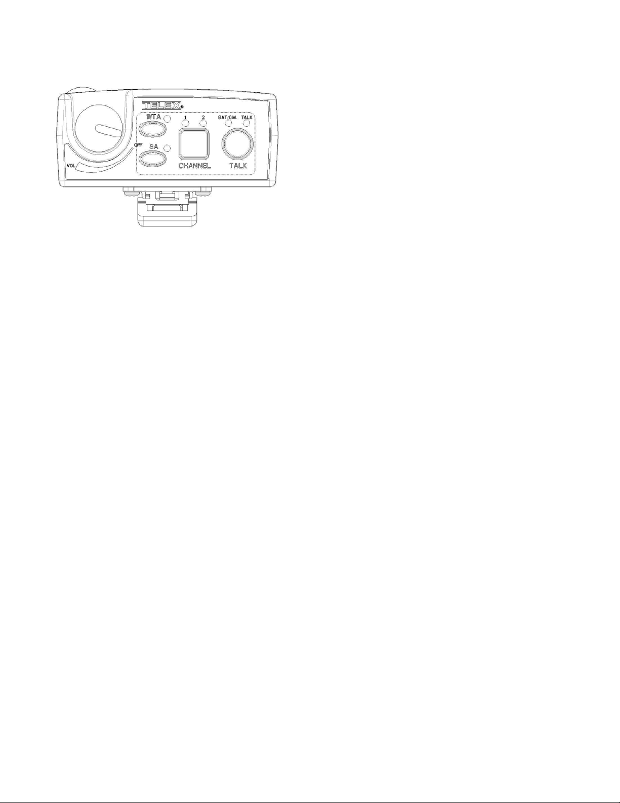
The on/off/volume control, talk button, talk light, low
battery indicator, microphone overmod. light, audio
channel 1 or 2 button and lights, wireless talk around
(WTA) and stage announce (SA) buttons are located
on the top panel.
Transmit and receive antennas are attached to the TR80N. Either or both unscrew for field replacement but
are not coaxial connectors.
The TR-80N beltpack can be powered by AA Alkaline
or a Nickel-Metal Hydride Battery pack.
Page 1 of 3
Page 2
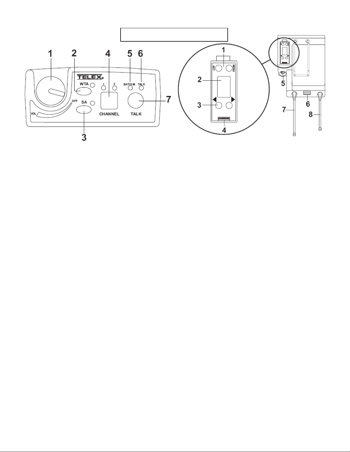
Controls and Connections
1. ON/OFF & Volume Control – Turns the beltpack power on and controls
headset volume.
2. WTA Button and Light – Wireless talk button. When pressed, the user’s
audio is disconnected from the wired intercom at the base station.
3. SA Button and Light – Wireless talk button. When pressed, the user’s
audio is routed to the stage annouce connector on the back of the base
station. The user also loses their sidetone as an indication that stage
announce is activated.
4. Audio Channel Select Button and Lights –Allows the user to select either
audio channel 1 or 2.
5. BAT/O.M. Light –
Battery - Light flashes on power up = Battery OK
Light on continuously = Battery Low
Light does not flash or come on = Battery Dead
Microphone Lvl: Light flashes on loudest speech = Gain OK
Light flashes on all speech = Gain too High
Light never flashes on loudest speech = Gain too Low
6. Talk Light – LED is on when the talk button, SA or WTA is active.
7. Talk Button – Press to enable the audio path from the headset.
Software Selectable modes: Push-to-Talk
Push-to-Latch
1. [MENU] and [SET] buttons – Used to select menus and set options
on the LCD.
2. LCD display.
3. [UP] and [DOWN] buttons - Used to select menus and set options on
the LCD.
4. Programming Connector – Used to update flash in unit.
5. Headset Connector – XLR Plug for Telex units, XLR Receptacle for
RTS units.
6. Battery Latch – Press down to enable the battery pack to be released.
While the latch is held down, slide the battery pack about 1/8 inch
back, toward the latch, until it stops, then lift out.
7. Receive Antenna – The antennas are screw type, ¼ wave, replaceable
antennas. The color dot on the screw end of the antenna must match
color dot on antenna receptacle.
8. Transmit Antenna – The antennas are screw type, ¼ wave,
replaceable antennas. The color dot on the screw end of the antenna
must match color dot on antenna receptacle.
Page 2 of 3
Page 3

Specifications:
General:
Input Power…………..9.0 VDC Alkaline or NiMH.
Antennas…………………………………Attached
TX / RX………………..One TX, one RX
Frequency agile, 25 KHz steps,
within 18MHz wide allotments.
Frequency Range
TX…………….614 – 722 MHz
RX…………….482 – 608 MHz
(within 18MHz wide allotments)
FCC ID: B5DM530
Transmitter:
RF Power Output……………Selectable or Auto
between levels: 5mW,
50mW, 100mW typical
(terminated)
Final Voltage (100mW)…………..4.75 VDC
Final Current (100mW)…………..25mA
Modulation type……………….….FM
Deviation………………………….5 kHz
Audio Frequency Response………100 Hz to 7 kHz
Microphone Sensitivity ……..……10 mV
Receiver:
Sensitivity…………<0.6uV for 12 dB SINAD Typical
Audio Frequency Response….100 Hz to 7 KHz
Audio Output (headset)…….40 mW, 600 Ohms
(1% Distortion)
Approval Information:
FCC
The Telex TR-80N Transmitter/Receiver is type
accepted under United States Federal Communications
Commission Part 74.
This device complies with Part 15 of the FCC Rules.
Operation is subject to the condition that this device
does not cause harmful interference.
Licensing of Telex equipment is the users
responsibility and licensability depends upon the
user’s classification, user’s application and frequency
selected. Telex strongly urges the user to contact the
appropriate telecommunications authority for any
desired clarification.
CAUTION: Any changes or modifications made to
the above equipment could void the user’s authority
to operate the equipment. NOTE: The beltpack is
intended to be worn on the belt of the user with both
antenna’s vertical for best operating range and
performance. Placing the beltpack in other locations
on the body may reduce preformance and void the
user’s authority by the FCC to operate the equipment.
Industry Canada
The Telex TR-80N Transmitter/Receiver is Certified
to Industry Canada RSS-123 rules.
Licensing of Telex equipment is the users
responsibility and licensability depends upon the
user’s classification, user’s application and frequency
selected. Telex strongly urges the user to contact the
appropriate telecommunications authority for any
desired clarification.
CAUTION: Any changes or modifications made to
the above equipment could void the user’s authority
to operate the equipment.
Page 3 of 3
 Loading...