

Page 1

Telex Model BTR-1 Base Station
Owners / Users Manual
(Preliminary Information)
General Description:
The Telex model BTR-1 base station transceiver is a
component of the BTR-1 wireless intercom system.
The BTR-1 is intended for use as a rack mountable
wireless full duplex intercom radio for use in a
professional installation such as television or cinema
production.
Each BTR-1 base station can be used with one TR-1.
The BTR-1 transmits within the 482 to 607.9 MHz
range (TV Channels 16-36). It receives in the 614.1
to 746 MHz range (TV Channels 38-59). The BTR-1
transmitter operates on a single frequency within an 18
MHz wide section of the transmit frequency range.
The receiver also operates on a single frequency within
an 18 MHz wide section of the receiver frequency
range.
Typical transmitter conducted output power is 50 mW.
Operating frequencies can be selected from pre-set
groups or the user can select special operating
frequencies within the 18 MHz wide allotments.
The transmit and receive antennas may be screwed
onto the BTR-1 via the TNC Female connectors on the
back of the unit. Always make sure the color dot on
the back of the base near the antenna jack matches the
color of the antenna.
Page 1 of 3
Page 2
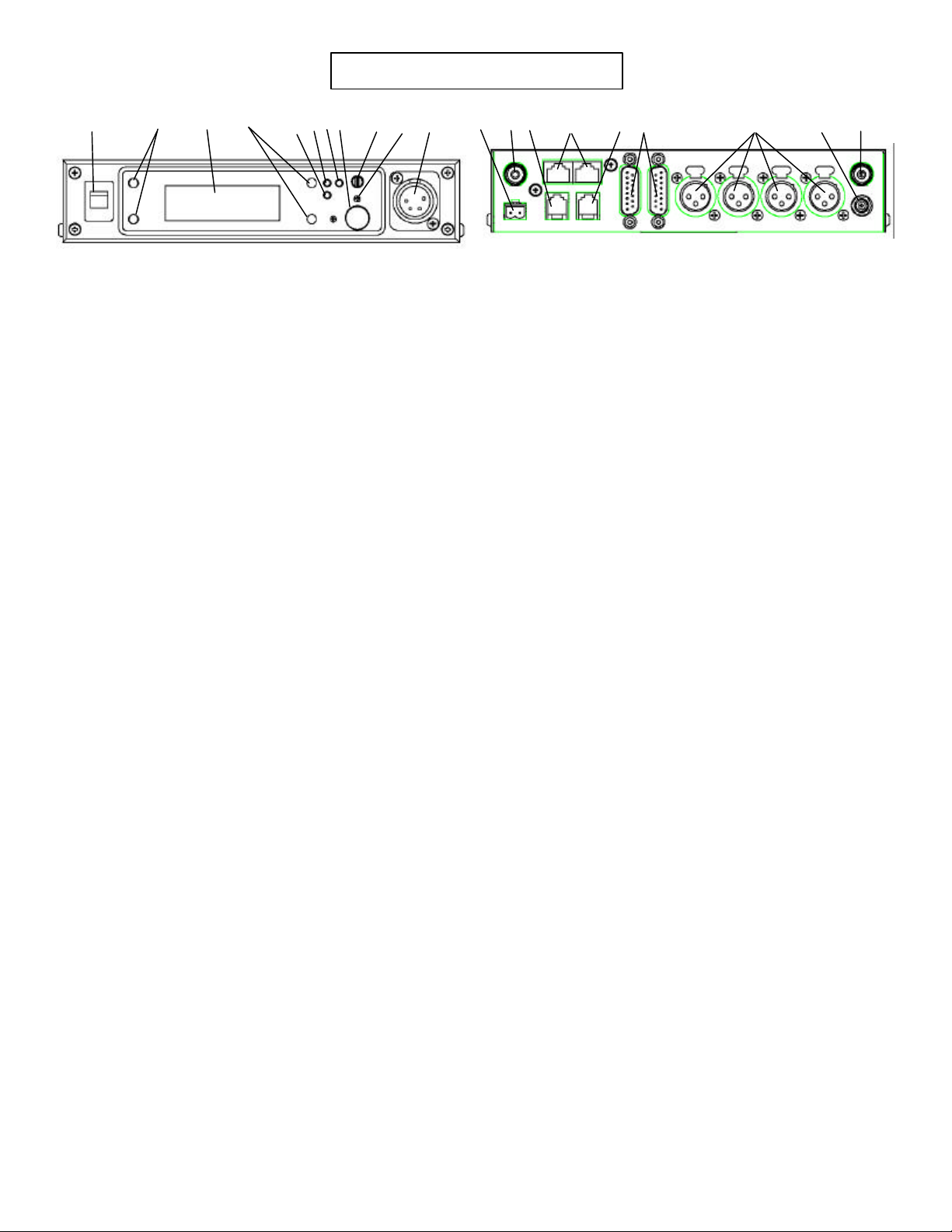
Controls and Connections
2 3 4 7 8 6 5 9
14
1
11 13
10
1. On/Off Switch – Turns the base station on/off.
2. [MENU] and [SET] buttons – Used to select menus and set options on the
3. Backlit LCD.
4. [UP] and [DOWN] buttons - Used to select menus and set options on the
5. Peak Aux Level Light – Will flash red when the auxiliary input level into
6. Peak Intercom Level Light – Will flash red when the intercom input levels
7. Talk Light – Green when the talk button is active. Will turn red when the
8. Talk Button – Press to enable the audio path from the headset.
9. Headphone Volume – Used to adjust the volume level out to a headphone.
10. Microphone Gain – Adjusts the audio gain from the local headset
11. Local Headset Jack
Pin 1 = Ground
Pin 2 = Microphone (Hot)
Pin 3 = Audio Out +
Pin 4 = Audio Out -
LCD.
LCD.
the base station is too high.
into the base station are too high.
microphone level into local headset is too high.
microphone.
12
12. Relay Contacts – Normally Open. When activated they close.
13. Receive Antenna Connector – TNC Female connector. The color dot
14. Auxiliary Connector – RJ-11 connector used to connect auxiliary
15. CAN bus – RJ-45 connectors used to connect a base station to a CAN
16. Matrix Connector – RJ-11 connector used to connect balance 4-W
17. Intercom Loop Thru – Two DB15 connectors used to loop intercom
18. Intercom Jack – XLR intercom jack to allow audio into the base via
19. Power Connector – Input power jack which requires 12 to 15 Volts
20. Transmit Antenna Connector – TNC Female connector. The color
15
16 17
near the connector must match the color of the antenna.
audio into and out of a base station.
type of bus.
audio into and out of the base station.
audio thru a base station.
XLR connectors instead of DB15 connectors.
AC or DC at 1000 mA.
dot near the connector must match the color of the antenna.
18
19 20
Page 2 of 3
Page 3

Specifications:
General:
Input Power…………..12 – 15 VDC/VAC @ 1000 mA
Antennas………………1/2 wave, TNC male connectors
TX / RX……………….One transmitter, one receiver,
Frequency agile, 25 KHz steps,
within 18MHz wide allotments.
Frequency Range
RX…………….614.1 – 746 MHz
TX…………….482 – 607.9 MHz
(within 18MHz wide allotments)
TX / RX Data Rate………………..….150 kbps
Aux In………………………………..2 Vrms typical
Aux Out………………………………2 Vrms typical
4-wire In……………………………..2 Vrms typical
4-wire Out……………………………2 Vrms typical
Transmitter:
RF Power Output…………………50 mW typical
(terminated)
Modulation type………………….GMSK
Audio Frequency Response………100 Hz to 7 kHz
Microphone Sensitivity ……..……10 mV
Receiver:
Sensitivity…………<0.8uV for 12 dB SINAD Typical
Audio Frequency Response….100 Hz to 7 KHz
Audio Output (headset)…….40 mW, 600 Ohms
(1% Distortion)
Page 3 of 3
 Loading...