

Page 1
UR-220S / 220D Series
Professional UHF Wireless Microphones
Installation and Operation
Page 2

Conte nts
Intro duc tio n… …………… … … … … … … … … … … … … …………… … … … … … … …P3
Recei ver Ins tal lat ion and Con nec tions… … … … … … ………… … … … … … … … … ……… … P4
·Installat ion… … … … … … … … … … … … ………… … … … … … … … … … … … … … ………P4
·Conn ect ion s……… … … ……… … … … …… … … … …… … … … ……… … … ……… … … …P4
Recei ver Con tro ls and Functi ons… … … … … … … … … … … … … … … … … … … … … … … …P 5
UR-22 0S Fr ont pan el… …… … … …… … … …… … ……… … ……… … ……… … …… … … ……P5
UR-22 0S Re ar p ane l……… … … …… … … ……… … … …… … … ……… … … ……… … … ……P6
UR-22 0D Fr ont panel… …… … ……… … ……… … …… … ……… … ……… … …… … … …… …P7
UR-22 0D Re ar p ane l…… … … ……… … … …… … … ……… … ……… … … …… … … ……… …P9
Tra nsm itt er C ont rol s an d Function s…… … … … ……… … … … ……… … … ……… … … … …P10
·H and hel d Mi cro pho ne… … … ……… … … … … ……… … … … … ……… … … … … ………P10
· Bodyp ack Tra nsm itt er… … … … … … … … … … … … … … … … … … … … … … … … … … P11
Tra nsm itt er Battery In sta lla tio n… … … … … … … … … … … … … … … … … … … … … … … …P1 2
Syste m Setup… … … … ……… … … … … … ……… … … … … ……… … … … … … ……… … …P 14
·Rece ive r Setup… … … ……… … … … ……… … … ……… … … … ……… … … ……… … …P14
·Tr ans mit ter Set up… … …… … … … …… … … … …… … … ……… … … ……… … … ………P15
Speci fic ati ons… … …… ……… …… … …… ……… …… … …… ……… …… … …… ……… ……P 17
… … …
Thank y ou fo r cho osi ng a RE LACART p rof ess ion al wireless mic rop hon e sys tem . You have joined
thous and s of ot her s ati sfied custome rs. O ur ye ars o f pro fessional exp eri enc e of de sig n and
manuf act uri ng to e nsu re our products ' qua lit y, pe rfo rmance and reli abi lit y.
Page 3
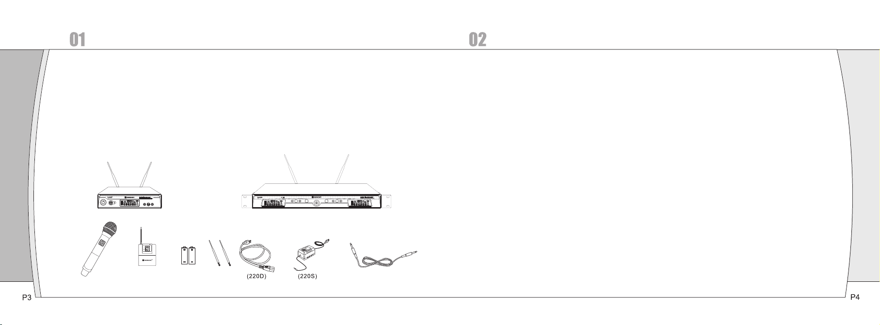
Introduction
Receiver Installation and Connections
①EIA-s tan dar d met al 1/ 2 - rack receiver c has sis , ant enn a diversity.
②The Han dhe ld Tra nsm itt er offer s dur able, ergonom ic me tal b odi es, soft-touch con tro ls.
③Brigh t and e asy -to -re ad LCD display sh ows R F/A F, di ver sity strength s; tr ans mit ter b attery level;
meanw hil e, ca n set u p sel ective channe l, fr equ enc y, mut e and o the r working status.
④Press t he "A FS" (A uto F req uen cy Selection) b utt on 3 S and t he re cei ver will auto-scan and l ock
on to an op en, i nte rfe ren ce-fr ee frequency
⑤Press [ IR] b utt on to u plo ad automatica lly t he re cei ver f requency to the t ran smi tte r.
⑥PLL (Ph ase L ock L oop f req uency control ) des ign e nsu res t ransmission r eli abi lit y, " Noi seLock"
squel ch effectiv ely b loc ks st ray R F.
⑦Each ch ann el 32 s ele cta ble frequenci es, d ual - cha nne l total 768 selec tab le fr equ enc ies.
⑧Batte ry li fe is u p to 15 h our s.
⑨Desig ned f or us e on pr ofe ssional tours , con cer t hal ls an d houses of worsh ip. S tab le fu nct ions,
relia ble a nd fl exi ble p erformance, e asy t o ins tal l.
Insta llati on:
①For bet ter o per ati on th e receiver shou ld be a t lea st 3f t. 1m a bove the ground a nd at l eas t 3ft .
away fr om a wa ll or m eta l sur face to minimiz e ref lec tio ns.
②Attac hed a p air o f UHF a nte nnas to the anten na in put j ack s, th e antenna are nor mal ly po sit ion ed in the
shape o f a “V” (bo th 45°f rom v ert ical) for best re cep tio n.
③Keep an ten nas a way f rom n oise sources su ch as c omp ute r, dig ital equipmen t, mo tor s, au tom obiles
and neo n lig hts , as we ll as a way from large me tal o bje cts .
④Keep op en sp ace b etw een t he receiver and t ran smi tte r for b etter recepti on.
⑤The tra nsm itt er sh oul d be at least 3ft. fr om th e rec eiv er.
( )
Conne ction s:
①The swi tch ing p owe r sup ply is designed t o ope rat e pro per ly from any AC power s our ce 10 0-2 40V,
50/60 Hz wi tho ut us er ad justment. Sim ply c onn ect t he re ceiver to a stand ard AC p owe r out let , using only
an IEC- typ e inp ut co rds et approved for t he co unt ry us e. Po wer to the unit is co ntr oll ed by t he fr ont panel
power s wit ch.
②There a re tw o aud io ou tpu ts on the rear pane l: an X LR mi cro pho ne output and a 1/4” ( 6.3 mm) p hon e
jack in str ume nt ou tpu t. The two isolat ed au dio o utp uts p ermit simulta neo us fe eds t o two d iff ere nt
input s. Us e the a ppr opr iate shielded a udi o cab le fo r con nections betw een t he re cei ver and the
input ( s) of t he mi xer o r oth er equipment.
3, Rece ive r Con tro ls an d Functions
SET
SET
SYNC
SYNC
Page 4

Receiver Controls and Functions
Figur e A: UR -220S R eceiv er Fron t Panel
①Power S wit ch:Pr ess p owe r switch in 3 secon ds an d the r ece ive r readouts will l igh t.
②Infra red D ata Tr ans fer B utton (SYNC): P res s thi s but ton t o transmit the ch ann el da ta fr om re ceiver to
trans mit ter.
③Infra red D ata Tr ans fer W indow (iR): Tran smi t channel data from th e rec eiv er to t he transmitte r,
so that t hey a re in t he sa me fr equency.
④LCD Win dow : Liq uid C rys tal Display ind ica tes c ont rol s etting and oper ati ona l rea din gs. See
“Syste m set up” on p age X f or de tails.
⑤UP / DO WN Buttons:
A, Pres s Up or D own a rro w but ton, in conjunc tio n wit h the S et bu tton, to step thr oug h men us, s ele ct
opera tin g fre que ncy a nd edit receive r fun cti on ch oic es.
B, Pres s Up or D own a rro w but ton 3 seconds and t he re cei ver w ill a uto-scan and lo ck on t o an
open, i nte rfe ren ce- free frequenc y.
②SET Button: Use in con jun cti on wi th th e Up / Down arrow but ton s to st ep th rou gh menus, choos e
opera tin g fre que ncy a nd select recei ver f unc tio n opt ions.
Figur e B: UR-2 20S Rec eiver R ear Pan el
①Anten na In put J ack : BNC t ype antenna con nec tor f or tu ner ”B”, a ttached the ant enn a dir ect ly.
②Volume B utt on: To adjus t the v olu me.
③Balan ced O utp ut Ja ck: X LR type connect or. A stand ard 2 c ond uct or shielded cab le ca n be us ed to c onn ect
the rec eiv er ou tpu t to a ba lanced microp hon e lev el in put o n a mixer or integr ate d amp lif ier.
④Unbal anc ed Mi xed O utp ut Jack: Unbala nce d Mix ed Ou tpu t Jack: 1/4” (6.3m m) ph one j ack . Can b e
conne cte d to an a ux- lev el input of a mixer , gui tar a mp or t ape r ecorder.
⑤Unbal anc ed Mi xed O utp ut Attenuator: Two-positio n swi tch a dju sts audio outpu t lev el, w ith a tte nuation
of 0dB, - 10d B.
⑥DC Powe r Out put J ack : 12V / 7 00mA.
⑦Anten na In put J ack : BNC t ype antenna con nec tor f or tu ner ”A”, a ttached the ant enn a dir ect ly.
Page 5

Figur e C: UR-2 20D Rec eiver F ront Pa nel
⑤A Channe l SET Button: U se in c onj unc tio n with the Up / Down ar row b utt ons t o ste p through menus ,
choos e ope rat ing f req uency and selec t rec eiv er fu nct ion options.
⑥A Channe l Inf rar ed Da ta Tra nsfer Button (S YNC ): Pr ess t his b utton to transm it A chann el da ta fr om
recei ver t o tra nsm itt er.
⑦B Chann el In fra red D ata Tr ansfer Button ( SYN C): P res s thi s button to trans mit B c han nel d ata f rom
recei ver t o tra nsm itt er.
⑧B Chann el UP / DOWN Butt ons :
A, Pres s Up or D own a rro w but ton, in conjunc tio n wit h the S et bu tton, to step thr oug h men us, s ele ct
opera tin g fre que ncy a nd edit receive r fun cti on ch oic es.
B, Pres s Up or D own a rro w but ton 3 seconds and t he re cei ver w ill a uto-scan and lo ck on t o an op en,
inter fer enc e-f ree f requency.
①Power S wit ch:Pr ess p owe r switch in 3 secon ds an d the r ece ive r readouts will l igh t.
②A Channe l LCD W ind ow: L iqu id Crystal Disp lay i ndi cat es co ntrol setting a nd op era tio nal readings. See
⑨B Chann el LC D Win dow : Liq uid Crystal Dis pla y ind ica tes c ontrol settin g and o per ati ona l readings.
See “Sy ste m set up” o n pag e X for details.
“Syste m set up” on p age X f or de tails.
③Infra red D ata Tr ans fer W indow (iR): For b oth A an d B cha nne l. Trans mit c han nel d ata f rom the
recei ver t o the t ran smi tter, so that the y are i n the s ame f req uency.
④A Channe l UP / DOWN Butto ns:
A, Pres s Up or D own a rro w but ton, in conjunc tio n wit h the S et bu tton, to step thr oug h men us, s ele ct
opera tin g fre que ncy a nd edit receive r fun cti on ch oic es.
B, Pres s Up or D own a rro w but ton 3 seconds and t he re cei ver w ill a uto-scan and lock o n to an o pen ,
inter fer enc e- fre e fre que ncy.
SET
SET
SYNC
SYNC
Page 6

Transmitter Controls and Functions
Figur e D: UR-2 20D Rec eiver R ear Pan el
Handh eld Mic ropho ne
1 2 3 4 5 6 7 8 9 10
①AC Powe r Inp ut: I EC ty pe co nnector for 100 -24 0V, 50/60Hz witho ut us er ad jus tme nt.
②Anten na In put J ack : BNC t ype antenna con nec tor f or tu ner ” B”, attached th e ant enn a dir ect ly.
③B Chann el Vol ume B utt on: To ad jus t the v olu me.
④A Channe l Volu me Bu tto n: To adj ust t he vo lume.
⑤B Chann el Ba lan ced O utp ut Jack: XLR type c onn ect or. A stan dar d 2 conductor shi eld ed ca ble c an be
used to c onn ect t he re cei ver output to a bal anc ed mi cro pho ne level input on a m ixe r or in teg rat ed
ampli fie r.
⑥A Channe l Bal anc ed Ou tpu t Jack: XLR type co nne cto r. A sta nda rd 2 co nductor shiel ded c abl e can b e
used to c onn ect t he re cei ver output to a bal anc ed mi cro pho ne level input on a m ixe r or in teg rat ed
ampli fie r.
⑦Unbal anc ed Mi xed O utp ut Jack: Unbala nce d Mix ed Ou tpu t Jack: 1/4” (6.3 mm) p hon e jac k for b oth A
and B cha nne l. Ca n be co nne cted to an aux-le vel i npu t of a mi xer, g uitar amp or tape r eco rde r.
①Unbal anc ed Mi xed O utp ut Attenuator: Two-positio n swi tch a dju sts audio outpu t lev el, w ith a tte nuation
of 0dB, - 10d B.
②DC Powe r Out put J ack : 12V / 7 00mA.
③Anten na In put J ack : BNC t ype antenna con nec tor f or tu ner ” A”, attached th e ant enn a dir ect ly.
①Micro pho ne He ad: T he mi cro pho ne he ad is separate to c han ge ot her m icrophone hea d if ne ede d.
②LCD Win dow : Liq uid c rys tal display ind ica tes o per ati onal frequenc y and b att ery c ond ition. The
trans mit ter 's “f uel g auge” battery i ndi cat or di spl ays a maximum of 4 ba r seg men ts. W hen i t leaves 1 bar
segme nt, t he ba tte rie s should be repla ced i mme dia tel y to ensure conti nue d ope rat ion .
③Infra red D ata R ece ivi ng Window (iR): U se to r ece ive t he ch annel data from t he re cei ver.
④Batte ry Co ver : Uns cre w it can reveal the b att ery c omp art ment.
⑤Batte ry Co mpa rtm ent : Insert 2 fresh 1. 5V AA bat ter ies . (Al kaline type is re com men ded , alw ays replace
both ba tte rie s.) O bse rve correct pol ari ty as m ark ed in side the batter y com par tme nt.
⑥Power B utt on.
P9 P10
Page 7

Body- pack Tra nsmit ter
Transmitter Battery Installatio n:
1
3 4
5
1
2
①Anten na
②Power B utt on
③Mute Bu tto n: Wh en th e tra nsmitter is mut ed, i t pro duc ts RF w ith no audio sign al mo dul ati on; w hen the
trans mit ter i s un- mut ed, it products b oth R F and a udi o.
④Audio I npu t Jac k: To con nec t 4-p in mi ni- XLR connector.
⑤LCD Win dow : Liq uid c rys tal display ind ica tes o per ati onal frequenc y, channe l and b att ery c ond ition. The
trans mit ter 's “f uel g auge” battery i ndi cat or di spl ays a maximum of 4 ba r seg men ts. W hen i t leaves 1 bar
segme nt, t he ba tte rie s should be repla ced i mme dia tel y to ensure conti nue d ope rat ion .
⑥Infra red D ata R ece ivi ng Window (iR): U se to r ece ive t he ch annel data from t he re cei ver.
⑦Batte ry Do or Sw itc h: Op en the battery do or by s lid ing t he sw itch.
⑧Batte ry Co mpa rtm ent : Insert 2 fresh 1. 5V AA bat ter ies . (Al kaline type is re com men ded , alw ays replace
both ba tte rie s.) O bse rve correct pol ari ty as m ark ed in side the batter y com par tme nt.
⑨AF / GT Aud io Input Switch: Con nec t an au dio i nput device (mi cro pho ne or g uit ar cable) to the au dio i npu t
jack on t he to p of th e bod y-p ack transmitt er. Ch oos e AF for m icr ophone input, t hen G T for guit ar ca ble t o
conne ct wi th gu ita r or ot her instrumen ts.
6
9
7
8
Page 8

System Setup
Recei ver S etu p
①Tur n dow n the AF l evel of the associat ed mi xer o r amp lifier, and make s ure t hat a ny UR t ran smitters
are tur ned o ff.
②Tur n on th e rec eiv er, the LCD displa ys th e pre set d ata.
③To change t he fr equ enc y by ma nual or “AFS” (Au to Fr equ enc y Sca n).
a, Touc h / button once to se lec t a new f req uen cy.
b, Pres s and h old / b utt on 3 se conds and the rec eiv er wi ll au to- scan and lock on to a n ope n,
inter fer enc e-f ree f requency.
④To enter th e men u mod e: Pr ess a nd hold the Set but ton 3 s eco nds t o ent er the edit mode, t ouc h /
butto n onc e to se lec t and s et SQELCH, DISP LAY or LO CK.
A, SQEL CH: S ele cti ng “S QELCH”, then to uch S ET Butto n to en ter e dit m ode , the small data fl ash es to
indic ate e dit , tou ch / bu tton to scroll throu gh th e ava ila ble choice for th e fun cti on. T he sq uel ch le vel
is adju sta ble i n ten 5 dB st eps, providin g a 50d B ran ge. P res s SET Butt on to c onfirm the desi red c hoi ce,
then LC D ret urn t o its p rev iously displa yed c ont ent s. (I f interferenc e is a pr obl em, f irs t consider tryi ng a
different freque ncy, either ma nua lly o r sca nning.)
B, DISP LAY: Selectin g “DI SPL AY”, t hen t ouc h SET B utt on to e nte r edit mode, touc h arr ow bu tto n,
“FREQ UEN CY” f las hes , if stopping on “F REQ UEN CY” , the L CD will display t he op era tio nal f requency;
touch a rro w but ton , “CH ANNLE” flashe s, if s top pin g on “C HANNEL”, the LC D wil l dis pla y the
opera tio nal c han nel . Press SET But ton to confirm th e des ire d cho ice , then LCD return t o its p rev iou sly
displ aye d con ten ts.
C, LOCK : Sel ect ing “ LOC K”, then touch SE T Button to ent er ed it mo de, t ouc h arrow button, i t
displ ays “ ON” , if st opp ing on “ON”, the sy ste m ent ers l ock m ode, the user can n ot us e any b utt on fo r any
contr ol; t ouc h arr ow bu tton, it displa ys “O FF” , if st opp ing on “OFF”, the u ser c an do a ny co ntr ol by
any but ton . Pre ss SE T But ton t o con fir m the desired cho ice , the n LCD r etu rn to its previou sly d isp lay ed
conte nts .
Page 9

Transm itter S etup
①Press a nd ho ld po wer b utt on 3 seconds, the L CD wi ndo w com es on .
②Frequ enc y set up: To le t the t ran smi tte r IR receiving wi ndo w fac e to th e rec eiver IR data tra nsf er
windo w, the n pre ss “S YNC ” button, the tra nsm itt er wi ll re ceive the frequ enc y / cha nne l dad a from
the rec eiv er, si mul tan eously the LCD di spl ays t he sa me fr equency / chann el as t he re cei ver
(Figu re E) .
(Figu re E)
SET
SET
SYNC
SYNC
SET
SET
SYNC
SYNC
A, Turn on o ne tr ans mit ter, t o let the transmi tte r IR re cei vin g window face to th e rec eiv er IR d ata t ransfer
windo w, the n pre ss A Chan nel 's “SYNC” butto n, th e tra nsm itt er will receive t he fr equ enc y / cha nnel
dada fr om A Chann el, s imu lta neously the LCD disp lay s the s ame f requency / chan nel a s the r ece ive A
Chann el.
B, Turn on t he ot her t ran smi tter, to let the tra nsm itt er IR r ece iving window fa ce to t he re cei ver I R data
trans fer w ind ow, th en pr ess B Channel's “ SYN C” bu tto n, th e transmitter w ill r ece ive t he fr equency /
chann el da da fr om B Ch ann el, simultane ous ly th e LCD d isp lays the same fre que ncy / c han nel a s the
recei ve B Ch ann el.
ii
Page 10

Specifications
07
UR-22 0S / UR-2 20D Rec eiver
Main Fr ame S ize: E IA STAN DAR D 1/2 U ( UR- 220 S) / EIA STAND ARD 1 U (UR-220D)
Chann els: S ing le Ch ann el (UR-220S) / Du al Ch ann el (U R-2 20D)
Frequ enc y Sta bil ity: ± 0.005%, Phase L ock L oop f req uen cy control
Carri er Fr equ enc y Ran ge: UHF 618-936 MH z
Digit al Eq ual ize r: Pr eset Micropho ne Ca psu le Mo del ing
Modul ati on Mo de: FM
Opera tin g Ran ge: 60 M typ ical ( in open spac e)
Oscil lat ion: P LL synthesized
Sensi tiv ity: 5 dBμ V, S/N>60dB at 2 5 dev iat ion
Band Wi dth: 1 6MH z (UR -22 0S); 32MHz (UR- 220 D)
Max.D evi ati on Ra nge: ± 45KHz
S/N: >10 5dB
T.H.D.: <0 .4% @1K Hz
Frequ enc y res pon se: 80 Hz~18KHz±3d B
Power S upp ly: DC 1 2V / 1A (U R-2 20S) / 100-240V AC 50/ 60 Hz , 10W (UR -220D)
Wei ght: 1.9KG (UR-2 20S ); 4K G (UR -22 0D)
Dimen sio n: 210(W)X 4 3(H ) X 206 (D) – UR-220S / 421 (W) X 4 3(H ) X 206 (D) – U R-220D
Outpu t Con nec tor: X LR ba lanced & 6.3 φphon e jac k unb ala nce d
UH-20 0 Handh eld Mic ropho ne
Carri er Fr equ enc y Ran ge UHF 618 -93 6 MHZ
Oscil lat ion: P LL synthesized
Harmo nic r adi ati on: <- 65dBm
Bandw idt h: 32 MHz
Max.D evi ati on Ra nge: ± 45KHz
Micro pho ne El eme nt: Ca rdioid Dynami c / Car dio id Co nde nser
RF Powe r Out put: 8 mW
Batte ry: AA X 2
Curre nt Co nsu mpt ion: 9 0mA, typical
Batte ry Cu rre nt / Li fe: App roximately 15 h our s
Dimen sio n: 52(Φ) X 2 52 (L )
Wei ght: 208g ( w/o batt ery )
:
UT-200 B ody-p ack Tran smitt er
Carri er Fr equ enc y Ran ge UHF 618 -93 6 MHZ
Oscil lat ion: P LL synthesized
Harmo nic r adi ati on: <- 65 dBm
Bandw idt h: 32 MHz
Max.D evi ati on Ra nge: ± 45KHz
Input C onn ect or: 4- pin m ini-XLR conne cto r
RF Powe r Out put: 9 0mW
Batte ry: AA X 2
Curre nt Co nsu mpt ion: 9 0mA, typical
Batte ry Cu rre nt / Li fe: App roximately 15 h our s
Dimen sio n: 84( H) X 66 (W) X 2 3(D)
Wei ght: 165g ( w/o batt ery )
:
P17 P18
Page 11

Page 12

Page 13

USA acceptable band ( FCC compli ance ): 6 18.50 0 MHz – 633 .500 MH z
Canad a accep table b and ( IC co mplia nce ): 67 8.500 M Hz – 693. 500 MHz
Europ e accep table b and ( CE co mplia nce): 8 50.00 0 MHz – 865 .000 MH z
FCC NOT E:
This de vice co mplie s with Pa rt 15 of th e FCC Rul es. Ope ratio n is subj ect to th e follo wing tw o
condi tions :(1)t his dev ice may n ot caus e harmf ul inte rfere nce, an d (2) thi s devic e must ac cept
any int erfer ence re ceive d, incl uding i nterf erenc e that ma y cause u ndesi red ope ratio n.
The man ufact urer is n ot resp onsib le for an y radio o r TV in terfe rence c aused b y unaut horiz ed
modif icati ons to th is equi pment . Such mo dific ation s could v oid the u ser's a uthor ity to op erate t he
equip ment.
IC NOTE
Opera tion is s ubjec t to the fo llowi ng two co nditi ons:
(1)this devi ce may no t cause h armfu l inter feren ce, and ( 2) this d evice m ust acc ept any
inter feren ce, inc ludin g inter feren ce that m ay caus e undes ired op erati on of the d evice .
 Loading...