

Page 1
Installation Instructions
(716) 223-4060 • (888) 289-0096 • Fax: (716) 223-9180
P/N: 43744B 09/00
DS720i Long Range Dual PIR/Microwave
Intrusion Detector
1.0 Description
The DS720i is a long range dual passive infrared (PIR)/microwave
(mW) intrusion detector that utilizes state-of-the-art signal
processing to maximize catch performance and reduce false
alarms.
2.0 Specifications
• Description: DS720i Long Range Dual PIR/Microwave Intrusion
Detector.
• Input Power: 9 to 15 VDC, 32 mA DC nominal @ 12.0 VDC (up
to 60 mA DC during walk testing, stored alarms, or trouble
conditions).
• Standby Power: There is no internal standby battery. Connect to
DC power sources capable of supplying standby power if primary
power fails. 32 mA-H required for each hour of standby time
needed. Four hours (128 mA-H) minimum are required for
Underwriters Laboratories' Certificated installations.
• Alarm Relay: Silent operating Form "C" reed relay. Contacts
rated 3 watts, 125 mA, 28 VDC maximum for DC resistive loads;
and protected by a 4.7 ohm, 1/2 Watt resistor in the common "C"
leg of the relay. Do not use with capacitive or inductive loads.
Alarm relay contacts on terminals 3,4 and 5.
• Tamper: Normally Closed (with cover in place) tamper switch.
Contacts rated at 28 VDC, 125 mA maximum. Tamper contacts
on terminals 6 and 7.
• Trouble: Normally Closed dry contact output on terminals 8 and
9. The contacts are rated at 28 VDC, 125 mA maximum. Open
during trouble condition.
• Operating Temperature: -20° to +120°F (-29° to +49°C). For
U.L. Listed Requirements, the temperature range is +32° to
+120°F (0° to +49°C).
• Microwave Frequencies:
• DS720i: 10.525 GHz
• DS720i-A: 9.9 GHz
• DS720i-B: 10.687 GHz
• Coverage:
Standard Broad: 90 ft. by 70 ft. (27 m by 21 m) (OA90)
Optional Long Range: 120 ft. by 25 ft. (37 m by 8 m) (OA120)
Standard Long Range: 300 ft. by 15 ft. (91 m by 4.6 m) (OA300)
• Options: TC6000 Test Cord and OA120 Optical Module.
• U.S. Patent Numbers: # 4,660,024, # 4,764,755, #5,077,548,
#5,083,106, # 5,208,567, # 5,262,783, and # 5,450,062.
Other patents pending.
• Dimensions: 8.25 in. L x 5 in. W x 5.19 in. H (21 cm L x 13 cm W
x 13.2 cm H)
3.0 Installation Hints
Never install the detector in an environment that causes a constant
alarm in one technology; it should never be left to operate with the
green, yellow or red LED ON.
Point the unit AWAY from outside traffic (e.g. roads, alleys, and
parking lots). Remember: Microwave energy will pass through
glass and most common nonmetallic construction walls.
Point the unit AWAY from glass exposed to the outdoors and objects
that may change temperature rapidly.
Remember: The PIR detector will react to objects rapidly changing
temperature within its field-of-view.
Avoid installations where rotating machines (e.g. ceiling fans) are
normally in operation within the coverage pattern.
If using the anti-mask feature, avoid locations where people or
objects may be moving within 3 ft. (1 m) of the detector.
4.0 Mounting
Select a location that is most likely to intercept an intruder moving
across the coverage pattern (review coverage patterns on page 6).
The recommended mounting height for the 300 ft. x 15 ft. (91 m x
4.6 m) coverage is 10 ft. (3 m). The recommended mounting height
for the 90 ft. x 70 ft. (27 m x 21 m) and 120 ft. x 25 ft. (36.6 m x 8 m)
coverages is 7.5 ft. (2.3 m). The surface should be solid and
vibration-free.
Remove the cover by inserting a flathead screwdriver or other flat
object into the slot at the bottom of the cover, and twist until the
cover snaps free of the front tabs on the base. Lift the cover up and
away to clear the rear base tabs. Do not bend or remove the
microwave antenna located on the front of the permanent reflecting
mirror.
Remove the circuit board from the base by pressing the two circuit
board retainer tabs outward while lifting the circuit board away from
the base.
Select and break away the appropriate thin wall wire entrance and
mounting hole coverings in the base.
Using the base as a template, mark the location of the mounting
holes on the mounting surface, and pre-start the mounting screws.
Route wiring as necessary to the rear of the base and through the
wire entrance, then firmly mount the base to the mounting surface.
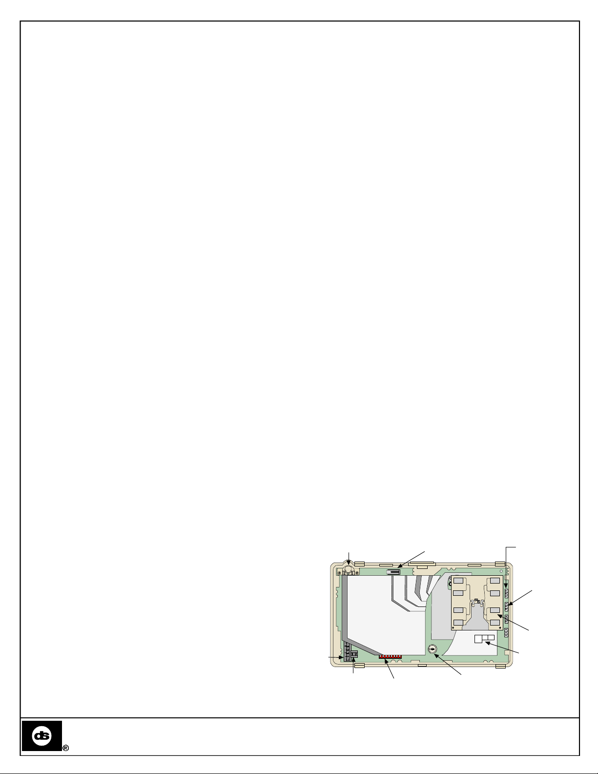
Terminal
Strip
Anti-Mask
Transmitter
1 2 3 4 5 6 7 8
Tamper Switch
MIN
MAX
PIR Noise
Voltage
Pins
Microwave
PIR
NV
Noise Voltage
MW
NV
AM
Microwave
MW
DO NOT TOUCH!
Light Pipe
Pins
Antenna
Detection Systems, Inc., 130 Perinton Parkway,
Fairport, New York, USA 14450-9199
Extra
Terminals
Set-up
Switch Bank
Microwave Range
Adjustm ent
Figure 1: Inside View of DS720i
Copyright © 2000 Detection Systems, Inc.
DS720i Installation Guide
Page 2
DS720i Installation Guide
© 2000 Detection Systems, Inc. All rights reserved.
Page 2
Retainer Tabs
Bracket Wire Entrance
Rear Wire Entrance
Corner Mount Holes (4)
Surface Wire
Entrance
Base
Cover Tabs
Surface Mount
Holes (4)
Figure 2: DS720i Base
Be sure all wiring is unpowered before routing.
The tamper switch's jumper pins determine whether the wall tamper
and bracket tamper features are enabled or disabled. See Figure 5
to set the jumper pins.
Enabled
Disabled
Jumper Pins for
Wall Tamper
Enabled
Disabled
Jumper Pins for
Bracket Tamper
Figure 5: Wall/Bracket Tamper Switch Jumper Pins
Figure 6 shows how to wire the tamper switch's terminals to the
control panel and the DS720i.
B334 Tamper Switch
Return the circuit board to the base by first inserting the bottom of
the circuit board into the cutouts at the bottom of the base, then
snapping the top into place.
3.1 Tamper Switch Installation
The tamper switch is designed to prevent any unauthorized opening
or manipulating of the B334 Mounting Bracket once it has been
mounted. The tamper switch mounts to the inside of the bracket
using the supplied circuit board mount.
Jumper Pins for
Bracket Tamper
Jumper Pins for
Wall Tamper
Wall Tamper
Figure 3: Optional Tamper Switch
Refer to Figure 4 when installing the tamper switch into the B334
Mounting Bracket.
Tamper
Terminal
Block
Bracket Tamper
To Panel Loop
6
7
DS720i
Figure 6: Wiring the Tamper Switch
3.2 B334 Bracket Mounting
Mount the B334 to a standard single gang switch or outlet box
using the supplied screws. If the unit is to be surface mounted, use
the wall screw/anchor assemblies or appropriate alternatives.
Slide the mirror from the black mirror mounting assembly when
feeding the power wiring through the detector base to the terminal
strip if required.
Refer to Figure 7 when mounting the DS720i to the B334 Mounting
Bracket.
Front View of B334
Wire Entrance
Stud Hole For
Ceiling Mounted
Bracket
Stud Hole
(Hidden) For Wall
Mounted Bracket
Mounting Holes (4)
Top View of
B334 Mounting Bracket
Install
Tamper Switch
Here
Fit spring through hole
in back of mounting bracket
Peel double-sided tape
Figure 4: Installing the Tamper Switch
Threaded
B334 Cover
Stud
Screwdriver Notch
Insert
B334 Body
Plug
Hex Nut
Detector Base
Figure 7: Mounting the B334 Bracket
Wiring
Route
Locking
Washer
Curved
Washer
Page 3
DS720i Installation Guide
© 2000 Detection Systems, Inc. All rights reserved.
Page 3
3.3 Mirror Replacement
Flashing Red 4 Microwave or PIR failure -- replace unit
The DS720i comes with two mirrors: OA300 (pre-installed), and
OA90 (optional). The mirrors slide on and off the mirror stand. To
replace the mirror, use the following steps:
1) Hold the base with one hand if the unit has not been mounted.
2) Use the other hand to pull the mirror off the mirror stand in an
upward-diagonal direction.
3) Align the runners on the inside of the mirror with the grooves on
the mirror stand.
4) Slide the mirror onto the mirror stand in a downward-diagonal
direction.
See Figure 5 for details.
Pull mirror off in an
upward-diagonal
direction.
Mirror
Mirror S tand
Slide mirror on in a
downward-diagonal
direction.
1 2 3 4 5 6 7 8
Mounting
Groove
4.0 Wiring
Only apply power after all connections have been made
and inspected.
Wire the terminal strip as shown in Figure 6.
Spare
12
Spare
11
Alarm
1 2 3 4 5 6 7 8 9 10
-
+
9-15 VDC
Input
C
NC
Alarm Relay Tamper
NO
T T
Figure 6: Wiring the DS720i Terminals
Terminals 1(–) & 2(+): Power limits are 9 to 15 VDC. Use no smaller
than #22 AWG (0.8 mm) wire pair between the unit and the power
source.
Terminals 3, 4, & 5: Alarm relay contacts rated 3 Watts, 125 mA, 28
VDC maximum for DC resistive loads and protected by a 4.7 ohm, 1/2
Watt resistor in the common "C" leg of the relay. Use terminals 3 & 4
for Normally Closed circuits. Do not use with capacitive or inductive
loads.
Terminals 6 & 7: Tamper contacts rated at 28 VDC, 125 mA.
Terminal 8 & 9: Terminals are normally closed when the detector is
not in trouble, and open when the detector is in trouble.
Terminal 10: Memory. Refer to Section 6.0 Feature Selection.
Terminals 11 & 12: Spare terminals.
Seal any openings with the foam plugs provided to
prevent drafts and insect entry. Use the (2) screws
provided to secure the detector cover to the base.
Trouble
TR
TR
Trouble
M
Memory
Input
Mirror
Mirror Stand
1 2 3 4 5 6 7 8
Figure 5: Replacing the DS720i Mirror
Align mirror with
mirror groove
5.0 LED Operation
The DS720i uses three colors to indicate the various alarm and/or
supervision trouble conditions that can exist. Refer to Table 1 for the
colors and their respective conditions.
Table 1: LED Functions
LED Function
Steady Red Unit alarm or stored alarm
Steady Yellow Intrusion detected by microwave section
Steady Green Intrusion detected by PIR section
Flashing Red 1 Warm-up calibration period after initial power-up
Flashing Red 2 Motion Monitor time-out
Flashing Green 3 IR Anti-Mask failure
Flashing Yellow 3 Microwave Anti-Mask failure
Flashing (color) 2-4: The LED flashes 2-4 times a cycle.
Page 4

DS720i Installation Guide
© 2000 Detection Systems, Inc. All rights reserved.
Page 4
The complete circuit operation of the PIR/ Microwave
30 Day
subsystems is checked every 5 hours. If the PIR or
Microwave subsystems fail two consecutive times, the
LED will flash red 4 times per cycle and the unit should
be replaced. The detector will default to PIR technology
protection if the Microwave subsystem fails. The PIR
processing will automatically be adjusted to reduce false
alarms. An intrusion alarm will reset most existing
supervision trouble conditions. There must be at least
10 seconds of no activity (no alarm) prior to the detector
alarm for a trouble clear to occur.
6.0 Feature Selection
The DS720i's features are selected using a bank of 8 DIP switches.
See Figure 1 for a location of the DIP switches.
See Figure 7 for default DIP switch positioning.
= ON (Low)
= OFF (High)
6.3 Motion Monitor
To set the Motion Monitor feature, refer to Table 2 for switches S3
and S4. The Motion Monitor Supervision feature verifies that each
technology has a clear view of the detection area. When selected,
a supervision timer is activated which gives the detector the ability
to indicate a supervision trouble condition if the time period has
elapsed since the last detector alarm. If the Memory feature is
used, the motion monitor time period will be increased by the
amount of time the detector is in the arm condition. If the detector
does not detect an alarm within the selected time period, the LED
will flash red 2 times to indicate a Motion Monitor Time-out
condition and the Trouble output will activate.
6.4 Anti-Mask/Spray Detection
The Anti-Mask feature detects attempts made to disable the
detector by covering it. The DS720i has Microwave Anti-Mask, IR
Anti-Mask and Spray Anti-Mask as standard features. When
activated, the detector will indicate an Anti-Mask supervision
trouble condition if a microwave reflective material (e.g. metal,
most plastics, etc.) is placed within one foot of the detector.
S1
The DS720i's features are assigned to the DIP switches as follows
(factory-set default settings in parentheses):
• S1: LED Operation (ON)
• S2: PIR Sensitivity: OFF - High; ON - Intermediate (ON)
• S3: Motion Monitor: see Table 2 (OFF)
• S4: Motion Monitor: see Table 2 (OFF)
• S5: mW Anti-Mask (OFF)
• S6: Anti-Mask Delay Timer (OFF)
• S7: PIR Anti-Mask (OFF)
• S8: PIR Spray Detect (OFF)
NOTE: To activate the spray detection feature, both switches S7
S2
Figure 7: Default DIP Switch Positioning
and S8 must be in the ON position.
Table 2: Motion Monitor DIP Switch Settings
S3
Motion Monitor S3 S4
Disabled OFF OFF
S4
1 Day ON OFF
4 Day OFF ON
S5
ON ON
S6 S7 S8
6.1 LED Operation
The ON position allows operation of the LED. If LED indication is not
desired after setup and walk tests are completed, place in the OFF
position. The OFF position does not prevent the LED from indicating
supervision trouble conditions.
6.2 PIR Sensitivity Selection
High Sensitivity (S2 OFF): For fast response to intruder signals.
This setting will improve your intruder catch performance.
Intermediate Sensitivity (S2 ON): Tolerates normal environments
on this setting. This setting will improve your false alarm immunity.
The anti-masking feature may interpret removal and/or
replacement of the cover as an attempt to mask the
detector and may signal a supervision trouble
condition. If this should occur, reset the detector by
removing and then reapplying its power. The trouble
condition will also be reset by the next detector alarm
after a 10 second period of no alarms from both
technologies.
This anti-mask feature also has a delay timer function that can be
turned ON or OFF with the selection of switch S6. When enabled
(switch S6 ON), this feature evaluates the anti-mask condition for
false alarms. For maximum anti-mask/spray detection performance,
this timer should be turned OFF.
The Spray Detection feature prevents accidental or intentional
blocking of the detector by detecting an object placed in close
proximity of the detector, or if the detector is sprayed with a foreign
substance. See Figure 8 for details.
Anti-Mask
Transmitter
Distance
Distance:
Approximately
1 ft. (0.3 m)
with Spray
Detect OFF
Approximately
3 ft. (0.9 m)
with Spray
Detect ON
Distance
Figure 8: Anti-Mask/Spray Detection Coverage
Page 5

DS720i Installation Guide
© 2000 Detection Systems, Inc. All rights reserved.
Page 5
6.5 Memory Operation
but less than 20 seconds)
Memory, Armed Mode and Walk Test require a supply voltage on
Terminal 10 to activate these features. This supply voltage must be
between 6 and 18 VDC. You may use a switch as shown in Figure
9:
NC C
+
-
NO T T TR TR
M
1 2 3 4 5 6 7 8 9 10
Figure 9: Alarm Memory Function
Or use an external power supply as shown in Figure 10:
-
+
NC C
NO T T TR TR
M
1 2 3 4 5 6 7 8 9 10
Control Panel
-
or
+
External DC
Supply
Figure 10: Alarm Memory Function with External Power
Supply
Control voltage: +6 to +18 volts = ON (Switch Closed); 0 volts =
OFF (Switch Open).
Day Mode: The Day Mode disables the alarm memory and allows
the LED (if activated) to operate normally.
Memory: When the DS720i is in the Night Mode the memory is
activated. This allows the detector to store an alarm for display at a
later time.
Armed Mode: The Night Mode enables the alarm memory and
disables the LED operation.
Remote Walk Test (LED Control): When the DS720i is in the
Walk Test mode, the LED will indicate the current alarm status
regardless of the setting of the LED Operation switch (Switch 1).
Table 2: Memory Operation Settings
Desired Action Control Voltage (Terminal M)
Turn ON Night Mode/
Reset Stored Alarm
Turn OFF Night Mode/
Display Stored Alarm
Turn ON Walk Test (if OFF)
Turn OFF Walk Test (if ON)
ON (for more than 20 seconds)
OFF
ON (for more than 5 seconds,
but less than 20 seconds)
ON (for more than 1 second,
7.0 Setup and Walk Tests
Place the LED switch in the ON position. If using the Memory Input
to enable the Remote Walk Test feature, it is not necessary to put
the LED switch in the ON position.
NOTE: Use a bubble level on the front of the unit to check for
proper positioning and alignment.
7.1 Establishing PIR Pattern Coverage
Turn the Microwave Range Adjust to minimum.
Replace the cover and snap it into place. This will close the tamper
switch.
During the warm-up period, the LED will flash red until
the unit has stabilized and has seen no movement for
2 seconds (approximately 1 to 2 minutes). When the
LED stops flashing, the detector is ready to be tested.
With no motion in the protection area, the LED should
be OFF. If the LED is ON, recheck the protection area
for disturbances affecting the microwave or PIR
technologies.
Walk test across the pattern at its farthest edge, then several times
closer to the detector. Start walking from outside of the intended
protection area, and observe the LED. The edge of the pattern is
determined by the first green, PIR activation of the LED (or the first
red activation if the yellow microwave LED activates first).
If the desired coverage cannot be achieved, try angling the
coverage pattern up or down to ensure the pattern is not aimed too
high or low. In a narrow aisleway, aiming the pattern slightly left or
right can also improve the detector's catch performance.
7.2 Establishing Microwave Coverage
Wait 1 minute after removing/replacing the cover so
the microwave portion of the detector can settle and to
wait at least 10 seconds between the following walk
testing procedures.
The LED should be OFF before walk testing.
Walk test across the pattern at the intended coverage's farthest
end. Start walking from outside the intended protection area and
observe the LED. The edge of the microwave pattern is determined
by the first activation of the yellow LED.
If an adequate range cannot be reached, increase the Microwave
Range Adjust slightly. Continue walk testing (waiting 1 minute after
removing/replacing the cover) and adjusting the range until the
farthest edge of desired coverage has been accurately placed.
Do not adjust the Microwave Range higher than
required. Doing so will enable the detector to catch
movement outside of the intended coverage pattern.
Walk test the unit from all directions to determine all the detection
pattern boundaries. Wait at least 10 seconds between walk tests.
7.3 Establishing Detector Coverage
All LEDs should be OFF before walk testing.
Walk test the unit from all directions to determine the detection
boundaries. A detector alarm is signaled by the first red activation
of the LED after an initial green or yellow LED activation.
Page 6

DS720i Installation Guide
© 2000 Detection Systems, Inc. All rights reserved.
Page 6
8.0 Meter Tests
An analog or digital volt meter is recommended. Use of the
TC6000 is recommended, but is not essential for meter use. Either
outside connector pin of the TC6000 may be used as common (-).
8.1 PIR Meter Readings
Connect the meter to the PIR Noise Voltage Pins. With no target
motion in the pattern, read the voltage. The base reference level for
PIR background is approximately 1.0 VDC. Installations in quiet
environments, therefore, should result in a steady meter reading
between 0.9 and 1.1 VDC.
Walk test across the farthest edge of the coverage pattern. Make
sure the detector's cover is on.
Voltage changes greater than +0.75 VDC from the reference level
during walk tests are desirable. If changes are less than 0.75 VDC,
the detector may fail to respond at this far a distance if the
temperature difference between the intruder and the background is
minimal. Try adjusting the unit up and down to maximize the voltage
change during walk tests.
Turn on all heating/cooling sources that will be in operation during
the times of protection. Stand away from the unit and outside the
protection pattern, then monitor background noise for at least 3
minutes.
Readings should not deviate more than 0.15 VDC from the
reference level. If they do, eliminate the cause or reposition the
pattern (observe readings while turning on and turning off these
sources as well as during the three minute interval).
8.2 Microwave Meter Readings
Connect the meter to the Microwave (mW) Noise Voltage Pins.
With no target motion in the pattern, read the voltage. The
background noise voltage should be steady, and should not exceed
1.0 VDC. If it does, the cause of the disturbance should be found
and eliminated.
10.0 Coverage Patterns
The protected coverage area is where the microwave and PIR
patterns overlap.
OA300 Long Range Coverage (pre-installed)
Top View
0 meters
7.5
0.0
7.5
0
10
0
C
DE
50 100 150 200
Side View
0 meters
E
C
D
0
50 100 150 200 250
B
feet
B
feet
0A90 Standard Broad Coverage (optional mirror - included)
Top View
0 meters
70
7.5
10
0
50
30
10
0
10
30
50
70
0
Side View
0 meters
K
0
I
K
J
I, J
F
G
H
E
30 50 70
feet
F - H
feet
91.4
2.3
A
2.3
300
250
76
3.1
A
0
300
24
18
A
9
B
3
C
40
°
3
D
9
18
90
A
G H
B C D E
B
A
OA300
K
F I J
C
OA90
24
3
0
90
705030
A - E
E
D
Microwaves penetrate nonmetallic surfaces.
Movement on the other side of walls and doors viewed
by the detector could cause unexpected background
noise readings.
9.0 Other Information
9.1 Maintenance
At least once a year, the range and coverage should be verified. To
ensure continual daily operation, the end user should be instructed
to walk through the far end of the coverage pattern. This ensures
an alarm output prior to arming the system.
9.2 Pattern Masking
Refer to the mirror module and pattern drawings in Section 10.0 for
masking.
Many adhesives will either destroy the mirror surface
or leave enough surface residue behind to reduce
coverage performance. Be sure to clean the mirror
surface with a mild window cleaning solution after
masking removal.
9.3 FCC Compliance Notice
This device complies with Part 15 of the FCC Rules and with RSS210 of Industry and Science Canada. Operation is subject to the
following two conditions: (1) this device may not cause harmful
interference, and (2) this device must accept any interference that
may cause undesirable operation.
OA120 Long Range Coverage (Optional)
Top View
0 meters
20
10
G
0
I
H
10
20
0 120
20 40 60 80 100
Side View
0 meters
10
7.5
I
0
G - H
0
20 40 60 80 100
D
F
D - F
E
feet
feet
A
B
C
A - C
36
6
3
0
3
6
36
3
0
120
D G H
A
E
B
OA 120
NOTE: Use a bubble level on the front of the unit to check for
proper positioning and alignment.
I
F
C
 Loading...