

Page 1

Robert Bosch (SEA) Pte Ltd
11 Bishan Street 21
573943 Singapore
Singapore
www.boschsecurity.com
© Robert Bosch (SEA) Pte Ltd, 2014
ALLPLEX track Personnel Transmitter
ATX-TRM-304T01 | ATX-TRM-433T01
en Quick Installation Guide
Page 2
ALLPLEX track Personnel Transmitter
Quick Installation Guide
1 FCC Information
Notice!
For the full FCC information, refer to the ALLPLEX track Personnel Transmitter Installation Manual which can be
downloaded from http://www.boschsecurity.com.
No.
Parts
1
Retaining screw
2
Lower Part
Notice!
Batteries must not be disposed of in household waste. Please take used batteries to the local collection points. See
www.boschsecurity.com/standards for further information.
No.
Parts
1
Dip switch for radio frequency (see Figure 3.2)
2
Battery compartment (3V)
3
Alarm button
4
Test button
5
Lanyard
Notice!
Remove the battery before setting the dip switches.
Use a white marker to indicate the configured RF on the back of the transmitter after setting the dip switches.
Changes to the dip switches should be performed by administrators only.
2014.03 | V1.0.0 | F.01U.268.386
Robert Bosch (SEA) Pte Ltd
Quick Installation Guide
ALLPLEX track Personnel Transmitter
No.
Parts
1
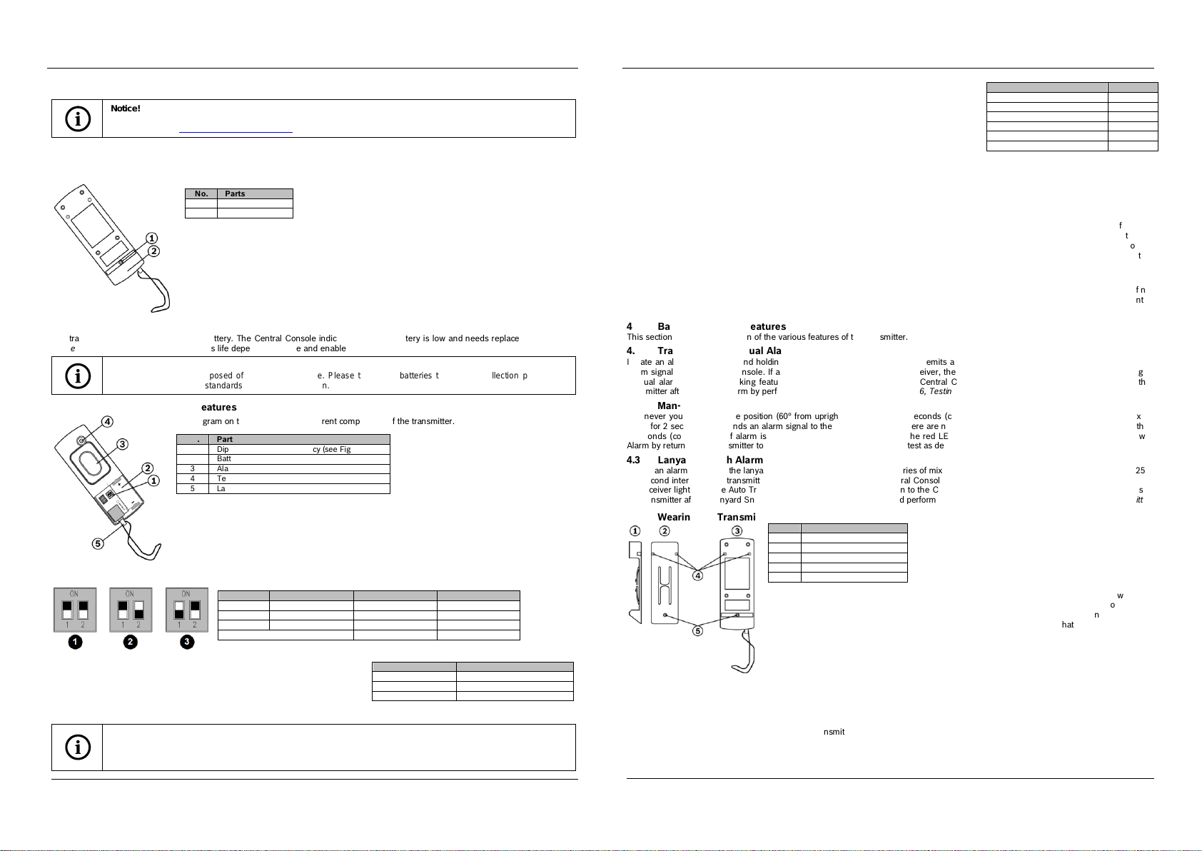
Side view of clip
2
Clip
3
Back of transmitter
4
Screw holes (mandatory)
5
Screw holes (optional)
Robert Bosch (SEA) Pte Ltd
2014.03 | V1.0.0 | F.01U.268.386
Diagram
Radio Frequency
Switch Number 1
Switch Number 2
1
304 MHz (default)
OFF
OFF
2
303.825 MHz
OFF
ON
3
433.42 MHz
ON
OFF
Used for Factory Reset
ON
ON
Radio Frequency
Number of Beeping Tones
303.825 MHz
1
304 MHz
2
433.42 MHz
3
Feature
Value
Transmitter Type
Security
Man-Down
Disabled
Supervision Tracking
Disabled
Lanyard
Disabled
Autotracking Interval
7 secs
Supervision Tracking Interval
90 secs
Figure 2.1: Back of Transmitter
Figure 3.1: Components of the transmitter
Figure 5.1: Belt Clip Attachment
Figure 3.2: Selecting Transmitter Radio Frequency
This device compli es with Part 15 FCC Rules. Operation is subject to the following two conditions: (1) thi s device may n ot cause harmful
interference, and (2) this device must accept any interference received including interference that may cause undesired operation.
2 Installation and Setup
This section provides information for the system planners and configurators.
2.1 Removing the Cover
2.2 Battery
The transmitter uses a CR2, 3V lithium battery. The Central Console indicates when the battery is low and needs r eplacement. Refer to
Figure 3.1 for battery polarity. The battery’s life depends on usage and enabled features.
3 Enabling and Disabling Features
3.1 Selecting Transmitter Radio Frequency
The radio frequency (RF) is set as 304 MHz by default. To change the RF to
303.825 MHz, set dip switch 1 to the OFF position and dip switch 2 to the ON
position. To change the RF to 433.42 MHz, set dip switch 1 to th e ON position
and dip switch 2 to the OFF position. Once the transmitter restarts after inserting
the battery, the transmitter will emit a number of beeping tones depending on the
configured RF.
Instructions
1. Remove the belt clip, if used.
2. Remove the retaining screw on the back of the enclosure.
3. Use a flat-head screwdriver to pry the lower part of the front cover away from the enclosure.
The diagram on the left shows the different components of the transmitter.
3.2 Factory Reset
Factory reset should be p erformed by administrators only. Set both dip switches 1 and
2 to the ON position. While pressing the Test and Alarm buttons, the transmitter resets
after inserting the battery. If the reset is successful, th ere will be 3 slow consecutive beep
tones every 1 second. After a successful reset, select the transmitter RF by setting the dip
switches as described in Section 3.1, Selecting Transmitter Radio Frequency. If the reset is
unsuccessful, there will be 2 slow consecutive beep tones every 1 second.
Refer to the following table which lists the values that are being set for the respective
features following the factory reset.
3.3 Activating the Configuration Mode
Configuration mode on the transmitter is activated by goin g into the test mode. Note that thi s mode is not available if th e Man-Down or
Lanyard snatch alarms are triggered and active. While holding down the Test button, press the Alarm button and release. The transmitter
is in configuration mode once it emits 3 short and fast beep tones every 3 seconds.
3.3 Configuring the Transmitter
Transmitter type, Autotracking inter val, Man-Down pre-beep to duration, Supervision Tracking, Man-Down and Lanyard Snatch features
can be configur ed wirelessly on the transmitter via th e coordinator/receiver using the Central Console software. To establish
communication between the transmitter and the coordinator, you n eed to know their Radio IDs. Their unique Radio IDs can be found
engraved on the devices. Using the Central Console software, enable or disable the features accordingly and send the configuration to the
transmitter. Please refer to the Security Escort Technical Reference Manual for further details.
3.4 Exiting Configuration Mode
The transmitter will exit configuration mode automatically once the configuration has been transferred successfully to th e transmitter. If no
coordinator/receiver is present, user can exit the configur ation mode immediately by pressing the Test button. The transmitter will enter
operational mode once it exits the configuration mode.
4 Basic Transmitter Features
This section provides information of the various features of the transmitter.
4.1 Transmitting a Manual Alarm
Initiate an alarm by pressing and holding the Alarm button for 1 second. This emits a series of m ixed tones for 2 seconds and sends an
alarm signal to the Central Console. If alarm is activated within sight of a r eceiver, the red LED on the receiver lights up. After initiating a
manual alarm, the Auto Tracking feature sends your latest l ocation to the Central Console every 7 seconds (configurable). Reset the
transmitter after a manual alarm by performing a test as described in Section 6, Testing the Transmitter.
4.2 Man-Down Alarm
Whenever you are in a prone position (60° from upright) for more than 5 seconds (configurable), the transmitter emits a series of mixed
tones for 2 seconds, and sends an alarm signal to the Central Console. There are no tones or alarm signal if transmitter is restored within
5 seconds (configurable). If alarm is activated within sight of a receiver, the red LED lights up. Reset the transmitter after a Man -Down
Alarm by returning the transmitter to the upright position and performing a test as described in Section 6, Testing the Transmitter.
4.3 Lanyard Snatch Alarm
Initiate an alarm by pulling the lanyard off the transmitter. This emits a series of mixed tones for 2 seconds, followed by short beeps at 250
millisecond intervals. Th e transmitter sends an alarm signal to the Centr al Console. If activated within sight of a r eceiver, th e red LED of
the receiver lights up. The Auto Tracking feature sends the latest location to the Central Console every 7 seconds (configur able). To reset
the transmitter after a Lanyard Snatch Alarm, reinsert the lanyard pin and perform a test as described in Section 6, Testing the Transmitter.
5 Wearing the Transmitter
6 Testing the Transmitter
Test your transmitter by standin g within sight of a re ceiver or siren-strobe. While holding down the Test button, press the Alarm button
until the transmitter emits 3 short beep tones. A test transmission is sent, lightin g the green LED on a receiver or the strobe on an outdoor
siren-strobe. There may be a delay of 2 to 3 seconds before th e flashing light appears. If the receiver’s LED or the strobe does not light to
confirm a successful test transmission, retest the transmitter. If you still do not receive a confirmation, contact the security department.
7 Upgrading Transmitter Firmware
Transmitter firmware can be upgraded wirelessly via a dedicated coordinator using the Utility Tool of the Security Escort sof tware. For
more information on the usage of Utility Tool, please refer to the Security Escort Installation and Setup Manual.
This transmitter includes a clip you can wear over a pocket/belt, or firmly fixed to a belt. To wear the
transmitter over a pocket/belt, secure the clip to the transmitter at the two top positions (no. 4) usin g
the screws provided. To fi x th e transmitter firmly on a belt, secure the clip to th e tr ansmitter at the
two top positions (no. 4), and at the bottom location (no. 5) using the screw that secures th e battery
door. The clip is designed to be worn on a security type utility belt. If worn on a thin belt, be aware
that a loose fit might cause th e transmitter to send a Man -Down Alarm (if enabled) when you m ove
too much.
 Loading...