

Bosch Security Systems ATX-CR-RV installation manual

ALLPLEX track Coordinator & Receiver
ATX-COR-MT01 & ATX-RCV-MT01
en Installation Guide

ALLPLEX track Coordinator & Receiver Table of Contents | en 3
Table of contents
1
1.1 Copyright information 5
1.2 Important safety notes 6
1.3 Safety precautions 7
1.4 FCC information 7
2
3
3.1 Indoor installation 9
3.1.1 Spacing 9
3.1.2 Mounting height 9
3.1.3 Multi-floor installations 9
3.2 Outdoor installation 10
3.2.1 Spacing 10
3.2.2 Mounting height 10
3.2.3 Overhangs/eaves 10
3.3 Pre-wired installations 10
3.4 Drilling templates 11
3.4.1 Drilling template for outdoor enclosure bottom entry 12
3.4.2 Drilling template for outdoor enclosure rear entry 13
4
4.1 Layout of the coordinator/receiver 15
4.2 Power supply connector 16
4.3 Power over Ethernet (PoE) connector 16
4.4 RS-485 communication connector 16
4.5 RS-485 jumpers 17
4.6 Input connectors 17
4.7 Output connectors 17
4.8 LED indicators 17
4.9 Tamper switch 18
4.10 Reset button 18
5
5.1 Setting the loop address 20
5.2 Setting the radio frequency (RF) 20
5.3 Selecting the hard/soft reset mode 21
5.4 Setting the baud rate 21
5.5 Enable/disable the buzzer 22
5.6 Enable/disable the spacing mode 22
5.7 Enable/disable the transmit mode 23
5.8 Setting the jumpers for RS-485 communication loop 24
6
6.1 Checking the power supply 26
6.2 Checking Power over Ethernet (PoE) 26
6.3 Checking Ethernet network issues 26
6.4 Checking the RS-485 communication 26
6.5 Checking the radio frequency (RF) 27
6.6 Resetting the coordinator/receiver 27
6.7 Upgrading coordinator/receiver firmware 27
Copyright, Safety and Warranty 5
System Overview 8
Mounting the Device 9
Layout and Wiring of the Device 14
Setting the Switches and Jumpers 19
Troubleshooting the Device 26
Robert Bosch (SEA) Pte Ltd Installation Guide 2014.03 | V1.0.0 | F.01U.277.701

4 en | Table of Contents ALLPLEX track Coordinator & Receiver
7
Appendices 28
7.1 Differences between hard and soft reset mode on the coordinator/receiver 28
2014.03 | V1.0.0 | F.01U.277.701 Installation Guide Robert Bosch (SEA) Pte Ltd
ALLPLEX track Coordinator & Receiver Copyright, Safety and Warranty | en 5
1
1.1
Copyright, Safety and Warranty
Copyright information
All rights reserved. No part of this manual may be reproduced, stored in a retrieval system, or
transmitted in any form or by any means, electronic, mechanical, photocopying, recording, or
otherwise, without the prior written permission of BOSCH SECURITY SYSTEMS.
This manual is provided pursuant to a license agreement containing restrictions on their use.
The manual contains valuable trade secrets and proprietary information of BOSCH SECURITY
SYSTEMS and is protected by international copyright law. It may not be copied or distributed
to third parties, or used in any manner not provided for in the said license agreement.
All software is provided "AS IS." The sole obligation of BOSCH SECURITY SYSTEMS shall be to
make available all published modifications that correct program problems are published within
one (1) year from the date of shipment.
The software is intended for use only with the hardware specified in this manual and in the
absence of other software. Concurrent use with other software or with hardware not specified
may cause the program to function improperly or not at all. BOSCH SECURITY SYSTEMS may
not provide support for systems operating under such conditions.
All efforts have been made to ensure the accuracy of the contents of this manual. The above
notwithstanding, BOSCH SECURITY SYSTEMS assume no responsibility for any errors in this
manual or their consequences.
The information on this document is subject to change without notice.
Other product and company names mentioned herein may be the trademarks of their
respective owners.
Robert Bosch (SEA) Pte Ltd Installation Guide 2014.03 | V1.0.0 | F.01U.277.701
6 en | Copyright, Safety and Warranty ALLPLEX track Coordinator & Receiver
1.2
Important safety notes
1. Read, Follow, and Retain Instructions – All safety and operating instructions must be
read and followed properly before putting the unit into operation. Retain instructions for
future reference.
2. Consider all Warnings – Adhere to all warnings on the unit and in the operating
instructions.
3. Accessories – Use only accessories recommended by the manufacturer or those sold
with the product. Accessories not recommended by the manufacturer shall not be used,
as they may cause hazards.
4. Installation Precautions – Do not place this unit on an unstable stand, tripod, bracket, or
mount. The unit may fall, causing serious injury to persons and damage to the unit. Mount
the unit according to the manufacturer’s instructions.
5. Service – Do not attempt to service this unit by yourself. Opening or removing covers may
expose you to dangerous voltages or other hazards. Refer all servicing to qualified service
personnel.
6. Damage Requiring Service – Disconnect the unit from the main AC or DC power source
and refer servicing to qualified service personnel under the following conditions:
– When the power supply cord or plug is damaged.
– If liquid has been spilled or an object has fallen into the unit.
– If the unit has been exposed to water and/or inclement weather (rain, snow, etc.).
– If the unit does not operate normally, when following the operating instructions.
Adjust only those controls specified in the operating instructions. Improper
adjustment of other controls may result in damage, and require extensive work by a
qualified technician to restore the unit to normal operation.
– If the unit has been dropped or the cabinet damaged.
– If the unit exhibits a distinct change in performance, this indicates that service is
needed.
7. Replacement Parts – When replacement parts are required, the service technician shall
use replacement parts that are specified by the manufacturer. Unauthorized substitutions
may result in fire, electrical shock or other hazards.
8. Safety Check – Upon completion of service or repair work on the unit, ask the service
technician to perform safety checks to ensure that the unit operates properly.
9. Power Sources – Operate the unit only from the type of power source indicated on the
label. If unsure of the type of power supply to use, contact your dealer.
– For units intended to operate from battery power, refer to the operating instructions.
– For units intended to operate with External Power Supplies, use only the
recommended approved power supplies.
10. Lightning – For added protection during a lightning storm, or when this unit is left
unused for long periods of time, disconnect the unit from power. This will prevent
damage to the unit due to lightning and excessive power line surges.
11. Restricted Access Locations are required for the installation.
2014.03 | V1.0.0 | F.01U.277.701 Installation Guide Robert Bosch (SEA) Pte Ltd
ALLPLEX track Coordinator & Receiver Copyright, Safety and Warranty | en 7
1.3
1.4
Safety precautions
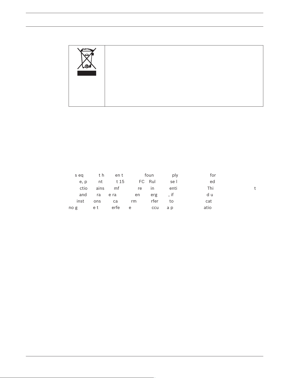
Disposal
Your Bosch product has been developed and manufactured using highquality materials and components that can be reused.
This symbol means that electronic and electrical devices that have reached
the end of their working life must be disposed of separately from
household waste.
In the EU, separate collecting systems are already in place for used
electrical and electronic products. Please dispose of these devices at your
local communal waste collection point or at a recycling center.
FCC information
This device complies with Part 15 FCC Rules. Operation is subject to the following two
conditions: (1) this device may not cause harmful interference, and (2) this device must
accept any interference received including interference that may cause undesired operation.
Changes or modifications not expressly approved by the party responsible for compliance
could void the user’s authority to operate the equipment.
This equipment has been tested and found to comply with the limits for a Class B digital
device, pursuant to Part 15 of the FCC Rules. These limits are designed to provide reasonable
protection against harmful interference in a residential installation. This equipment generates,
uses and can radiate radio frequency energy and, if not installed and used in accordance with
the instructions, may cause harmful interference to radio communications. However, there is
no guarantee that interference will not occur in a particular installation.
If this equipment does cause harmful interference to radio or television reception, which can
be determined by turning the equipment off and on, the user is encouraged to try to correct
the interference by one or more of the following measures:
1. Reorient or relocate the receiving antenna.
2. Increase the separation between the equipment and receiver.
3. Connect the equipment into an outlet on a circuit different from that to which the
receiver is connected.
4. Consult the dealer or an experienced radio/TV technician for help.
Robert Bosch (SEA) Pte Ltd Installation Guide 2014.03 | V1.0.0 | F.01U.277.701
8 en | System Overview ALLPLEX track Coordinator & Receiver
2
System Overview
The coordinator provides communication between the Central Console software and the many
receivers throughout the protected area. The receiver detects alarm signals from the
transmitter, and sends the signal to the coordinator either by wired RS-485 or through
wireless radio frequency. The coordinator forwards this information to the Central Console
software over wired Ethernet (TCP/IP), where the alarm will be processed accordingly. Each
coordinator (with its built-in receiver) also includes two analog inputs which support 4 state
supervised modes, and drivers for two relay outputs.
The receiver is designed to work with the Security Escort system throughout a protected area,
including building interiors. Each receiver contains a radio receiver to detect the transmissions
from transmitters, and a microcomputer to decode and interpret test and alarm messages.
Multiple receivers detect the same transmission and send the signal information to the
coordinator, so that the system can identify the transmitting information, including the device
and location. The receiver also monitors housing tampering and radio jamming, and reports
them to the coordinator.
Indoor coordinators/receivers are typically mounted on inside walls, and have one red and one
green LED. The green LED is used to indicate a successful test of a personal transmitter. The
red LED is illuminated during alarms. Each coordinator/receiver contains a piezo-electric
buzzer that can be activated if an alarm transmission is detected.
Outdoor coordinators/receivers are contained in small weatherproof boxes, typically mounted
on the sides of buildings and on light posts. Outdoor coordinators/receivers do not have the
visible red and green LED’s. For outdoors, the relay outputs can be connected to devices to be
used to acknowledge successful tests and alarms.
2014.03 | V1.0.0 | F.01U.277.701 Installation Guide Robert Bosch (SEA) Pte Ltd
ALLPLEX track Coordinator & Receiver Mounting the Device | en 9
3
3.1
3.1.1
Mounting the Device
Choose a mounting location based on the previous site survey. Mount the coordinator/receiver
as close as possible to the location found with the test coordinator/receiver. Use the following
sections as a guideline for coordinator/receiver mounting and spacing.
Indoor installation
Select a mounting location that:
– provides a clear line-of-sight of the protected area, if possible.
– is at least 31 cm (1 ft.) away from metal objects such as HVAC ducts.
– is on an inside wall, if possible.
– is 1.5 m to 1.8 m (5 ft. to 6 ft.) from the floor.
– is not at a barrier where it is important to resolve which side an alarm location is on.
– is not damaged by tampering or opening doors.
Spacing
Coordinator/receiver spacing should be no more than 25 m (80 ft.) between each coordinator/
receiver for standard construction. Range depends on the construction of the building. For
example, a building with hollow drywalls may support 25 m (80 ft.) spacing, but a building
with steel reinforced concrete may require reduced spacing. It is very important to maintain a
consistent spacing as this ensures optimum signal locating. The better the coordinator/
receivers can detect a transmitted signal, the more accurate the locating.
3.1.2
3.1.3
Mounting height
Mount coordinator/receivers 1.5 m to 1.8 m (5 ft. to 6 ft.) from the floor. Maintain a consistent
mounting height to ensure optimum signal locating. Do not place coordinator/receivers close
to the ceiling. This places them closer to the floor above reducing the floor-to-floor location
accuracy. It is also helpful to place the coordinator/receivers somewhat higher on the top floor
to be covered and somewhat lower on the bottom floor to be covered.
Multi-floor installations
Mount coordinator/receivers over one another in multi-floor installations. This helps maintain
proper floor-to-floor reception.
Figure 3.1: Coordinator/receiver locations
x
Robert Bosch (SEA) Pte Ltd Installation Guide 2014.03 | V1.0.0 | F.01U.277.701
Coordinator/Receiver location inside buillding
 Loading...