

Page 1
DS840LSN
EN
Installation Guide
TriTech PIR/Microwave
Intrusion Detector
Page 2
DS840LSN | Installation Guide | 1. General Information EN | 2
1. General Information
The DS840LSN is a microprocessor-based TriTech
Passive Infrared/Microwave Intrusion Detector.
Patented Passive Infrared and Microwave signal
processing provides excellent catch performance with
freedom from false alarms.
The DS840LSN can communicate and connect to all
LSN Bus Systems.
2. Specifications
Table 1: DS840LSN Specifications
Standby Power
LSN Supply Voltage
LSN Current
Consumption
Alarm Signal
Temperature
Microwave
Frequency
Coverage
Internal Pointability
Cover Tamper
Options
Patents
Compliance
DS840LSN 10.525 GHz (UL Listed)
DS840LSNC 10.588 GHz (UK, France)
Changes or modifications not expressly approved by
Bosch Security Systems can void the user's authority to
operate the equipment.
No internal standby battery. For each
hour of standby time needed, 4 mAh
are required. For UL Listed
Requirements, four hours (16 mAh)
are required.
33 V maximum
4.0 mA
Alarms are reported to the panel via
the LSN Bus.
-40°C to +49°C (-40°F to +120°F).
For UL Certificated Installations, the
temperature range is 0°C to +49°C
(+32°F to +120°F).
12 m x 12 m (40 ft. x 40 ft.)
+2° to –18° Vertical
Tamper signaling via LSN Bus
B335 Low Profile Swivel Mount
Bracket and B338 Ceiling Mount
Bracket. (The use of brackets may
reduce range and increase dead
zone areas.)
These detectors are covered under
one or more of the following U.S.
patents: #4,660,024, #4,764,755,
#5,077,548, #5,208,567,
#5,262,783, #5,450,062 and
#5,670,943.
Other patents pending.
This device complies with Part 15 of the
FCC Rules and with RSS-210 of Industry
and Science Canada. Operation is subject
to the following two conditions:
(1) This device may not cause harmful
interference, and
(2) This device must accept any interference
received, including interference that may
cause undesirable operation.
3. Mounting
3.1 Mounting Considerations
• Never install the detector in an environment that
causes a constant alarm in one technology; it
should never be left to operate with the LEDs in a
constant flashing green, yellow, or red condition. A
detector with one technology in constant alarm will
cause an alarm output whenever the other
technology alarms. Good installations start with the
LEDs OFF when there is no target motion.
• Point the unit away from outside traffic (for
example, roads, alleys, and parking lots).
Microwave energy will pass through glass
and most common non-metallic
construction walls.
• Avoid direct or indirect sunlight.
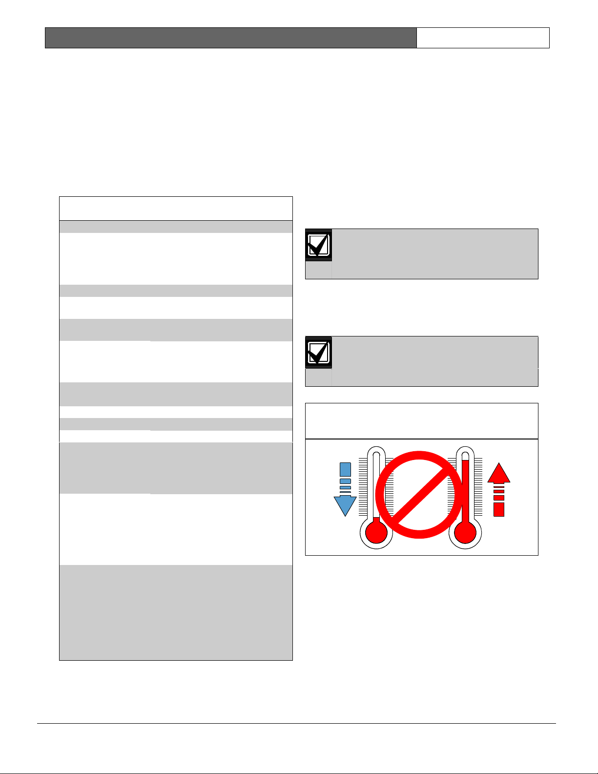
• Point the unit away from glass exposed to the
outdoors and objects that may change temperature
rapidly (see Figure 1)
The PIR detector will react to objects
rapidly changing temperature within its
field-of-view.
Figure 1: Avoid extreme temperature change
locations
• Eliminate interference from nearby outside
sources.
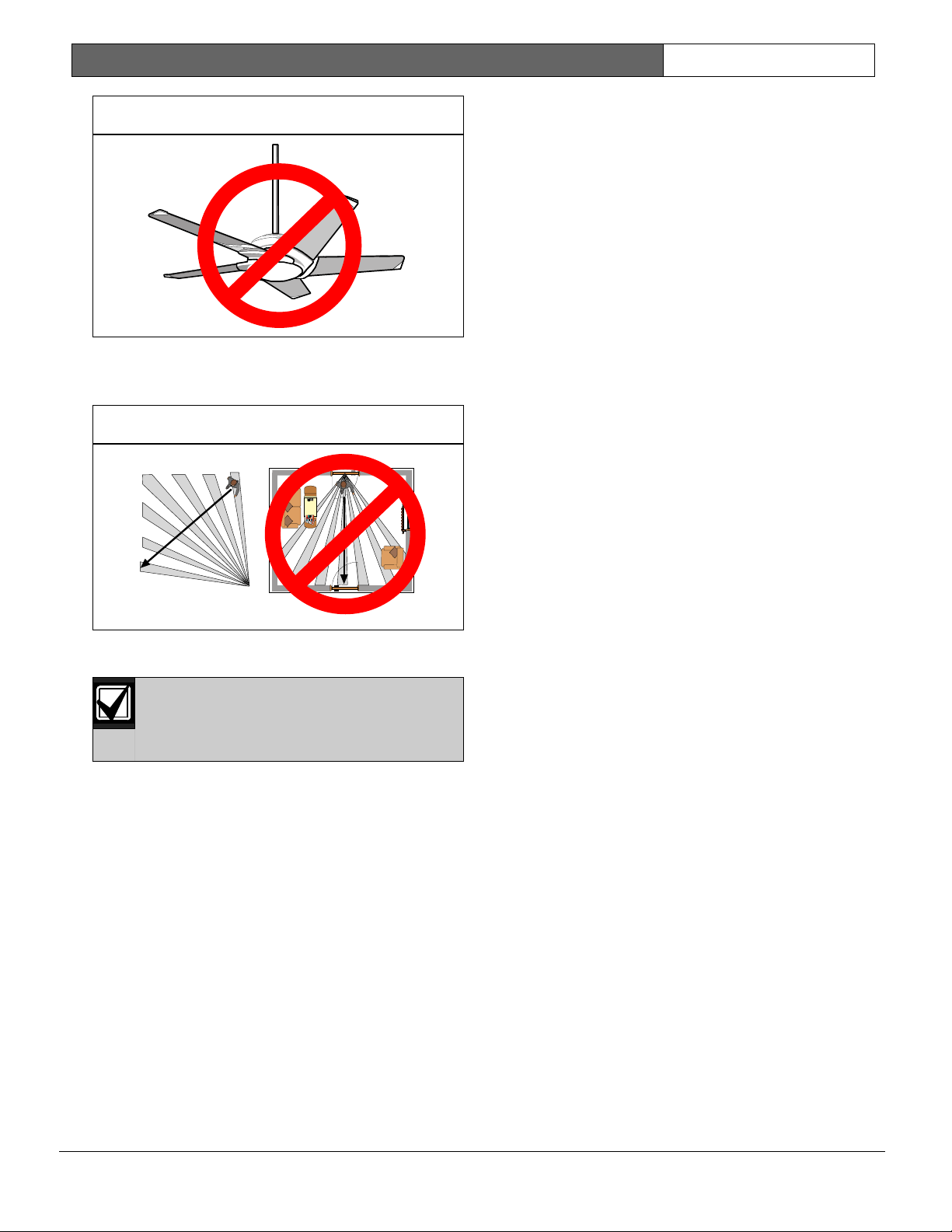
• Avoid installations where rotating machines (such
as ceiling fans) are normally in operation within
the coverage pattern (see Figure 2).
Bosch Security Systems | 9/03 | PRELIMINARY 4998132113Ar11
Page 3
DS840LSN | Installation Guide | 3. Mounting EN | 3
Figure 2: Avoid installing near rotating machines
• Select a location likely to intercept an intruder
moving across the coverage pattern (see Figure 3).
Figure 3: Coverage Pattern
Avoid mounting the detector in locations
(such as above a doorway) where people
can pass in close proximity (0.5 m / 1.5 ft.)
of the detector.
• The surface should be solid and vibration-free.
• Mounting height range is 1.8 m to 2.4 m (6 ft. to
8 ft.). The recommended height is 2.3 m (7.5 ft.).
Mounting height for Pet Applications is 2 m
(6.5 ft.).
Bosch Security Systems | 9/03 | PRELIMINARY 4998132113Ar11
Page 4
DS840LSN | Installation Guide | 3. Mounting EN | 4
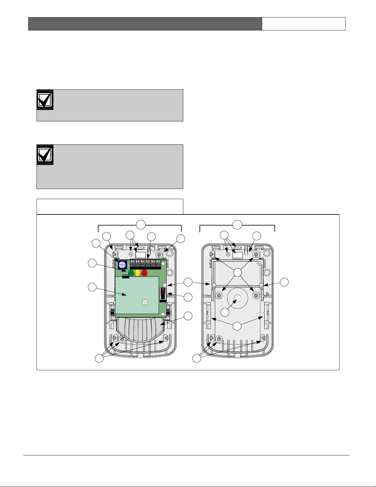
3.2 Mounting the Detector
See Figure 4 for location of features.
1. Remove the cover by inserting a thin flathead
screwdriver into the locking tab hole at the bottom
front of the detector, pressing in, and pulling the
cover up and forward.
Mount the unit with the terminal block up.
2. Remove the circuit board from the base by pulling
outward slightly on one of the Circuit Board
Locking Tabs (7).
Do not touch the mirror surface.
If you have touched the mirror surface
accidentally, be sure to carefully clean wipe
off fingerprints with a clean cloth and a mild
non-abrasive cleaning solution.
Figure 4: Location of Features
3. Remove the Mirror Assembly (9).
Carefully press with two fingers on the top end of
the mirror assembly (9) and slide it out of the
spring loaded tracks (11).
4. Break away the needed Wire Knockouts for the
wire entrance (4).
5. Open two holes for surface or corner mounting
(13).
6. Mark the location for the mounting screws using
the enclosure as a template.
7. Pre-start the mounting screws.
8. Route wiring as necessary (see Section 4. Wiring).
Route to the rear of the base and through the wire
entrance. Make sure all wiring is unpowered
before routing.
9. Securely attach the base to the mounting surface.
10. Return the circuit board to the base.
11. Install the mirror using settings in Table 3.
1 2
11
3
6
8
13 13
4 4
5
13
1 - Inside view (circuit board and mirror assembly
mounted)
2 - Inside view (no circuit board and mirror assembly
mounted)
3 - Microwave Range Adjustment
4 - Wiring Knockouts
5 - Terminal Block (T-strip)
6 - LEDs (green, yellow, red)
14
13
77
8
9
10
11
7 - Circuit Board Locking Tab (One on each side)
8 - Tamper Switch
9 - Mirror Assembly
10 - Microwave Board
11 - Mirror Tracks (2)
12 - Bracket Mounting Hole
13 - Mounting Hole Knockouts
14 - Cable Tie Strain Relief
Bosch Security Systems | 9/03 | PRELIMINARY 4998132113Ar11
Page 5

DS840LSN | Installation Guide | 4. Wiring EN | 5
4. Wiring
Apply power ONLY after all connections
have been made and inspected. Do NOT
coil excess wiring inside the detector.
Figure 5: DS840LSN Terminals
1 2 3 4
1 - aLSN1 & bLSN1: coming from the preceding
LSN element. Shielded cable is recommended
for bus connections
2 - aLSN2 & bLSN2: going to the next LSN
element. Shielded cable is recommended for
bus connections.
3 - 5 & 6: Spare terminals.
4 - 7: Connection for ground wire from shielded
cable.
Do not coil excess wire inside the
enclosure.
Plug the wire entrance hole with the foam
plug provided after all wiring connections
have been made.
5. LED Operation
The detector uses 3 colored LEDs to indicate the
various alarm and supervision trouble conditions that
that exist. See Table 2.
Table 2: Status of LEDs
Walk
Test
Status Condition Red Yellow Green
Disabled All Off Off Off
Enabled
Power-Up Sequential Green, Yellow, Red
Flashing
Dual Alarm Flashing Off Off
Microwave
Alarm
PIR Alarm Off Off Flashing
No Activity Off Off Off
Off Flashing Off
During walk testing, the LEDs light for the first
technology (microwave or PIR) and then light red to
indicate a detector alarm. The LEDs will not indicate
activation of the second technology with color.
If the detector experiences a Microwave or PIR self-test
failure, it is in need of replacement.
6. Mirror Alignment
1. Select the vertical mirror angle from Table 3 to
match the mounting height and desired maximum
coverage.
Table 3: Broad Coverage Mirror
Maximum Coverage DistanceMounting
Height
2.0 m (6.5 ft.)
2.3 m (7.4 ft.)
2.6 m (8.5 ft.)
* = Required Settings for Pet Applications
2. The angle adjust markings are on the mirror. Push
in on the bottom or top of the mirror assembly to
position the angle hash marks with the markers on
each side of the frame (Figure 6) based on the
values in Table 3.
7.5 m (25 ft.) 12 m (40 ft.)
-6° * -4° *
-10° -8°
-12° -8°
Bosch Security Systems | 9/03 | PRELIMINARY 4998132113Ar11
Page 6

DS840LSN | Installation Guide | 7. Walk Test EN | 6
Figure 6: Mirror Adjustment Markings
1
1 - Adjust frame marks
3. See Section 10. Using Pet Immunity for Pet Applications
7. Walk Test
1. Wait at least two minutes, after applying power, to
start walk tests.
During the warm-up period, the LEDs will
flash red, yellow and green until the unit
stabilizes (approximately one to two
minutes) and has not registered movement
for two seconds. When the LEDs stop
flashing, the detector is ready to be tested.
With no motion in the protection area, the
LEDs should not be flashing. If the LEDs
are flashing, recheck the protection area for
disturbances affecting the microwave
(yellow) or PIR (green) technologies.
7.1 Establishing PIR Pattern Coverage
1. Enable Walk Test via the keypad.
2. Turn the Microwave range adjust to minimum
(counter-clockwise) and replace the cover.
Figure 7: Microwave Range Adjustment
The center of the pattern should be pointed
toward the center of the intended
protection area.
6. If the desired coverage cannot be achieved, try
angling the coverage pattern up or down to assure
the pattern is not aimed too high or low.
7.2 Establishing Microwave Coverage
Wait one minute after removing/replacing
the cover so the microwave portion of the
detector can settle. Wait at least ten
seconds between the following walk testing
procedures.
1. Enable Walk Test via the keypad.
2. The LEDs should be OFF before walk testing.
3. Walk test across the pattern at the intended
coverage’s farthest end. Start walking from outside
the intended protection area and observe the 3
colored LEDs. The edge of the microwave pattern
is determined by the first yellow, microwave
activation of the LEDs (or the first red activation if
the LEDs show green first).
4. If adequate range can not be reached, increase the
Microwave Range Adjust slightly. Continue walk
testing (waiting one minute after
removing/replacing the cover) and adjusting the
range until the farthest edge of desired coverage
has been accurately placed.
Do not adjust the microwave range higher
than required. Doing so will enable the
detector to catch movement outside of the
intended coverage pattern.
5. Walk test the unit from all directions to determine
all the pattern boundaries.
7.3 Verify Detector Coverage
The LEDs should be OFF before walk testing.
3. Walk test across the pattern at its farthest edge,
then several times closer to the detector. Start
walking from outside of the intended protection
area, and observe the three colored LEDs. The
edge of the pattern is determined by the first green
PIR activation of the LEDs (or the first red
activation if the yellow microwave LED activates
first).
4. Walk test from the opposite direction to determine
both boundaries.
5. While standing 3 m to 6 m (10 ft. to 20 ft.) from
the detector, slowly bring your arm up and into the
pattern to mark the lower boundary on PIR alarm.
Repeat from above for the upper boundary.
Bosch Security Systems | 9/03 | PRELIMINARY 4998132113Ar11
1. Walk test the unit from all directions to determine
the detection boundaries. A detector alarm is
signaled by the first red activation of the 3 colored
LEDs after an initial green or yellow activation.
Page 7

DS840LSN | Installation Guide | 8. Supervision Features EN | 7
8. Supervision Features
The supervision features function as follows:
• PIR/Microwave: The complete circuit operation
of these subsystems is checked approximately
every 12 hours. If the PIR or microwave subsystem
fails, this will be communicated to the control
panel.
• Default: The detector will default to PIR
technology protection if the microwave subsystem
fails.
9. Other Information
• Maintenance: At least once a year, the range and
coverage should be verified. To ensure continual
daily operation, the end user should be instructed
to walk through the far end of the coverage
pattern. This ensures an alarm output prior to
arming the system.
• Pattern Masking: The PIR coverage pattern may
be masked using masking tape or electrical tape on
the inside of the mirror.
Many adhesives will either destroy the
mirror surface or leave enough residue
behind to degrade the coverage
performance. Be sure to clean the mirror
surface with a mild window cleaning
solution after masking removal.
10. Using Pet Immunity
The DS840LSN detector provides reasonable
protection from nuisance alarms caused by the
following sources:
• One dog up to 27 kg (100 lbs.)
• Up to 10 cats
• Multiple small rodents, such as rats
• Random flying birds
The Pet Filter is not a mirror mask. Use only
the supplied filter for pet applications.
To take full advantage of the Pet Immunity feature, the
following steps should be followed:
1. Add the Pet Filter to the mirror (included in the
hardware bag). See Figure 8.
Figure 8: Applying the Pet Filter
1
2
Masking only eliminates the PIR portion of
the coverage and has no affect on the
microwave pattern.
Add the Pet Filter for pet applications only.
1 - Pet Filter
2 - Mirror Assembly
2. Mount the detector 2 m (6.5 ft.) high and adjust the
Mirror angle as in Section 6. Mirror Alignment.
3. Mount where the animals can not come within
1.8 m (6 ft.) of the detector by climbing on
furniture or other objects.
4. Adjust the microwave range for the minimum
acceptable coverage for the room in which the
detector is installed.
Pet immunity is only available when using
the filter provided with the detector. This
pet nuisance protection has not been
verified by Underwriters Laboratories, Inc
Bosch Security Systems | 9/03 | PRELIMINARY 4998132113Ar11
Page 8

DS840LSN | Installation Guide | 11. Coverage Patterns EN | 8
11. Coverage Patterns
The protected coverage area is where the microwave
and PIR patterns overlap (indicated in Figure 10 and
Figure 11 in light gray).
Numbered callouts in Figure 10 and Figure 11 below
correspond to the mirror segments in Figure 9.
Figure 9: Mirror Segments
15
10
1 2 3 4 5 6 7 8 9
11
16
12
17
13
14
Figure 11: Coverage Pattern – Side View
10
6.5
F
e
e
t
Meters
0
0
Feet
0
12
40
3
M
e
2
t
e
r
s
0
15-17 10-14 1-9
Coverage patterns are based on a detector mounting
height of 2.0 m (6.5 ft.)t
Figure 10: Coverage Pattern – Top View
Meters
0
20
15
F
e
0
e
t
17
16
20
Feet
0
10
10
14
14
2
1
11
12
13
8
8
12
6
4
4
3
3
M
e
t
0
5
5
e
r
s
7
7
6
6
9
9
40
6
Coverage patterns are based on a detector mounting
height of 2.0 m (6.5 ft.)t
Bosch Security Systems | 9/03 | PRELIMINARY 4998132113Ar11
Page 9

DS840LSN | Installation Guide | 11. Coverage Patterns EN | 9
Bosch Security Systems | 9/03 | PRELIMINARY 4998132113Ar11
Page 10

DS840LSN | Installation Guide | 11. Coverage Patterns EN | 10
Bosch Security Systems | 9/03 | PRELIMINARY 4998132113Ar11
Page 11

DS840LSN | Installation Guide | 11. Coverage Patterns EN | 11
Bosch Security Systems | 9/03 | PRELIMINARY 4998132113Ar11
Page 12

DS840LSN | Installation Guide | 11. Coverage Patterns EN | 12
Bosch Security Systems | 9/03 | PRELIMINARY 4998132113Ar11
Page 13

DS840LSN | Installation Guide | 11. Coverage Patterns EN | 13
Bosch Security Systems | 9/03 | PRELIMINARY 4998132113Ar11
Page 14

DS840LSN | Installation Guide | 11. Coverage Patterns EN | 14
Bosch Security Systems | 9/03 | PRELIMINARY 4998132113Ar11
Page 15

DS840LSN | Installation Guide | 11. Coverage Patterns EN | 15
Bosch Security Systems | 9/03 | PRELIMINARY 4998132113Ar11
Page 16

Bosch Security Systems
130 Perinton Parkway
Fairport, NY 14450-9199
Customer Service: (800) 289-0096
Technical Support: (888) 886-6189
© 2003 Bosch Security Systems
PRELIMINARY 4998132113Ar11
 Loading...