

Page 1
Installation Instructions
RF835 TriTech®
Microwave/PIR Intrusion Detector
with Pet Immunity
1.0 Overview
The RF835 TriTech® detector uses passive infrared technology, Microwave technology, and artificial intelligence to detect motion and provides freedom from false alarms. When motion is detected the unit
sends an alarm signal to the control panel.
2.0 Specifications
General
Power supplied by four 1.5V AA Alkaline Batteries.
•
• Typical current draw is 100 micro-amps with LED disabled.
• Typical battery life is two to three years (has not been verified by
Underwriters Laboratories).
• Operating temperature range of +32°F to +120°F (0°C to +49°C)
• Microwave Frequency: 10.525 Ghz (U.L. Listed)
• RF Transmit Frequency: 304.00 MHz
• Options: Low Profile Swivel Mount Bracket (use of this bracket may
reduce range and dead zone areas).
TriTech Motion Sensor
• Coverage area 35 ft. by 35 ft. (10.7 m by 10.7 m)
• Internal coverage pointability -6° to -10° Vertical and ±10° Horizontal.
• Masking kit provided to block portions of coverage area.
• Field selectable sensitivity options of Standard and Intermediate.
• Three minute transmitter lockout time after alarm extends battery life.
• Timed Walk Test Mode automatically disables LED after setup to extend
battery life.
• Cover activated Tamper indication. Optional wall activated Tamper is
included.
• Pet Immunity capabilities have not been verified by UL.
RF Transmitter
• Integral RF transmitter capable of transmitting 500 feet open air. (Actual
acceptable transmitter range should be verified for each installation).
• Transmits low battery report (trouble) to the control panel.
• Transmits tamper
• Transmits supervisory signal to the control panel every 64 minutes.
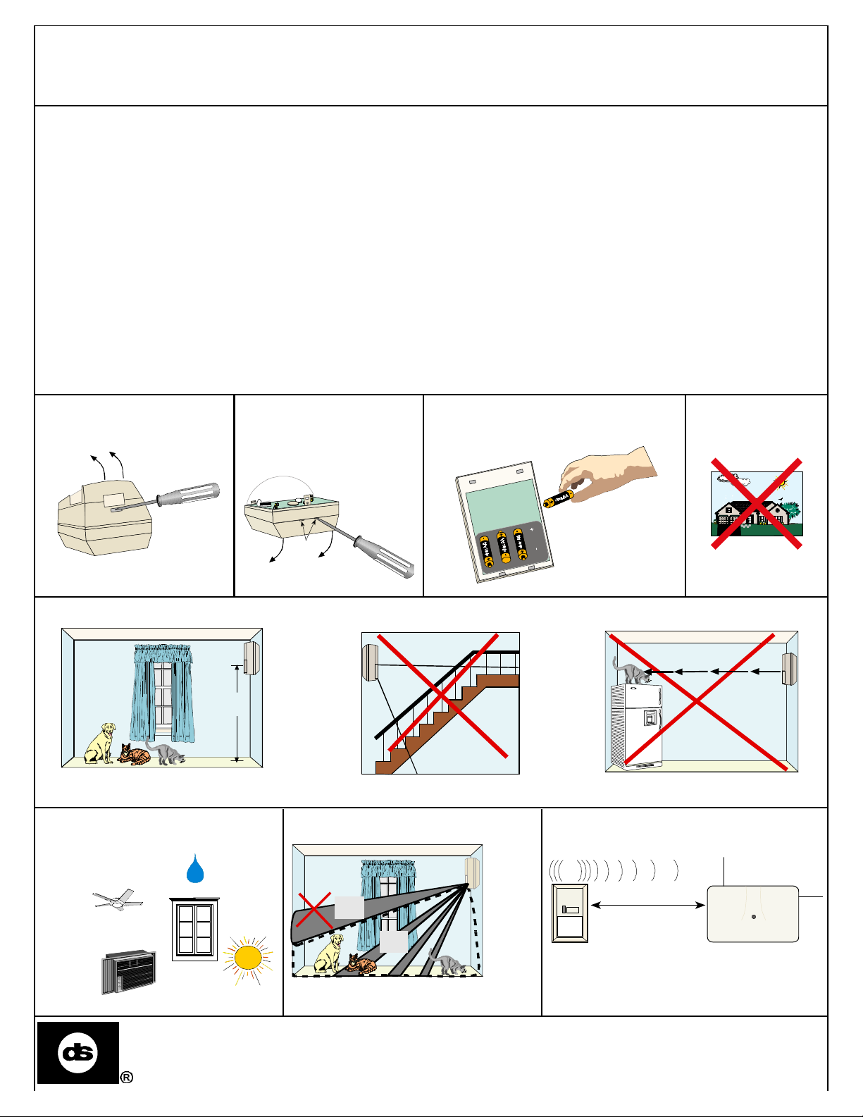
3.0 Installation
3.1 Open the cover 3.2 Open base 3.3 REMOVE BATTERY PLUG
Insert
screwdriver
into notches
and gently
twist to open
Notches
Insert four (4)
size AA Alkaline
batteries in the
battery holder per
the guides imprinted
on the holder
3.4 Select a mounting location
DO NOT MOUNT
OUTDOORS
3.5 Observe the Pet Immunity mounting recommendations
Don't
point
at
6.5 Ft
(2 M)
stairs
Mount the detector 6 1/2 feet
(2 meters) above the floor
3.6 Avoid:
Moving objects
Hot or cold air
directed onto
sensor
Moisture
Direct or
reflected
sunlight
3.7 Observe the Pet Immune Area 3.8 Observe Receiver Range
NO
OK
Pet Immune Area
NO
Upper
areas
are
not
pet
immune
Don't
point
where
pets
can
climb
NO
500’ max
(300 meters)
Panel Receiver
Detection Systems, Inc., 130 Perinton Parkway
Fairport, New York, USA 14450-9199
(716) 223-4060 • (800) 289-0096 • Fax: (716) 223-9180
PRELIMINARY
7/99
Copyright © 1999 Detection Systems, Inc.
RF835 Installation Instructions P/N 40142A
Page 2
Page 2 Copyright © 1998 Detection Systems, Inc. RF835 TriTech Installation Instructions
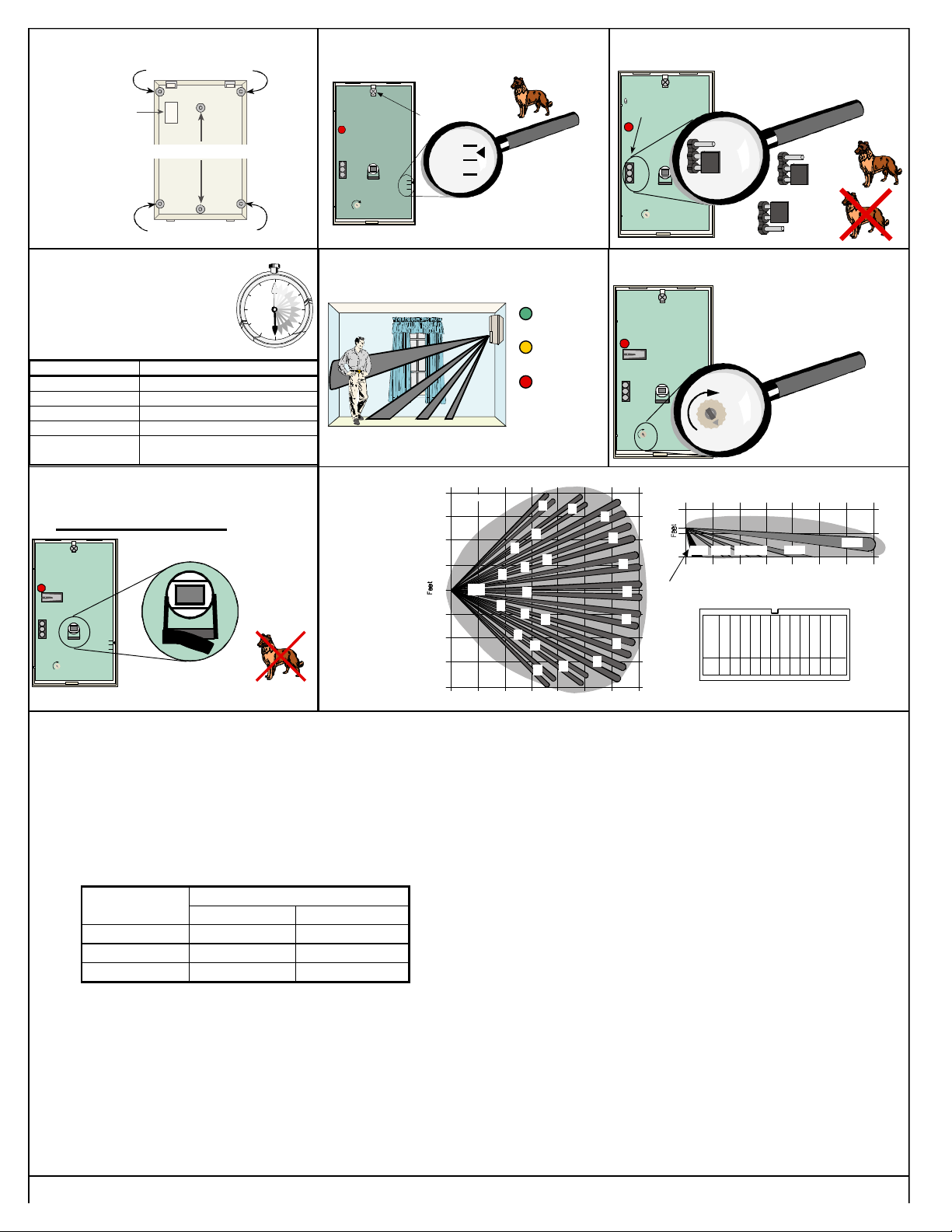
3.9 Mount the Detector 3.10 Set the Vertical Adjust 3.11 Set the PIR Sensitivity
Thinwall
breakaway for
wall tamper
switch
Corner mount
Flush mount
Corner mount
PIR
Sensitivity
Vertical Adjust Screw
INT
STD
MAX
MIN
MW
- 6
- 10
- 6
- 10
Adjust the board to - 5
(Refer to section 5.0)
Loosen
the Vertical
Adjust Screw.
Selection Pins
INT
STD
MAX
MIN
MW
For pet applications,
set jumper to STD.
INT
STD
- 6
- 10
INT
STD
INT
STD
3.12 LED Operation
3.13 Walk Test
Replace cover
Wait 30 minutes after installing
batteries to begin Walk test.
LED Condition Cause
Steady Red Unit Alarm
Steady yellow Microwave Activation (walk test)
Steady Green PIR Activation (walk test)
Flashing Red Warmup Period After Power-Up
Flashing Red (four-
pulse sequence)
3.15 Uncover Look Down Lens
In non-pet applications only
INT
STD
MW
- 6
- 10
MAX
MIN
Microwave or PIR failure.
Replace Unit.
, if look-down is
desired, peel away the
look-down mask.
Do not remove
the clear
plastic
Peel away
the mask
3.16 Coverage
lens.
Patterns
Meters
0
20
TOP VIEW
15
10
5
0
5
10
15
20
0 5 10 15 20 25 30 35
Feet
4.0 Programming
See your Control Panel Programming Guide for information.
5.0 Setup for Non-Pet Applications
Select the vertical starting angle from the chart. To adjust the vertical
starting angle for the desired mounting height and range, loosen
the vertical adjust screw and slide the board up, to point the PIR
pattern down. Note the settings on the vertical adjust scale (Figure
3.9).
Mounting Range
Height
6.5 ft. (2 m)* -7 -5*
7.0 ft. (2.1 m) -9 -6
8.0 ft. (2.4 m) -10 -7
* Required for pet immunity.
NOTE: The vertical angle must be set at -5° for installations contain-
ing pets.
NOTE: During the warm-up period, the tricolor LED will flash red until
the unit has stabilized (approximately 30 minutes) and has
seen no movement for two seconds. When the LED stops flashing, the detector is ready to be tested. With no motion in the
protection area, the LED should be OFF. If the LED is on, recheck the protection area for disturbances affecting the Microwave (yellow) or PIR (green) technologies. (See Figure 3.11.)
20 ft. (6.1 m) 35 ft. (10.7 m)
3.14 Adjust the Microwave
Set Microwave to MIN
Green =
PIR detect
Yellow =
MW detect
Red =
Alarm
1.6 3.2 4.8 6.4 8 9.6 11.2
B
C
N
R
O
S
W
LZ
Z
X
T
P
U
Q
K
L
INT
STD
MAX MIN
MIN
Meters
0
1.6 3.2 4.8 6.4 8 9.6351
10
D
SIDE VIEW
E
F
G
0
0 5 10 15 20
Feet
Remove masking for Look Down zone.
H
I
J
RF835 TriTech Lens
Pattern Testing in Walk Test Mode
Removing and replacing the cover will start a 90 second Walk
Test Mode. During this Test Mode, any activity in the sensor’s coverage pattern will cause a transmitted alarm and LED activation.
Each alarm will also extend the Test Mode for an additional 90
seconds.
If necessary,
adjust the Microwave
MAX
Set as low
as possible for
normal operation
N-QR-U,ZW-XLZ
BCDE FGH I J KL
NRWSOZ P T X UQ
B-L
30
25
6.0 Other Information
Maintenance: At least once a month, the range and coverage
should be verified using the walk test mode. To ensure continual
daily operation, the end user should be instructed to walk through
the far end of the coverage pattern. This ensures an alarm output
prior to arming the system.
Pattern Masking: The PIR coverage pattern may be masked
using the masking stickers provided with the unit.
NOTE: Masking only eliminates the PIR portion of the coverage
and has no effect on the Microwave pattern.
U.S. Patent Numbers: #4,660,024, #4,764,755, #5,077,548,
#5,208,567, #5,262,783, and #5,450,062. Other patents pending.
FCC Notice
This device complies with Part 15 of the FCC Rules and with RSS-210 of
Industry and Science Canada. Operation is subject to the following two conditions: (1) this device may not cause harmful interference, and (2) this
device must accept any interference received, including interference that
may cause undesirable operation. Changes or modifications not expressly
approved by Detection Systems, Inc. can void the user's authority to operate
the equipment.
-5°
 Loading...