


VT 3000

1/8
Analog amplifier
Type VT 3000
Component series 3X
RE 29935/10.12
Replaces: 11.06
Overview of contents Features
– Suitable for the control of pilot operated proportional direc-
tional valves (type .WRZ, up to component series 6X) and
direct operated proportional pressure valves (type DBEP6
and 3DREP6, each component series 1X) without electrical
position feedback
– Four command values adjustable with potentiometers
– Four command value call-ups with LED display
– Differential input
– Step function generator
– Ramp generator
– Two pulsed current output stages
– Polarity protection for the voltage supply
Note:
When supplied the amplifiers have a ramp time of 5 s (setting
of the ramp time of 1 s see page 6).
Contents Page
Features 1
Ordering code 2
Functional description 2
Block circuit diagram / pin allocation 4
Technical data 5
Output curve 6
Indicator / Adjustment elements 6
Unit dimensions 7
Engineering notes / maintenance instructions /
supplementary information 7
H4162
similar figure
5 K
10c (10a, 8a, 12a)
20c +9 V
20a M0
26a
5 K
5 K
10c (10a, 8a, 12a)
26c –9 V
20a M0
26a
10c (10a, 8a, 12a)
20c +9 V
26c –9 V
26a
2/8 Bosch Rexroth AG Hydraulics VT 3000 RE 29935/10.12
Ordering code
Amplifier for prop. directional valves (type .WRZ, up to
component series 6X) and prop. pressure valves (type
DBEP6 and 3DREP6, each component series 1X)
Component series 30 to 39 = 3X
(30 to 39: unchanged technical data and pin allocation)
Further details in plain text
VT 3000 3X
*
Functional description
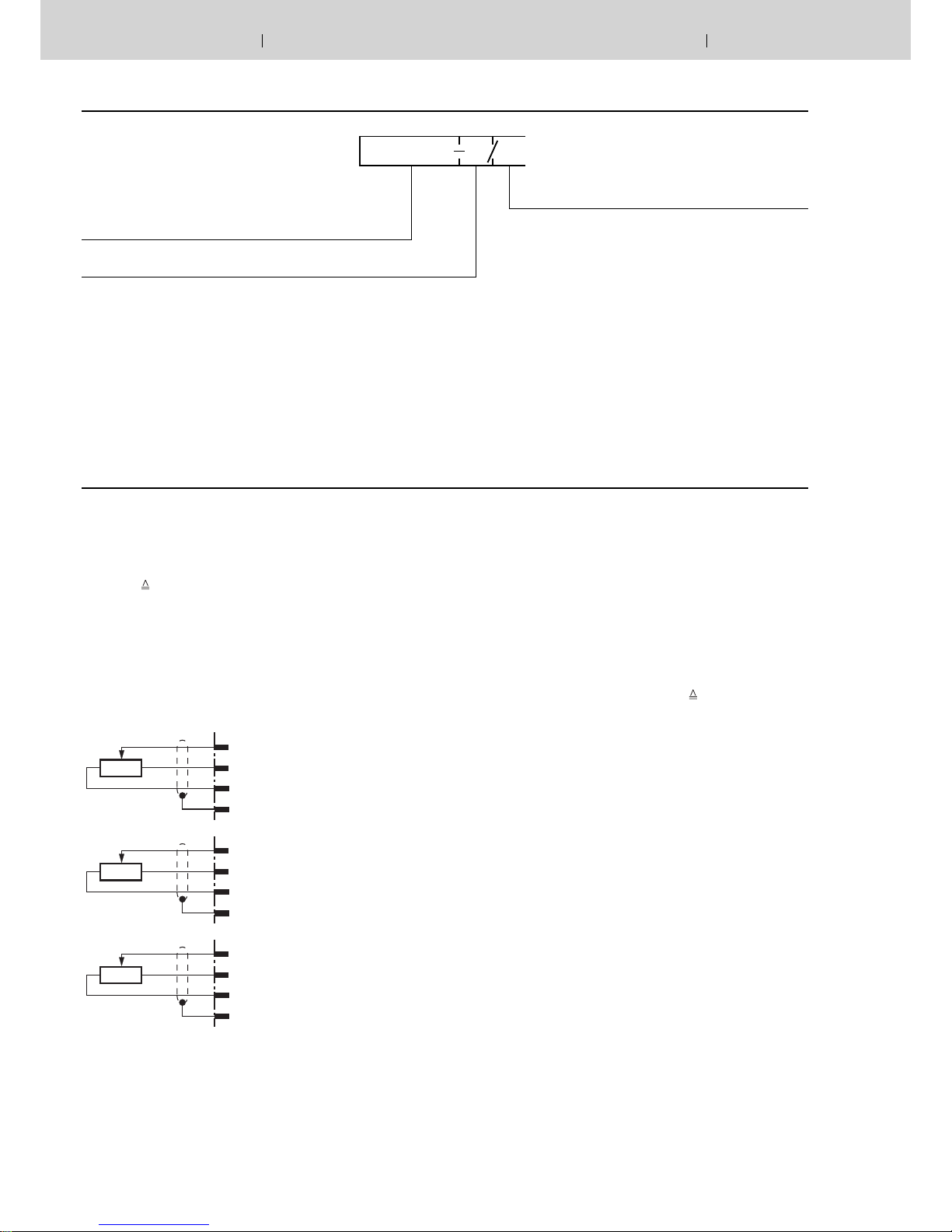
With the command value inputs 1 to 4 command values can
be called up [1] by operating the corresponding relays (K1
to K4). The command value voltage is either given directly
through the controlled voltages ±9 V of the power supply [10]
or via an external command value potentiometer. For this inputs ±9 V
±100 % 1) is valid. If these four command value
inputs are directly connected to the controlled voltages ±9 V
four different command values can be set at the potentiometers „w1“ to „w4“. When using external command value potentiometers at these inputs the internal potentiometers also
function as weakeners or limiters when these are not set to
maximum.
External command value potentiometer
Inputs
Control
solenoid „B“
Inputs
Control
solenoid „A“
Inputs
Control
solenoid
„A“ and “B“
Which command value is momentarily called up is indicated
by the LEDs „H1“ to „H4“. If more than one command value
is called up simultaneously the input with the highest number has priority. Example: If command value 1 and command
value 3 are activated simultaneously the command value 3
becomes effective.
A further output of the card provides a supply voltage for the
command value call-ups which can be switched over from
+9 V to –9 V with the relay K6
1)
.
All relays on the card are switched with 24 VDC (smoothed).
Additionally, the direct command value input 5 is available for
the input voltage 0 to ±6 V. Valid is ±6 V
± 100 % 1).
The command value input 6 is a differential input (0 to ±10 V).
If the command value is presented by a separate electronics
with a different reference potential this input must be used.
When switching on or off the command value it must be taken
care that both signal lines are either separated from or connected to the input.
All command values are summated with the correct value and
sign before they are connected further [3].
The added ramp generator [4] produces a ramp-like output
signal from the jump-like given input signal. The time constant
can be set with the potentiometers „t1“ to „t5“. The ramp time
given refers to a command value jump of 100 % and can be,
according to the setting through the selection via jumpers (J5,
J6), approximately 1 s or 5 s. If a command value jump smaller than 100 % is switched to the input of the ramp generator
the ramp time shortens appropriately.
Card holder:
– Type VT 3002-1-2X/32D, see data sheet 29928
Single card holder without power pack
1)
Reference potential for the command values 1 to 5
is M0 (measuring zero)
Hydraulics Bosch Rexroth AGRE 29935/10.12 VT 3000
3/8
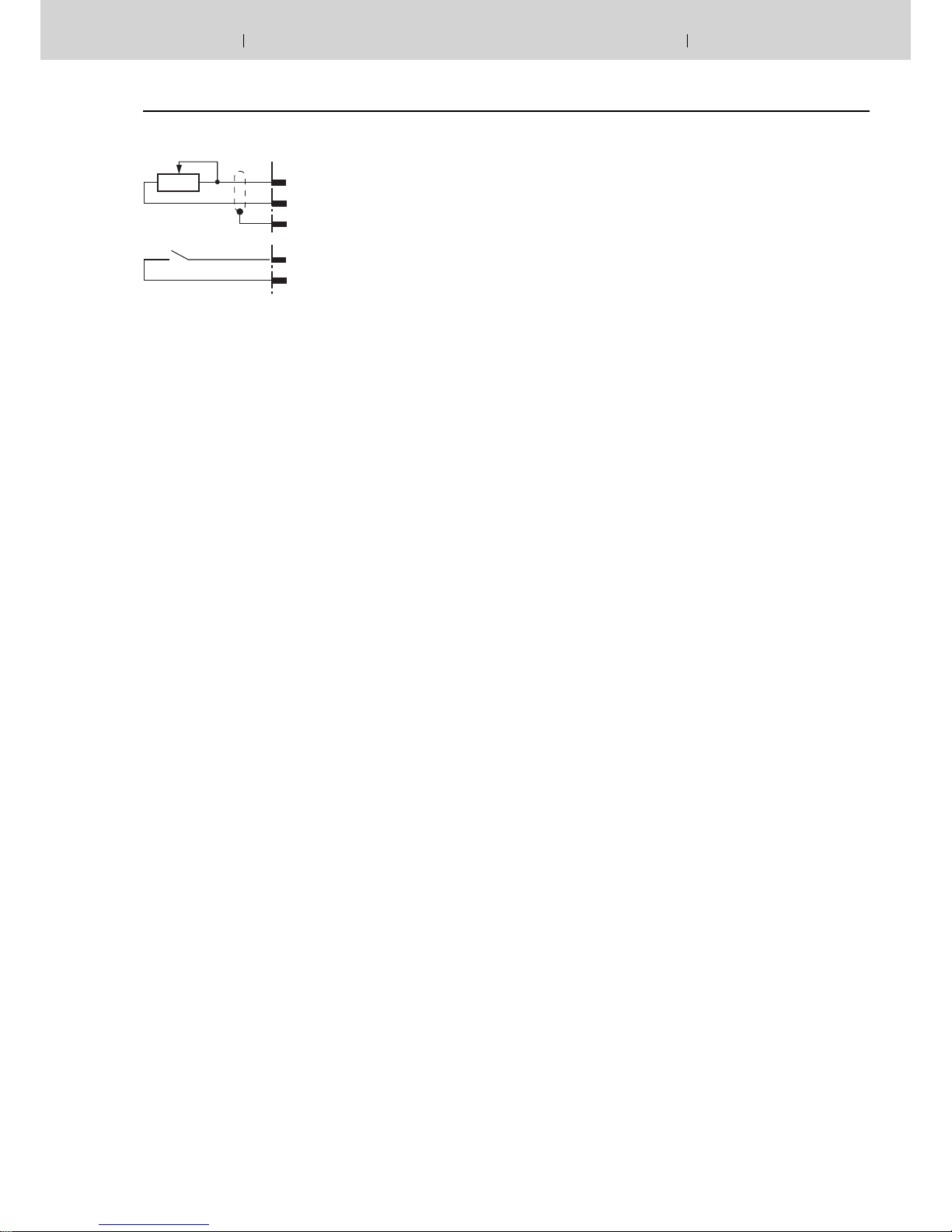
Note:
When using an external time potentiometer the internal
potentiometer for the ramp time must be set at maximum.
The maximum ramp time decreases because the resistance of the external potentiometer is connected parallel to
the internal potentiometer (approx. 500 kΩ)!
By switching the relay K5 or through an external bridge the
ramp time is set to its minimum value (approx. 30 ms).
The output signal of the ramp generator [4] runs parallel to
the summator [6] and the step function generator [5]. On command values > ±1 % the step function generator produces a
polarity-dependent constant step signal with the command
value voltages which is added to the output signal of the
ramp generator. This step function causes the rapid travelling
across the overlapping area of the valve spool.
Functional Description (Continuation)
The output signal of the summator [6] is the command current
value and is led to the two current output stages [7] and to the
test point „W“ on the front plate of the card. A voltage of +6 V
at the command value test point „W“ corresponds to a command value of +100 %.
A positive command value signal at the input of the amplifier
controls the output stage for solenoid „B“, a negative command value signal the output stage for solenoid „A“. If the
command value signal is smaller than ±1 % (step function still
ineffective) a pilot current of 20 mA flows through both solenoids. The actual values of the currents through the two solenoids can be measured separately at the test points „I
A
“ (so-
lenoid „A“) and „I
B
“ (solenoid „B“). Here a current of 800 mA
corresponds to a voltage of 800 mV.
LED „H11“ lights up when the system is powered up.
LED „H12“ („Ready for operation“) lights up to indicate trouble-free operation as long as:
– the internal power supply (±9 V) is functioning properly
– there is no short-circuit in the solenoid lines
In the event of a fault, both output stages are immediately deenergized and the signal „Ready for operation“ is cancelled.
Once the fault has been cleared, the amplifier card is immediately operable and LED „H12“ lights up again.
[ ] = Allocation in block circuit diagram page 4
External time potentiometer and ramp „Off“
14a
14c
26a
500 K
14a
14c
Ramp „controllable“
min. time at 0 Ω
max. time at 500 kΩ
Ramp „on/off“
 Loading...