

Page 1

Scaldacqua elettrici - a legna - bollitori - serbatoi
Electric water heaters - Wood water heaters - Boilers - Tanks
Scaldacqua elettrici
Pompe di calore
Pompa di calore.
HEAT PUMP.
pag. 2
Scaldacqua elettrici
con basamento
uso domestico.
ELECTRIC WATER HEATERS
WHIT BASE FOR DOMESTIC USE.
pag. 12 pag. 14
Scaldacqua elettrici
verticali a parete
a risparmio energetico.
VERTICAL ELECTRIC WALL WATER
HEATERS WHIT ENERGY SAVINGS.
pag. 4
Scaldacqua elettrici
verticali con basamento
uso commerciale.
VERTICAL ELECTRIC WATER HEATERS
WHIT BASE FOR COMMERCIAL USE.
Scaldacqua elettrici
verticali a parete.
VERTICAL ELECTRIC WALL
WATER HEATERS.
pag. 6 pag. 8 pag. 10
Scaldacqua a legna.
WOOD WATER HEARTERS.
pag. 16 pag. 18
Scaldacqua elettrici
orizzontali a parete.
ORIZONTAL ELECTRIC WALL
WATER HEATERS.
Serbatoi e bollitori.
TANKS AND BOILERS.
pag. 18-25
Scaldacqua elettrici
rapidi a parete.
RAPID ELECTRIC WALL
WATER HEATERS.
Serbatoi per acqua
refrigerata e
acqua calda.
COOLED WATER TANKS
AND HOT WATER TANKS.
BOSCHETTI INDUSTRIE MECCANICHE s.r.l.
www.boschettindustriemeccaniche.it
vendite@boschettindustriemeccaniche.it
Page 2
BOSCHETTI:
LA RISCOPERTA DELL’ACQUA
CALDA
Oltre 50 anni di attività hanno consentito alla Boschetti di
realizzare una vastissima gamma di prodotti secondo i più
aggiornati standards europei per: rendimento, qualità e design.
Sono scaldacqua ad accumulo elettrici, gas, legna e bollitori
adattabili alle diverse esigenze dell’utenza. L’impegno continuo
dell’Azienda nell’utilizzo delle tecnologie più avanzate e nella
ricerca costante verso una produzione attenta sia all’ambiente
che al risparmio energetico, l’hanno portata a diventare uno dei
più importanti punti di riferimento nei mercati di tutto il mondo.
Questo catalogo è rivolto agli operatori del settore, è uno
strumento di facile consultazione per conoscere ed apprezzare
l’intera produzione Boschetti.
BOSCHETTI:
THE NEW DISCOVERY OF HOT
WATER
Over 50 years of experience allowed Boschetti to create a
wide range of products in according to the latest european
standards for: efficiency, quality and design.
These products are: electric, gas, wood water heaters and
boilers adapted to the different customer’s needs.
The company is one of the most important landmark in the
world markets, thanks to advanced technologies, attention to
the environment and energy saving.
This catalogue, easy to consult, is addressed to the sectorial
operators, in order to know and appreciate all Boschetti
production.
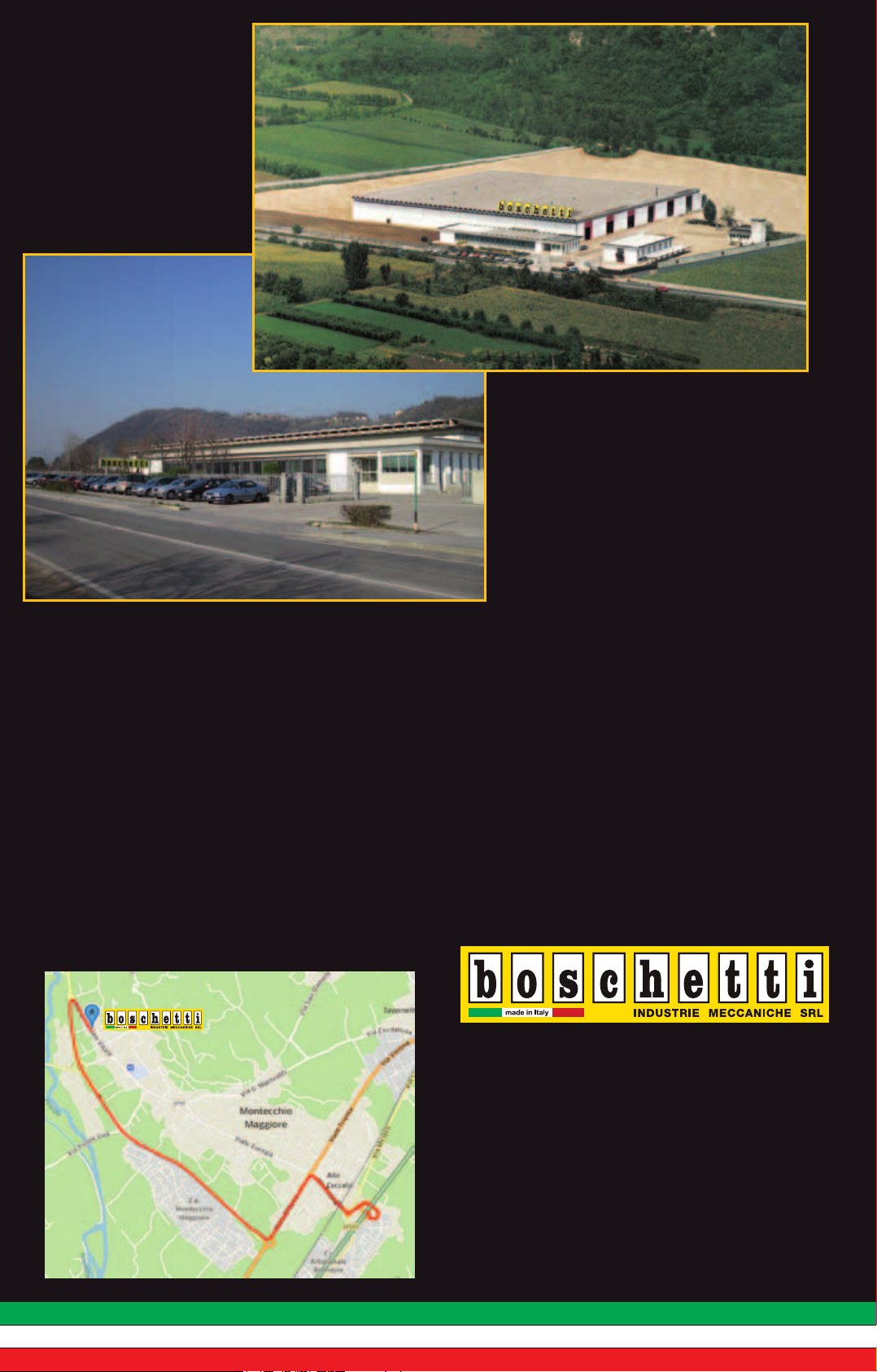
Via Bivio S.Vitale, 58
36075 Montecchio Maggiore (VI)
Tel. +39 0444.490636
Fax +39 0444.490496
Autostrada A4 (Milano - Venezia)
uscita Montecchio Maggiore
▼
Seguire strada per Valdagno.
A km. 5 dall’uscita dell’autostrada,
sulla destra, alla fine del paese,
c’è la nostra Azienda.
Page 3
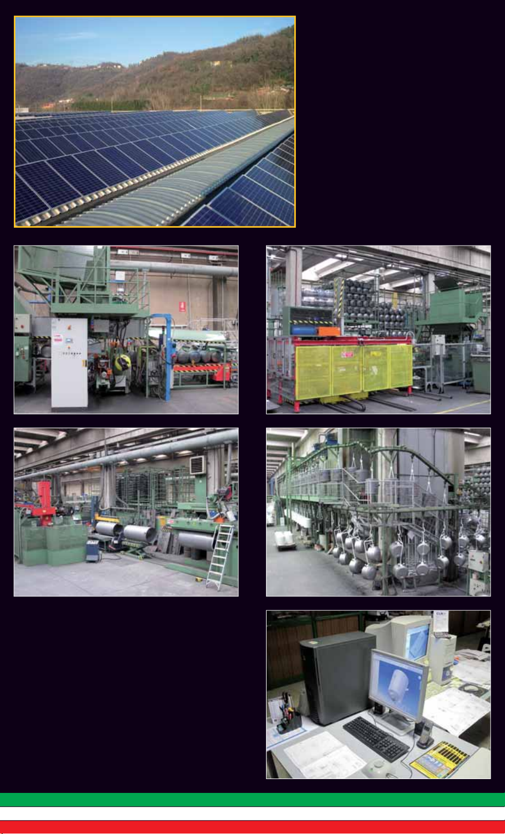
REALIZZAZIONE IMPIANTO
FOTOVOLTAICO
L’azienda Boschetti guarda al futuro con innovazioni
tecnologiche legate ad una filosofia il cui principio
ispiratore è il rispetto per l’ambiente e l’uso
razionale dell’energia.
Presso il nostro stabilimento è stato realizzato un
moderno impianto fotovoltaico di 200 kW che
consente di produrre un’importante risorsa di
energia pulita da fonti rinnovabili.
REALIZATION PHOTOVOLTAIC
SYSTEM
Boschetti Company looks at the future with technological innovations joined a philosophy whose
inspiring principle is the respect for the environment
together with the energy rational use.
By our factory has been realizated a modern
photovoltaic system of 200 kW which allows to
produce a relevant resource of clean energy from
renewable sources.
DESIGN, TECNOLOGIA E
PRODUZIONE ITALIANA
Crediamo nel MADE IN ITALY perchè la scelta di
materiali, lo sviluppo e la creatività di nuovi progetti
e tecnologie produttive, manodopera e servizi
nazionali permette di salvaguardare la qualità del
prodotto ed il benessere di tutta la filieria produttiva.
DESIGN, TECHNOLOGY AND
ITALIAN PRODUCTION
We believe in MADE IN ITALY because the selection of
materials, the development and the creativity of new
projects and production technology, labour force and
national services allows to safeguard the product
quality and the wellness of the complete production
chain.
Page 4
P
O
M
P
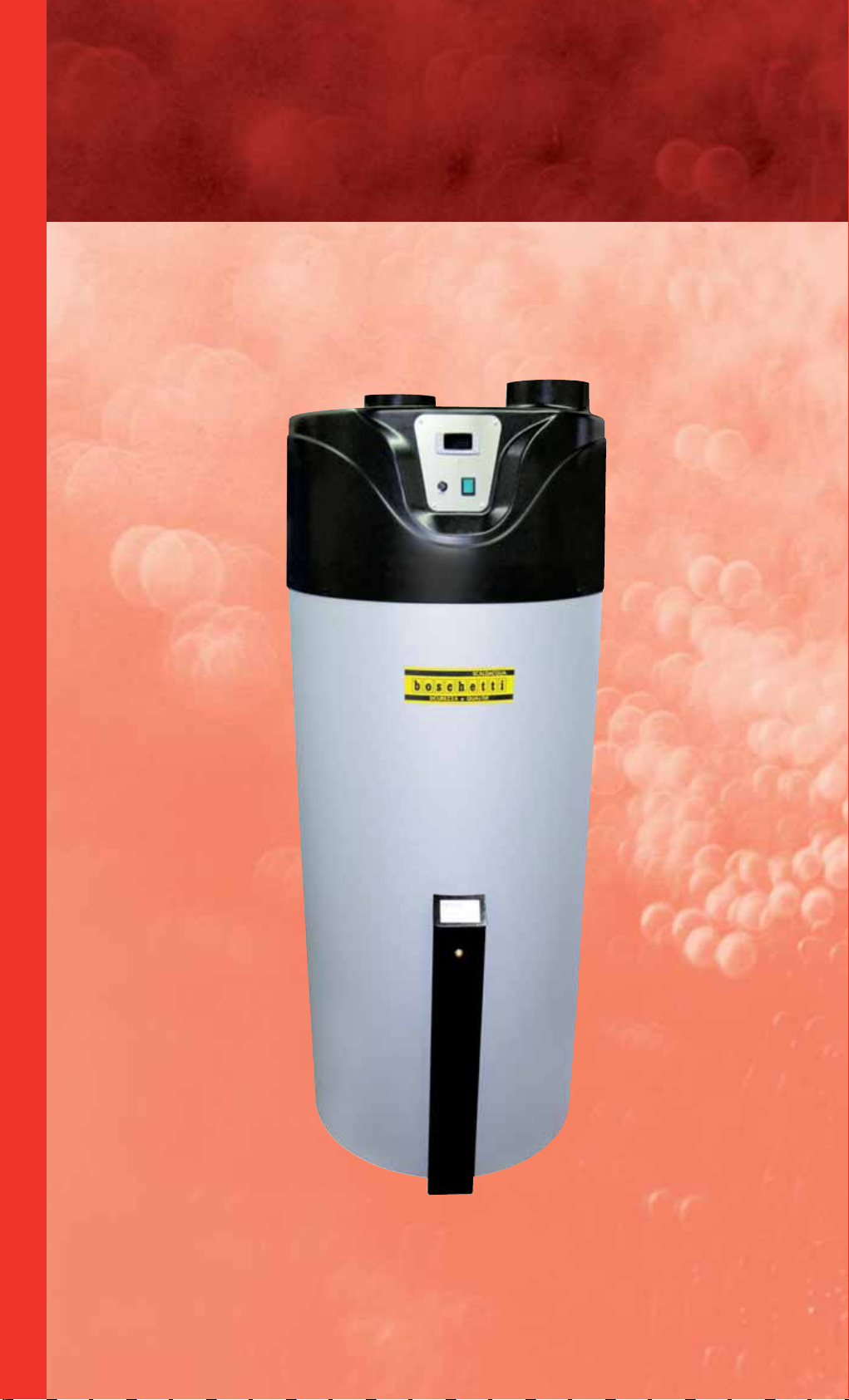
Pompa di calore
H
EAT PUMP
Modelli/Models COMFORT • COMFORT PLUS
A
D
I
C
A
L
O
R
E
Page 5
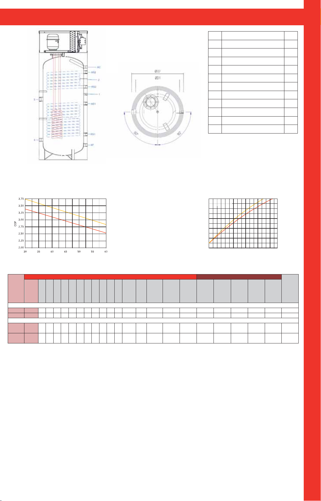
CARATTERISTICHE DELLA POMPA DI CALORE - CHARACTERISTICS OF HEAT PUMP
SE RP EN TIN I S OLA RI / S OLA R C OIL
g
SE RB AT OIO / T AN K
(
)
(
)
Ricircolo
1
Recirculation
Pozzetto per sonda
2
Sleeve for thermal probe
Anodo al magnesio
3
Magnesium anode
Manicotto per resistenza
4
Sleeve for resistance
Mandata scambiatore fisso inferiore
AS1
Discharge fixed enchanger lower
Ritorno scambiatore fisso inferiore
RS1
Return fixed enchanger lower
Mandata scambiatore fisso superiore
AS2
Dischar
e fixed enchanger higher
Ritorno scambiatore fisso superiore
RS2
Return fixed enchanger higher
Acqua fredda
AF
Cold water
Acqua calda
AC
Hot water
Diametro senza isolamento
D1
Diameter without insulation
Acqua calda
D2
Diameter with insulation
Air 15° C
Air 20° C
Middle C.O.P. with ambient temperature of 15°C and of 20°C
C.O.P. medio con temperatura d’ambiente
di 15°C e di 20°C
Air 15° C
Air 20° C
Temperatura bollitore (C°)
Boiler temperature (°C)
Starting temperature of the boiler 15°C
Ambient temperature 15°C and 20°C
Temperatura iniziale del bollitore 15°C
Temperatura ambiente 15°C e 20°C
60
55
50
45
40
35
30
25
20
Boiler temper ature (°C)
Temperatura bollitore (C°)
15
10
00:0 01:12 02:24 03:36 04:48 06:00 07:12 08:24 09:36
Tempi di riscaldamento riferiti a 300 lt
Heating times referred to 300 lt
½”
Ø22
1”½
1”¼
1”
1”
1”
1”
1”
1”
P
O
M
P
A
D
I
Modello
Capacità
Model
Capacity
12 3 4 AF AC RS1 AS1 RS2 AS2 Ø D1
(Lt)
Comfort 200
Comfort 300
Comfort
Plus 200
Comfort
Plus 300
Comfort = Boschetti Pompa di Calore Comfort
200
714 964 615 264 194 1154 330 555 500 650 1650 1770 60°C 6 0,65 4,5 10 125
300
890 1090 820 270 200 1260 345 765 550 650 1760 1870 60°C 6 1,31 8,6 10 153
200 714 964 615 264 194
300 890 1090 820 270 200
1 SCAMBIATORE
1154 330 555 884 1084 500 650 1650 1770 60°C 6 0,65 4,5 0,65 4,5 10 135
1260 345 765 990 1190 550 650 1760 1870 60°C 6 1,31 8,6 0,65 4,5 10 169
S
VERSIONE COMFORT / COMFORT VERSION 1 SCAMBIATORE / COIL
VERSIONE COMFORT PLUS / COMFORT PLUS VERSION 2 SCAMBIATORI / COIL
Comfort Plus = Boschetti Pompa di Calore Comfort Plus
Ø D2
con
isolamento
with
insulation
2 SCAMBIATORI
H
Altezza
Height
Ribaltamento
Capsizing
La pompa di calore installata internamente è stata concepita per sfruttare
l’energia termica presente nell’aria come fonte di riscaldamento per acqua
ad uso sanitario.
Il bollitore produce in modo efficiente acqua calda sanitaria utilizzando la
consolidata tecnologia delle pompe di calore.
La facilita’ d’installazione, il funzionamento silenzioso ed affidabile e la mo-
derata esigenza di manutenzione completano i vantaggi di questo sistema
altamente ecologico ed economico.
Il principio di funzionamento
Il fluido frigorifero cambia lo stato nell’evaporatore prelevando calore dall’aria esterna del locale.
Il compressore aumenta il livello energetico del calore prelevato aumentando di pressione e raggiungendo temperature vicine ai 90°C.
Nel condensatore diventa possibile trasferire energia termica all’acqua sanitaria riscaldandola fino a 60°C.
Passando nella valvola d’espansione posta alla fine del circuito, il fluido torna a bassa pressione, si raffredda ed è nuovamente disponibile per ricomin-
ciare il ciclo di produzione di energia dall’aria.
Temperatura
massima di
esercizio
Maximum
working
temperature
Pressione
massima di
esercizio
Maximum
working
pressure
S
Serpentino
Serpentino
Coil under
bar
sotto
(mq)
sotto
contenuto
Coil under
capacity
(Lt)
Serpentino
sopra
Coil over
(mq)
Serpentino
sopra
contenuto
Coil over
capacity
Pressione
massima di
Peso a vuoto
esercizio
Maximum
working
pressure
(Lt)
Empty
weight
bar
The heat pump internally installated, was designed to exploit the thermic energy present in the air and as heating source for sanitary water.
The boiler produces efficiently sanitary hot water, using the consolidated
technology of heat pumps.
The easy installation, the silent operation and the reliable and moderated
need of maintenance complete the advantages of this highly economic and
ecological system.
Operating principle
The refrigerant fluid changes of state evaporating, taking heat from the air
outside of the room.
The compressor increases the energetic level of the drawed heat, increasing
pressure and reaching temperature near to 90°C.
In the condenser becomes possible to transfer thermic energy from sanitary
water, heating it till 60°C.
Passing the sanitary water in the expansion valve placed at the end of the
circuit, the fluid returns at low pressure, becomes cooler and it is possible
to start again the energy production cycle from air.
C
A
L
O
R
E
Quote e illustrazioni sono indicative. Il costruttore si riserva la facoltà di apportare eventuali modifiche senza alcun preavviso.
Dimensions and pictures are only indicatives. The manufacturer has the
right to make changes without notice.
3
Page 6
IPX4
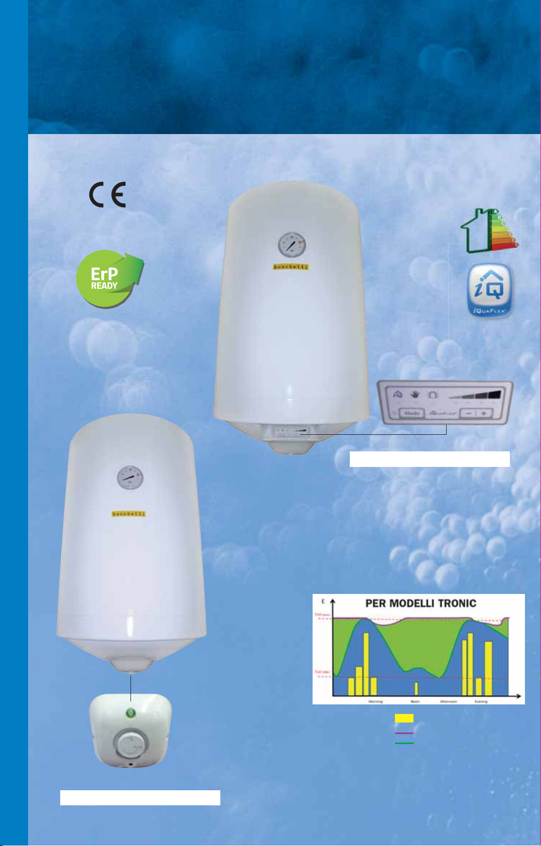
Scaldacqua elettrici verticali a parete
a risparmio energetico.
V
ERTICAL ELECTRIC WALL WATER HEATERS
S
C
A
L
D
A
C
Q
U
WITH ENERGY SAVING
.
Modelli/Models BSEGOLD • BSETRONIC • BSETGOLD
TRONIC
A
E
L
E
T
T
R
I
C
I
GOLD
Controllo elettronico regolabile esterno
con tecnologia risparmio energia
DIAGRAMMA DI UTILIZZO IPOTETICO GIORNALIERO
CONFRONTO CONSUMI TRA SCALDACQUA TRADIZIONALI
CON BSETRONIC
Termostato regolabile esterno
con tecnologia risparmio energia
Tset Max. = 65°C Prelievo d’acqua
Tset Min. = 45°C
Consumo scaldacqua tradizionale
Consumo BSETRONIC
Page 7
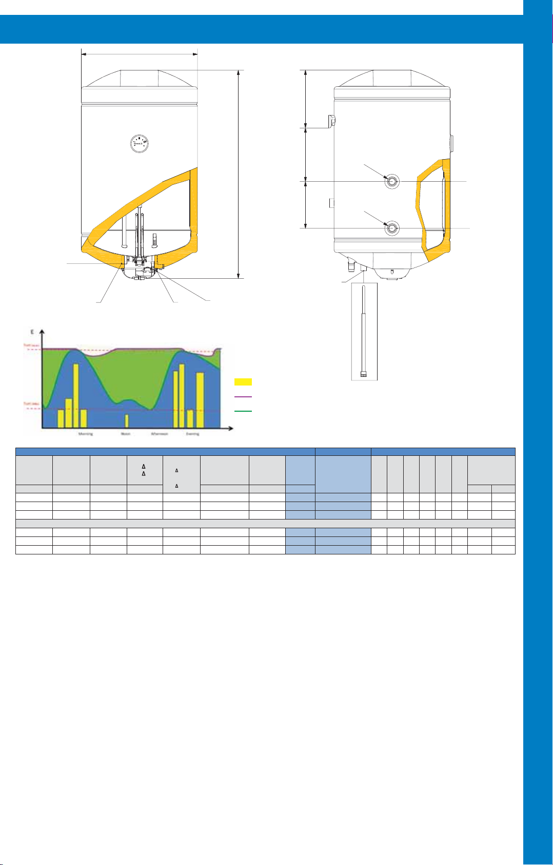
CARATTERISTICHE DEGLI SCALDACQUA - CHARACTERISTICS OF WATER HEATERS
CA RA TT ERI STI CHE / CHA RA CT ERI STI CS
DI MEN SI ON I / D IM EN SIO NS
MO DEL LO/O /
MO DEL
D
h1
H
Uscita H2O
Hot water exit
Manicotto ½" per sonda termica
Sleeve ½" for thermic probe
Entrata H
Ø1
CONFRONTO CONSUMI TRA SCALDACQUA TRADIZIONALE
Potenza Termica
Thermal Power
Watts Volts *** Lt ** Lt/h kW kg Lt
1200 ~220-230 112 23
1200 ~220-230 160 23
1200 ~220-230 200 23
1200 ~220-230 112 23
1200 ~220-230 160 23
1200 ~220-230 200 23
* Fluido riscald ante 80°C.
** Temperatura in entrata 15°C.
*** Termostato a 70°C. Temperatura ingresso 15°C.
BSEGOLD = Boschetti Scaldacqua Elettrico serie Gold
BSETGOLD = Boschetti Scaldacqua Elettrico Termo serie Gold
Tensione
Voltage
CON BSETRONIC
C
Unico Prelievo
Single Drawing
40°C
Resa
Yield
T 45°C
T 45°C
Ø1
DIAGRAMMA DI UTILIZZO IPOTETICO GIORNALIERO
Scambiatore
termo*
Resa
Heat Exchanger*
Yield T 45°C-lt/h
T 45°C-lt/h
Consumption in 24h to
maintain temperature
VERSIONE TERMO BILATERALE / BILATERAL THERMO VERSION
85
85
85
BSETRONIC = Boschetti Scaldacqua Elettrico serie Tronic
Lo scaldacqua è stato realizzato per durare e per soddisfare in modo affidabile e conveniente le esigenze familiari di acqua calda.
1) Il serbatoio in lamiera di grosso spessore è collaudato a 12 bar e garantito per pressioni di esercizio di 8 bar. L’attenta esecuzione dei semilavorati e l’esclusiva tecnica di assemblaggio garantiscono una perfetta applicazione delle resine protettive (polimerizzate ad alta temperatura), dando qualità al prodotto finito.
2) Nella versione termo, lo scambiatore di ampia superficie, è ad intercapedine con gli attacchi bilaterali.
2O
Cold water entry
Tset Max. = 65°C
Tset Min. = 45°C
Prelievo d’acqua
Consumo scaldacqua tradizionale
Consumo BSETRONIC
Consumo in 24h per
mantenimento
temperatura
0,77 22 56 460 625 255 120
1,1 25 80 460 825 230 120
1,37 28 100 460 985 280 120
0,85 26 56 460 625 205 185 35 120
1,21 29 80 460 825 230 185 212 120
1,51 32 100 460 985 280 185 322 120
Peso
Weight
Capacità
Capacity
** Entry water temperature 15°C.
*** Thermostat 70°C. Entry water temperature 15°C.
The vertical electric wall water heater has been designed to last for a long
time to satisfy hot water’s family needs.
1) The tank is made in steel plate with a large thickness and tested to 12
bar for working pressure of 8 bar. The careful execution of the unfinished
products and the exclusive assembling technique allow a perfect application
of protecting resins (polymerized at high temperature), grant quality to the
finished products.
2) In thermo version, the heat exchanger with a big surface, has hollow
space and bilateral thermo connections.
h3
h2
MODELL
Modello
Model
GOLD
TRONIC
BSE 50
BSE 80
BSE 100
BSET 50
BSET 80
BSET 100
* Heated fluid 80°C.
MODEL
Ø
2
Ø2
La guaina per la sonda termica non è a corredo
con lo scaldacqua.
La lunghezza deve essere di 270 mm
(vedi disegno a lato).
The smeath for thermic probe isn't supplied
togheter with the water heater.
Lenght have to be 270mm (see drawing by side).
D
D
mm H mm
h1
mm
h2
mm
h3
mm imm
Mandata Termo
Therm Discharge
Ritorno Termo
Therm Return
Attacchi
Connections
Ø1 Ø2
½
½
½
½”
¾”
½”
¾”
½”
¾”
S
C
A
L
D
A
C
Q
U
A
E
L
E
T
T
R
I
C
I
3) La coibentazione è composta da schiuma di poliuretano espanso senza
cloro-fluorocarburi (CFC free), idro-fluorocarburi (HFC free), e idro-cloro-fluorocarburi (HCFC free) gas responsabili della rarefazione della fascia d’ozono e
corresponsabili del cosiddetto effetto serra.
4) L’esterno in lamiera, curato nell’estetica e nella lavorazione, è ricoperto
da resine bianche applicate e cotte a forno a 220°C dopo un adeguato pretrattamento.
Quote e illustrazioni sono indicative. Il costruttore si riserva la facoltà di
apportare eventuali modifiche senza alcun preavviso.
3) The insulation is made up of polyurethane foam CFC free, HFC free and
HCFC free. These gas are responsible for ozone’s rarefaction and for green-
house effect.
4) The external covering is made in steel plate coated with white resins applied and 220°C furnace cooked after adequate pre-treatment.
Dimensions and pictures are only indicatives. The manufacturer has the
right to make changes without notice.
5
Page 8
IPX4
S
C
A
L
D
A
C
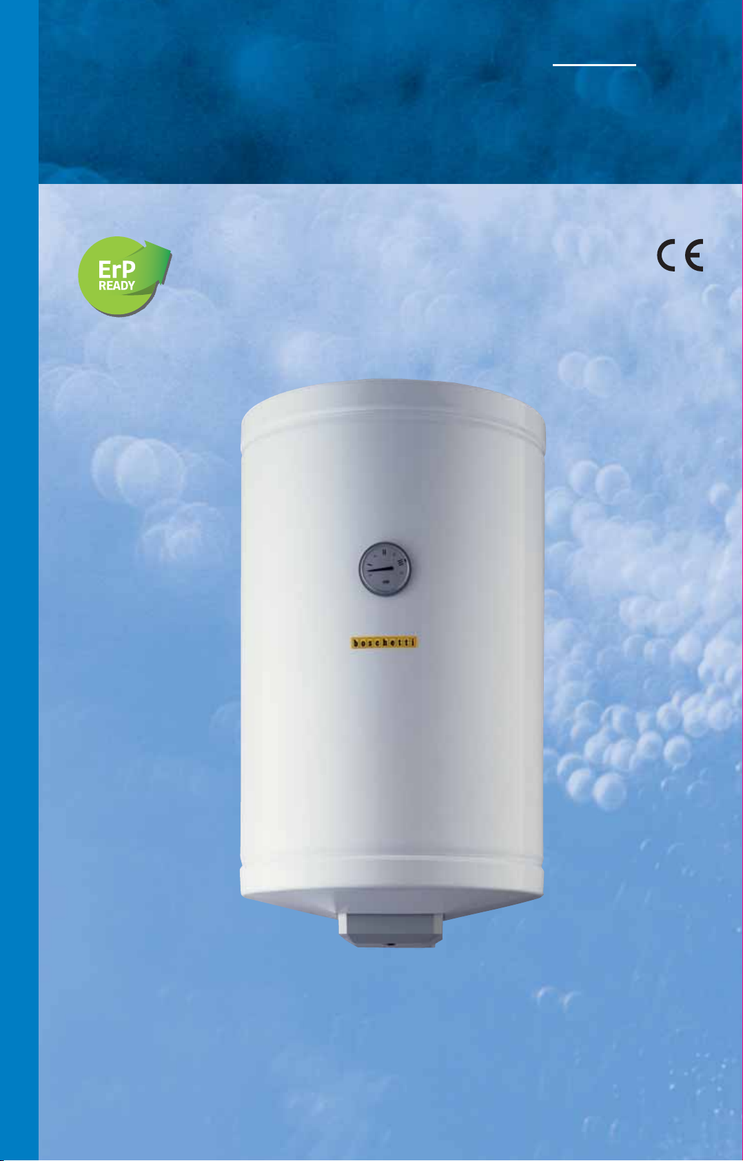
Scaldacqua elettrici verticali a parete.
V
ERTICAL ELECTRIC WALL WATER HEATERS.
Modelli/Models BSE • BSET
Q
U
A
E
L
E
T
T
R
I
C
I
Page 9
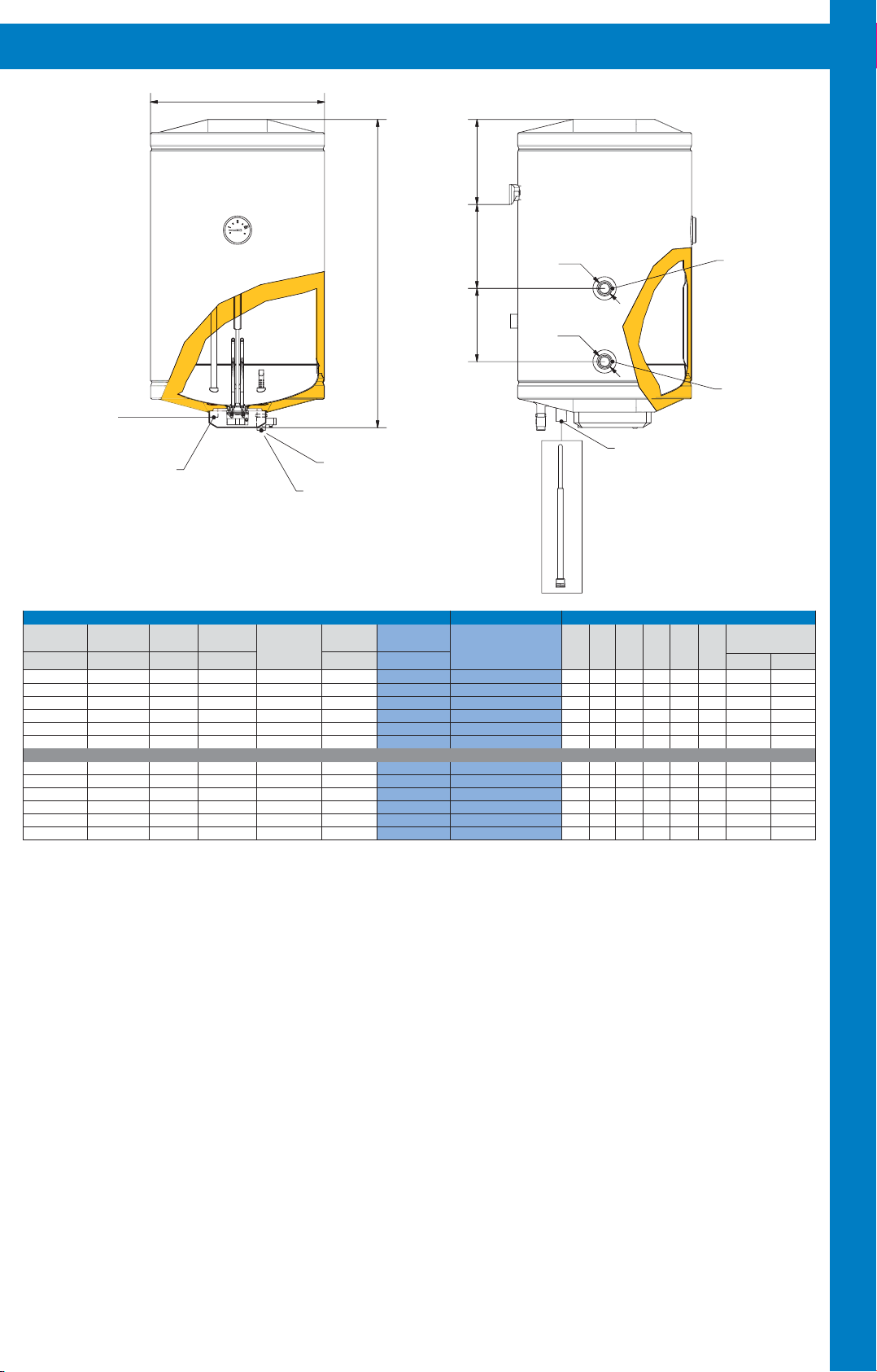
CARATTERISTICHE DEGLI SCALDACQUA - CHARACTERISTICS OF WATER HEATERS
D
1
h
3
h
H
Ø2
Manda ta Ter mo
Therm Discharge
Uscit a H2O
Hot water exit
Per Mod. 50-80-100-120 Ø1
For models 50-80-100-120 Ø1
Per Mod. 150-200 Ø2
For models 150-200 Ø2
Potenza Termica
Thermal Power
Watts
1200
1200
1200
1200
1500
2000
1200
1200
1200
1200
1500
2000
*Fluido riscaldante 80°C.
** Temperatura in entrata 15°C.
*** Termostato a 70°C. Temperatura ingresso 15°C.
Tensione
Voltage
Volts
~ 220-230
~ 220-230
~ 220-230
~ 220-230
~ 220-230
~ 220-230
~ 220-230
~ 220-230
~ 220-230
~ 220-230
~ 220-230
~ 220-230
CARATTERISTICHE/CHARACTERISTICS MODELLO/MODEL DIMENSIONI/DIMENSIONS
Unico Prelievo
Resa ΔT45°C
Single Drawing
Yield ΔT45°C
40°C
**Lt/h***Lt
112
160
200
240
300
400
112
160
200
240
300
400
23
23
23
23
29
38
23
23
23
23
29
38
2
h
Entrata H 2O
Cold water entry
Ø1
Scambiatore termo*
Resa ΔT 45°C-lt/h
Heat Exchanger*
Yield ΔT 45°C-lt/h
VERSIONE TERMO BILATERALE/BILATERAL THERMO VERSION
85
85
85
85
204
204
Peso
Weight
20
24
27
32
43
56
24
28
31
36
53
66
Capacità
Capacity
Lt.Kg
56
80
100
120
150
200
56
80
100
120
150
200
*Heated fluid 80°C.
** Entry water temperature 15°C.
***Thermostat 70°C. Entry water temperature 15°C.
Modello
Model
BSE 50
BSE 80
BSE 100
BSE 120
BSE 150
BSE 200
BSET 50
BSET 80
BSET 100
BSET 120
BSET 150
BSET 200
Ø2
Mani cot to ½" per sond a term ica
Sleeve ½" for thermic probe
La guaina per la sonda termica non è a corredo
con lo scaldacqua.
La lunghezza deve esser e di 270 mm (vedi
disegno a lato).
The smeath for thermic probe isn't supplied
togheter with the water heat er.
Lenght have to be 270mm (see drawing by side).
1
2
DmmHmmh
580
440
780
440
940
440
1110
440
1100
490
1430
490
580
440
780
440
940
440
1110
440
1100
490
1430
490
mm
235
215
265
255
250
400
190
215
265
255
250
400
h
mm
185
185
185
185
520
520
h
mm
35
212
322
492
137
305
3
mm
120
120
120
120
140
140
120
120
120
120
140
140
Ritorno Termo
Therm Return
i
Ø1
1/2”
1/2”
1/2”
1/2”
1/2”
1/2”
1/2”
1/2”
1/2”
1/2”
1/2”
1/2”
Attacchi
Connections
Ø2
3/4”
3/4”
3/4”
3/4”
3/4”
3/4”
3/4”
3/4”
S
C
A
L
D
A
C
Q
U
A
E
L
E
T
T
BSE = Boschetti Scaldacqua Elettrico
BSET = Boschetti Scaldacqua Elettrico Termo
Lo scaldacqua è stato realizzato per durare e per soddisfare in modo affidabile e conveniente le esigenze familiari di acqua calda.
1) Il serbatoio in lamiera di grosso spessore è collaudato a 12 bar e garantito per pressioni di esercizio di 8 bar. L’attenta esecuzione dei semilavorati e l’esclusiva tecnica di assemblaggio garantiscono una perfetta applicazione delle resine protettive (polimerizzate ad alta temperatura), dando qualità al prodotto finito.
2) Nella versione termo, lo scambiatore di ampia superficie, è ad intercapedine con gli attacchi bilaterali.
3) La coibentazione è composta da schiuma di poliuretano espanso senza
cloro-fluorocarburi (CFC free), idro-fluorocarburi (HFC free), e idro-cloro-fluorocarburi (HCFC free) gas responsabili della rarefazione della fascia d’ozono e
The vertical electric wall water heater has been designed to last for a long
time to satisfy hot water’s family needs.
1) The tank is made in steel plate with a large thickness and tested to 12
bar for working pressure of 8 bar. The careful execution of the unfinished
products and the exclusive assembling technique allow a perfect application
of protecting resins (polymerized at high temperature), grant quality to the
finished products.
2) In thermo version, the heat exchanger with a big surface, has hollow
space and bilateral thermo connections.
3) The insulation is made up of polyurethane foam CFC free, HFC free and
HCFC free. These gas are responsible for ozone’s rarefaction and for green-
house effect.
corresponsabili del cosiddetto effetto serra.
4) L’esterno in lamiera, curato nell’estetica e nella lavorazione, è ricoperto
da resine bianche applicate e cotte a forno a 220°C dopo un adeguato pre-
4) The external covering is made in steel plate coated with white resins applied and 220°C furnace cooked after adequate pre-treatment.
trattamento.
Quote e illustrazioni sono indicative. Il costruttore si riserva la facoltà di
apportare eventuali modifiche senza alcun preavviso.
Dimensions and pictures are only indicatives. The manufacturer has the
right to make changes without notice.
R
I
C
I
7
Page 10
S
C
A
L
D
A
C
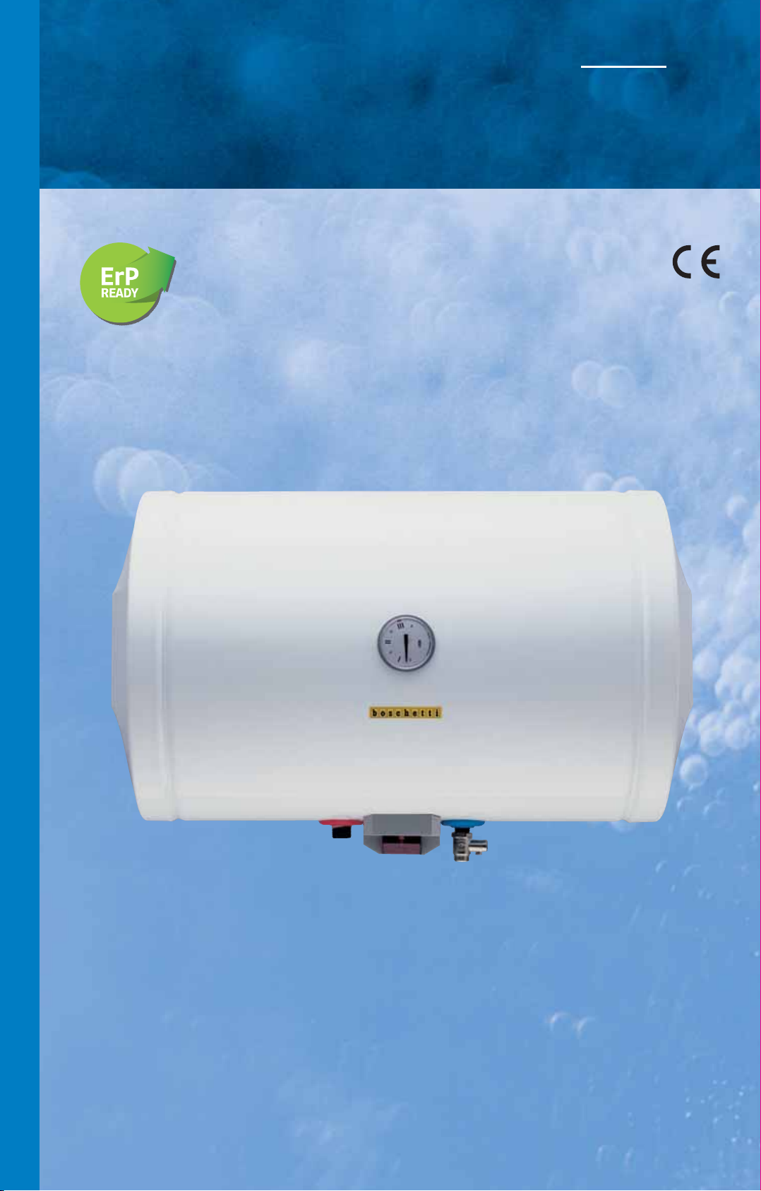
Scaldacqua elettrici orizzontali a parete.
H
ORIZONTAL ELECTRIC WALL WATER HEATERS.
Modelli/Models OBSE • OBSET
Q
U
A
E
L
E
T
T
R
I
C
I
Page 11
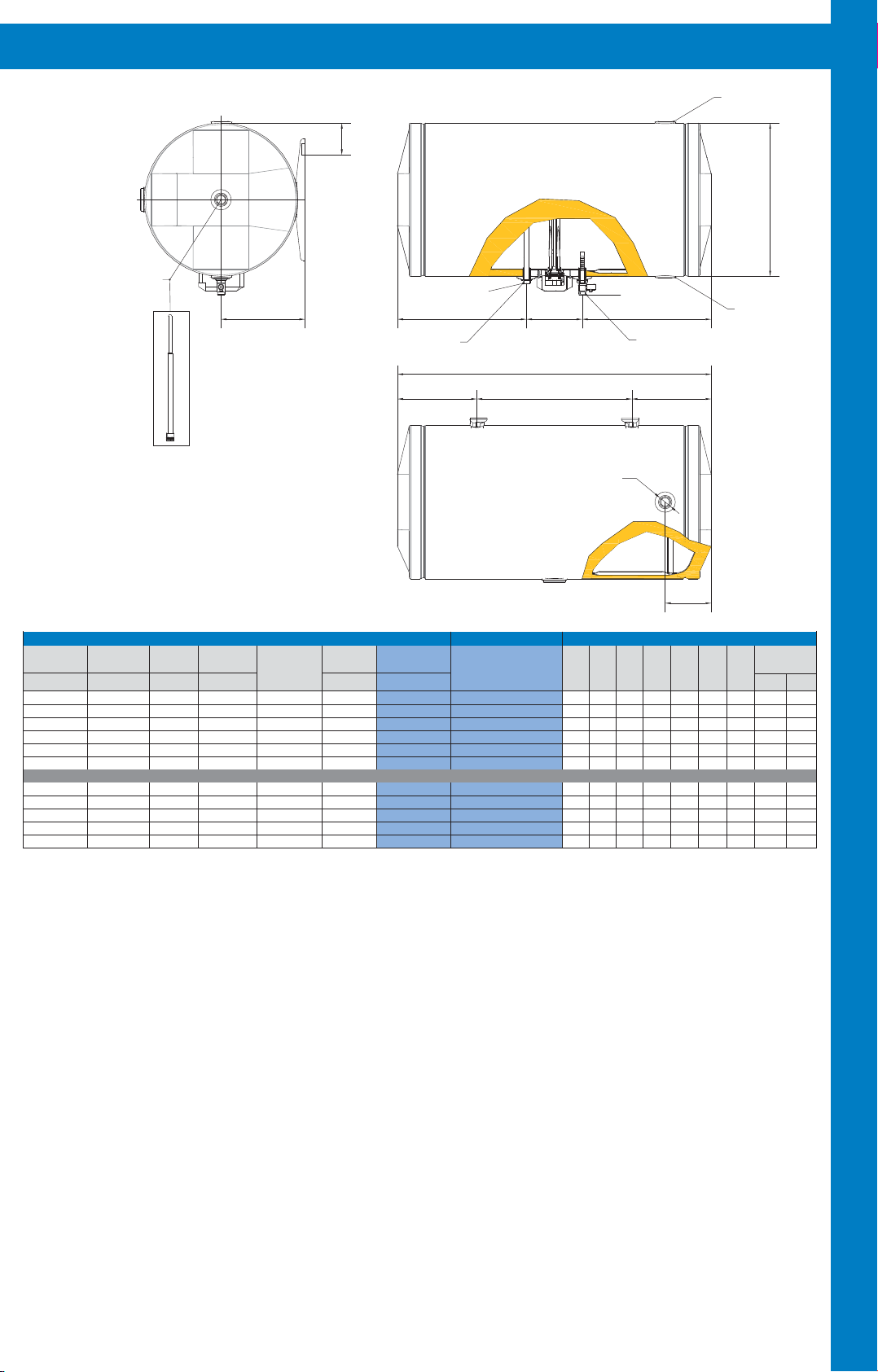
CARATTERISTICHE DEGLI SCALDACQUA - CHARACTERISTICS OF WATER HEATERS
Mandata Termo
Thermo water entry
2
d
D
Manicotto ½" per sonda termica
Sleeve ½" for thermic probe
1
d
La guaina per la sonda termica non è a corredo
con lo scaldacqua.
La lunghezza deve ess ere di 270 mm
(vedi disegno a lato).
The smeath for thermic probe isn't supplied
togheter with the water heater.
Lenght have to be 270mm (see drawing by side).
Mod. 50-80-100-120 Ø1
Mod. 150-200 Ø2
Uscita H2O
Hot water exit
= =
= =
i
L
1
L
Entrata H2O
Cold wa ter e ntry
Ø1
Ritorno Termo
Thermo water exit
S
C
A
L
CARATTERISTICHE/CHARACTERISTICS MODELLO/MODEL DIMENSIONI/DIMENSIONS
Potenza Termica
Thermal Power
Watts
1200
1200
1200
1200
1500
2000
1200
1200
1200
1500
2000
*Fluido riscaldante 80°C.
** Temperatura in entrata 15°C.
*** Termostato a 70°C. Temperatura ingresso 15°C.
OBSE = Orizzontale Boschetti Scaldacqua Elettrico
OBSET = Orizzontale Boschetti Scaldacqua Elettrico Termo
Tensione
~ 220-230
~ 220-230
~ 220-230
~ 220-230
~ 220-230
~ 220-230
~ 220-230
~ 220-230
~ 220-230
~ 220-230
~ 220-230
Voltage
Volts
Unico Prelievo
Single Drawing
40°C
90
128
160
192
240
320
100
120
144
180
240
Resa ΔT45°C
Yield ΔT45°C
**Lt/h***Lt
23
23
23
23
29
38
23
23
23
29
38
Scambiatore termo*
Resa ΔT 45°C-lt/h
Heat Exchanger*
Yield ΔT 45°C-lt/h
Peso
Weight
21
26
29
33
45
VERSIONE TERMO DESTRI/RIGHT THERMO VERSION
40
60
60
60
100
57
29
33
37
49
64
Capacità
Capacity
Lt.Kg
56
80
100
120
150
200
80
100
120
150
200
*Heated fluid 80°C.
** Entry water temperature 15°C.
***Thermostat 70°C. Entry water temperature 15°C.
Modello
Model
OBSE 50
OBSE 80
OBSE 100
OBSE 120
OBSE 150
OBSE 200
OBSET 80
OBSET 100
OBSET 120
OBSET 150
OBSET 200
DmmL
440
440
440
440
490
490
440
440
440
490
490
mm
540
740
900
1070
1055
1385
740
900
1070
1055
1385
Ø2
L
mm
160
325
445
620
620
620
325
445
620
620
620
D
A
C
Q
2
L
U
A
Ø2
E
L
E
T
mm
125
125
130
200
200
i
2
L
mm
160
160
160
160
160
160
160
160
160
160
160
d1
mm
240
240
240
240
270
270
240
240
240
270
270
1
mm
95
95
95
95
95
95
95
95
95
95
95
d
2
Attacchi
Connections
Ø1
1/2”
1/2”
1/2”
1/2”
1/2”
3/4”
1/2”
3/4”
1/2”
3/4”
1/2”
3/4”
1/2”
3/4”
1/2”
3/4”
1/2”
3/4”
T
R
Lo scaldacqua è stato realizzato per durare e per soddisfare in modo affidabile e conveniente le esigenze familiari di acqua calda.
1) Il serbatoio in lamiera di grosso spessore è collaudato a 12 bar e garantito per pressioni di esercizio di 8 bar. L’attenta esecuzione dei semilavorati e l’esclusiva tecnica di assemblaggio garantiscono una perfetta applicazione delle resine protettive (polimerizzate ad alta temperatura), dando qualità al prodotto finito.
2) Nella versione termo lo scambiatore ad intercapedine con gli attacchi de-
stri è di ampia superficie e garantisce un elevato scambio di calore.
3) La coibentazione è composta da schiuma di poliuretano espanso senza
cloro-fluorocarburi (CFC free), idro-fluorocarburi (HFC free), e idro-cloro-fluorocarburi (HCFC free) gas responsabili della rarefazione della fascia d’ozono e
The horizontal electric wall water heater has been designed to last for a long
time to satisfy hot water’s family needs.
1) The tank is made in steel plate with a large thickness and tested to 12
bar for working pressure of 8 bar. The careful execution of the unfinished
products and the exclusive assembling technique allow a perfect application
of protecting resins (polymerized at high temperature), grant quality to the
finished products.
2) In thermo version, the heat exchanger with a big surface and high thermal efficiency, has hollow space and right thermo connections.
3) The insulation is made up of polyurethane foam CFC free, HFC free and
HCFC free. These gas are responsible for ozone’s rarefaction and for green-
house effect.
corresponsabili del cosiddetto effetto serra.
4) L’esterno in lamiera, curato nell’estetica e nella lavorazione, è ricoperto
da resine bianche applicate e cotte a forno a 220°C dopo un adeguato pre-
4) The external covering is made in steel plate coated with white resins applied and 220°C furnace cooked after adequate pre-treatment.
trattamento.
Quote e illustrazioni sono indicative. Il costruttore si riserva la facoltà di
apportare eventuali modifiche senza alcun preavviso.
Dimensions and pictures are only indicatives. The manufacturer has the
right to make changes without notice.
I
C
I
9
Page 12
Capacità
10
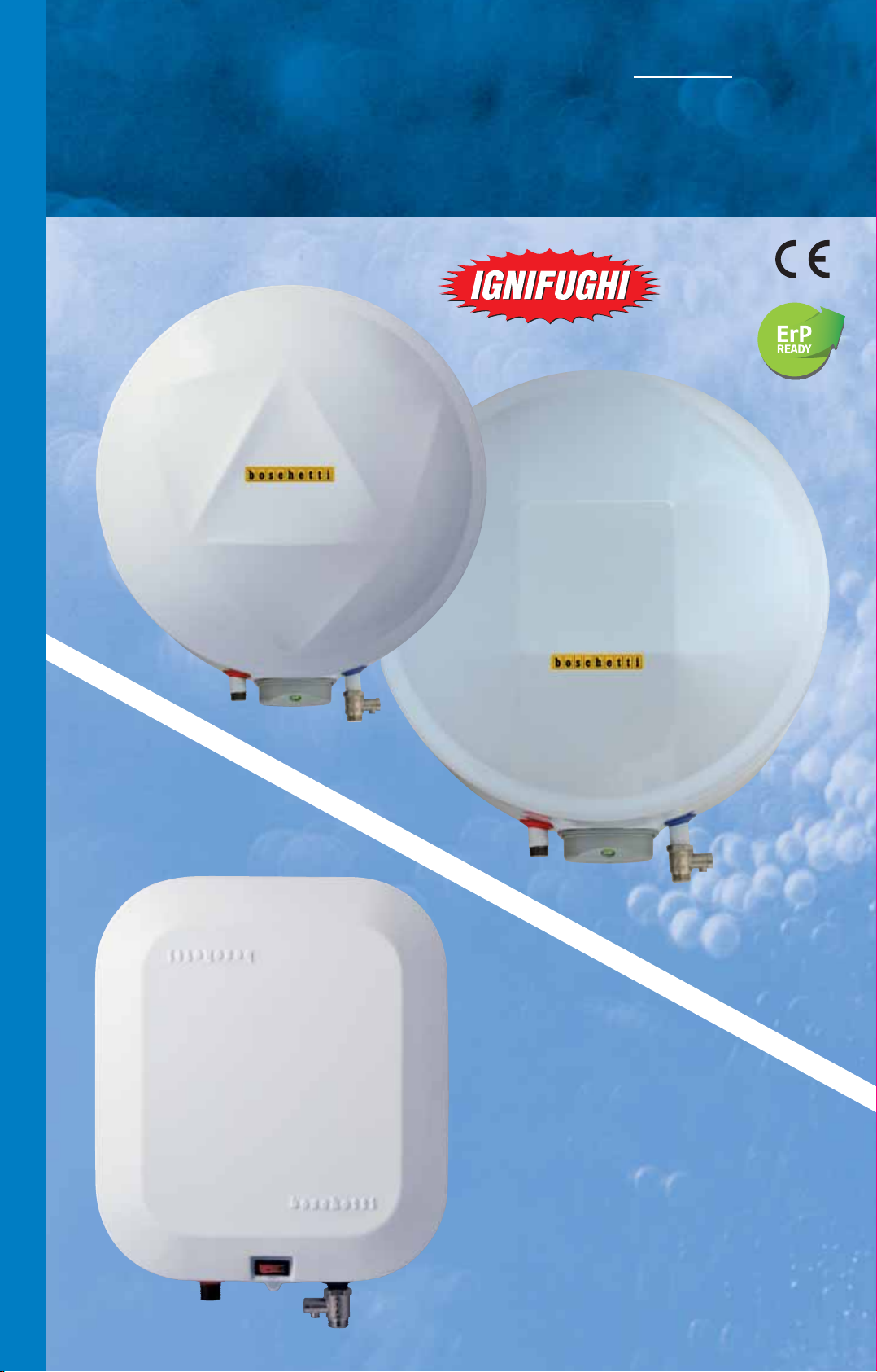
Scaldacqua elettrici rapidi a parete.
RAPID ELECTRIC WALL WATER HEATERS.
Modelli/Models BSER/Q • BSER/SQ
BSER/R • BSER/SR
S
C
A
L
D
A
C
Q
U
A
E
L
15
E
T
T
R
I
C
I
Capacità
10
Capacità
30
Page 13
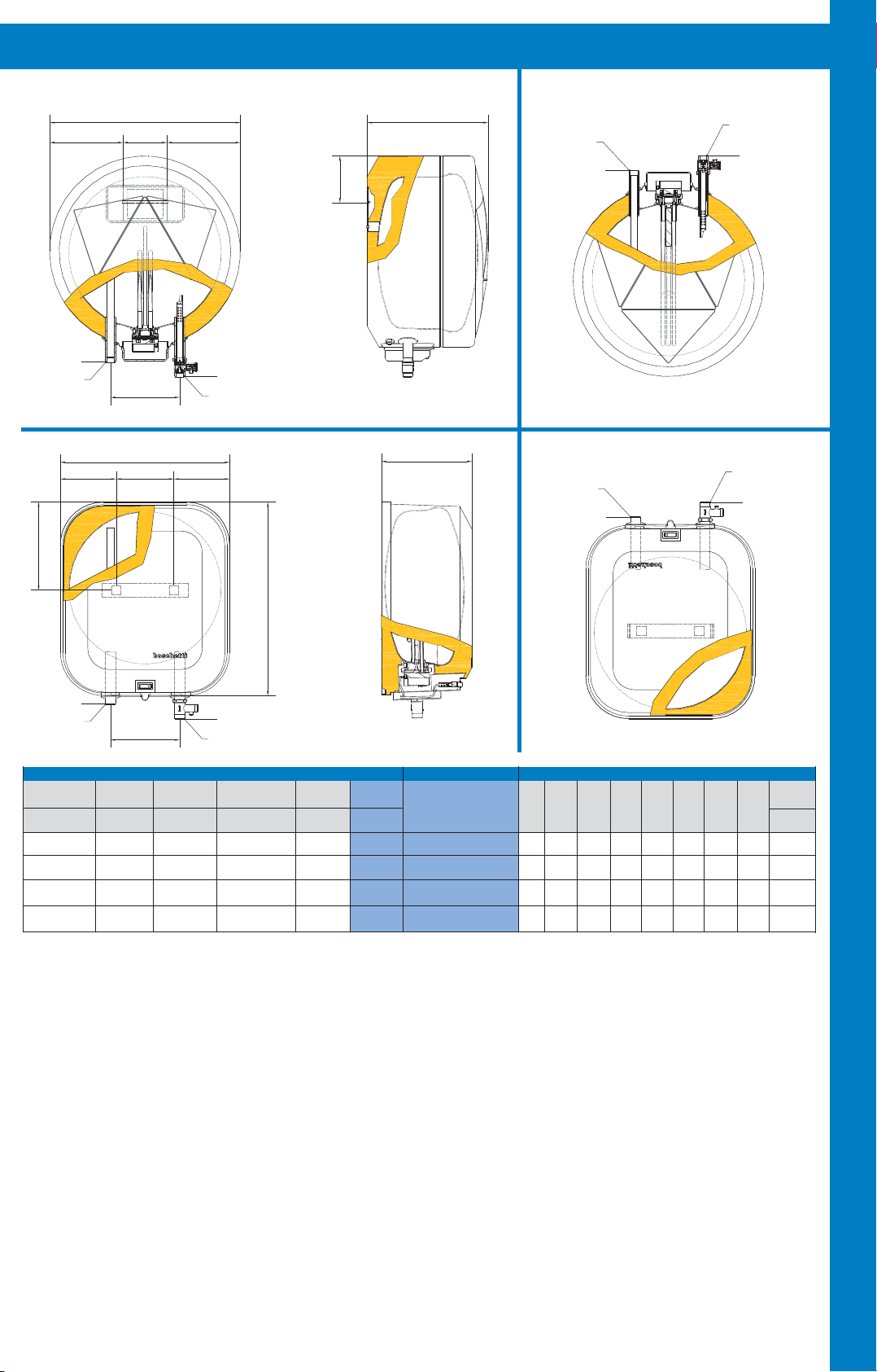
CARATTERISTICHE DEGLI SCALDACQUA - CHARACTERISTICS OF WATER HEATERS
= =
Ø1
Uscita H2O
Hot water exit
= =
1
d
VER SIONE SOPR ALAVE LLO
D
a
OVE R-S INK VE RS ION
1
d
Versione
Version
BSER/R 10
BSER/R 15
BSER/R 30
Fig.1
P
VER SIONE SOTTOLAVE LLO
UNDER -S INK VE R S ION
Uscita H2O
Hot water exit
Ø1
Entrata H2O
Cold water entry
Ø1
S
Ø1
i
Entrata H
2O
Cold water entry
Versione BSER/SR 10
Version BSER/SR 15
Fig.1
C
A
L
L
a
Versione
Version
BSER/Q 10
H
Fig.2
P
Uscita H2O
Hot water exit
Ø1
Entrata H
2O
Cold water entry
Ø1
D
A
C
Q
U
Ø1
Uscita H2O
Hot water exit
Potenza Termica
Thermal Power
Watts
1200
1500
1500
1200
** Temperatura in entrata 15°C.
*** Termostato a 70°C. Temperatura ingresso 15°C.
BSER/R = Boschetti Scaldacqua Elettrico Rapido Rotondo
BSER/Q = Boschetti Scaldacqua Elettrico Rapido
BSER/SQ = Boschetti Scaldacqua Elettrico Rapido Sottolavello
BSER/SR = Boschetti Scaldacqua Elettrico Rapido Sottolavello Rotondo
Lo scaldacqua, grazie anche alle ridotte dimensioni e ad un design apprezzato, costituisce una valida soluzione alle esigenze di acqua calda tipiche
della cucina, della toilette e della doccia.
1) Il serbatoio in lamiera di grosso spessore è collaudato a 12 bar e garantito per
pressioni di esercizio di 8 bar. L’attenta esecuzione dei semilavorati e l’esclusiva
tecnica di assemblaggio garantiscono una perfetta applicazione delle resine protettive (polimerizzate ad alta temperatura), dando qualità al prodotto finito.
2) La coibentazione è composta da schiuma di poliuretano espanso senza
cloro-fluorocarburi (CFC free), idro-fluorocarburi (HFC free), e idro-cloro-fluorocarburi (HCFC free) gas responsabili della rarefazione della fascia d’ozono e
corresponsabili del cosiddetto effetto serra.
3) L’esterno, curato nell’estetica e nella lavorazione, è in polistirolo termofor-
mato antiurto nei modelli da lt.10 versione: BSER/Q 10 - BSER/SQ 10, mentre in quelli da lt. 10-15 e 30 è in lamiera ricoperto da resine bianche applicate e cotte a forno a 220°C dopo un adeguato pretrattamento versione:
BSER/R 10 - BSER/SR 10 - BSER/R 15 - BSER/SR 15 - BSER/R 30.
i
CARATTERISTICHE/CHARACTERISTICS MODELLO/MODEL
Volts
Unico Prelievo
Single Drawing
***Lt
Tensione
Voltage
~220-230
~220-230
~220-230
~220-230
40°C
20
30
60
20
Ø1
Entrata H
2O
Cold water entry
Resa ΔT45°C
Yield ΔT45°C
**Lt/h
23
29
29
23
Peso
Weight
Kg.
7,5
8
10,5
6,5
Capacità
Capacity
Lt.
10
15
30
10
BSER/R 10 - BSER/SR 10
BSER/R 15 - BSER/SR 15
BSER/Q 10 - BSER/SQ 10
** Entry water temperature 15°C.
*** Thermostat 70°C. Entry water temperature 15°C.
The rapid electric wall water heater has small dimensions and appreciable
design; it’s a good solution for hot water’s needs in the kitchen, in the bath-
room and for shower.
1) The tank is made in steel plate with a large thickness and tested to 12
bar for working pressure of 8 bar. The careful execution of the unfinished
products and the exclusive assembling technique allow a perfect application
of protecting resins (polymerized at high temperature), grant quality to the
finished products.
2) The insulation is made up of polyurethane foam CFC free, HFC free and
HCFC free. These gas are responsible for ozone’s rarefaction and for green-
house effect.
3) The external covering in the 10 lt. models version: BSER/Q 10 - BSER/SQ 10
is made in thermoforming high-impact polystyrene. In the 10-15 and 30 lt.
models version: BSER/R 10 - BSERS/SR 10 - BSER/R 15 - BSER/SR 15 BSER/R 30 the external covering is made in steel plate coated with white
resins applied and 220°C furnace cooked after adequate pre-treatment.
Modello
Model
BSER/R 30
DIMENSIONI/DIMENSIONS
D
mm
400
400
460
H
mm
Fig.
1
1
1
2 405 355
Versione - Version
BSER/SQ 10
L
P
mm
mm
210
255
330
190
a
mm
90
90
90
120
d
mm
100
100
115
190
A
E
Fig.2
L
Attacchi
mm
145
145
145
145
i
Connections
Ø1
1/2”
1/2”
1/2”
1/2”
E
T
T
R
1
I
C
I
Quote e illustrazioni sono indicative. Il costruttore si riserva la facoltà di
apportare eventuali modifiche senza alcun preavviso.
Dimensions and pictures are only indicatives. The manufacturer has the
right to make changes without notice.
11
Page 14
S
C
A
L
D
A
C
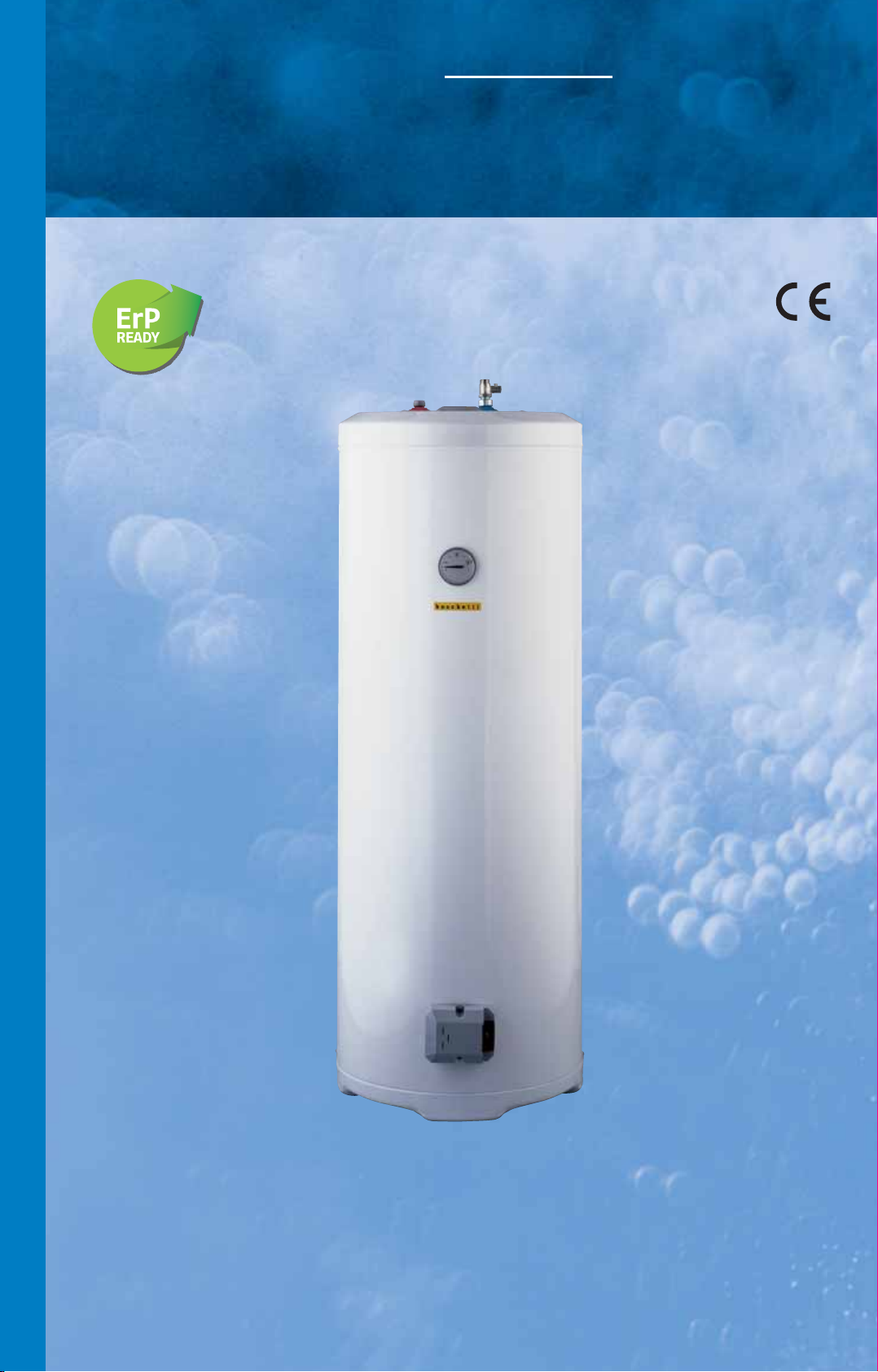
Scaldacqua elettrici con basamento uso domestico.
E
LECTRIC WATER HEATERS WITH BASE FOR DOMESTIC USE.
Modelli/Models BSEBD
Q
U
A
E
L
E
T
T
R
I
C
I
Page 15
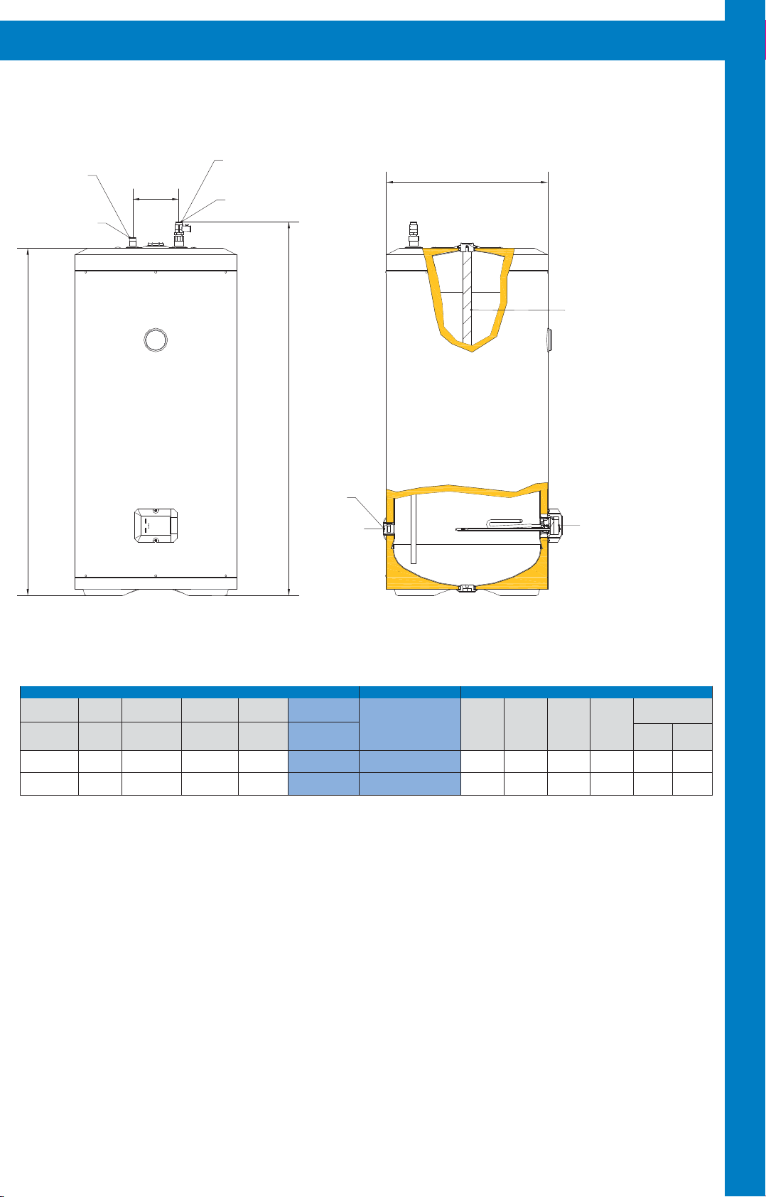
CARATTERISTICHE DEGLI SCALDACQUA - CHARACTERISTICS OF WATER HEATERS
Entrata H2O
Uscita H
Hot water exit
2
O
i
Ø2
Cold water entry
Ø2
D
Anodo in lega di magnesio AZ63
Magnesium anode AZ63
S
C
A
L
H
CARATTERISTICHE/CHARACTERISTICS MODELLO/MODEL DIMENSIONI/DIMENSIONS
Volts
Unico Prelievo
Single Drawing
40°C
***Lt
300
400
Resa ΔT45°C
ΔT
Yield
**Lt/h
29
38
Potenza termica
Thermal Power
Watts
1500
2000
** Temperatura in entrata 15 °C.
*** Termostato a 70 °C. Temperatura ingresso 15°C.
Tensione
Voltage
~220-230
~220-230
45°C
Peso
Weight
Kg
45
55
1
h
Ø1
Scarico
Water drain
Capacità
Capacity
Lt.
150
200
Modello
Model
BSEBD 150
BSEBD 200
** Entry water temperature 15 °C.
*** Thermostat 70°C. Entry water temperature 15°C.
D
mm
490
490
H
mm
1050
1380
1
h
mm
1140
1460
Gruppo RT
Resistance-Thermostat Unit
Attacchi
Connections
i
mm
Ø1
Ø2
140
3/4”
1/2”
140
3/4”
1/2”
D
A
C
Q
U
A
E
L
E
T
T
R
BSEBD = Boschetti Scaldacqua Elettrico Basamento Domestico
Lo scaldacqua è stato realizzato per durare e per soddisfare in modo affidabile e conveniente le esigenze familiari di acqua calda.
1) Il serbatoio in lamiera di grosso spessore è collaudato a 12 bar e garantito per pressioni di esercizio di 8 bar. L’attenta esecuzione dei semilavorati e l’esclusiva tecnica di assemblaggio garantiscono una perfetta applicazione delle resine protettive (polimerizzate ad alta temperatura), dando qualità al prodotto finito.
2) La coibentazione è composta da schiuma di poliuretano espanso senza
cloro-fluorocarburi (CFC free), idro-fluorocarburi (HFC free), e idro-cloro-fluorocarburi (HCFC free) gas responsabili della rarefazione della fascia d’ozono e
corresponsabili del cosiddetto effetto serra.
3) L’esterno in lamiera, curato nell’estetica e nella lavorazione, è ricoperto
da resine bianche applicate e cotte a forno a 220°C dopo un adeguato pretrattamento.
Quote e illustrazioni sono indicative. Il costruttore si riserva la facoltà di
apportare eventuali modifiche senza alcun preavviso.
The electric water heater with base for domestic use has been designed to
last for a long time to satisfy hot water’s family needs.
1) The tank is made in steel plate with a large thickness and tested to 12
bar for working pressure of 8 bar. The careful execution of the unfinished
products and the exclusive assembling technique allow a perfect application
of protecting resins (polymerized at high temperature), grant quality to the
finished products.
2) The insulation is made up of polyurethane foam CFC free, HFC free and
HCFC free. These gas are responsible for ozone’s rarefaction and for green-
house effect.
3) The external covering is made in steel plate coated with white resins applied and 220°C furnace cooked after adequate pre-treatment.
Dimensions and pictures are only indicatives. The manufacturer has the
right to make changes without notice.
I
C
I
13
Page 16
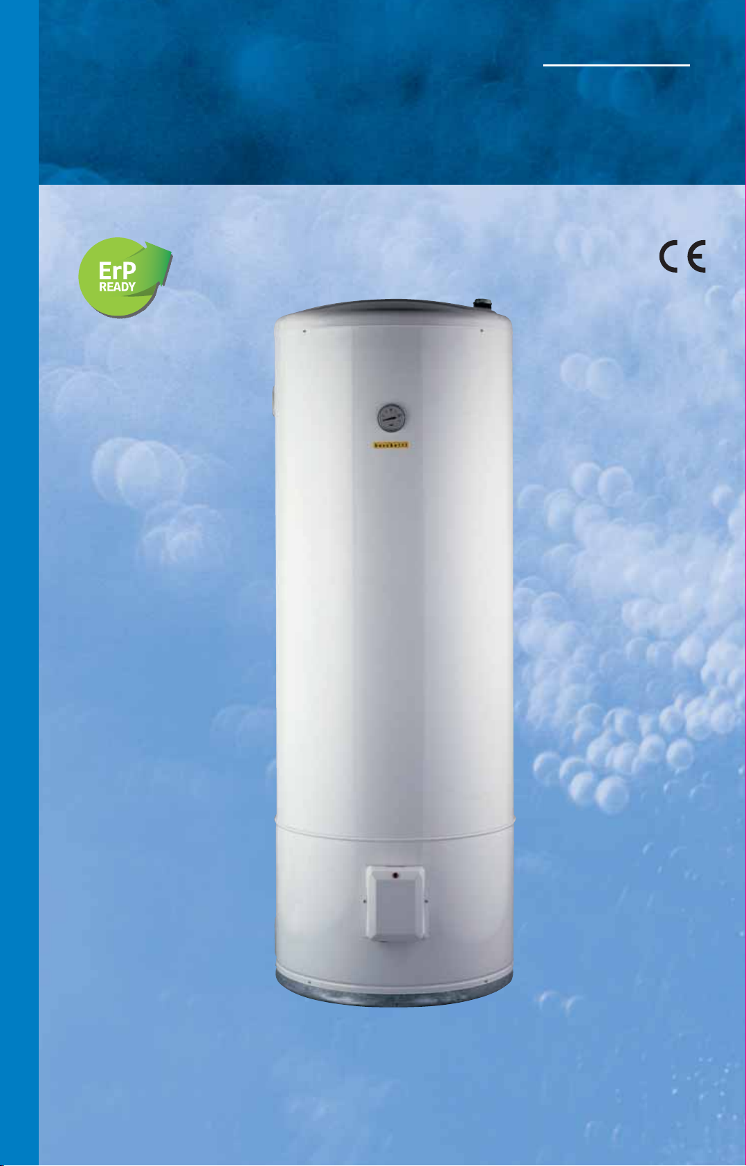
Scaldacqua elettrici verticali con basamento
uso commerciale.
S
C
A
L
D
A
C
Q
VERTICAL ELECTRIC WATER HEATERS WITH BASE FOR COMMERCIAL USE
Modelli/Models BSEBC • BSETBC
.
U
A
E
L
E
T
T
R
I
C
I
Page 17
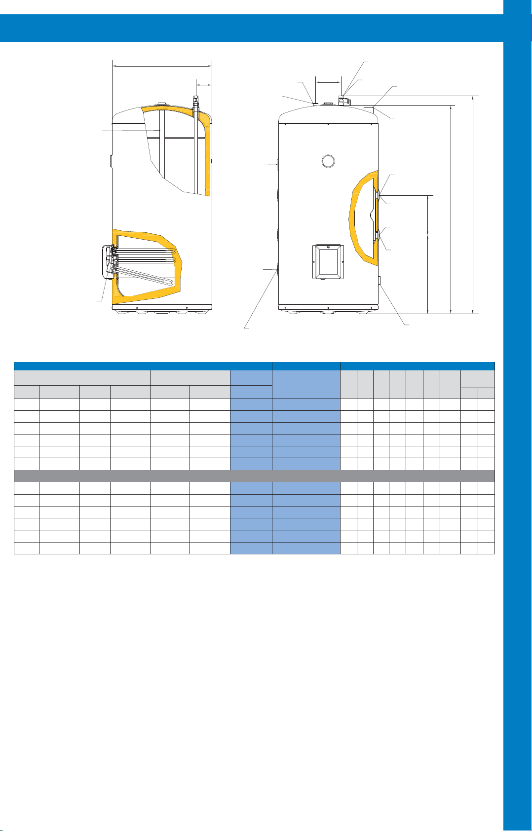
CARATTERISTICHE DEGLI SCALDACQUA - CHARACTERISTICS OF WATER HEATERS
Anodi in lega di magnesio AZ63
Magnesium anodes AZ63
Resistance-ThermostatUnits
Gruppi RT
D
F
Uscita H2O
Hot water exit
Mod.BSEBC 200-
300-400-500
Ricircolo
Recirculation
Scarico
Water drain
Ø1
i
Entrata H2O
Cold wa ter e ntry
Mod.BSEBC 200-300-400-500
Ø1
Ø2"
Uscita H2O
Hot water exit
Mod. BSEBC 800-1000
Mandata Termo
Thermo water entry
Ø2
Ø2
Ritorno Termo
Thermo water exit
1
h
H
3
h
S
C
A
L
2
h
D
A
Ø2" Mod. BSEBC 800-1000
Ø1"½ Mod.BSEBC 200-300-400-500
Entrata H2O
Cold water entry
Mod. BSEBC 800-1000
C
Q
CARATTERISTICHE/CHARACTERISTICS
S
CALDACQUA
W
ATERHEATERS
Unico Prelievo
Peso
Potenza Watt/Volt
Weight
Power Watt/Volt
3x1200
80
~220-230/380
3x1200
102
~220-230/380
3x2000
141
~220-230/380
3x2000
161
~220-230/380
3x3000
200
~220-230/380
6x1500
280
~220-230/380
3x1200
90
~220-230/380
3x1200
120
~220-230/380
3x2000
163
~220-230/380
3x2000
183
~220-230/380
3x3000
235
~220-230/380
6x1500
315
~220-230/380
* Fluido riscaldante termo 80°C.
** Temperatura acqua in entrata 15°C.
*** Termostato a 70 °C. Temperatura ingresso 15°C.
- Per i modelli (800-1000) valvola di sicurezza H
BSEBC = Boschetti Scaldacqua Elettrico Basamento Commerciale
BSETBC = Boschetti Scaldacqua Elettrico Termo Basamento Commerciale
Single Drawing
40°C - Lt. ***
400
600
800
1000
1600
2000
400
600
800
1000
1600
2000
Resa ΔT 45°C-Lt/h
Yield ΔT 45°C-Lt/h
69
69
115
115
172
172
69
69
115
115
172
172
SCAMBIATORE TERMO*
HEAT EXCHANGER *
Superficie
Surface m
2O non è a corredo.
Resa ΔT 45°C-Lt/h
2
Yield ΔT 45°C-Lt/h**
VERSIONE TERMO BILATERALE/BILATERAL THERMO VERSION
0,5
1
1,2
1,2
1,7
1,7
133
266
320
320
453
453
1) Serbatoi. Vengono costruiti con lamiera di adeguato spessore in rapporto al
diametro. Sono collaudati a 9 bar e garantiti per pressioni di 6 bar. Le esclusive
tecniche di stampaggio ed assemblaggio e l’attento pretrattamento di tutti i no-
stri serbatoi, permettono una accurata esecuzione della vetroporcellanatura per
mod. 200 - 300 - 400 - 500 e della zincatura per mod. 800 - 1000, con l’inseri-
mento di adeguati anodi in lega di magnesio (350 gr. per m2di lamiera).
2)
Scambiatori di calore. Il dimensionamento e relativo posizionamento garantisco-
no un ottimo scambio e l’uniformità di temperatura di tutto il contenuto degli appa-
recchi. Gli scambiatori sono eseguiti ad intercapedine con attacchi bilaterali.
3) Coibentazione. Viene eseguita con fibre di lana di vetro ad alta densità,
per un lungo mantenimento della temperatura.
4) Apparecchiature elettriche. Trattasi di gruppi resistenza - termostato 220
Volt monofase di ottima qualità, adeguata lunghezza e potenza, posizionati
per garantire un funzionamento ottimale, economia di energia ed il riscaldamento di tutta l’acqua contenuta. Possono funzionare, con gli opportuni col-
Capacità
Capacity
Lt.
200
300
400
500
800
1000
200
300
400
500
800
1000
* Heated fluid 80°C.
** Entry water temperature 15°C.
*** Thermostat 70°C. Entry water temperature 15°C.
- For models ( 800-1000) the H2O safety valve isn’t included.
1) Tanks. They are made in steel plate with a right thickness. They are tested
to 9 bar for working pressure of 6 bar. The exclusive pressing and assembling
techniques and the careful pre-treatment of our tanks, allow accurate execution of glass porcelainization for models 200 - 300 - 400 - 500 lt., and galvanization for models 800 - 1000 lt., furthermore into tanks we put a magnesium
anode according to the tank’s capacity (350 gr./m2steel plate).
2) Heat exchangers. The dimensions and the position allow excellent thermal exchange and uniform temperature. The heat exchangers have hollow
space and bilateral thermo connections.
3) The insulation is made up of high density glass wool to keep the tempera-
ture for a long time.
4) The electric equipments are 220 Volt monophase thermostat- resistance
unit best quality , with adequate lenght and power, put to grant perfect working, energy saving and water heating. They can work, thanks to the relative
connections, to 220 Volt monophase, to 220 Volt or 380 Volt triphase.
legamenti, a 220 Volt monofase oppure a 220 Volt o 380 Volt trifase.
MODELLO/MODEL
Modello
Model
BSEBC 200
BSEBC 300
BSEBC 400
BSEBC 500
BSEBC 800
BSEBC 1000
BSETBC 200
BSETBC 300
BSETBC 400
BSETBC 500
BSETBC 800
BSETBC 1000
D
mm
550
550
650
660
910
910
550
550
650
660
910
910
DIMENSIONI/DIMENSIONS
2
1
h
mm
1205
h
mm
h
3
mmFmm
H
mm
1155
1625
1675
1570
1640
1900
1970
1595
1940
1205
1155
1625
1570
1900
1595
1940
1675
1640
1970
435
435
460
460
460
560
220
490
490
490
490
490
90
90
90
90
90
90
90
90
i
mm
140
140
140
140
140
140
140
140
Attacchi
Connections
Ø1
Ø2
3/4”
3/4”
1”
1”
3/4”
1”
3/4”
1”
1”
1”
1”
1”
1”
1”
U
A
E
L
E
T
T
R
I
C
I
Quote e illustrazioni sono indicative. Il costruttore si riserva la facoltà di
apportare eventuali modifiche senza alcun preavviso.
Dimensions and pictures are only indicatives. The manufacturer has the
right to make changes without notice.
15
Page 18
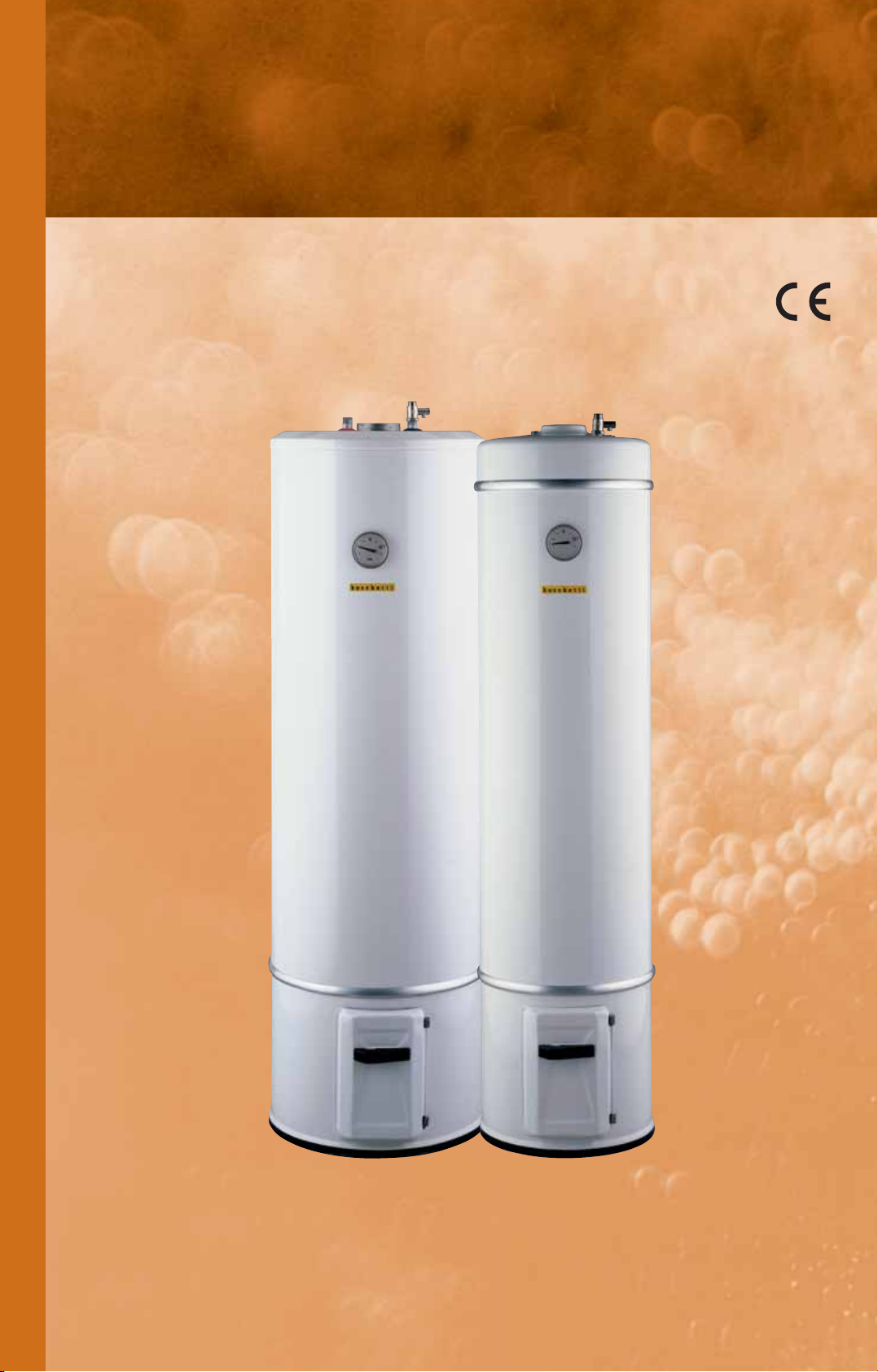
S
C
A
L
D
Scaldacqua a legna.
W
OOD WATER HEATERS.
Modelli/Models BL • BLE • BLET
A
C
Q
U
A
A
L
E
G
N
A
Page 19
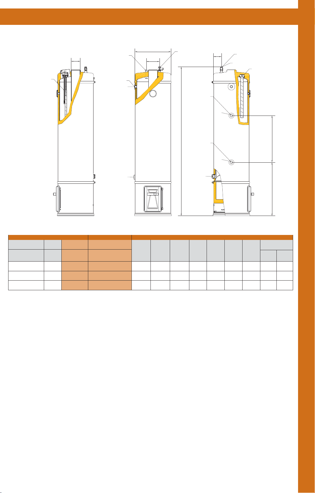
CARATTERISTICHE DEGLI SCALDACQUA - CHARACTERISTICS OF WATER HEATERS
Gruppo RT Gambo L.760
Resistance-Thermostat unit L.760
Mod. BLE
BLET
DF
Uscita H2O
Hot water exit
Attacco per valvola TP
Connection for TP valve
Mod. BL-E-T/115-150
Scarico
Water drain
D
i
½"
Entrata H2O
Cold water entry
Mandata Termo
Thermo water entry
H
Ritorno Termo
Thermo water exit
Mod. BL-E-T/80
Water drain
Scarico
F
Ø2
Ø2
Mod. BL
Valvola di sicurezza
Safety valve
Ø1
Anodo in lega di magnesio AZ63
Magnesium anode AZ63
2
h
1
h
S
C
A
L
D
A
C
CARATTERISTICHE/CHARACTERISTICS DIMENSIONI/DIMENSIONS
Legna - Elettrico
Wood - Electric
Watt/Volt
1000/~220-230
1000/~220-230
1000/~220-230
- Resa da 1000 Watt = Resa ΔT 45°C - 19 lt./h
BL = Boschetti Legna
BLE = Boschetti Legna Elettrico
BLET = Boschetti Legna Elettrico Termo
1) Serbatoi. Le esclusive tecniche di stampaggio ed assemblaggio e l’attento pretrattamento di tutti i nostri serbatoi, permettono un’accurata esecuzione della zincatura con l’inserimento di adeguati anodi in lega di magnesio
(gr. 350 per mq. di lamiera).
Per modelli: 80 lt. garanzia 3 anni pressione massima esercizio 8 bar
2) Scambiatori di calore. Il dimensionamento e relativo posizionamento garantiscono un ottimo scambio e l’uniformità di temperatura di tutto il contenuto degli apparecchi.
Gli scambiatori sono eseguiti: ad intercapedine con attacchi bilaterali su
tutti gli scaldacqua modello lt. 115 e 150; a doppio tubo con attacchi po-
steriori sugli apparecchi modello lt. 80.
Peso
Weight
Versione
Version
A3
57
87
90
115 - 150 lt. garanzia 3 anni pressione massima esercizio 8 bar
Capacità
Capacity
Lt.
80
115
150
MODELLO/MODEL
Modello
Model
BL 80 • BLE 80
BLET 80
BL 115 • BLE 115
BLET 115
BL 150 • BLE 150
BLET 150
D
mm
350
440
440
H
mm
1475
1485
1685
- Efficiency 1000 Watt = Efficiency ΔT 45°C - 19 lt./h
1) Tanks. The exclusive pressing and assembling techniques and the care-
ful pre-treatment of our tanks, allow accurate execution of galvanization and
fitting in of magnesium anode
(350 gr./m
For models: 80 lt. 3 years warranty maximum working pressure 8 bar
2) Heat exchangers: the dimensions and the position allow excellent thermal exchange and uniform temperature.
The heat exchangers have: hollow space and bilateral thermo connections
for all heaters model 115 and 150 lt.; double tube and back thermo con-
nections for heaters model 80 lt..
h1
mm
520
470
470
2
steel plate).
115 - 150 lt. 3 years warranty maximum working pressure 8 bar
h2
mm
460
420
420
mm
70
70
70
F
i
mm
130
120
120
mm
80
80
80
Q
U
Attacchi
DF
Connections
1/2”
1/2”
1/2”
Ø2Ø1
3/4”
3/4”
3/4”
A
A
L
E
G
N
A
3) Coibentazione. Viene eseguita con fibre di lana di vetro ad alta densità,
per un lungo mantenimento della temperatura.
4) Apparecchiature elettriche. Gli scaldacqua misto elettrici sono dotati di
gruppi resistenza-termostato 220 Volt monofase di ottima qualità, adeguata
lunghezza e potenza, posizionati per garantire un funzionam
ed il riscaldamento di tutta l’acqua contenuta.
5) Smaltatura del rivestimento esterno. Il rivestimento esterno è cotto a
forno a 220°C dopo un adeguato pretrattamento. Tutti i modelli hanno la fornella smaltata a 830°C garantendo brillantezza e resistenza di colpi, di graffi ed al fuoco.
Quote e illustrazioni sono indicative. Il costruttore si riserva la facoltà di
apportare eventuali modifiche senza alcun preavviso.
ento ottimale,
3) The insulation is made up of high density glass wool to keep the tempera-
ture for a long time.
4) Electric equipments. The electric wood water heaters have 220 Volt
monophase thermostat-resistance unit best quality, with adequate lenght
and power, put to grant perfect working and water heating.
5) External covering enameling. The external covering is 220°C furnace
cooked after adequate pre-treatment. All models have enamelled firebox
830°C temperature, grant brilliant surface, shocks, scratches and fire proof.
Dimensions and pictures are only indicatives. The manufacturer has the
right to make changes without notice.
17
Page 20
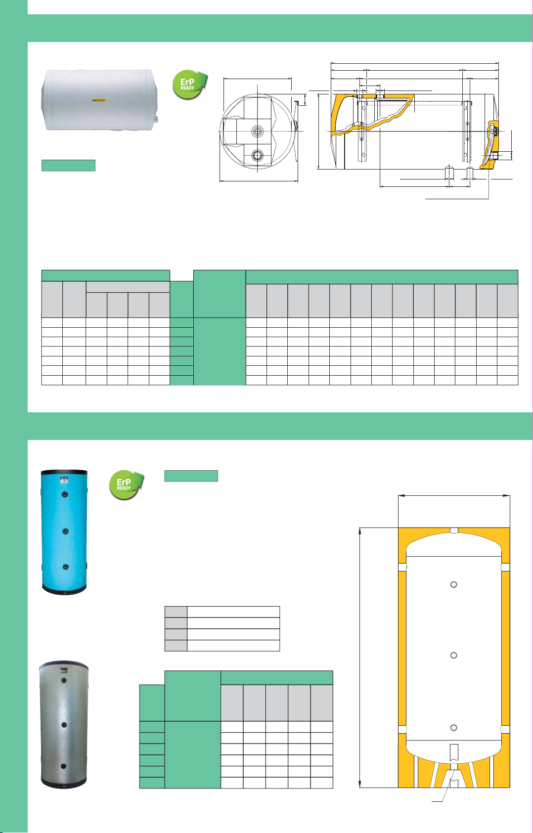
Entrata H2O
Cold water entry
Ø1
Uscita H2O
Hot water exit
G
h2
Anodo in lega di magnesio Az 63
Magnesium anode AZ63
Dr
L
L3
L4
L3
II
Ø2
Mandata Termo
Thermo water entry
L1
L2
L1
I1 I
Ritorno Termo
Thermo water exit
Ø2
1"1/4 Gas
Ds
Ø1
Lt/h
Superficie
m
2
CapacitàLtResa
Kcal/h
Resa
ΔT 45° C
lt/h
Caratteristiche Tecniche
*Scambiatore - Termo
Por tata
Fluido
Riscaldante
Lt
Capacità
Bollitori
Kg
Bollitore
Peso
D
s
mm
D
r
mmLmm
L
1
mm
L
2
mm
L
3
mm
L
4
mm
G
mm
Dim ensioni Bollit ori
ImmI
1
mm
h
2
mm
Ø1Ø
2
480 0,4 4,9 4800 106 8038 410 440 825 165 495 220 385 120 255 70 460 3/4” 1”1/4
660 0,55 6,7 6600 147 10046 410 440 985 170 645 212,5 560 120 405 70 460 3/4” 1”1/4
1000 0,86 10,5 10320 230 12551 410 440 1210 160 890 325 560 120 650 70 460 3/4” 1”1/4
1400 1,17 14,2 14040 312 20073 450 510 1490 172,5 1145 452,5 585 180 785 107,5 520 1”1/4 1”1/4
2000 1,68 20,3 20160 448 300100 500 560 1830 217,5 1395 482,5 865 180 1035 132,5 580 1”1/4 1”1/2
2900 2,42 30,3 29040 645 500159 600 660 2100 227,5 1645 442,5 1215 180 1285 182,5 680 1”1/4 1”1/2
Modello
1000 0,9 11 10800 240 15061 450 490 1150 157,5 835 282,5 585 120 595 95 505
1”1/4
1”1/4
BDPO3R
*Fluido riscaldante termo 80°C. *Heated fluid 80°C.
Bollitore Doppia Parete
Orizzontale 3 anni Rivestito
- BDPO3R =
•
Coibentazione in poliuretano espanso
senza CFC, HFC, HCFC
•
Serbatoio teflonato
•
Pressione massima d’esercizio serbatoio 6 bar
•
Scambiatore funzionante acqua termo max 3 bar
•
Involucro in lamierino verniciato bianco per i modelli:
BDPO3R - BDPO3R 80 - 100 - 125 - 150
In Skay per gli altri modelli
•
The insulation is made up of polyurethane foam
CFC free, HFC free and HCFC free
•
Enameled tank
•
Tank maximum working pressure 6 bar
•
Thermo exchanger: it works with water max 3 bar
•
For models: BDPO3R - BDPO3R 80 - 100 - 125 - 150
the covering is made in steel plate white enameled
For other models there is Skay covering
MODELLI
Bollitori Doppia Parete Orizzontali 3 anni Rivestiti - mod. BDPO3R
(Horizontal boilers with hollow space 3 years warranty - mod. BDPO3R)
Serbatoi per Acqua Refrigerata ed Acqua Calda - mod. SAR
(Tanks for cooled water and hot water - mod. SAR)
SKAY
ALLUMINIO
Modello
SAR/SKAY
SAR/AL
Lt
Capacità
Serbatoi
100
200
300
500
750
1000
DmmHTmmA So - T S
470
520
620
720
820
870
1000
1370
1400
1680
1830
2000
1"1/4
2"
3"
3"
3"
3"
1/2"
1/2"
1/2"
1/2"
1/2"
1/2"
1"1/4
1"1/4
1"1/4
1"1/4
1"1/4
1"1/4
Dim ensioni Serbat oi
- SAR/SKAY = Serbatoio Acqua Refrigerata rivestito in SKAY
- SAR/AL = Serbatoio Acqua Refrigerata rivestito in alluminio
• Pressione max d’esercizio 6 bar
• Coibentazione in poliuretano iniettato
e finitura esterna in skay oppure alluminio
• Serbatoio zincato
• Maximum working pressure 6 bar
• The insulation is made up of injected polyurethane
and the external finishing is made in skay or aluminum.
• Galvanized tank
MODELLI
A
So
T
S
Entrata - Uscita
Sonda
Termometro
Scarico
A
A
D
1"1/4
A
T
A
S
HT
So
So
Quote e illustrazioni sono indicative. Il costruttore si riserva la facoltà di apportare eventuali modifiche senza alcun preavviso.
Dimensions and pictures are only indicatives. The manufacturer has the right to make changes without notice.
B
O
L
L
I
T
O
R
I
A
S
E
R
P
E
N
T
I
N
O
E
S
E
R
B
A
T
O
I
18
Page 21
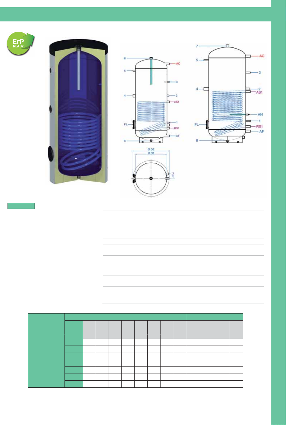
Quote e illustrazioni sono indicative. Il costruttore si riserva la facoltà di apportare eventuali modifiche senza alcun preavviso.
Dimensions and pictures are only indicatives. The manufacturer has the right to make changes without notice.
Bollitori serpentino saldato verticali - mod. BSSV
(Vertical boiler with welded coil - mod. BSSV)
BSSV 750-1000BSSV 150-500
Modello
Dimensioni Bollitori
Caratteristiche tecniche
Capacità
Bollitori
D1 D2 Altezza AF AC FL RS1 AS1
Scambiatore solare
Peso
Serpentino
superficie
Serpentino
contenuto
Lt Ø Ø H H H H H H m² Lt Kg
BSSV
150 559 68
200 703 80
300 798 108
400 763 131
500 848 144
750 941 199
1000
500
500
550
650
650
750
790
600
600
650
750
750
950
990
1053
1328
1532
1502
1777
2055
2060
132
132
138
143
143
237
243
904
1177
1398
1368
1633
1815
1820
323
323
358
376
376
374
380
259
253
278
303
303
336
342
1077
0,6
1,0
1,4
1,5
1,8
2,4
3
4,0
7,0
9,0
9,5
12,0
15,9
19,8
221
1
Sonda Ø20 (BSSV 150…500)
Sonda 1/2” (BSSV 750-1000)
2
Ricircolo 1”
3
Sonda Ø20 (BSSV 150…500)
Sonda 1/2” (BSSV 750-1000)
4
Resistenza elettrica 1”½
5
Termometro 1/2”
6
Anodo al magnesio 1”½
AN
Anodo elettronico 1/2”
AS1
Mandata solare 1”
RS1
Ritorno solare 1”
FL
Flangia di ispezione Ø180
AF
Entrata acqua fredda 1” (BSSV 150…500)
Entrata acqua fredda 1”¼ (BSSV 750-1000)
AC
Uscita acqua calda 1” (BSSV 150…500)
Uscita acqua calda 1”¼ (BSSV 750-1000)
1
Sensor Ø20 (BSSV 150…500)
Sensor 1/2” (BSSV 750-1000)
2
Recirculation 1”
3
Sensor Ø20 (BSSV 150…500)
Sensor 1/2” (BSSV 750-1000)
4
Electrical heating resistance 1”½
5
Thermometer 1/2”
6
Magnesium anode 1”½
AN
Electronic anode 1/2”
AS1
Solar flow 1”
RS1
Solar return 1”
FL
Inspection flange Ø180
AF
Cold water inlet 1” (BSSV 150…500)
Cold water inlet 1”¼ (BSSV 750-1000)
AC
Hot water outlet 1” (BSSV 150…500)
Hot water outlet
1”¼ (BSSV 750-1000)
7
Sfiato o valvola di sicurezza 1”½
8
Scarico 3/4” (BSSV 150…500)
Scarico 1”½ (BSSV 750-1000)
7
Security vent valve 1”½
8
Drainage 3/4” (BSSV 150…500)
Drainage 1”½ (BSSV 750-1000)
- BSSV = Bollitore Serpentino Saldato Verticale
MODELLI
•
Pressione massima d’esercizio serbatoio 6 bar
•
Temperatura massima d’esercizio 95°C
•
Rivestimento in schiuma di poliuretano rigido 50 mm
per i modelli fino a 500 Litri
•
Isolamento morbido 100 mm fornito separatamente
per i modelli 750 e 1000 Litri
•
Serbatoio vetrificato
•
Gli scambiatori a serpentino possono funzionare
ad acqua termo o solare max 10 bar
•
Storage tank Pmax 6 bar
•
Storage tank Tmax 95°C
•
Hard polyurethane foam, 50 mm till 500 ltrs capacity
•
Soft polyester fibre 100 mm on demand
for the 750 and 1000 ltrs models
•
Glass lined tank
•
Exchanger Pmax 10 bar heated water and solar
B
O
L
L
I
T
O
R
I
A
S
E
R
P
E
N
T
I
N
O
E
S
E
R
B
A
T
O
I
19
Page 22
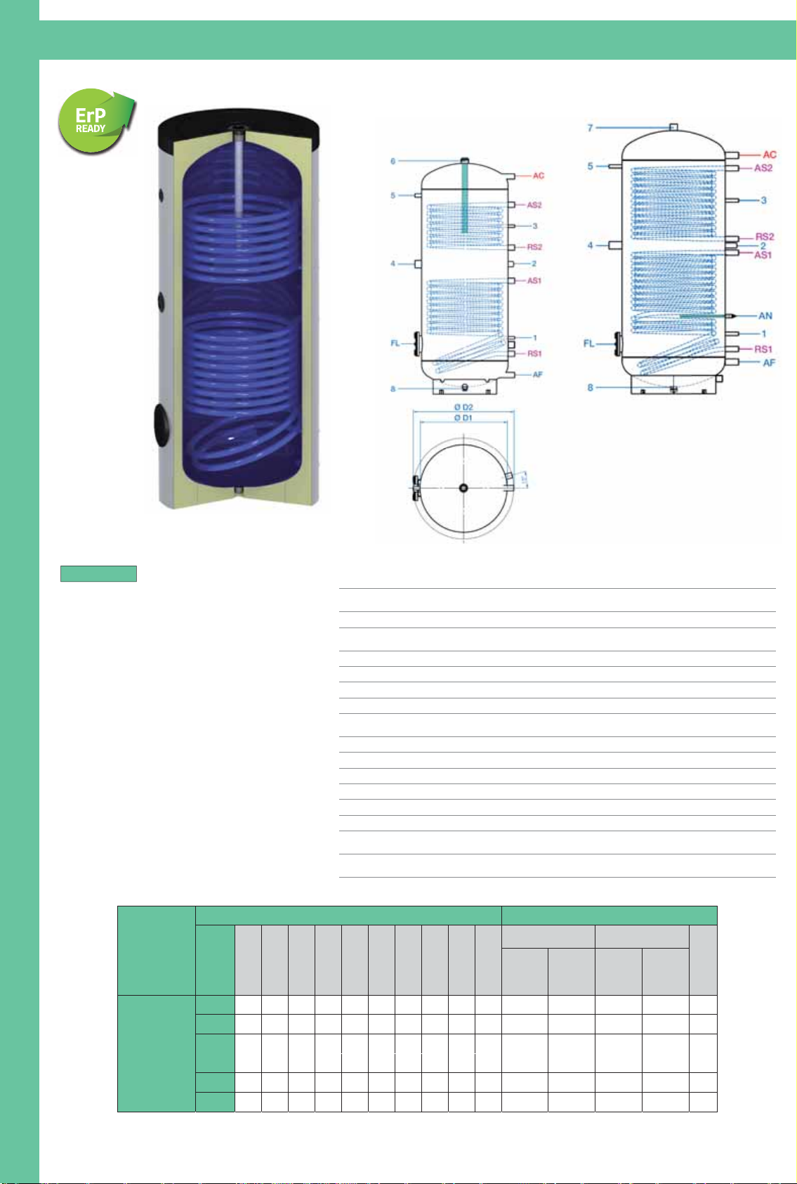
Quote e illustrazioni sono indicative. Il costruttore si riserva la facoltà di apportare eventuali modifiche senza alcun preavviso.
Dimensions and pictures are only indicatives. The manufacturer has the right to make changes without notice.
Bollitori 2 serpentini saldati verticali - mod. B2SSV
(Vertical boiler with 2 welded coils - mod. B2SSV)
- B2SSV = Bollitore 2 Serpentini Saldati Verticale
MODELLI
•
Pressione massima d’esercizio serbatoio 6 bar
•
Temperatura massima d’esercizio 95°C
•
Rivestimento in schiuma di poliuretano rigido 50 mm
per i modelli fino a 500 Litri
•
Isolamento morbido 100 mm fornito separatamente
per i modelli 750 e 1000 Litri
•
Serbatoio vetrificato
•
Gli scambiatori a serpentino possono funzionare
ad acqua termo o solare max 10 bar
•
Storage tank Pmax 6 bar
•
Storage tank Tmax 95°C
•
Hard polyurethane foam, 50 mm till 500 ltrs capacity
•
Soft polyester fibre 100 mm on demand
for the 750 and 1000 ltrs models
•
Glass lined tank
•
Exchanger Pmax 10 bar heated water and solar
Modello
Dimensioni Bollitori Caratteristiche tecniche
Capacità
Bollitori
D1 D2
Altezza AF AC FL RS1 AS1 RS2 AS2
Scambiatore superiore
termo
Scambiatore inferiore
solare
Peso
Serpentino
sopra
superficie
Serpentino
sopra
contenuto
Serpentino
sotto
superficie
Serpentino
sotto
contenuto
Lt Ø Ø H H H H H H H H m² Lt m² Lt Kg
B2SSV
200 500 600 1328 132 1177 323 253 703 810 1050 0,6 4,0 1,0 7,0 90
300 550 650 1532 138 1398 358 278 798 898 1228 1,0 7,0 1,4 9,0 124
400 650 750 1502 143 1368 376 303 763 903 1183 1,0 7,0 1,5 9,5 146
500 650 750 1777 143 1633 376 303 848 1098 1420 1,2 8,0 1,8 12,0 160
750 750 950 2055 237 1815 374 336 941 1266 1716 1,8 11,9 2,4 15,9 227
1000 790 990 2060 243 1820 380 342 1077 1182 1722 2,4 15,9 3,0 19,8 252
1
Sonda Ø20 (B2SSV 200…500)
Sonda 1/2” (B2SSV 750-1000)
2
Ricircolo 1”
3
Sonda Ø20 (B2SSV 200…500)
Sonda 1/2” (B2SSV 750-1000)
4
Resistenza elettrica 1”½
5
Termometro ½”
6
Anodo al magnesio 1”½
AN
Anodo elettronico 1/2”
AS1
Mandata solare 1”
RS1
Ritorno solare 1”
AS2
Mandata caldaia 1”
RS2
Ritorno caldaia 1”
FL
Flangia di ispezione Ø180
AF
Entrata acqua fredda 1” (B2SSV 200…500)
Entrata acqua fredda 1”¼ (B2SSV 750-1000)
AC
Uscita acqua calda 1” (B2SSV 200…500)
Uscita acqua calda 1”¼ (B2SSV 750-1000)
1
Sensor Ø20 (B2SSV 200…500)
Sensor 1/2” (B2SSV 750-1000)
2
Recirculation 1”
3
Sensor Ø20 (B2SSV 200…500)
Sensor 1/2” (B2SSV 750-1000)
4
Electrical heating resistance 1”½
5
Thermometer 1/2”
6
Magnesium anode 1”½
7
Sfiato o valvola di sicurezza 1”½
7
Security vent valve 1”½
AN
Electronic anode 1/2”
AS1
Solar flow 1”
RS1
Solar return 1”
AS2
Boiler flow 1”
RS2
Boiler return 1”
FL
Inspection flange Ø180
AF
Cold water inlet 1” (B2SSV 200…500)
Cold water inlet 1”¼ (B2SSV 750-1000)
AC
Hot water outlet 1” (B2SSV 200…500)
Hot water outlet 1”¼ (B2SSV 750-1000)
8
Scarico 3/4” (B2SSV 200…500)
Scarico 1”½ (B2SSV 750-1000)
8
Drainage 3/4” (B2SSV 200…500)
Drainage 1”½ (B2SSV 750-1000)
B2SSV 750-1000B2SSV 200-500
B
O
L
L
I
T
O
R
I
A
S
E
R
P
E
N
T
I
N
O
E
S
E
R
B
A
T
O
I
20
Page 23
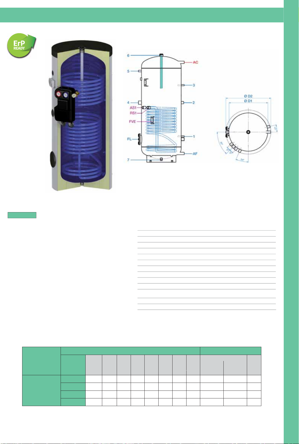
Quote e illustrazioni sono indicative. Il costruttore si riserva la facoltà di apportare eventuali modifiche senza alcun preavviso.
Dimensions and pictures are only indicatives. The manufacturer has the right to make changes without notice.
Bollitori serpentino saldato verticali Plus (per pannelli solari) - mod. BSSV PLUS
(Vertical boiler with welded coil Plus (for solar panels) - mod. BSSV PLUS)
- BSSV PLUS = Bollitore Serpentino Saldato Verticale Plus
(per pannelli solari)
MODELLI
•
Pressione massima d’esercizio serbatoio 6 bar
•
Temperatura massima d’esercizio 95°C
•
Rivestimento in schiuma di poliuretano rigido 50 mm
•
Serbatoio vetrificato
•
Gli scambiatori a serpentino possono funzionare
ad acqua termo o solare max 10 bar
•
Il bollitore è dotato di gruppo solare due linee
e centralina solare a singolo circuito,
premontati ed installati in fabbrica.
•
Addizionalmente il bollitore è predisposto per rendere
possibile il fissaggio del vaso di espansione solare.
•
Storage tank Pmax 6 bar
•
Storage tank Tmax 95°C
•
Hard polyurethane foam 50 mm
•
Glass lined tank
•
Exchanger Pmax 10 bar heated water and solar
•
The boiler is equipped with a pre-mounted two lines solar
station and an electrically connected solar control unit.
•
Furthermore the boiler provides the possibility
for fixing the solar expansion vessel.
1 Pozzetto per sonda Ø20
2 Ricircolo 1”
3 Pozzetto per sonda Ø20
4
Resistenza elettrica 1”½
5 Manicotto per termometro 1/2”
6 Anodo al magnesio 1”½
AS1 Mandata solare 1”
RS1 Ritorno solare 1”
FL Flangia di ispezione Ø180
FVE
Fissaggio per kit vaso di
espansione 2 x M8
AF Entrata acqua fredda 1”
AC
1
2
3
4
5
6
AS1
RS1
FL
FVE
AF
AC Uscita acqua calda 1”
Immersion sleeve for sensor Ø20
Recirculation 1”
Immersion sleeve for sensor Ø20
Electrical heating resistance 1”½
Connection for thermometer 1/2”
Magnesium anode 1”½
7 Scarico 3/4” 7
Drainage 3/4”
Solar flow 1”
Solar return 1”
Inspection flange Ø180
Fixing for expansion kit
2 x M8
Cold water inlet 1”
Hot water outlet 1”
Modello
Dimensioni Bollitori Caratteristiche tecniche
Capacità
Bollitori
D1 D2 Altezza AF AC FL RS1 AS1
Scambiatore solare
Peso
Ø Ø H H H H H H
BSSV PLUS
200 500 600 1328 132 1177 323 676 676 1,0 7,0 85
300 550 650 1532 138 1398 358 768 768 1,4 9,0 113
400 650 750 1502 143 1368 377 753 753 1,5 9,5 136
500 650 750 1777 143 1633 377 893 893 1,8 12,0 149
Serpentino
superficie
Serpentino
contenuto
m² Lt KgLt
B
O
L
L
I
T
O
R
I
A
S
E
R
P
E
N
T
I
N
O
E
S
E
R
B
A
T
O
I
21
Page 24
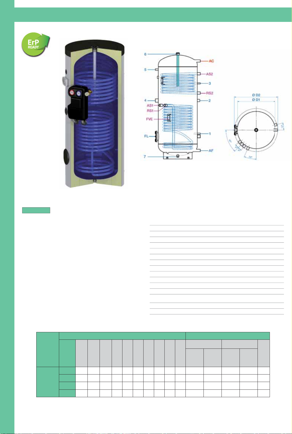
Quote e illustrazioni sono indicative. Il costruttore si riserva la facoltà di apportare eventuali modifiche senza alcun preavviso.
Dimensions and pictures are only indicatives. The manufacturer has the right to make changes without notice.
Bollitori 2 serpentini saldati verticali Plus (per pannelli solari) - mod. B2SSV PLUS
(Vertical boiler with 2 welded coils Plus (for solar panels) - mod. B2SSV PLUS)
- B2SSV PLUS = Bollitore 2 Serpentini Saldati Verticale Plus
(per pannelli solari)
MODELLI
•
Pressione massima d’esercizio serbatoio 6 bar
•
Temperatura massima d’esercizio 95°C
•
Rivestimento in schiuma di poliuretano rigido 50 mm
•
Serbatoio vetrificato
•
Gli scambiatori a serpentino possono funzionare
ad acqua termo o solare max 10 bar
•
Il bollitore è dotato di gruppo solare due linee
e centralina solare a singolo circuito,
premontati ed installati in fabbrica.
•
Addizionalmente il bollitore è predisposto per rendere
possibile il fissaggio del vaso di espansione solare.
•
Storage tank Pmax 6 bar
•
Storage tank Tmax 95°C
•
Hard polyurethane foam 50mm
•
Glass lined tank
•
Exchanger Pmax 10 bar heated water and solar
•
The boiler is equipped with a pre-mounted two lines solar station
and an electrically connected solar control unit.
•
Furthermore the boiler provides the possibility for fixing
the solar expansion vessel.
1 Pozzetto per sonda Ø20
2 Ricircolo 1”
3 Pozzetto per sonda Ø20
5 Manicotto per termometro 1/2”
6 Anodo al magnesio 1”½
AS1 Mandata solare 1”
RS1 Ritorno solare 1”
1
2
3
5
6
AS1
RS1
Immersion sleeve for sensor Ø20
Recirculation 1”
Immersion sleeve for sensor Ø20
4 Resistenza elettrica 1”½ 4
Electrical heating resistance 1”½
Connection for thermometer 1/2”
Magnesium anode 1”½
7 Scarico 3/4” 7
Drainage 3/4”
Solar flow 1”
Solar return 1”
AS2 Mandata caldaia 1”
RS2 Ritorno caldaia 1”
FL Flangia di ispezione Ø180
FVE
Fissaggio per kit vaso di
espansione 2 x M8
AF Entrata acqua fredda 1”
AC
AS2
RS2
FL
FVE
AF
ACUscita acqua calda 1”
Boiler flow 1”
Boiler return 1”
Inspection flange Ø180
Fixing for expansion kit
2 x M8
Cold water inlet 1”
Hot water outlet 1”
Modello
Dimensioni Bollitori Caratteristiche tecniche
Capacità D1 D2
Altezza AF AC FL RS1 AS1 RS2 AS2
Scambiatore superiore
termo
Scambiatore inferiore
solare
Peso
Serpentino
sopra
superficie
Serpentino
sopra
contenuto
Serpentino
sotto
superficie
Serpentino
sotto
contenuto
Lt Ø Ø H H H H H H H H
m² Lt m² Lt Kg
B2SSV
PLUS
200 500 600 1328 132 1177 323 676 676 810 1050 0,6 4,0 1,0 7,0 95
300 550 650 1532 138 1398 358 768 768 898 1228 1,0 7,0 1,4 9,0 129
400 650 750 1502 143 1368 376 753 753 903 1183 1,0 7,0 1,5 9,5 151
500 650 750 1777 143 1633 376 893 893 1098 1420 1,2 8,0 1,8 12,0 165
B
O
L
L
I
T
O
R
I
A
S
E
R
P
E
N
T
I
N
O
E
S
E
R
B
A
T
O
I
22
Page 25
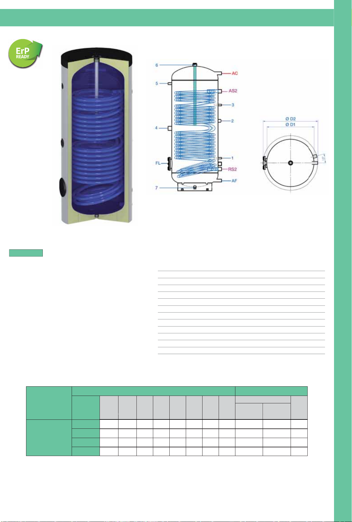
Quote e illustrazioni sono indicative. Il costruttore si riserva la facoltà di apportare eventuali modifiche senza alcun preavviso.
Dimensions and pictures are only indicatives. The manufacturer has the right to make changes without notice.
Bollitori serpentino saldato maggiorato verticali (per pompa di calore) - mod. BSSMV
(Vertical boiler with high power welded coil (for heat pump) - mod. BSSMV)
- BSSMV = Bollitore Serpentino Saldato Maggiorato Verticale
(per pompa di calore)
MODELLI
•
Pressione massima d’esercizio serbatoio 6 bar
•
Temperatura massima d’esercizio 95°C
•
Rivestimento in schiuma di poliuretano rigido 50 mm
•
Serbatoio vetrificato
•
Gli scambiatori a serpentino possono funzionare
ad acqua termo o solare max 10 bar
•
Storage tank Pmax 6 bar
•
Storage tank Tmax 95°C
•
Hard polyurethane foam 50 mm
•
Glass lined tank
•
Exchanger Pmax 10 bar heated water and solar
1 Sonda Ø20
2 Ricircolo 1”
3 Sonda Ø20
4 Resistenza elettrica 1”½
5 Termometro 1/2”
6 Anodo al magnesio 1”½
7 Scarico 3/4”
AS2 Mandata caldaia 1”
RS2 Ritorno caldaia 1”
FL Flangia di ispezione Ø180
AF Entrata acqua fredda 1”
AC
1
2
3
4
5
6
7
AS2
RS2
FL
AF
AC Uscita acqua calda 1”
Sensor Ø20
Recirculation 1”
Sensor Ø20
Electrical heating resistance 1”½
Thermometer 1/2”
Magnesium anode 1”½
Drainage 3/4”
Boiler flow 1”
Boiler return 1”
Inspection flange Ø180
Cold water inlet 1”
Hot water outlet 1”
Modello
Dimensioni Bollitori Caratteristiche tecniche
Capacità
Bollitori
D1 D2 Altezza AF AC FL RS2 AS2
Scambiatore termo
Peso
Serpentino
superficie
Serpentino
contenuto
Lt Ø Ø H H H H H H m² Lt Kg
BSSMV
200 500 600 1328 132 1177 323 253 1050 2,8 14,0 110
300 550 650 1532 138 1398 358 278 1228 3,7 18,0 135
400 650 750 1502 143 1368 376 303 1183 4,7 30,0 165
500 650 750 1777 143 1633 376 303 1386 5,8 37,0 198
B
O
L
L
I
T
O
R
I
A
S
E
R
P
E
N
T
I
N
O
E
S
E
R
B
A
T
O
I
23
Page 26
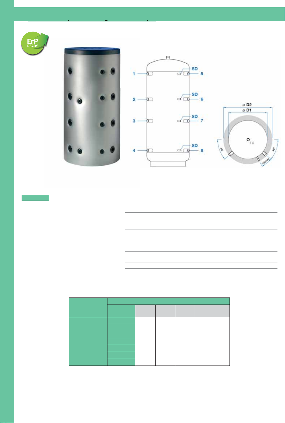
Quote e illustrazioni sono indicative. Il costruttore si riserva la facoltà di apportare eventuali modifiche senza alcun preavviso.
Dimensions and pictures are only indicatives. The manufacturer has the right to make changes without notice.
Serbatoio “Puffer” verticale (senza scambiatore) - mod. SPUV
(Floor standing vertical tank (no coil) “Puffer” - mod. SPUV)
(g (
- SPUV = Serbatoio “Puffer” Verticale
(senza scambiatore)
MODELLI
•
Pressione massima d’esercizio serbatoio 3 bar
•
Temperatura massima d’esercizio 95°C
•
Rivestimento in schiuma di poliuretano rigido 50 mm
per i modelli fino a 500 Litri
•
Isolamento morbido 100 mm fornito separatamente
per gli altri modelli
•
Serbatoio internamente al grezzo,
trattato esternamente con vernice antiruggine
•
Maximum operating pressure 3 bar
•
Maximum operating temperature 95°C
•
Hard polyurethane foam, 50 mm till 500 ltrs capacity
•
Soft polyester fibre 100 mm on demand for the other models
•
Steel tank with any internal anti-corrosion treatment
with external protection paint only
Modello
Dimensioni Serbatoi
Caratteristiche tecniche
Capacità
Serbatoi
D1 D2 Altezza Peso
Lt Ø Ø H Kg
SPUV
300 550 650 1357 57
500 650 750 1637 79
800 790 990 1760 97
1000 790 990 2090 114
1250 950 1150 2060 146
1500 1000 1200 2200 162
2000 1100 1300 2420 225
1 Mandata caldaia 1”½
2 Mandata riscaldamento 1”½
3 Libero a disposizione 1”½
4 Ritorno riscaldamento 1”½
5
Mandata riscaldamento alta
temperatura 1”½
6
Mandata riscaldamento bassa
temperatura 1”½
7
Ritorno caldaia a gas, gasolio, pellet 1”½
8 Ritorno caldaia a legna 1”½
SD Sonde per il controllo riscaldamento ½”
Boiler flow 1”½ 1
2
3
4
5
6
7
8
SD
Heating system flow 1”½
Free disposal 1”½
Return of heating system 1”½
Heating flow high temperature 1”½
Heating flow low temperature 1”½
Gas, fuel or pellet boiler return 1”½
Wood boiler return 1”½
Sensor for heating system ½”
B
O
L
L
I
T
O
R
I
A
S
E
R
P
E
N
T
I
N
O
E
S
E
R
B
A
T
O
I
24
Page 27
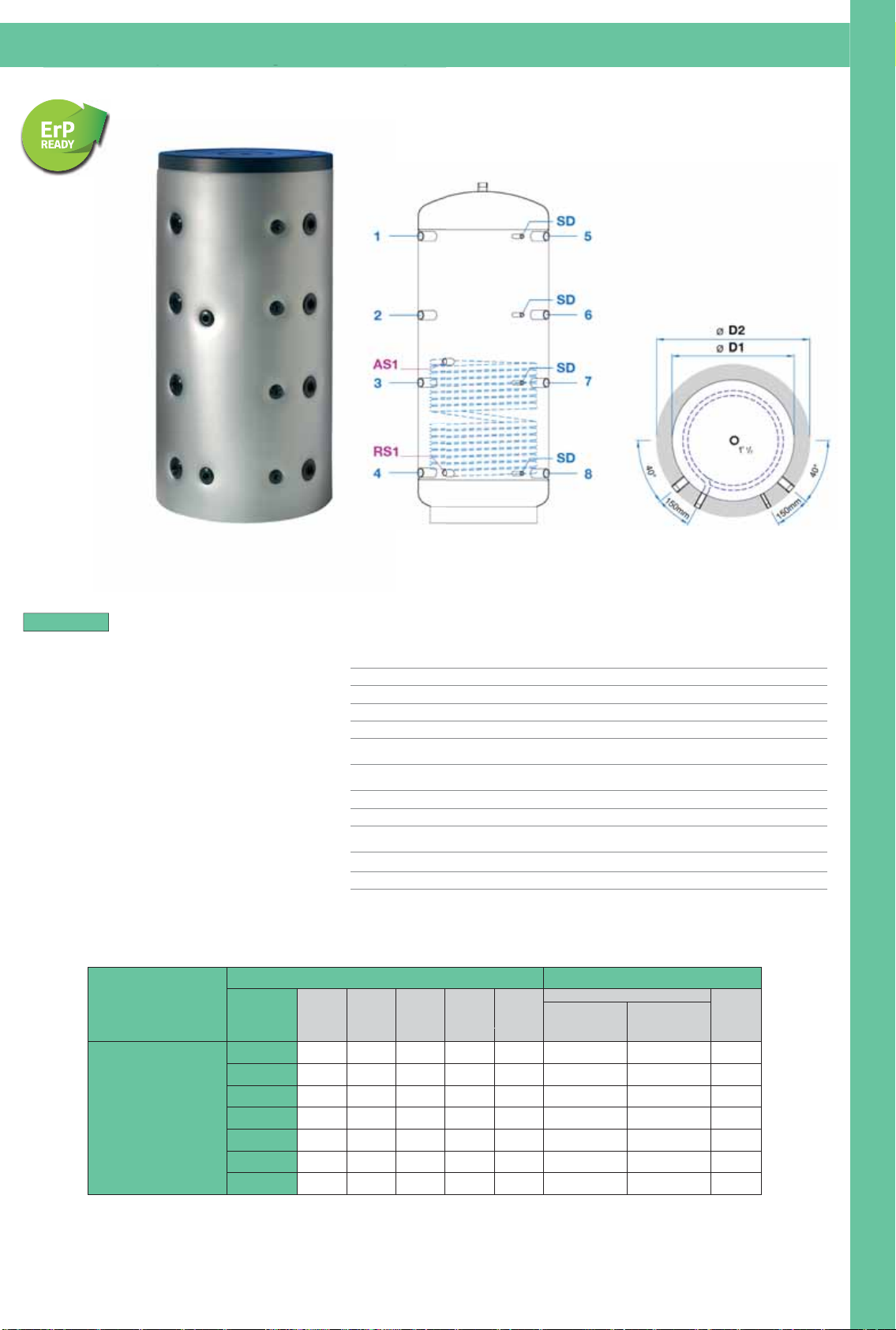
Quote e illustrazioni sono indicative. Il costruttore si riserva la facoltà di apportare eventuali modifiche senza alcun preavviso.
Dimensions and pictures are only indicatives. The manufacturer has the right to make changes without notice.
Serbatoio “Puffer” con scambiatore verticale - mod. SPUSV
(Floor standing vertical tank (with coil) “Puffer” - mod. SPUSV)
- SPUSV = Serbatoio “Puffer” con Scambiatore
verticale
MODELLI
•
Pressione massima d’esercizio serbatoio 3 bar
•
Temperatura massima d’esercizio 95°C
•
Rivestimento in schiuma di poliuretano rigido 50 mm
per i modelli fino a 500 Litri
•
Isolamento morbido 100 mm fornito separatamente
per gli altri modelli
•
Serbatoio internamente al grezzo,
trattato esternamente con vernice antiruggine
•
Gli scambiatori a serpentino possono funzionare
ad acqua termo o solare max 10 bar
•
Maximum operating pressure 3 bar
•
Maximum operating temperature 95°C
•
Hard polyurethane foam, 50 mm till 500 ltrs capacity
•
Soft polyester fibre 100 mm on demand for the other models
•
Steel tank with any internal anti-corrosion treatment
with external protection paint only
•
Exchanger Pmax 10 bar heated water and solar
(g (
1 Mandata caldaia 1”½
2 Mandata riscaldamento 1”½
3 Libero a disposizione 1”½
4 Ritorno riscaldamento 1”½
5
Mandata riscaldamento alta
temperatura 1”½
6
Mandata riscaldamento bassa
temperatura 1”½
7
Ritorno caldaia a gas, gasolio, pellet 1”½
8 Ritorno caldaia a legna 1”½
SD
Sonde per il controllo riscaldamento e
solare 1/2”
AS1 Mandata solare 1”
RS1 Ritorno solare 1”
1 Boiler flow 1”½
2 Heating system flow 1”½
3 Free disposal 1”½
4 Return of heating system 1”½
5
Heating flow high temperature 1”½
6
Heating flow low temperature 1”½
7 Gas, fuel or pellet boiler return 1”½
8 Wood boiler return 1”½
SD
Sensor for heating and solar system 1/2”
AS1 Solar flow 1”
RS1 Solar return 1”
Modello
Dimensioni Serbatoi Caratteristiche tecniche
Capacità
Serbatoi
D1 D2 Altezza RS AS
Scambiatore solare
Peso
Serpentino
superficie
Serpentino
contenuto
Lt Ø Ø H H H m² Lt Kg
SPUSV
300 550 650 1357 210 660 1,2 7,9 73
500 650 750 1637 211 721 1,8 11,9 103
800 790 990 1760 256 801 2,4 15,9 130
1000 790 990 2090 300 970 3,0 19,8 156
1250 950 1150 2060 300 970 3,0 19,8 189
1500 1000 1200 2200 350 1000 3,6 23,7 210
2000 1100 1300 2420 325 1105 4,2 27,7 278
B
O
L
L
I
T
O
R
I
A
S
E
R
P
E
N
T
I
N
O
E
S
E
R
B
A
T
O
I
25
Page 28
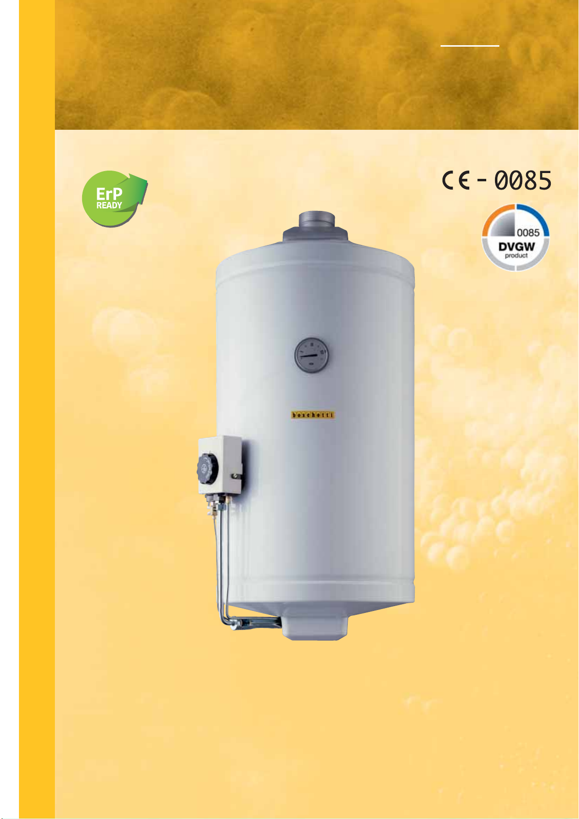
S
C
A
L
D
A
C
Q
Scaldacqua multigas ad accumulo a parete.
S
TORAGE MULTIGAS WALL WATER HEATERS.
Modelli/Models BGM/ • BGMT/
U
A
M
U
L
T
G
A
S
I
PROGETTATO CON BASSO COEFFICIENTE DI DISPERSIONE DI CALORE E ALTO RENDIMENTO
CON EVAPORAZIONE CONDENSA SECONDO DIN EN 89
EQUIPMENT DESIGNED WITH LOW THERMAL TRANSMITTANCE, HIGH THERMAL EFFICIENCY
AND MOISTURE’S EVAPORATION IN ACCORDING TO THE RULE DIN EN 89
Page 29
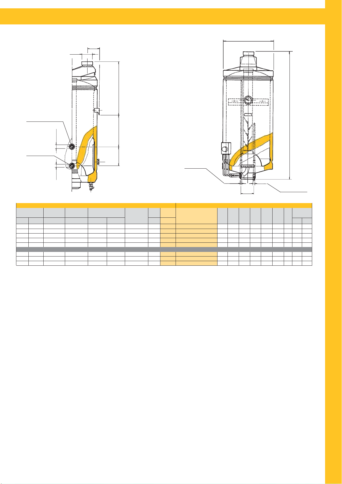
CARATTERISTICHE DEGLI SCALDACQUA - CHARACTERISTICS OF WATER HEATERS
D
L
DF
h1
S
Mandata Termo
Thermo water entry
Ø2
Ritorno Termo
Thermo water exit
Ø2
Portata termica
Thermal capacity
Kw
4,6
5,3
5,3
5,3
5,3
5,3
5,3
5,3
* Fluido riscaldante 80°C.
** Temperatura in entrata 15°C.
*** Termostato a 70°C. Temperatura ingresso 15°C.
- Su richiesta disponibile Gas Liquido G30-3+ (BGM/G.P.L.).
BGM/ = Boschetti Gas Metano
BGMT/ = Boschetti Gas Metano Termo
Unico Prelievo
Single Drawing
Kcal/h ***Lt
4000
4500
4500
4500
4500
4500
4500
4500
40°C
100
160
200
240
280
160
200
280
Resa ΔT 45°C
Yield ΔT 45°C
**Lt/h
75
85
85
85
85
85
85
85
Consumo
Consumption
Metano
3
m
/h
0,49
0,56
0,56
0,56
0,56
0,56
0,56
0,56
h3
h2
Scambiatore*
Resa ΔT 45°C-Lt/h
Heat Exchanger*
GPL
Yield ΔT 45°C-Lt/h
kg/h
0,36
0,42
0,42
0,42
0,42
VERSIONE TERMO BILATERALE/BILATERAL THERMO VERSION
0,42
0,42
0,42
Peso
Capacità
Weight
Capacity
Lt.Kg.
50
26
80
33
100
41
120
51
140
56
80
80
85
85
85
37
100
45
140
61
* Heated fluid 80°C.
** Entry water temperature 15°C.
*** Thermostat 70°C. Entry water temperature 15°C.
- On request is available (L.P.G.) Liquefied Petroleum Gas G30-3+ (BGM/G.P.L.).
Uscita H2O
Hot water exit
Funzionante Gas metano G20-2H
Funzionante Gas liquido G30-3+
Natural Gas G20-2H working
L.P.G. G30-3+ working
BGM/5Q
BGM/8Q
BGM/10Q
BGM/12Q
BGM/15Q
BGMT/8Q
BGMT/10Q
BGMT/15Q
Ø1 Ø1
DmmHmmh1
440
755
440
960
440
1130
440
1270
440
1390
440
960
440
1130
440
1390
DIMENSIONI/DIMENSIONSCARATTERISTICHE/CHARACTERISTICS MODELLO/MODEL
mm
340
325
325
475
475
325
325
475
120
2
h
mmh3mm
273
185
445
185
550
185
H
Entrata H2O
Cold water entry
L
DF
mm
mm
116
80
116
80
116
80
116
80
116
80
116
80
116
80
116
80
Attacchi
Connections
Ø1 Ø2
1/2”
1/2”
1/2”
1/2”
1/2”
3/4”
1/2”
3/4”
1/2”
3/4”
1/2”
C
A
L
D
A
C
Q
U
A
M
U
L
T
I
G
Lo scaldacqua è stato progettato per le esigenze familiari di acqua calda.
The storage multigas wall water heater has been designed to satisfy hot water’s
family needs.
1) Il serbatoio in lamiera di grosso spessore è collaudato a 12 bar e garantito
per pressioni di esercizio di 8 bar. L’attenta esecuzione dei semilavorati e l’esclu-
siva tecnica di assemblaggio garantiscono una perfetta applicazione delle resine protettive (vetro porcellanatura).
1) The tank is made in steel plate with a large thickness and tested to 12 bar
for working pressure of 8 bar. The careful execution of the unfinished products
and the exclusive assembling technique allow a perfect application of protecting
resins (glass porcelainization).
2) Nella versione termo lo scambiatore di ampia superficie, è ad intercapedine
con gli attacchi bilaterali.
2) In thermo version, the heat exchanger with a big surface, has hollow space
and bilateral thermo connections.
3) La camera di combustione con un deflettore fumi in acciaio inox, è ampia e
dimensionata per ridurre al minimo la condensa e mantenere a lungo un alto rendimento.
4) L’impianto del gas, è proporzionato alla potenza ed è formato da elementi di
qualità. La valvola omologata è composta da una interruzione gas controllata da
un termostato sensibile alla temperatura dell’acqua e da un’altra interruzione
gas che rimane aperta solamente se il bruciatore pilota è acceso (sicurezza). Il
bruciatore multigas, in acciaio inox, ha un alto rendimento di combustione.
5) La coibentazione è composta da schiuma di poliuretano espanso senza cloro-fluorocarburi (CFC free), idro-fluorocarburi (HFC free), e idro-cloro-fluorocarburi
(HCFC free) gas responsabili della rarefazione della fascia d’ozono e correspon-
3) The firebox with a stainless steel smoke deflector, has a big surface to reduce
moisture to a minimum and to keep high thermal efficiency for a long time.
4) The gas plant best quality, is adequate to the power of the heater. The ho-
mologated valve has two units which can stop the gas flow: the first one is controlled by a thermostat water temperature sensitive; the second one works when
the pilot burner is on (safety). The stainless steel multigas burner has high thermal efficiency.
5) The insulation is made up of polyurethane foam CFC free, HFC free and HCFC
free. These gas are responsible for ozone’s rarefaction and for greenhouse ef-
fect.
sabili del cosiddetto effetto serra.
6) The external covering is made in steel plate coated with white resins applied
6) L’esterno in lamiera, curato nell’estetica e nella lavorazione, è ricoperto da
and 220°C furnace cooked after adequate pre-treatment.
resine bianche applicate e cotte a forno a 220°C dopo un adeguato pretrattamento.
Quote e illustrazioni sono indicative. Il costruttore si riserva la facoltà di apportare eventuali modifiche senza alcun preavviso.
Dimensions and pictures are only indicatives. The manufacturer has the right to
make changes without notice.
A
S
27
Page 30
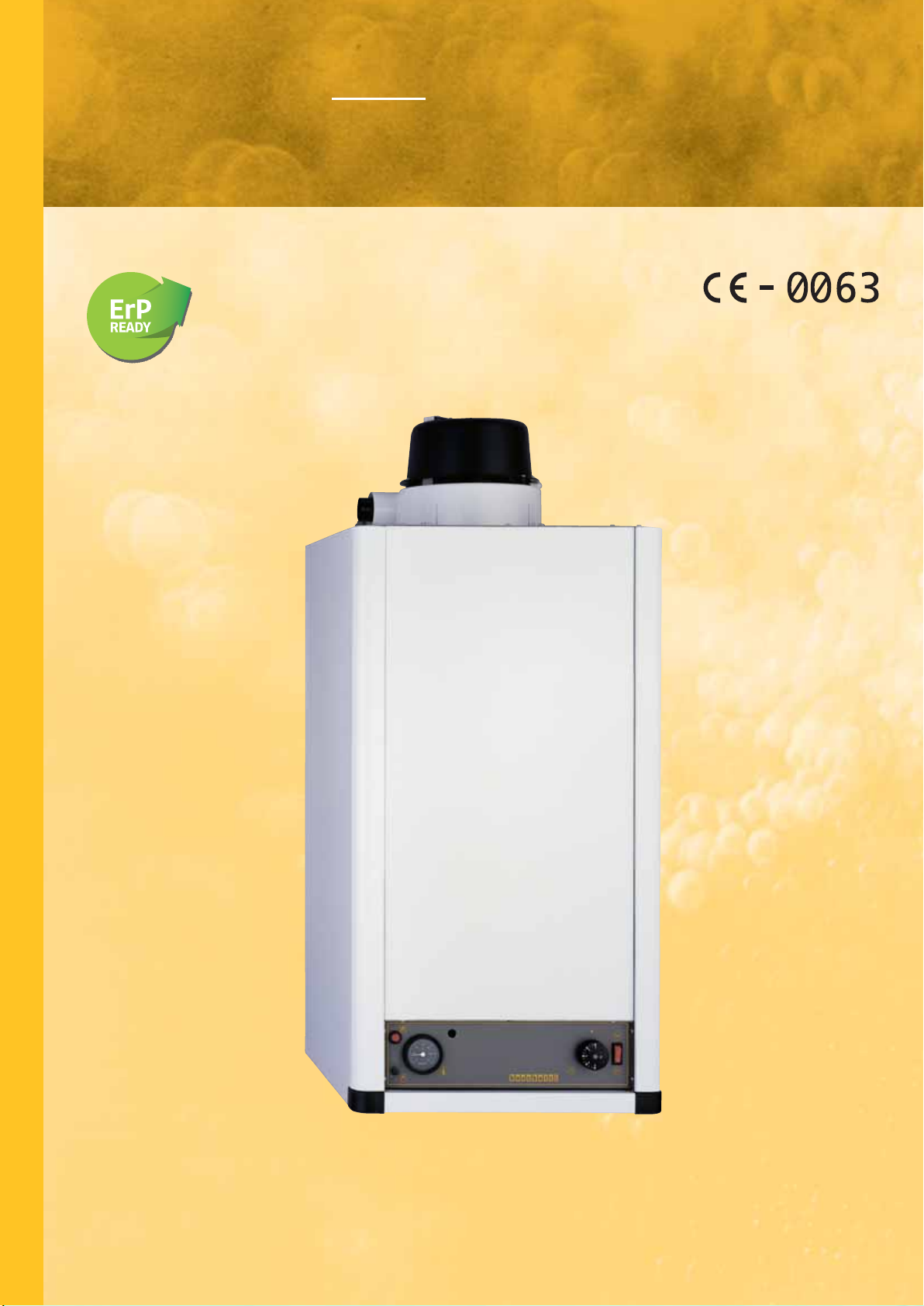
S
C
A
L
D
A
C
Q
Scaldacqua multigas a camera stagna
parete tiraggio forzato.
a
PROOFED CHAMBER MULTIGAS WALL WATER HEATERS WITH FORCED DRAFT.
Modelli/Models BGM/CSTF
U
A
M
U
L
T
I
G
A
S
Page 31
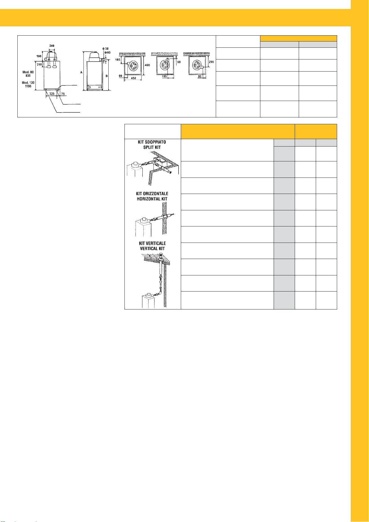
CARATTERISTICHE DEGLI SCALDACQUA - CHARACTERISTICS OF WATER HEATERS
VISTA SUPERIORE
TOP SIGHT
VISTA PO STERIORE
BACK SIGHT
VISTA FRONTALE
FRONTAL SIGHT
Entrata gas 3/8”
Gas entry 3/8”
Acqua calda 1/2”
Hot water 1/2”
Acqua fredda 1/2”
Cold water 1/2”
CARATTERISTICHE DIMENSIONALI - DIMENSIONS DETAILS
Altezza complessiva
Total height (A)
Altezza scarico fumi
Smoke discharge height (B)
Diametro interno scarico fumi
Smoke discharge internal
diameter
Diametro esterno ingresso aria
Air entry external diameter
Diam. flangia per ispezione, pulizia
calcio e sostituz. anodo. Diameter
flange for inspection, cleaning calcium and replacing anode
• Accensione elettronica
Electronic ignition
• Rivelazione di fiamma a ionizzazione
Flame presence
• Boiler internamente vetroporcellanato
POSSIBILITÀ DI SCARICO
DISCHARGE POSSIBILITY
Capacità
Capacity
Portata termica nominale
Nominal thermal capacity
CARATTERISTICHE TECNICHE
TECHNICAL CHARACTERISTICS
Inside glass porcelainized boiler
Potenza resa dell’acqua
• Flangia per ispezione e pulizia calcio
Flange for inspection and cleaning calcium
• Isolamento in poliuretano espanso
Polyurethane foam insulation
•Camera di combustione stagna
Water yield
Unico prelievo a ΔT 25°C (Termost. 70°C - temp.ingres.10°C)
Single drawing ΔT 25°C (Thermostat 70°C - Entry temperature 10°C)
Resa ΔT 45°C
Thermal efficiency ΔT 45°C
Tensione di alimentazione
Feeding voltage
Proofed chamber
Frequenza di alimentazione
• Tiraggio forzato
Forced draft
Feeding frequency
Potenza elettrica totale assorbita
Total electric power absorbed
• Rendimento al 90%
90% Thermal efficiency
• Funzionamento con gas della 2
Working with 2
BGM/CSTF = Boschetti Gas Metano Camera Stagna Tiraggio Forzato
- Su richiesta disponibile Gas Liquido G30-3+ (BGM/CSTF G.P.L.) - On request is available (LPG) liquefied petroleum gas G30-3+ (BGM/CSTF G.P.L.)
LUNGHEZZA MAX DEL DOPPIO TUBO ASPIRAZIONE - SCARICO cm 300 SENZA CAMBIO DI DIREZIONE. A RICHIESTA PUÒ ESSERE FORNITO UN KIT PER
SCARICO SDOPPIATO.
Sicurezza:
- Scaldabagno a gas ad accumulo con camera di combustione a tenuta stagna
rispetto all’ambiente in cui è installato.
- il controllo della combustione, l’accensione e lo spegnimento avvengono per mez-
zo di un pannello elettronico che assicura la massima affidabilità e precisione.
Alto rendimento:
- L’applicazione di un piccolo aspiratore sul condotto dei fumi (assorbimento 14
Watt) ha consentito di poter restringere il passaggio dei fumi, con conseguente
aumento del rendimento che raggiunge condizioni ottimali.
- Nello scaldabagno è stato eliminato il bruciatore pilota con conseguente rispar-
mio di gas, inoltre, essendo a camera stagna si è annullato l’effetto “camino”
ossia quella dannosa circolazione di aria fredda attraverso il tubo di uscita fumi quando il bruciatore è spento
Praticità di installazione:
- Lo scaldabagno essendo a tiraggio forzato, non necessita di canna fumaria.
- Il tubo per il prelievo dell’aria per la combustione e per lo scarico dei gas com-
busti, ha un diametro esterno di soli 60 mm.
- I due tubi concentrici, partono da una calotta superiore che può ruotare di
360°, quindi lo scaldabagno può essere posizionato in un punto qualsiasi a
scelta dell’installatore.
- Funziona con tutti i tipi di miscelatori ed anche con pressioni dell’acqua molto basse.
Componenti e dettagli:
SERBATOIO: robusta lamiera di acciaio vetro porcellanato.
PROTEZIONE CONTRO LE CORROSIONI: anodo al magnesio.
ISOLAMENTO: poliuretano espanso a cellule chiuse di alto spessore.
BRUCIATORE: in acciaio inossidabile AISI 430.
APPARECCHIATURA DI CONTROLLO: pannello elettronico a ionizzazione di fiamma.
Quote e illustrazioni sono indicative. Il costruttore si riserva la facoltà di apportare eventuali modifiche senza alcun preavviso.
nd
and 3rdfamily gas
a
e 3afamiglia
Pressione max acqua
Maximum water pressure
Peso a vuoto
Empty weight
DRAW - DISCHARGE TUBE: MAXIMUM LENGTH WITHOUT DIRECTION CHANGE
300 cm. ON REQUEST IS AVAILABLE A SPLIT DRAIN KIT.
Safety:
- Storage multigas water heater with proofed chamber.
- The switchboard adjusts the combustion check, the ignition and the switching
off of the heater, grant reliability and precision.
High thermal efficiency:
- We get the high thermal efficiency and cutting down of the smoke flue, thanks
to the connection of a small exhaust fan on the smoke flue (electrical absorption 14 Watt).
- Before getting the burner, air warms the water through the tube which links the
firebox with the cap on the top (the tube is into the tank).
- To obtain gas saving, the pilot burner was taken off. When the burner switchs
off there isn’t cold air into the exhaust fire tube.
Easy to install: - The water heater with forced draft hasn’t fire tube.
- The draw – discharge tube is 60 mm outside diameter.
- The concentric tubes are put on the top cap which can 360° turn. The technician can install the heater wherever he wants.
- It works both all kinds of mixers and with low water pressures.
Components and details:
TANK: glass porcelainized steel plate large thickness.
PROTECTION AGAINST CORROSION: magnesium anode.
INSULATION: polyurethane foam large thickness.
BURNER: in stainless steel AISI 430.
CONTROL EQUIPMENT: switchboard with flame electrically-assisted.
Dimensions and pictures are only indicatives. The manufacturer has the right to
make changes without notice.
MODELLO / MODEL
BGM/8Q/CSTF BGM/12Q/CSTF
1040 mm.
895 mm.
38 mm.
60 mm.
85 mm.
U.M.
Kcal/h
Kcal/h
It/hr
volts
bar
litri
Kw
Kw
It
hz
w
Kg
1400 mm.
1255 mm.
38 mm.
60 mm.
85 mm.
MODELLO
MODEL
BGM/8Q/CSTF BGM/12Q/CSTF
75
4300
5,0
4040
4,7
150
85
220-240
50
26
6
49
115
4300
5,0
4040
4,7
231
85
220 - 240
50
26
6
74
S
C
A
L
D
A
C
Q
U
A
M
U
L
T
I
G
A
S
29
Page 32
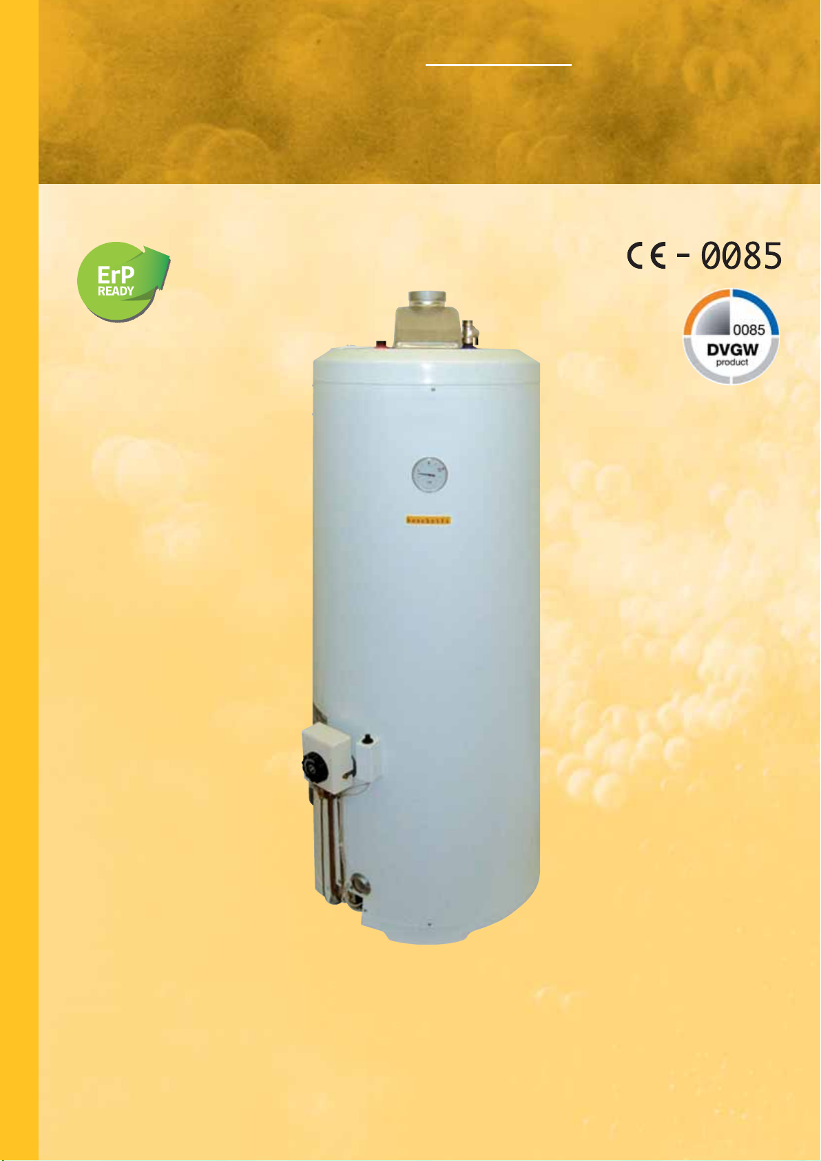
S
C
A
L
D
A
C
Q
Scaldacqua multigas con basamento uso domestico.
S
TORAGE MULTIGAS WATER HEATERS WITH BASE FOR DOMESTIC USE.
Modelli/Models BGM/BD
U
A
M
U
L
T
I
G
A
S
PROGETTATO CON BASSO COEFFICIENTE DI DISPERSIONE DI CALORE E ALTO RENDIMENTO CON
EVAPORAZIONE CONDENSA SECONDO DIN EN 89
EQUIPMENT DESIGNED WITH LOW THERMAL TRANSMITTANCE, HIGH THERMAL EFFICIENCY AND
MOISTURE’S EVAPORATION IN ACCORDING TO THE RULE DIN EN 89
Page 33
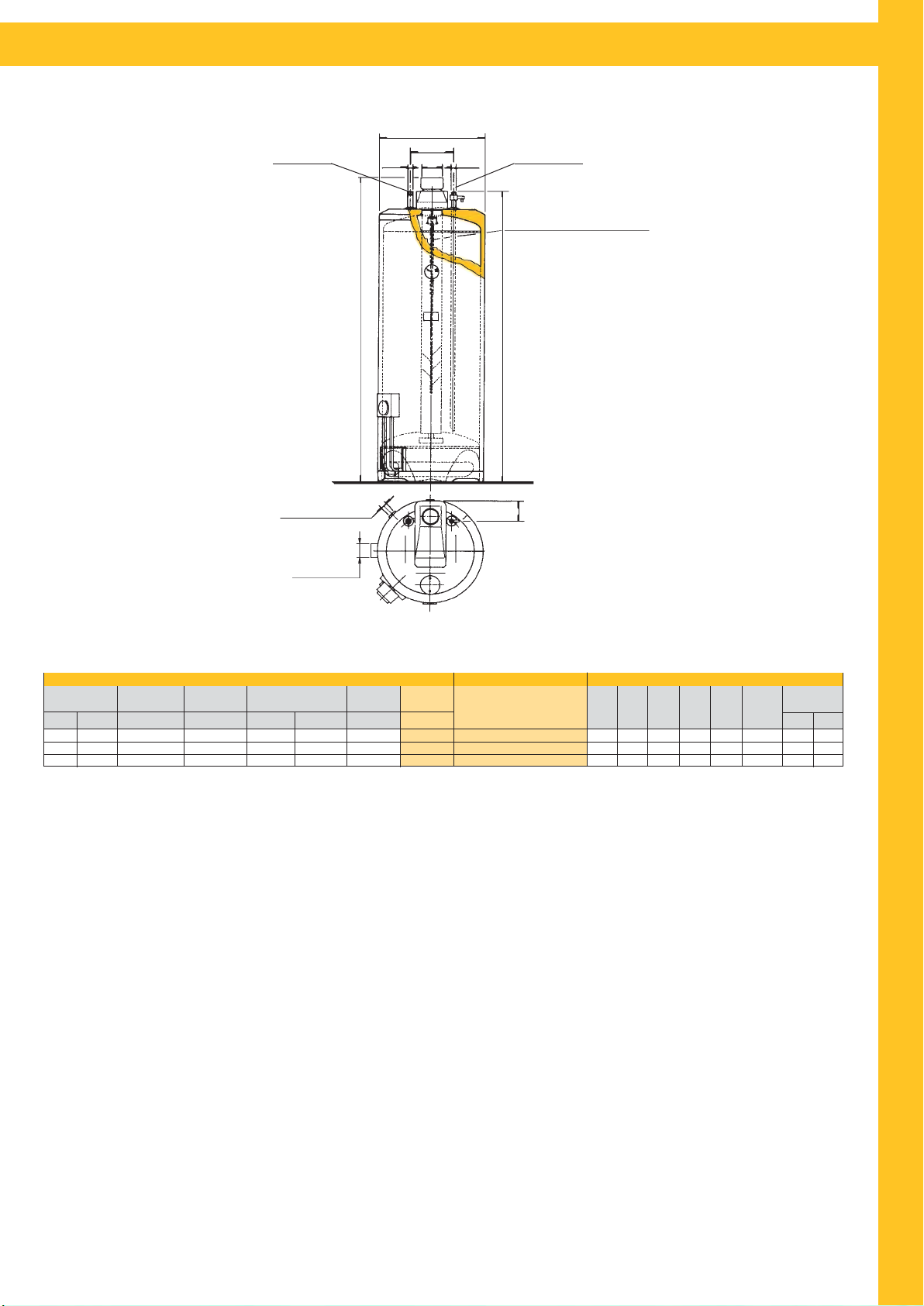
CARATTERISTICHE DEGLI SCALDACQUA - CHARACTERISTICS OF WATER HEATERS
Uscita H2O
Hot water exit
Ricircolo 3/4”
Recirculation 3/4”
Scarico 1”
Water drain 1”
Ø1
D
i
DF
Ø2
Entrata H2O
Cold water entry
Anodi in lega di magnesio AZ63
Magnesium anodes AZ63
S
C
H
i
h
A
L
D
A
C
F
Q
U
A
CARATTERISTICHE/CHARACTERISTICS MODELLO/MODEL DIMENSIONI/DIMENSIONS
Portata termica
Thermal capacity
Kw
8,2
8,2
8,2
** Temperatura acqua in entrata 15°C.
*** Termostato a 70°C. Temperatura ingresso 15°C.
- Su richiesta disponibile Gas Liquido G30-3+ (BGM/BD G.P.L.).
BGM/BD = Boschetti Gas Metano Basamento Domestico
1) Il serbatoio in lamiera di grosso spessore è collaudato a 9 bar e garantito per
pressioni di esercizio di 6 bar. L’attenta esecuzione dei semilavorati e l’esclusiva tecnica di assemblaggio garantiscono una perfetta applicazione delle resine
protettive (vetro porcellanatura).
2) La camera di combustione con un deflettore fumi in acciaio inox, è ampia e
dimensionata per ridurre al minimo la condensa e mantenere a lungo un alto rendimento.
3) L’impianto del gas, è proporzionato alla potenza ed è formato da elementi di
qualità. La valvola omologata è composta da una interruzione gas controllata da
un termostato sensibile alla temperatura dell’acqua e da un’altra interruzione
gas che rimane aperta solamente se il bruciatore pilota è acceso (sicurezza). Il
bruciatore multigas, in acciaio inox, ha un alto rendimento di combustione.
4) Coibentazioni. Vengono eseguite con isolanti con basso coefficiente di disper-
sione di calore e grosso spessore.
5) L’esterno in lamiera, curato nell’estetica e nella lavorazione, è ricoperto da resine bianche applicate e cotte a forno a 220°C dopo un adeguato pretrattamen-
to.
Unico Prelievo
Single Drawing
Kcal/h ***Lt
7000
7000
7000
40°C
230
300
380
Resa ΔT45°C
Yield ΔT45°C
**Lt/h
132
132
132
Consumo
Consumption
Metano
3
m
/h
0,87
0,87
0,87
GPL
kg/h
0,65
0,65
0,65
Peso
Weight
Kg. Lt.
49
65
78
Capacità
Capacity
115
150
190
** Entry water temperature 15°C.
*** Thermostat 70°C. Entry water temperature 15°C.
- On request is available (L.P.G.) Liquefied Petroleum Gas G30-3+ (BGM/BD G.P.L.).
1) The tank is made in steel plate with a large thickness and tested to 9 bar for
working pressure of 6 bar. The careful execution of the unfinished products and
the exclusive assembling technique allow a perfect application of protecting
resins (glass porcelainization).
2) The firebox with a stainless steel smoke deflector, has a big surface to reduce
moisture to a minimum and to keep high thermal efficiency for a long time.
3) The gas plant best quality, is adequate to the power of the heater. The ho-
mologated valve has two units which can stop the gas flow: the first one is controlled by a thermostat water temperature sensitive; the second one works when
the pilot burner is on (safety). The stainless steel multigas burner has high thermal efficiency.
4) The insulations are made with insulating large thickness, with low thermal
transmittance.
5) The external covering is made in steel plate coated with white resins applied
and 220°C furnace cooked after adequate pre-treatment.
Funzionante Gas metano G20-2H
Funzionante Gas liquido G30-3+
Natural Gas G20-2H working
L.P.G. G30-3+ working
BGM/11Q/BD
BGM/15Q/BD
BGM/20Q/BD
D
mm
490
490
490
Hmmhi
1150
1400
1650
mm
1105
1355
1605
mm
200
200
200
M
U
Attacchi
DF
mm
80
80
80
Connections
Ø2
Ø1
3/4”
3/4”
3/4”
3/4”
3/4”
3/4”
L
T
F
i
mm
106
106
106
I
G
A
S
Quote e illustrazioni sono indicative. Il costruttore si riserva la facoltà di apportare eventuali modifiche senza alcun preavviso.
Dimensions and pictures are only indicatives. The manufacturer has the right to
make changes without notice.
31
Page 34
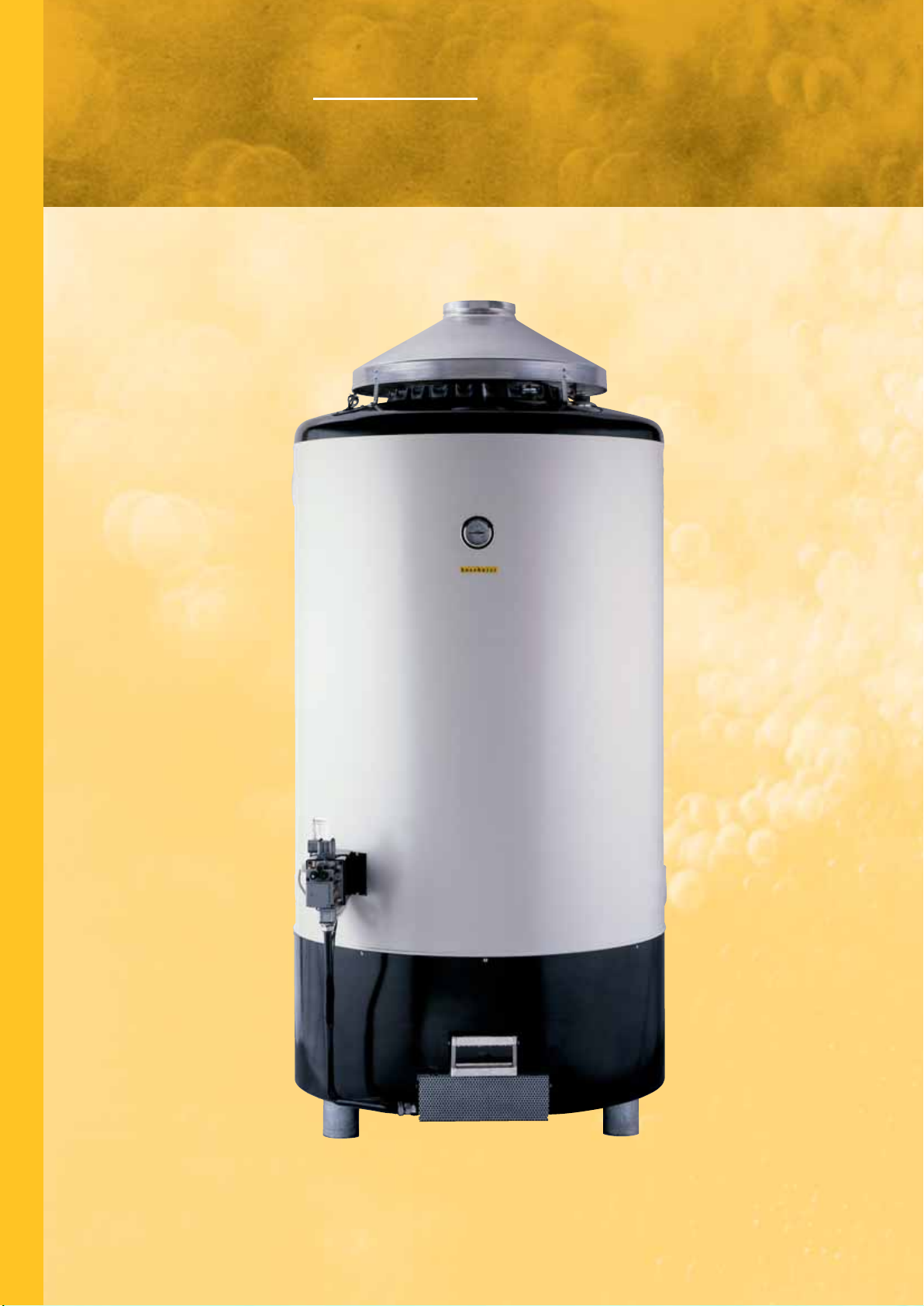
Scaldacqua multigas ad accumulo
S
C
A
L
D
A
C
Q
U
con
basamento uso industriale.
STORAGE MULTIGAS WATER HEATERS WITH BASE FOR INDUSTRIAL USE.
Modelli/Models BGM/BI • BGMT/BI
A
M
U
L
T
I
G
A
S
Page 35
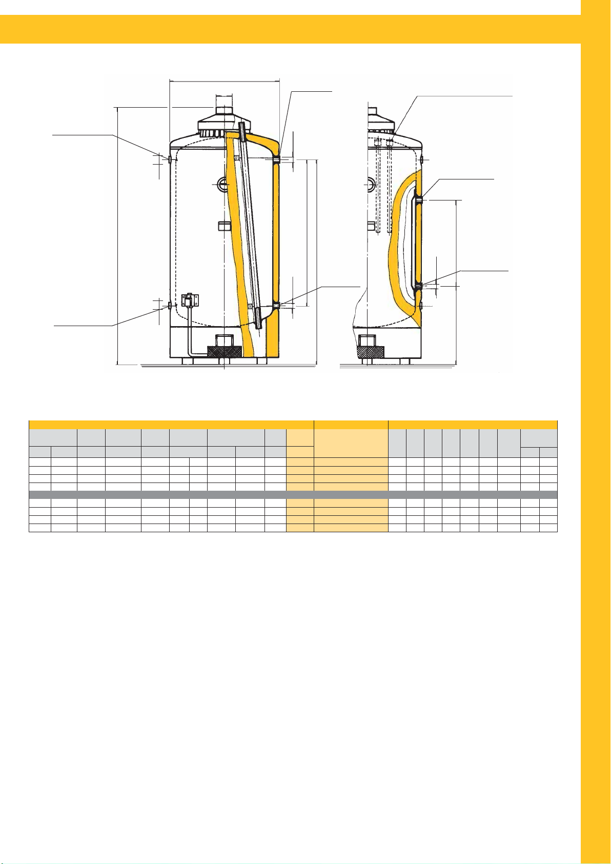
CARATTERISTICHE DEGLI SCALDACQUA - CHARACTERISTICS OF WATER HEATERS
Ricircolo
Recirculation
Entrata H2O
Cold water entry
D
DF
Ø1
Uscita H2O
Hot water exit
Ø1
Anodi in lega di magnesio AZ63
Magnesium anodes AZ63
Mandata Termo
Thermo water entry
S
C
A
H
Ø1
i
h1
Scarico
Water drain
Ø2
1
i
Ritorno Termo
Thermo water exit
L
D
A
C
Ø1
h2
Q
U
APPARECCHI DESTINATI SPECIFICATAMENTE AD ESSERE UTILIZZATI IN PROCESSI INDUSTRIALI IN STABILIMENTI INDUSTRIALI
WATER HEATERS SUITABLE ONLY FOR INDUSTRIAL USES
Portata termica
Thermal capacity
Kw/h
47,4
53,3
80
80
47,4
53,3
80
80
* Fluido riscaldante termo 80°C.
** Temperatura in entrata 15°C.
*** Termostato a 70°C. Temperatura ingresso 15°C.
- Su richiesta disponibile Gas Liquido G30-3+ (BGM/BI G.P.L.).
- Valvola di sicurezza H2O non è a corredo.
BGM/BI = Boschetti Gas Metano Basamento Industriale
BGMT/BI = Boschetti Gas Metano Termo Basamento Industriale
Unico Prelievo
Single Drawing
Kcal/h ***Lt
40800
45900
68850
68850
40800
45900
68850
68850
Lo scaldacqua è stato progettato ed è costruito per le grandi esigenze di acqua
calda, particolarmente adatto negli utilizzi industriali.
1) Il serbatoio in lamiera di grosso spessore è collaudato a 9 bar e garantito per
pressioni di 6 bar. È protetto da un bagno di zinco ed anodi al magnesio (350 gr.
2
di superficie).
per m
2) Nella versione termo lo scambiatore, di ampia superficie, è ad intercapedine
con gli attacchi bilaterali.
3) La camera di combustione è ampia (da 22 a 26 tubi fumo) e dimensionata
per ridurre al minimo la condensa e mantenere a lungo un alto rendimento.
4) L’impianto del gas, è proporzionato alla potenza ed è formato da elementi di
qualità. La valvola omologata è composta da una interruzione gas controllata da
un termostato sensibile alla temperatura dell’acqua e da un’altra interruzione
gas che rimane aperta solamente se il bruciatore pilota è acceso (sicurezza). I
bruciatori multigas, in acciaio inox, hanno un alto rendimento di combustione. La
valvola gas e l’accensione funzionano elettricamente.
5) La coibentazione è di grosso spessore e ad alta densità per un lungo mantenimento della temperatura.
6) L’esterno, in lamiera, è particolarmente robusto e ricoperto da resine bianche
applicate e cotte a forno a 220°C.
Quote e illustrazioni sono indicative. Il costruttore si riserva la facoltà di apportare eventuali modifiche senza alcun preavviso.
CARATTERISTICHE/CHARACTERISTICS MODELLO/MODEL DIMENSIONI/DIMENSIONS
Resa ΔT45°C
Yield ΔT45°C
40°C
1600
2000
3000
4000
1600
2000
3000
4000
**Lt/h
770
867
1300
1300
770
867
1300
1300
Focolare
Furnace
Superficie
Surface m
4,5
5,5
7,2
7,8
4,5
5,5
7,2
7,8
Consumo
Consumption
Metano
GPL
2
m3/h
kg/h
3,7
5
4,2
5,6
6,3
8,4
6,3
8,4
3,7
5
4,2
5,6
6,3
8,4
6,3
8,4
Peso
Scambiatore termo*
Heat Exchanger*
Resa/Yield
Superficie
2
ΔT 45°C-Lt/h
Surface m
VERSIONE TERMO BILATERALE/BILATERAL THERMO VERSION
2
2,65
3,3
4,9
533
706
880
1306
Weight
Kg. Lt.
390
460
637
750
460
552
788
980
Capacità
Funzionante Gas metano G20-2H
Capacity
Funzionante Gas liquido G30-3+
Natural Gas G20-2H working
800
1000
1500
2000
800
1000
1500
2000
L.P.G. G30-3+ working
BGM/800/BI
BGM/1000/BI
BGM/1500/BI
BGM/2000/BI
BGMT/800/BI
BGMT/1000/BI
BGMT/1500/BI
BGMT/2000/BI
* Heated fluid 80°C.
** Entry water temperature 15°C.
*** Thermostat 70°C. Entry water temperature 15°C.
- On request is available (L.P.G.) Liquefied Petroleum Gas G30-3+ (BGM/BI G.P.L.).
- H2O safety valve isn’t included.
DmmHmmh1
2075
960
2405
960
2445
1210
2960
1210
2075
960
2405
960
2445
1210
2960
1210
mm
1600
1950
1935
2435
1600
1950
1935
2435
h
mm
745
745
780
780
2
The storage multigas water heater with base for industrial use has been designed to satisfy hot water needs. It is suitable for industrial use.
1) The tank is made in steel plate with a large thickness and tested to 9 bar for
working pressure of 6 bar. It is galvanized and protected by magnesium anodes
(350 gr./m
2
of surface).
2) In thermo version, the heat exchanger with a big surface, has hollow space
and bilateral thermo connections.
3) The firebox has a big surface (from 22 to 26 fire tubes), to reduce moisture
to a minimum and to keep high thermal efficiency for a long time.
4) The gas plant best quality, is adequate to the power of the heater. The ho-
mologated valve has two units which can stop the gas flow: the first one is controlled by a thermostat water temperature sensitive; the second one works when
the pilot burner is on (safety). The stainless steel multigas burners have high
thermal efficiency. The gas valve and the ignition work electrically.
5) The insulation has large thickness and high density to keep the temperature
for a long time.
6) The solid external covering is made in steel plate, coated with white resins
applied and 220°C furnace cooked.
Dimensions and pictures are only indicatives. The manufacturer has the right to
make changes without notice.
i
mm
1020
1370
1320
1820
1020
1370
1320
1820
i1
mm
600
900
900
1400
DF
mm
180
180
180
180
180
180
180
180
Attacchi
Connections
Ø1
Ø2
2”
2”
2”1/2
2”1/2
2”
2”
2”
2”
2”
2”1/2
2”
2”1/2
33
A
M
U
L
T
I
G
A
S
Page 36
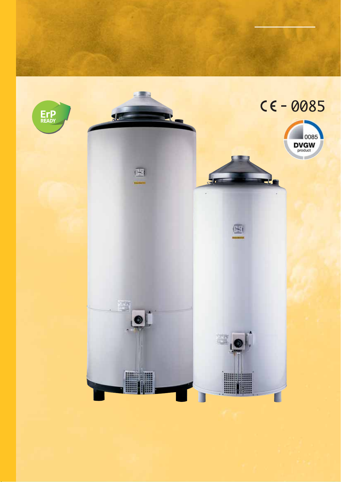
S
C
A
L
D
A
C
Q
Scaldacqua multigas ad accumulo con basamento
uso commerciale.
STORAGE MULTIGAS WATER HEATERS WITH BASE FOR COMMERCIAL USE.
Modelli/Models BGM/BA • BGM/T/BA
U
A
M
U
L
T
I
G
A
S
PROGETTATO CON BASSO COEFFICIENTE DI DISPERSIONE DI CALORE E ALTO RENDIMENTO CON
EVAPORAZIONE CONDENSA SECONDO DIN EN 89
EQUIPMENT DESIGNED WITH LOW THERMAL TRANSMITTANCE, HIGH THERMAL EFFICIENCY AND
MOISTURE’S EVAPORATION IN ACCORDING TO THE RULE DIN EN 89
Page 37
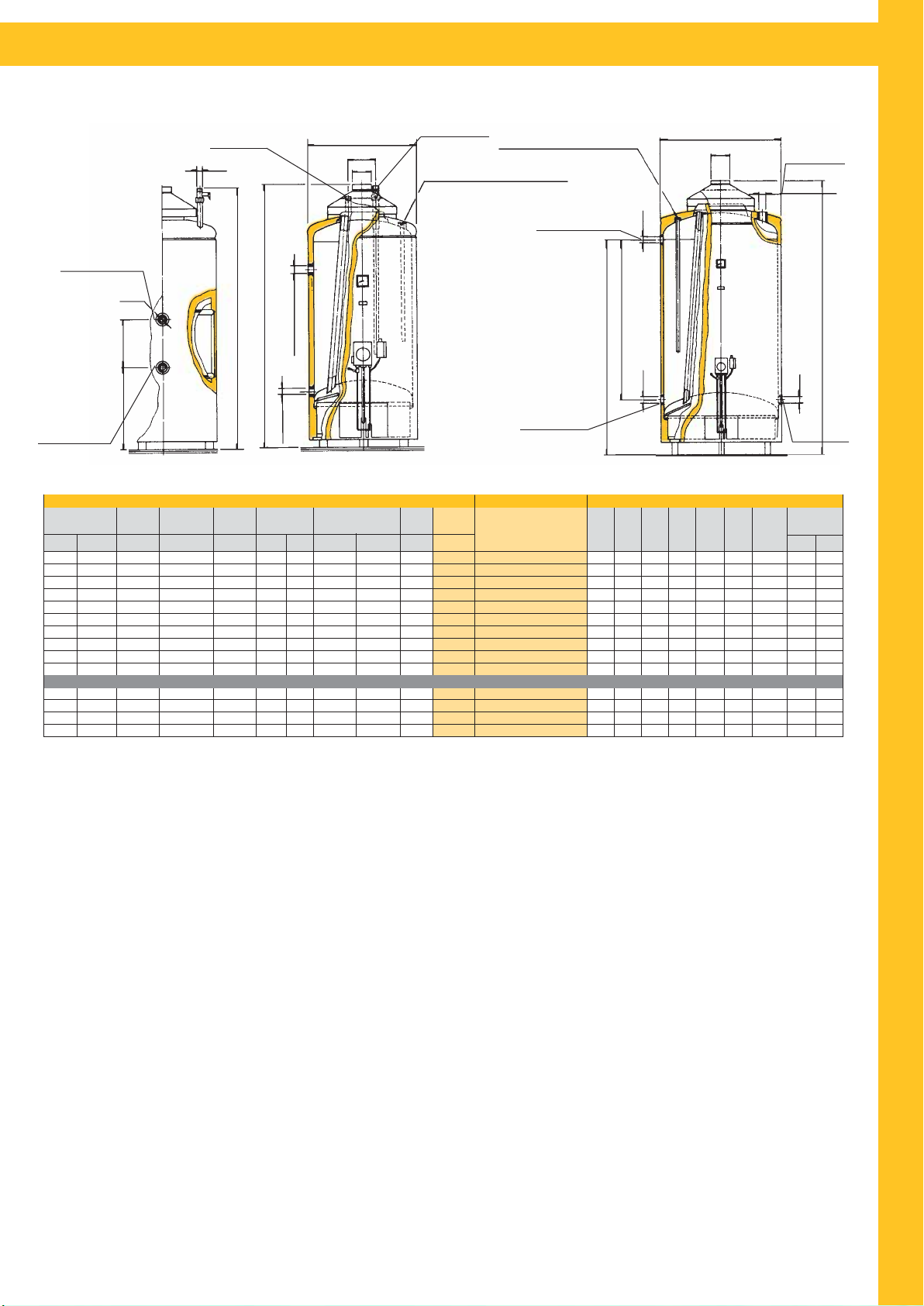
CARATTERISTICHE DEGLI SCALDACQUA - CHARACTERISTICS OF WATER HEATERS
BGM 15Q - 60Q/BA BGM 80Q - 200Q/BA
Uscita H2O
Hot water exit
Ø1
Mandata Termo
Thermo water entry
Ø2
H
h1
i1
2
h
Ritorno Termo
Thermo water exit
CARATTERISTICHE/CHARACTERISTICS MODELLO/MODEL DIMENSIONI/DIMENSIONS
40°C
***Lt
300
400
600
800
940
1180
1510
1900
2800
3800
400
600
940
1180
Resa ΔT45°C
Yield ΔT45°C
**Lt/h
226
226
380
380
477
477
555
555
555
555
226
380
477
477
Focolare
Furnace
Superficie
Surface m
0,82
1,1
1,7
2,2
2,3
2,8
3,3
3,3
3,3
3,3
1,1
1,7
2,3
2,8
2O non è a corredo.
Kcal/h
12000
12000
20000
20000
25000
25000
29000
29000
29000
29000
12000
20000
25000
25000
Unico Prelievo
Single Drawing
Portata termica
Thermal capacity
Kw
14
14
23,2
23,2
29,5
29,5
34
34
34
34
14
23,2
29,5
29,5
* Fluido riscaldante termo 80°C.
** Temperatura in entrata 15°C.
*** Termostato a 70°C. Temperatura ingresso 15°C.
• Per questi modelli la valvola di sicurezza H
- Su richiesta disponibile Gas Liquido G30-3+ (BGM/BA G.P.L.).
BGM/BA = Boschetti Gas Metano Basamento Aperto
BGM/T/BA = Boschetti Gas Metano Termo Basamento Aperto
Ricircolo 3/4”
Scarico
Water drain
Consumo
Consumption
Metano
2
3
m
/h
1,48
1,48
2,45
2,45
3,12
3,12
3,6
3,6
3,6
3,6
1,48
2,45
3,12
3,12
Entrata H2O
D
i
DF
Recirculation 3/4”
Scambiatore termo*
Heat Exchanger*
GPL
kg/h
1,10
1,10
1,83
1,83
2,32
2,32
2,68
2,68
2,68
2,68
VERSIONE TERMO BILATERALE/BILATERAL THERMO VERSION
1,10
1,83
2,32
2,32
Superficie
Surface m
0,77
1,11
2,03
2,25
Resa/Yield
2
ΔT 45°C-Lt/h
205
296
541
600
Cold water entry
Anodi in lega di magnesio AZ63
Magnesium anodes AZ63
Peso
Capacità
Funzionante Gas metano G20-2H
Weight
Kg. Lt.
86
98
137
167
208
237
307
353
489
550
112
157
244
277
Capacity
Funzionante Gas liquido G30-3+
Natural Gas G20-2H working
150
200
300
400
470
590
755
950
1400
1900
200
300
470
590
* Heated fluid 80°C.
** Entry water temperature 15°C.
*** Thermostat 70°C. Entry water temperature 15°C.
• For these models H
- On request is available (L.P.G.) Liquefied Petroleum Gas G30-3+ (BGM/BA G.P.L.).
Anodi in lega di magnesio AZ63
Magnesium anodes AZ63
Ricircolo
Recirculation
Entrata H2O
Cold water entry
L.P.G. G30-3+ working
BGM15Q/BA
BGM20Q/BA
BGM30Q/BA
BGM40Q/BA
BGM50Q/BA
BGM60Q/BA
BGM80Q/BA•
BGM100Q/BA•
BGM150Q/BA•
BGM200Q/BA•
BGM/T/20Q/BA
BGM/T/30Q/BA
BGM/T/50Q/BA
BGM/T/60Q/BA
2O Safety valve isn’t included.
i
h1
DmmHmmh1
1355
550
1600
550
1685
650
2055
660
1920
750
2255
760
2125
910
2490
910
2320
1210
2820
1210
1600
550
1685
650
1920
750
2255
760
Ø1
Ø1
mm
1320
1565
1660
2025
1875
2200
1550
1920
1675
2175
1565
1660
1875
2200
h
mm
420
420
495
495
D
DF
Uscita H2O
Hot water exit
Manicotto 2”
Sleeve 2”
S
C
H
A
L
Ø1
D
Scarico
Water drain
A
C
Q
U
A
M
U
L
T
i
2
mm
140
140
140
140
140
140
1145
1515
1260
1760
140
140
140
140
i1
mm
390
490
790
890
DF
mm
100
100
120
120
140
140
140
140
140
140
100
120
140
140
Attacchi
Connections
Ø1
Ø2
3/4”
3/4”
1”
1”
1”
1”
2”
2”
2”1/2
2”1/2
1”
3/4”
1”
1”
1”
1”
1”
1”
I
G
A
Lo scaldacqua è stato progettato ed è costruito per le grandi esigenze di acqua
calda, particolarmente adatto negli utilizzi industriali, condominiali, nelle comunità e in abitazioni con più servizi.
1) Il serbatoio è collaudato a 9 bar e garantito per pressioni di 6 bar. È’ vetro
porcellanato per modelli 15Q - 20Q - 30Q - 40Q - 50Q - 60Q, e zincato a caldo
corredato di anodo al magnesio (350 gr. per m2di superficie) per modelli 80Q 100Q - 150Q - 200Q.
2) Nella versione termo lo scambiatore, di ampia superficie, è ad intercapedine
con gli attacchi bilaterali.
3) La camera di combustione è ampia (da 6 a 12 tubi fumo) e dimensionata per
ridurre al minimo la condensa e mantenere a lungo un alto rendimento.
4) L’impianto del gas, è proporzionato alla potenza ed è formato da elementi di
qualità. La valvola omologata è composta da una interruzione gas controllata da
un termostato sensibile alla temperatura dell’acqua e da un’altra interruzione
gas che rimane aperta solamente se il bruciatore pilota è acceso (sicurezza). Il
bruciatore multigas, in acciaio inox, ha un alto rendimento di combustione.
5) La coibentazione è di grosso spessore e ad alta densità per un lungo mantenimento della temperatura.
6) L’esterno, in lamiera, è particolarmente robusto e ricoperto da resine bianche
applicate e cotte a forno a 220°C.
Quote e illustrazioni sono indicative. Il costruttore si riserva la facoltà di apportare eventuali modifiche senza alcun preavviso.
The storage multigas water heater with base for commercial use has been designed to satisfy hot water needs. It is suitable for industrial use, condominium,
community and for houses with more bathrooms.
1) The tank is tested to 9 bar for working pressure of 6 bar. It is glass porcelainized for models 15Q - 20Q - 30Q - 40Q - 50Q - 60Q, and hot-galvanized with
magnesium anode (350 gr./m2of surface) for models 80Q - 100Q - 150Q - 200Q.
2) In thermo version, the heat exchanger with a big surface, has hollow space
and bilateral thermo connections.
3) The firebox has a big surface (from 6 to 12 fire tubes), to reduce moisture to
a minimum and to keep high thermal efficiency for a long time.
4) The gas plant best quality, is adequate to the power of the heater. The ho-
mologated valve has two units which can stop the gas flow: the first one is controlled by a thermostat water temperature sensitive; the second one works when
the pilot burner is on (safety). The stainless steel multigas burner has high thermal efficiency.
5) The insulation has large thickness and high density to keep the temperature
for a long time.
6) The solid external covering is made in steel plate, coated with white resins
applied and 220°C furnace cooked.
Dimensions and pictures are only indicatives. The manufacturer has the right to
make changes without notice.
35
S
Page 38
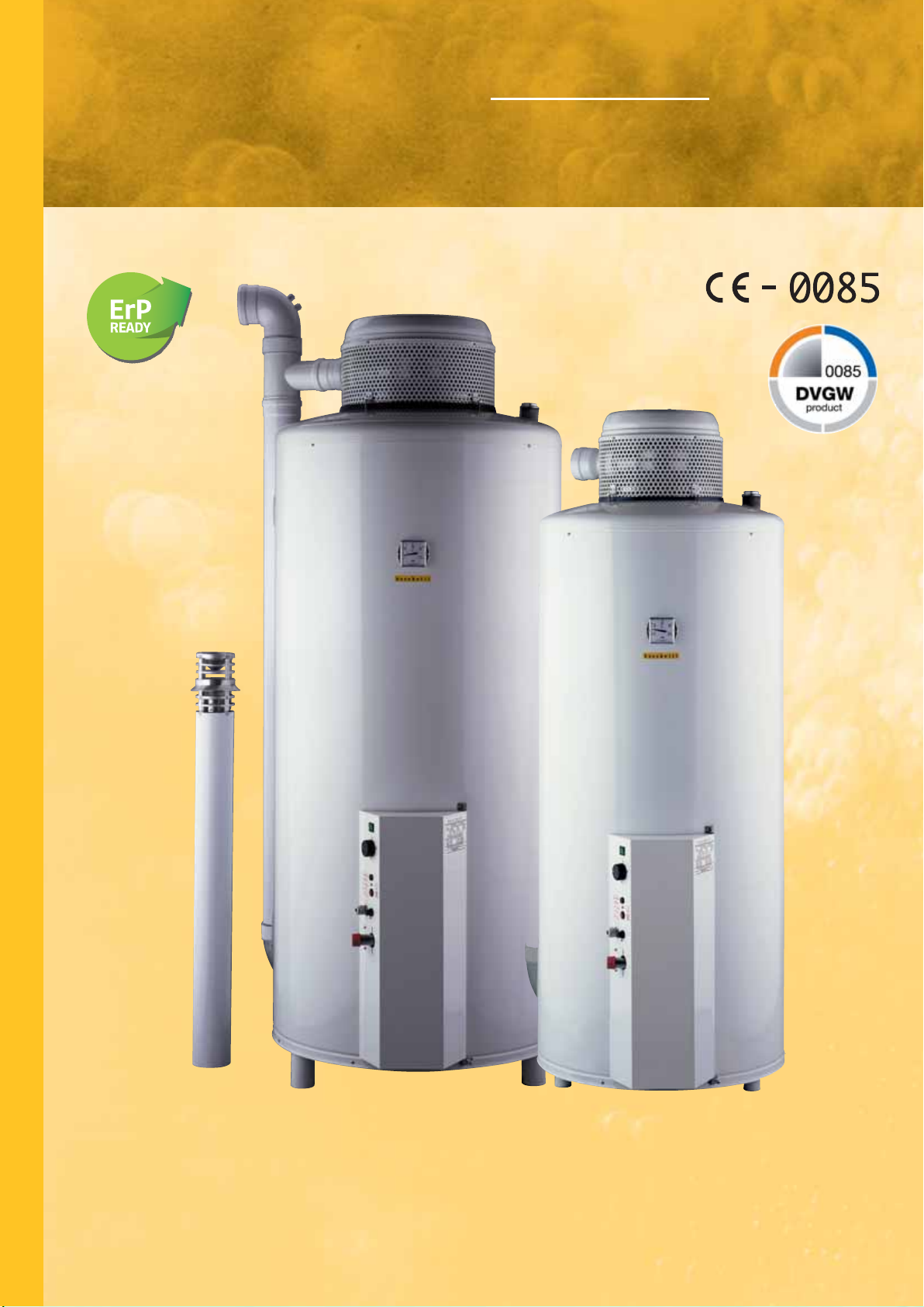
Scaldacqua multigas ad accumulo con basamento
S
C
A
L
D
A
C
Q
U
uso commerciale
camera stagna.
STORAGE MULTIGAS WATER HEATERS WITH BASE FOR
COMMERCIAL USE AIRTIGHT
Modelli/Models BGM/CS • BGM/T/CS
-CHAMBER.
A
M
U
L
T
I
G
A
S
PROGETTATO CON BASSO COEFFICIENTE DI DISPERSIONE DI CALORE E ALTO RENDIMENTO CON
EVAPORAZIONE CONDENSA SECONDO DIN EN 89
EQUIPMENT DESIGNED WITH LOW THERMAL TRANSMITTANCE, HIGH THERMAL EFFICIENCY AND
MOISTURE’S EVAPORATION IN ACCORDING TO THE RULE DIN EN 89
Page 39
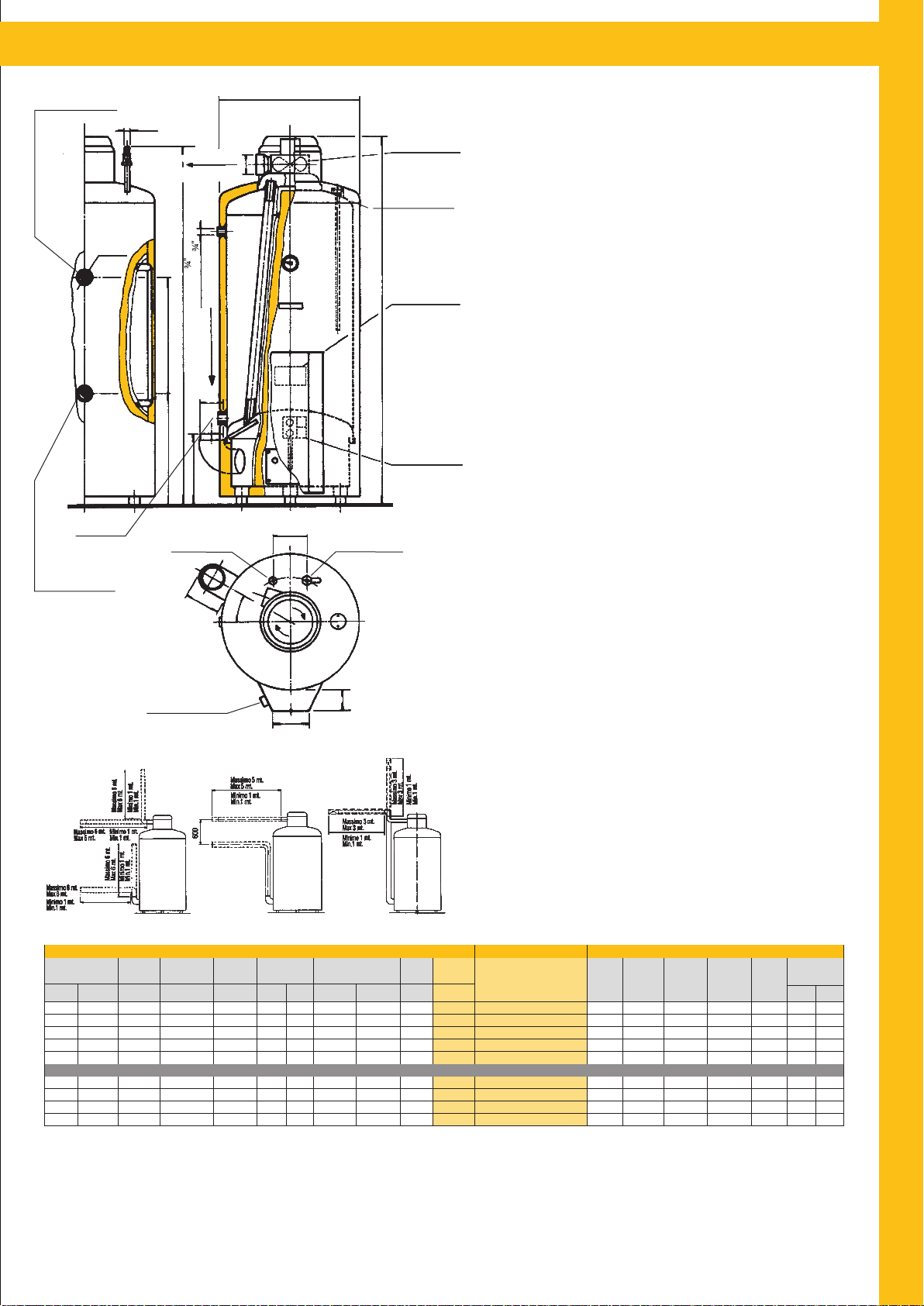
CARATTERISTICHE DEGLI SCALDACQUA - CAMERA STAGNA - CHARACTERISTICS OF WATER HEATERS AIRTIGHT - CHAMBER
Mandata Termo
Thermo water entry
Ø2
Scarico
Water drain
Ø1
Espulsione Fumi
Smokes discharge
h1
i1h2
Uscita H2O
Hot water exit
Ricircolo
300
Recirculation
Aspirazione Aria
Ø100
Air draw
D
Ventola-Espulsione
Fumi-Orientabile
Revolving fan for
smokes discharge
Ø80
Anodo in lega
di magnesio AZ63
Magnesium
anode AZ63
• CAMERA STAGNA
• AIRTIGHT - CHAMBER
• SICUREZZA ALTO RENDIMENTO
• SAFETY HIGH EFFICIENCY
Lo scaldacqua è stato progettato ed è costruito per le grandi esigenze di
acqua calda, particolarmente adatto negli utilizzi industriali, condominiali, nelle comunità e in abitazioni con più servizi.
Centralina elettronica
Trigger box
1) Il serbatoio vetro porcellanato (mod. 20Q - 30Q - 40Q - 50Q - 60Q) e
corredato di anodo al magnesio (350 gr. per m
2
di superficie), è collaudato
a 9 bar e garantito per pressioni di 6 bar.
2) Nella versione termo lo scambiatore, di ampia superficie, è ad interca-
S
C
pedine con gli attacchi bilaterali.
3) La camera di combustione, è ampia e dimensionata per ridurre al
H
minimo la condensa e mantenere a lungo un alto rendimento.
4) L’impianto del gas, è proporzionato alla potenza ed è formato da
elementi di qualità. La valvola omologata è composta da una interruzione gas controllata da un termostato sensibile alla temperatura
dell’acqua e da un’altra interruzione gas che rimane aperta solamente
A
L
D
se il bruciatore è acceso (sicurezza). Il bruciatore multigas, in acciaio
Elettrovalvola Gas
Gas solenoid valve
inox, ha un alto rendimento di combustione.
5) La coibentazione è di grosso spessore e ad alta densità per un lungo
mantenimento della temperatura.
6) L’esterno, in lamiera, è particolarmente robusto e ricoperto da resine
A
C
bianche applicate e cotte a forno a 220°C.
Q
140
2O
Entrata H
Cold water entry
Quote e illustrazioni sono indicative. Il costruttore si riserva la facoltà di
apportare eventuali modifiche senza alcun preavviso.
U
Ritorno Termo
Thermo water exit
LUNGHEZZA MASSIMA E MINIMA DEI CONDOTTI PER PRESA D’ARIA E SCARICO DEI PRODOTTI DI COMBUSTIONE
Portata termica
Thermal capacity
Kw Kcal/h ***Lt
14
23,2
23,2
29,5
29,5
14 12000 400
23,2
29,5
29,5
Maximum and minimum lenght of air drawing pipes and smokes discharge.
Perdite di carico per ogni curva = 1 mt Load loss for each quarter bend = 1 mt
Unico Prelievo
Single Drawing
40°C
12000
400
20000
600
20000
800
940
25000
1180
25000
600
20000
25000
940
25000
1180
130
0°
30°
Quadro di controllo
Switchboard
CARATTERISTICHE/CHARACTERISTICS MODELLO/MODEL DIMENSIONI/DIMENSIONS
Δ
Resa T45°C
Yield T45°C
Δ
**Lt/h
226
378
378
472
472
378
472
472
Focolare
Furnace
Superficie
Surface m
1,1
1,7
2,2
2,3
2,8
1,7
2,3
2,8
150
Consumo
Consumption
Metano
2
3
m
/h
1,48
2,45
2,45
3,12
3,12
2,45
3,12
3,12
80
T 45°C-Lt/h
296
541
600
Peso
Weight
108
145
164
220
252
165
256
292
Scambiatore termo*
Heat Exchanger*
Superficie
Surface m
1,1
2,03
2,25
Resa/Yield
2
Δ
GPL
kg/h
1,10
1,83
1,83
2,32
2,32
VERSIONE TERMO BILATERALE/BILATERAL THERMO VERSION
1,83
2,32
2,32
Capacità
Capacity
Kg. Lt.
200
300
400
470
590
200
300
470
590
The storage multigas water heater with base for commercial use airtightchamber has been designed to satisfy hot water needs. It is suitable for
industrial use, condominium, community and for houses with more
bathrooms.
1) The tank glass porcelainized for models 20Q - 30Q - 40Q - 50Q - 60Q
with magnesium anode (350 gr./m
2
of surface) is tested to 9 bar for
working pressure of 6 bar.
2) In thermo version, the heat exchanger with a big surface, has hollow
space and bilateral thermo connections.
3) The firebox has a big surface to reduce moisture to a minimum and to
keep high thermal efficiency for a long time.
4) The gas plant best quality, is adequate to the power of the heater. The
homologated valve has two units which can stop the gas flow: the first
one is controlled by a thermostat water temperature sensitive; the
second one works when the burner is on (safety). The stainless steel
multigas burner has high thermal efficiency.
5) The insulation has large thickness and high density to keep the
temperature for a long time.
6) The solid external covering is made in steel plate, coated with white
resins applied and 220°C furnace cooked.
Dimensions and pictures are only indicatives. The manufacturer has the
right to make changes without notice.
Funzionante Gas metano G20-2H
Funzionante Gas liquido G30-3+
Natural Gas G20-2H working
L.P.G. G30-3+ working
BGM20Q/CS
BGM30Q/CS
BGM40Q/CS
BGM50Q/CS
BGM60Q/CS
BGM/T/20Q/CS226 1,1 1,48 1,10 0,77 205 122
BGM/T/30Q/CS
BGM/T/50Q/CS
BGM/T/60Q/CS
D
mmHmm
1620
550
1715
650
2085
660
1940
750
2265
760
550 1620
650
1715
750
1940
760
2265
h
1
2
mm
1490
1585
1955
1805
2130
1490
1585
1805
2130
h
mm
410 390 3/4” 1”
425
495
495
i
mm
490
790
890
1
Attacchi
Connections
Ø1
3/4”
1”
1”
1”
1”
1”
1”
1”
Ø2
A
M
U
L
T
I
G
A
S
1”
1”
1”
* Fluido riscaldante termo 80°C.
** Temperatura in entrata 15°C.
*** Termostato a 70°C. Temperatura ingresso 15°C.
- Su richiesta disponibile Gas Liquido G30-3+ (BGM/CS G.P.L.).
BGM/CS = Boschetti Gas Metano Camera Stagna
BGM/T/CS = Boschetti Gas Metano Termo Camera Stagna
* Heated fluid 80°C.
** Entry water temperature 15°C.
*** Thermostat 70°C. Entry water temperature 15°C.
- On request is available (L.P.G.) Liquefied Petroleum Gas G30-3+ (BGM/CS G.P.L.).
37
Page 40
Scaldacqua - Storage multigas water heathers
Scaldacqua
multigas
ad accumulo
a parete.
TORAGE MULTIGAS
S
WATER
WALL
HEATERS.
pag. 26
Scaldacqua
multigas
a camera stagna
a parete
tiraggio forzato.
ROOFER CHAMBER
P
WALL WATER
MULTIGAS
HEATERS
FORCED
WITH
DRAFT.
pag. 28
Scaldacqua
multigas
con basamento
uso domestico.
TORAGE MULTIGAS
S
HEATERS
WATER
BASE
WITH
DOMESTIC USE.
FOR
pag. 30
Scaldacqua
multigas
ad accumulo
con basamento
uso industriale.
TORAGE MULTIGAS
S
HEATERS
WATER
BASE
WITH
INDUSTRIAL USE.
FOR
pag. 32
Scaldacqua
multigas
ad accumulo
con basamento
uso commerciale.
TORAGE MULTIGAS
S
HEATERS
WATER
BASE
WITH
COMMERCIAL USE.
FOR
pag. 34
Scaldacqua
ad accumulo
con basamento
uso commerciale
camera stagna.
STORAGE MULTIGAS
WATER
COMMERCIAL USE
FOR
AIRTIGHT
BOSCHETTI INDUSTRIE MECCANICHE s.r.l.
www.boschettindustriemeccaniche.it
vendite@boschettindustriemeccaniche.it
multigas
HEATERS
BASE
WITH
-CHAMBER.
pag. 36
 Loading...