

Bosch Benchmark HSLP751UC Installation Manual
Built-In Oven
Installation Manual
500/800/BenchmarkTM Series
HBL53, HBL54, HBL55, HBL56, HBL57,
HBL84, HBL86, HBL87, HBN54, HBN56,
HBN84, HBN86, HBLP45, HBLP65,
HBLP75, HSLP75

Table of Contents
Questions?
1-800-944-2904
www.bosch-home.com/us
We look forward to hearing from you!
This Bosch Appliance is made by
BSH Home Appliances Corporation
1901 Main Street, Suite 600
Irvine, CA 92614
Safety Definitions . . . . . . . . . . . . . . . 1
Preparation . . . . . . . . . . . . . . . . . . . . 3
Before You Begin . . . . . . . . . . . . . . . . . . . . . 3
Tools and Parts Needed . . . . . . . . . . . . . . . . 3
Parts Included . . . . . . . . . . . . . . . . . . . . . . . . 3
General Information . . . . . . . . . . . . . . . . . . . . 3
Dimensions and Cabinet
Requirements . . . . . . . . . . . . . . . . . . 4
Removing Packaging . . . . . . . . . . . . 4
Preparing Oven . . . . . . . . . . . . . . . . . . . . . . . 4
Installation . . . . . . . . . . . . . . . . . . . . . 5
Determine the Installation Type . . . . . . . . . . . 5
Pre-Assembly of Combination Ovens Prior to
Installation . . . . . . . . . . . . . . . . . . . . . . . . . . . 5
Combination Oven Installation . . . . . . . . . . . . 5
Electrical Installation . . . . . . . . . . . . . . . . . . . 8
Installing the Oven Unit into the Wall
Cabinet . . . . . . . . . . . . . . . . . . . . . . . . . . . . . 9
For Best Installation . . . . . . . . . . . . . . . . . . . . 9
Correct Inside Oven Lift Point . . . . . . . . . . . . 9
Installing the Oven . . . . . . . . . . . . . . . . . . . . 11
Bottom Hinge Doors Only - Remove Prior to
Install . . . . . . . . . . . . . . . . . . . . . . . . . . . . . . 11
Installing the Oven into the
Cabinet (all ovens) . . . . . . . . . . . . . . . . . . . . 12
Ovens with Bottom Hinge Doors Only . . . . . 13
Ovens with Side Hinge Doors Only . . . . . . . 13
Before Calling Service . . . . . . . . . . . . . . . . . 16
Cabinet Dimension Requirements . 18
Dimensions for 27” Single Oven Units . . 18
Single Oven 27” Traditional Installation,
Cabinet and Undercounter . . . . . . . . . . . . . . 18
Single Oven 27” Flush Mount Installation . . 18
Dimensions for 27” Double Oven Units . . 18
Double Oven 27” Traditional Installation . . . 18
Double Oven 27” Flush Mount Installation . . 19
Dimensions for 30” Single Oven Units . . 19
Single Oven 30” Traditional Installation,
Cabinet and Undercounter . . . . . . . . . . . . . . 19
Single Oven 30” Flush Mount Installations . 19
Dimensions for 30” Double Oven Units . . 20
Double Oven 30” Traditional Installation . . . 20
Double Oven 30” Flush Mount Installion . . . 20
Dimensions for 30” Combination Oven
and Microwave or Steam Oven Units . . . . 21
Combination Oven and Microwave or Steam
Oven 30” Traditional Installation . . . . . . . . . 21

9 IMPORTANT SAFETY INSTRUCTIONS
READ AND SAVE THESE INSTRUCTIONS
Safety Codes and Standards
Safety Definitions
This appliance complies with one or more of the following
Standards:
9 WARNING
This indicates that death or serious injuries may
occur as a result of non-observance of this warning.
9 CAUTION
This indicates that minor or moderate injuries may
occur as a result of non-observance of this warning.
• UL 858, Household Electric Ranges
• UL 923, Microwave Cooking Appliances
• UL 507, The Standard for the Safety of Electric Fans
• CAN/CSA-C22.2 No. 113-M1984 Fans and Ventilators
It is the responsibility of the owner and the installer to
determine if additional requirements and/or standards
apply to specific installations.
NOTICE: Ths indicates that damage to the appliance or
property may occur as a result of non-compliance with this
advisory.
Note: This alerts you to important information and/or tips.
WARNING:
If the information in this manual is not followed exactly, fire
or shock may result causing property damage or personal
injury.
WARNING:
Do not repair or replace any part of the appliance unless
specifically recommended in the manuals. Improper
installation, service or maintenance can cause injury or
property damage. Refer to this manual for guidance. All
servicing should be done by a qualified technician.
Appliance Handling Safety
Do not lift appliance by door handle. Remove the door for
easier handling and installation. See instructions in Use
and Care Manual.
Unit is heavy and requires at least two people or proper
equipment to move.
Electric Safety
Before you plug in an electrical cord, be sure all controls
are in the OFF position.
If required by the National Electrical Code (or Canadian
Electrical Code), this appliance must be installed on a
separate branch circuit.
Installer - show the owner the locatio n of the circuit
breaker or fuse. Mark it for easy reference.
Important - Save these instructions for the local electrical
inspector's use.
Before installing, turn power OFF at the service panel. Lock
service panel to prevent power from being turned ON
accidentally.
Refer to data plate for more information. See "Data Plate"
under "Service" for data plate location.
Be sure your appliance is properly installed and grounded
by a qualified technician. Insta llation, electrical connections
and grounding must comply with all applicable codes.
Hidden surfaces may have sharp edges. Use caution when
reaching behind or under appliance.
Unpacking the Oven
Unpack the oven, remove all tape and packaging material
and examine the oven for any damage such as dents,
broken door latches or cracks in the door. Notify dealer
immediately if oven is damaged. Do not install if oven is
damaged.
9000989321 Rev A English 1
Related Equipment Safety
Remove all tape and p ackaging before using the appliance .
Destroy the packaging after unpacking the appliance.
Never allow children to play with packaging material.
Never modify or alter the construction of the appliance. For
example, do not remove leveling legs, panels, wire covers
or anti-tip brackets/screws.
9 IMPORTANT SAFETY INSTRUCTIONS
READ AND SAVE THESE INSTRUCTIONS
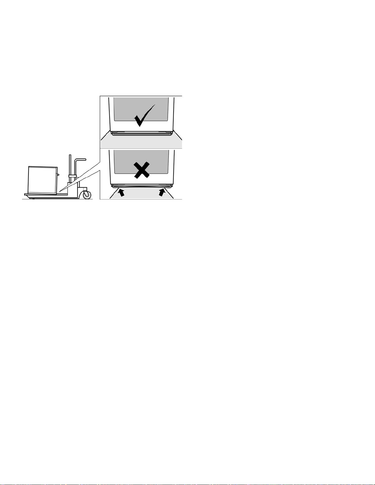
Transport
To avoid damage to the oven vent, use the transport
method shown in the picture below.
Support the bottom of the oven from side to side when
moving it into the installation location. Leave the unit
attached to the shipping pallet until it is in front of the
cabinet opening, ready to lift into place.
English 2 9000989321 Rev A

Prep aration
Before You Begin
Tools and Parts Needed
• Phillips head screwdriver
• Star-head screwdriver (T20)
• Measuring tape
• Drill with bit (1/8")
• Gloves
Parts Included
• Phillips head screws (6)
Checklist
Use this checklist to verify that you have completed each
step of the installation process. This can help you avoid
common mistakes.
___ 1. Before installing the oven, be sure to verify the
cabinet dimensions are correct for your unit and
the required electrical connections are present.
___ 2. Refer to the installation manual for content
regarding Safety, Cabinet Dimensions, Removing
Packaging, Electrical Installation, Testing the
Installation and Customer Service.
___ 3. Remove bottom hinged oven door(s) (not side
swing doors) to reduce the unit weight and to
provide access to handholds for lifting.
General Information
Power Requirements
The outlet must be properly grounded in accordance with
all applicable codes.
For Best Installation
The oven can be difficult for two people to handle during
installation. It is recommended to have three or more
people available to assist with lifting the unit into place.
Removal of the bottom hinge oven door during installation
(to provide the necessary handholds and to significantly
reduce the unit weight) can be cumbersome unless the
detailed door removal instructions are followed carefully.
Note: Do not attempt to remove the side hinge d oor ( s ome
models).
Please take time to read and follow the instructions
provided for an improved installation experience.
___ 4. Move the oven unit into place in front of the cabinet
opening, leaving the bottom packaging on the unit
to avoid damaging flooring.
___ 5 If installing a combination unit (oven and
microwave or oven and steam oven) complete the
assembly before installing the unit.
___ 6. Remove the torx head (T-20 size) screws holding
the unit to the base of the carton (using Star-head
screwdriver).
___ 7. Team lift the unit directly into the cabinet cutout
taking care not to pinch fingers or scratch hands or
arms. Make sure the electrical conduit reaches to
the connection point properly.
___ 8. Slide the unit all the way into place, making sure to
route the electrical conduit correctly.
___ 9. Fasten the oven unit to the cabinetry opening with
the screws supplied (using Philips screwdriver).
___ 10. Reinstall the oven door(s) removed in step 3
above.
___ 11. Consult the complete installation instructions and
follow the remainder of the procedures listed,
including performing an operation tes t.
___ 12. All product literature and accessories (may be
wrapped or boxed) with the oven.
___ 13. INSTALLER - Leave the literature pack and the
accessories with the customer.
9000989321 Rev A English 3
Combination Oven Pre-Assembly
Dimensions and Cabinet Requirements
Cabinet requirements vary depending on the model to be
installed. Please consult the “Cabinet Dimension
Requirements” section at the back of this installation
manual for the details pertaining to your particula r model.
All models require:
• 1/4” (6.4 mm) space between the side of the oven and
an adjacent wall or cabinet door when installed at the
end of a cabinet run.
• Installation of 2x4’s extending front to back flush with
the bottom and side of the opening to provide oven
Removing Packaging
• Cut straps on the outside of the box.
• Remove the cardboard box by lifting it up and off the
unit.
• Remove all top and side cardboard and Styrofoam
braces.
• Place the oven (leaving it on the shipping base) in front
of the cabinet where it is to be installed.
• Remove all accessories, racks, packing materials and
literature from the oven cavity (for double ovens,
remove such items, if present, from both cavities).
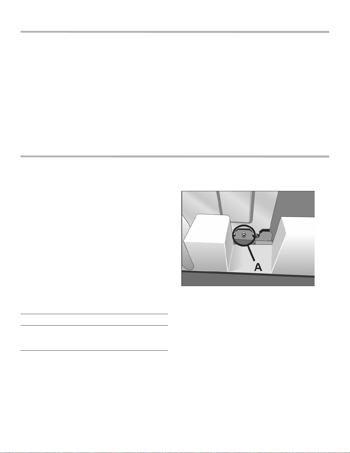
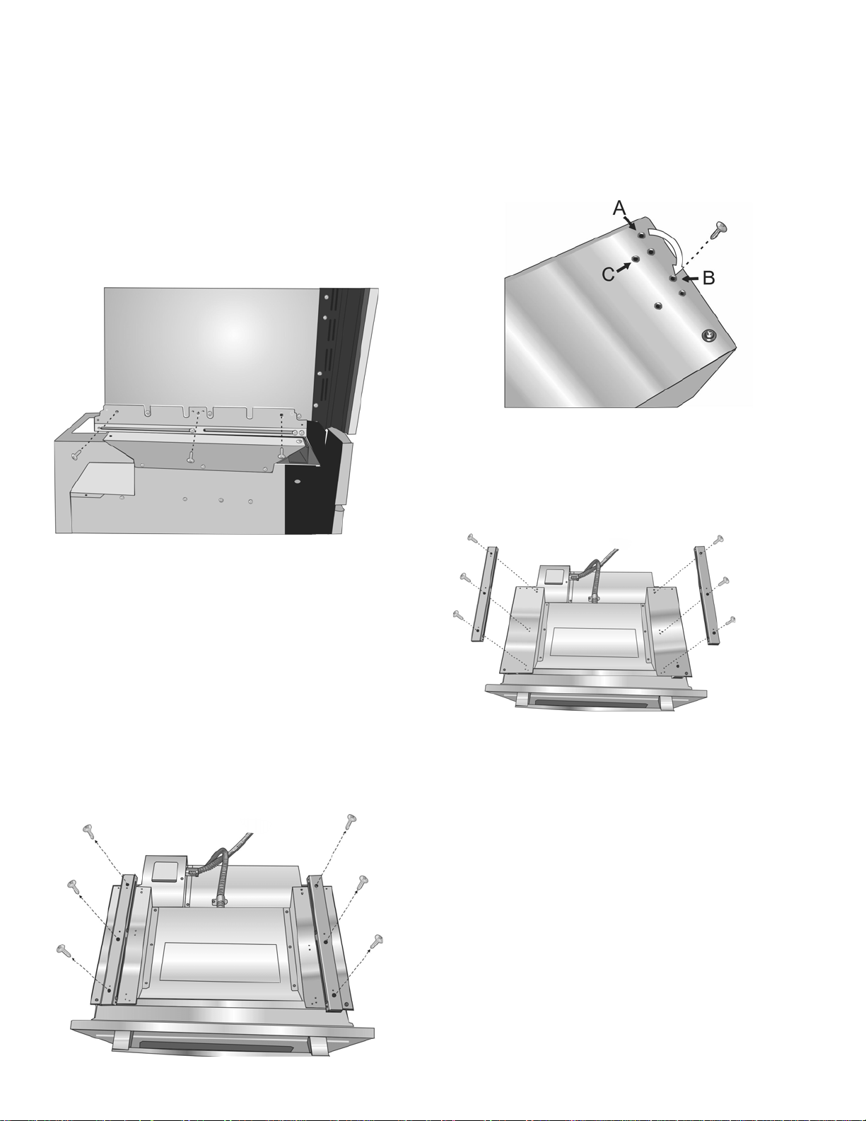
• Unscrew unit from packaging brackets as shown below
in “Packaging Bracket Removal.”
Note: The screws near the base mounting brac ket are
all torx head (T-20 size). Only the one screw that goes
through the slotted hole in the mounting bracket on the
left and right sides of the unit needs to be removed in
order to lift the unit from the mounting base (the screw
circled and shown as “A” in the following illustration.)
NOTICE
Remove one screw only from each bracket. This
will release your oven from the shipping base. Do
not remove any additional screws from the oven.
support. This supporting base must be well secured to
the floor/cabinet and must be level.
• The electrical conduit box must be located above the
unit to facilitate connecting and servicing the unit.
• The cabinet base must be flat and capable of
supporting the weight of your oven when in use (var ies
by model up to 429 lbs. (195 kg)). See the appropriate
weight for your model in the “Cabinet Dimensions
Requirements” section at the back of this installation
manual.
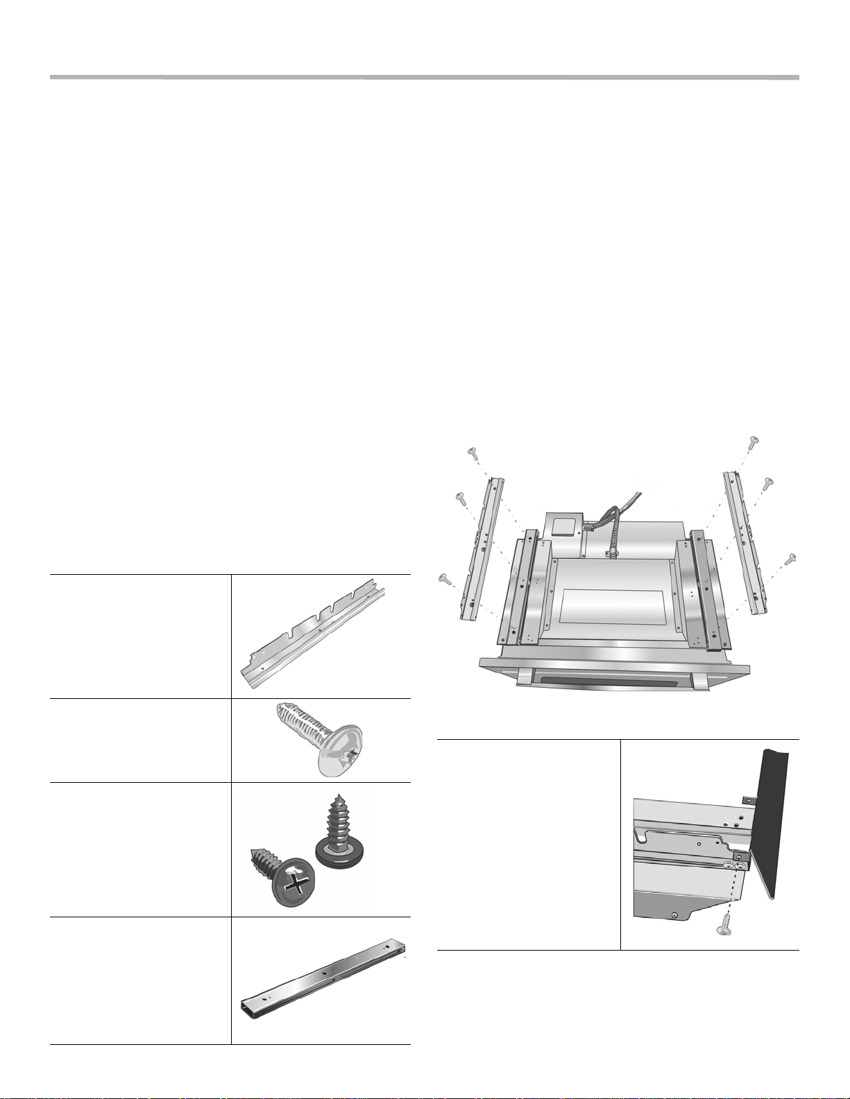
Packaging Bracket Removal (left and right
sides)
Note:
Different models use different packaging materials. Actual
brackets may look differently. The bracket remains in the
packaging base. The unit should stay on the packaging
base until ready to be lifted into cabinet cutout.
Preparing Oven
Place oven in front of the cabinet where it is to be installed
so that it is in line with the cabinet cutout.
Check to be sure all packing materials have been rem oved
from the unit. Also remove the accessories, oven racks,
literature pack and any shipping materials from inside the
oven cavity (remove from both cavities for a double oven or
combination oven).
English 4 9000989321 Rev A
Installation
Determine the Installation Type
This installation manual provides instructions for the
installation of single ovens, double ovens, and combination
ovens (a single oven combined with microwave or steam
oven).
Stand-alone single and double oven units requ ire no
pre-assembly. Unless you are installing a combination
oven, skip over the combination oven pre-assembly
instructions and go directly to “Electrical Installation”
which applies to all ovens.
Pre-Assembly of Combination Ovens
Prior to Installation
Combination ovens (with microwave or steam oven)
require the units to be assembled together prior to installing
the combination unit into the wall cabinet.
Note: The single oven can be installed with a Steam Oven
or with a Microwave Oven. The installation procedure
differs between these. The parts contained in the square
tube parts box are common to both installations.Parts
Provided
Combination Oven Installation
Installation with the Microwave Oven
Note: Do not place the oven into the wall cabinet until af ter
mounting the microwave on it using the universal connector
brackets.
1. The combo service slide assemblies are attached to
the oven spaced to accept the microwave.
2. Install both universal connector brackets using six of
the screws provided. Tighten screws securely, but do
not overtighten.
Note: The universal connector brackets are interchangeable for the left and right sides of the oven. Be sure the
taller vertical edge of the bracket is positioned to the outside of the oven.
Universal connector
bracket (2)
(in parts box on top of
oven)
Screws (16)
(in red bag, inside parts
box on top of oven)
Oven Mounting Screws
8 screws are included to
secure the oven trim to the
cabinet. The screws are
located in a small plastic
bag affixed to the literature
pack bag.
Combo service slide
assembly (2)*
* This part is
preassembled on the
oven to accomodate
attachment of a
microwave.
3. Install the decorative trim.
Position the decorative trim
piece so the flanges with
the holes in them face
away from the oven door.
Align the outer flanges with
the outside of the universal
brackets. Fasten with 1
screw each into the end
hole of the universal
bracket. Tighten screws
securely, but do not
overtighten.
9000989321 Rev A English 5
Combination Oven Pre-Assembly
4. Place the microwave oven unit on top of th e un ive rs al
connector brackets and fasten in place using three
screws per side. Tighten the screws securely, but do
not overtighten.
Note: The existing screws in the microwave base help
with alignment. When lowering the microwave into
place on the universal connector bracket, allow these
screw heads to slide into the slots as shown in the
illustration below. The screw nearest the front of the
microwave slides into the base of the slope at the front
of the bracket.
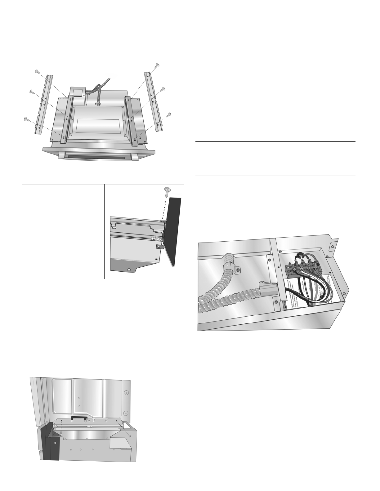
2. The screw in position A (nearest the inside edge, near
control panel) must be moved to allow the universal
bracket to be postioned there. Remove the inside
screw (A) from the left support bracket and reinsert it
into the third hole (B) from the inside edge of the
support bracket. Repeat for the right suppo rt br ac ke t.
3. Reattach the slide assemblies using the holes near the
inside edge of the support bracket. Align the slide
assembly parallel to the edge of the bracket and insert
the first screw in hole (C). Insert all three screws for
each slide assembly. Tighten the screws securely, but
do not overtighten.
5. Continue with the unit installation in the following
sections on electrical connection and installing the
oven unit into the wall cabinet.
Installation with the Steam Oven
Note: Do not place the oven into the wall cabinet until after
mounting the steam oven on it using the universal connector brackets.
1. Remove the six screws holding the combo service slide
assemblies to the support bracket. Use a magnetic
screwdriver bit to reach the screws through the large
holes in the tops of the slides.
Note: When the correct holes are used, the front of the
slide assembly will extend just past the edge of the horizontal support bar. The slide assembly will be about 1/8” (3
mm) from the inside edge of the support bracket.
4. Install the two universal connector brackets to the slide
assemblies using the screws provided. Tighte n screws
securely, but do not overtighten.
English 6 9000989321 Rev A
Note: The universal connector brackets are interchangeable for the left and right sides of the oven. Be sure the
taller vertical edge of the bracket is positioned to the outside of the oven.
5. Install the decorative trim.
Position the decorative trim
piece so the flanges with
the holes in them face
away from the oven door.
Align the inner flanges with
the inside of the universal
brackets. Fasten with one
screw each into the end
hole of the universal
bracket. Tighten screws
securely, but do not
overtighten.
7. Continue with the unit installation in the following
sections on electrical connection and installing the
oven unit into the wall cabinet.
Connecting the Microwave Oven or Steam Oven
Electrical Conduit to the Single Oven
Note: If installing the oven with a microwave or steam oven
mounted as a combination unit, the microwave oven or
steam oven power cable must be proper ly attache d to th e
oven-mounted junction box. This must be done prior to
supplying electric power to the oven unit.
9 WARNING
Disconnect the oven from the electric power supply
before connecting the microwave ov en or ste am
oven wiring. Failure to do so could result in electrical
shock and injury or death.
1. Check to be sure there is no electric power supplied to
the oven.
2. Remove the oven mounted junction box cover (located
on the rear top of the oven).
3. Remove the cap from the conduit access hole in the
side of the oven mounted junction box.
6. Place the steam oven unit on top of the universal
connector brackets and fasten in place using two
screws per side. Tighten the screws securely, but do
not overtighten.
Note: The existing screws in the steam oven base help
with alignment. When lowering the steam oven into
place on the universal connector bracket, allow these
screw heads to slide into the slots as shown in the
illustration below. The screw nearest the front of the
steam oven slides into the base of the slope at the front
of the bracket.
4. Guide the four wires from the conduit cable coming
from the microwave or steam oven through the hole in
the oven mounted junction box.
5. Snap the conduit connector into the hole by pressing it
in until it clicks into place.
6. Follow the wiring diagram label and match and conn ect
each wire by color to the wires attached to the wiring
block inside the oven mounted junction box. Push the
bare end of the wire until it is snug in the wiring block
then tighten down the retaining screw on each wire.
Tighten securely, but do not over tighten.
7. Replace the oven mounted junction box cover and
tighten the two screws holding it in place. Tighten the
screws securely, but do not over tighten.
9000989321 Rev A English 7
8. Refer to the Electrical Connection section for further
information to complete the electrical connection of the
combination unit to the main power supply.
Electrical Installation
All model ovens on the front cover of this installation
instruction manual are dual rated, designed to be
connected to either 208 or 240V AC, 60 Hz, 4 wire, singlephase power supply.
Model Circuit Required
208V, 60 Hz 240V, 60 Hz
HBN54, HBN84,
HBL53, HBL54,
HBL84, HBLP4
HBL55
HBN56, HBL56,
HBL57, HBN86,
HBL86, HBL87,
HBLP6, HBLP7,
HSLP7
30 AMP 40 AMP
30 AMP
40 AMP
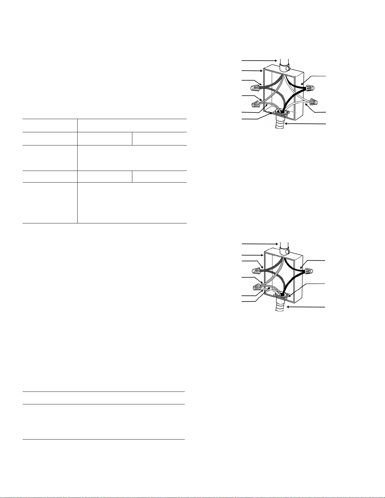
Four-wire Connection
Ungrounded Neutral
power supply
junction box
red wires
green or bare
wire
green wire
UL listed
connector
black wires
white wires
cable from
oven
• Connect the red oven wire to the red electrical sup ply
wire (hot wire).
• Connect the black oven wire to the black electrical
supply wire (hot wire).
• Connect the white neutral oven wire to the white
neutral (not bare or green ground) electrical supply
wire.
• Connect the green ground oven wire to the bare or
green ground electrical supply wire.
Three-wire Connection
The electrical supply should be a 4-wire single-phase AC.
Install a suitable conduit box (not furnished). An
appropriately-sized, UL-listed conduit connector must be
used to correctly attach the conduit to the junction box.
Important: Local Codes may vary; installation, electrical
connections and grounding must comply with all applicable
local codes.
If local codes permit grounding through the electrical
supply neutral, connect both the white neutral wire and the
green ground wire from the oven to the white neutral
electrical supply wire.
Important: If you have purchased a combination oven unit
(one that includes a microwave or steam oven over the
single oven), see the preceding section “Connecting the
Microwave Oven or Steam Oven Electrical Conduit to the
Single Oven” showing electrical connection of the
combination unit components.
9 WARNING
Complete the connection of the microwave or steam
oven conduit to the single oven before proceeding
with the unit electrical connection to the main power
supply.
Grounded Neutral
power supply
junction box
red wires
white, bare, or
green wire
white wire
green wire
black wires
UL listed
connector
cable from
oven
• Connect red wire from oven to red wire in junction box.
• Connect black wire from oven to black wire in junction
box.
• Connect both green ground wire and white wire from
oven to white, green or bare neutral wire in junction
box.
The conduit cable, where connected at the oven, swivels.
Rotate conduit cable upward (or downward) and direct
through hole prepared in cabinet to attach to J-Box.
To maintain serviceability, the flex conduit must not be
shortened and should be routed to permit temporary
removal of the oven.
Electrical Connection to Main Power Supply
The four-wire connection is preferred, but where local
codes permit, the three wire connection is also acceptable.
English 8 9000989321 Rev A
Installing the Oven Unit into
the Wall Cabinet
NOTICES
Before installing the oven, be sure to verify the
cabinet dimensions and electrical
connections.Check that the cabinet opening is level
and plumb for correct installation.
Combination units (ovens with a microwave or
steam oven) have additional installation in structions.
Please see the preceeding section “Pre-Assembly
of Combination Ovens Prior to Installation”.
For Best Installation
The double and combination ovens can be difficult for two
people to handle during installation. It is recommended to
have three or more people available to assist with lifting the
unit into place. It is also recommended to remo ve the oven
door (bottom hinge models only) to help reduce the unit
weight and provide easier access to the handholds located
inside the oven.
Caution
: It is recommended to wear gloves and long sleeves to
protect hands and forearms from abrasion and potential
scratches during the lifting process. It is also recommended
to take off watches and jewelry and to wear work shoes
during installation for foot protection.
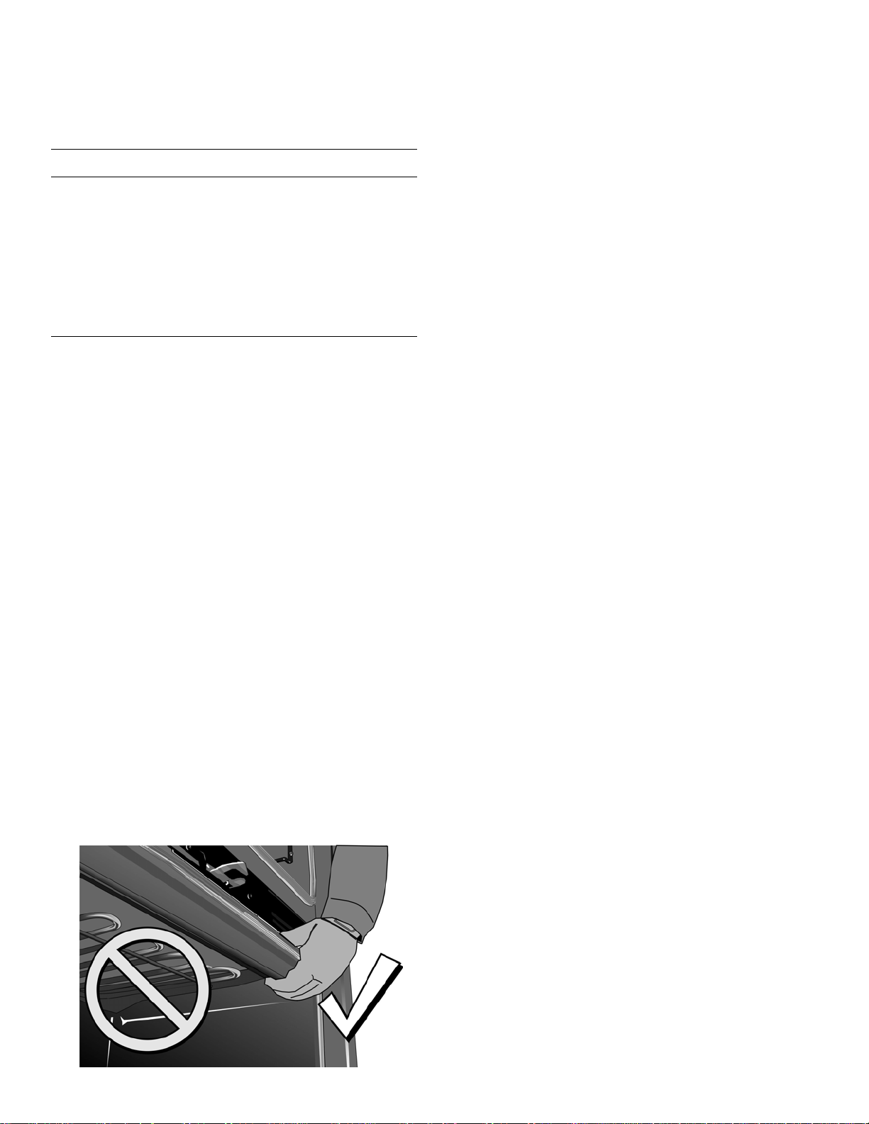
Correct Inside Oven Lift Point
Notice: DO NOT attempt to lift the unit by holding the oven
upper element.
There is a ridge across the top front of the oven cavity. Lift
by grasping this ridge with one hand while placing the other
hand on the back of the unit (for helpers lifting from the
sides of the unit). If a third helper is lifting from the front,
both hands should lift by holding this ridge area.
9000989321 Rev A English 9
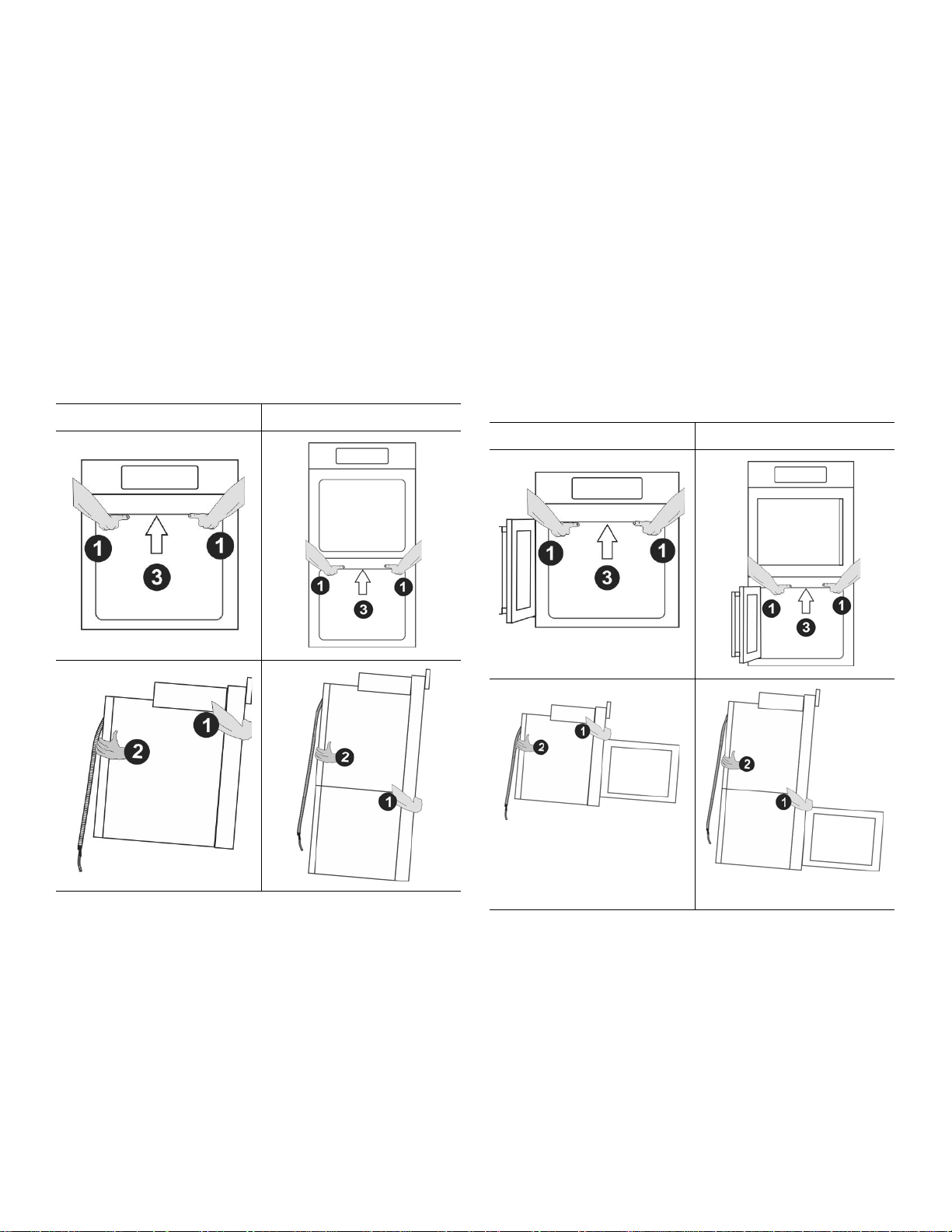
Lifting Recommendations Vary Dependent Upon Oven Door Type
Bottom Hinge Door
Side Hinge Door
Lift Locations (with door(s) removed)
Lift Locations (with lower door opened to 90°-110°)
Lift points (1) on the front of the unit are for lifting from the
sides of the unit. Lift point (3) on the front of the unit is for a
third person to help lift the unit.
Lift point (2) on the back of the unit shows the location of
the opposite hand for the helpers lifting from the sides of
the unit. Adjust the location as needed to facilitate the lift.
Wear gloves, a long sleeved shirt, and avoid sharp edges
to reduce the risk of cuts or abrasions to the arms or hands.
Single Oven Double/Combo Oven
Lift points (1) on the front of the unit are for lif ting from the
sides of the unit. Lift point (3) on th e fr ont of th e unit is fo r a
third person to help lift the unit.
Lift point (2) on the back of the unit shows the location of
the opposite hand for the helpers lifting from the sides of
the unit. Adjust the location as needed to facilitate the lift.
Wear gloves, a long sleeved shirt, and avoid sharp edges
to reduce the risk of cuts or abrasions to the arms or hands.
Single Oven - Side Swing Double Oven Side Swing
English 10 9000989321 Rev A
Installing the Oven
9 WARNING
• Make sure oven is cool and power to the oven
has been turned off before removing the door.
Failure to do so could result in burns.
• The oven door is heavy and fragile. Use both
hands to remove the oven door . The door front
is glass. Handle carefully to avoid breaking.
• Grasp only the sides of the oven door. Do not
grasp the handle as it may swing in your hand
and cause damage or injury.
• Failure to grasp the oven door firmly and
properly could result in personal injury or
product damage.
• To avoid injury from hinge bracket snapping
closed, be sure that both levers are securely in
place before removing the door. Also, do not
force door open or closed - the hinge could be
damaged and injury could result.
• Do not lay removed door on sharp or pointed
objects as this could break the glass. Lay on a
flat, smooth surface, positioned so that the
door cannot fall over.
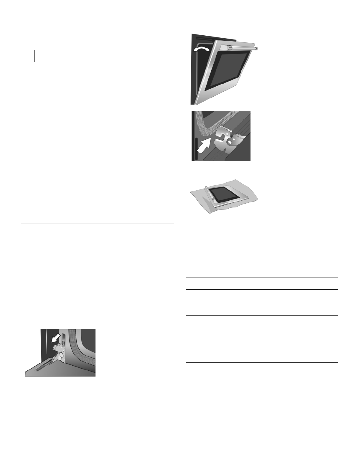
Bottom Hinge Doors Only - Remove
Prior to Install
4. Holding the door firmly
on both sides and
using both hands,
close the door gently
until it stops against
the latch levers, about
30º from the closed
position.
5. Carefully lift the door
up and out of the
hinge slots. Hold
firmly; the door is
heavy.
6. Place the door in a
convenient and stable
location until you are
ready to reinstall it.
Lay the door on a
towel or section of
protective foam
padding to avoid
damage to the door or
the floor.
Important: Do not attempt to remove the side hinge
door (side hinge doors are found only on select models).
Ovens with bottom hinge doors permit the oven door(s) to
be removed prior to lifting the unit into place. Each door
weighs approximately 40 pounds (18.1 kg). Removing and
replacing the door are routinely simple procedures.
Removing the door lightens the unit significantly an d
provides easier access to the recommended handhold
inside the oven cavity. See instructions below.
1. Be sure to read all
warnings and cautions
in the installation
manual regarding the
door removal before
attempting to remove
the door.
2. Open the door
completely.
3. Flip latch levers on
hinges toward you.
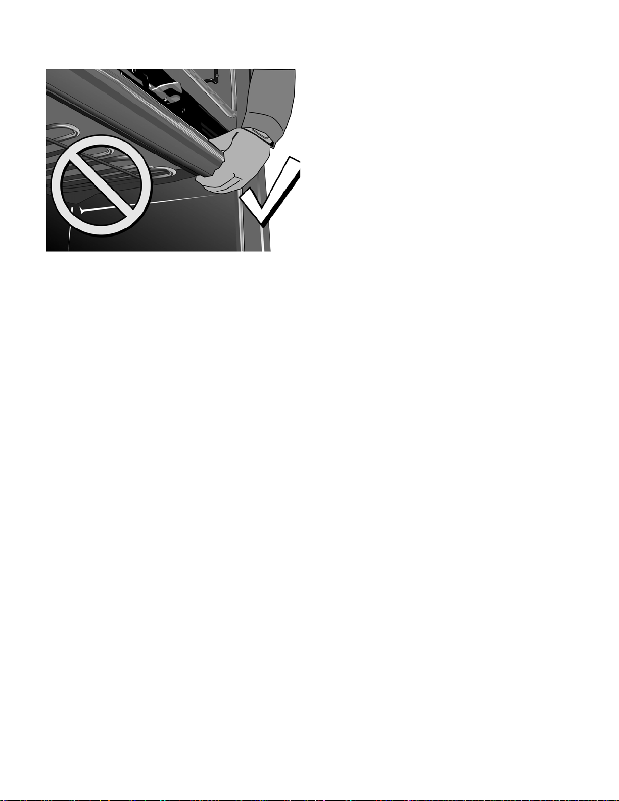
Placing the Oven Into the Cabinet
Opening - All Ovens
9 CAUTION
To avoid damage to the door do not lift, pull or push
the unit during installation by using the oven door
handle as a gripping point.
It is recommended to wear gloves and long sleeves
to protect hands and forearms from abrasion and
potential scratches during the lifting process. It is
also recommended to take off watches and jewelry
and to wear work shoes during installation for foot
protectio
When lifting the unit into place avoid grasping the upper
element to avoid damaging it. See the illustration following
for the correct lifting point for a bottom hinge double oven
with the lower door removed. This illustration shows a
detailed view of the oven cavity. Note the location of the
ridge inside the top of the cavity. This is the area to grip
from the front when lifting the oven.
For your particular oven type, see the preceeding section
“Lifting Recommendations Vary Dependent Upon Ov en
Door Type” for lift points.
9000989321 Rev A English 11
Installing the Oven into the Cabinet (all
ovens)
1. The unit and its bottom packaging (wood and
styrofoam base) should be positioned close to and in
front of the cabinet opening prior to beginning to lift the
unit into place.
2. Lift or slide unit into the cabinet cutout without allowing
the unit base to contact the flooring.
3. Check that the conduit cable does not fall behind the
unit during installation. It may help to run the conduit
into the area it will be connected to (such as an
overhead or adjacent cabinet) and tape the end down
so it doesn’t fall out while the unit is being slid into
place.
4. Guide the unit straight back into the cabinet cutout.
Note: Be careful not to crimp the flexible conduit
between the oven and the cabinet back wall. If
necessary, guide the flexible conduit into the wall or
cabinet access hole so it doesn’t prevent the unit from
being pushed all the way into the cabinet opening. The
oven should be straight and level, not crooked.
5. Push the unit straight in until the oven trim is flush with
the front of the cabinet trim.
6. Install supplied screws through tap holes in trim.
(2 screws for single ovens, 4 screws for double/combo
ovens).
English 12 9000989321 Rev A

Ovens with Bottom Hinge Doors Only
Fig. B
Fig. A
Ovens with Side Hinge Doors Only
Re-Install the oven doors:
1. Hold the door firmly in
2. Hold the door at a 30º
3. The door may need to
4. Open door all the way
5. Push latch levers
6. Close and open door
both hands.
angle from the closed
position and insert
hinges into the slots.
You may need to rock
the door forward and
backward slightly to
seat the hinge feet.
be removed and reinserted until the
hinges sit correctly in
the slots.
to expose hinges,
latch levers, and slots.
forward and down until
seated on the bracket.
slowly to be sure it is
correctly and securely
in place. Door must be
straight, not crooked.
Side Hinge Door Aligment
Note: Only align the side hinge oven doors after the unit is
fully installed into the cabinet.
1. Check to see if the
side hinge oven doors
are properly aligned.
The door should pull
itself closed smoothly
when the striker
engages the roller as
the door is closed.
2. Too high (Fig. A - door
needs to move down
on latch side) you will
feel interference
between the striker
and the catch receiver.
3. Too low (Fig. B - door
needs to move up on
latch side) you will feel
a bump when the
striker comes into
contact with the realignment roller.
Hint: The gap between
the top of the closed
oven door and the
control panel (or upper
door for lower cavities
in double ovens)
should be fairly
uniform from side to
side.
9000989321 Rev A English 13
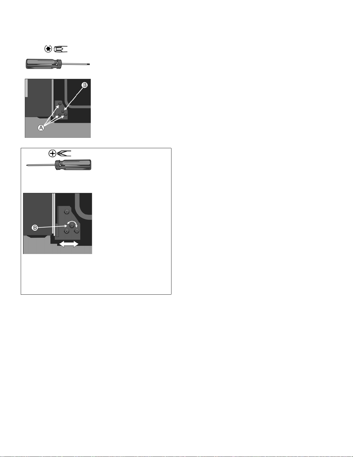
Side Hinge Door Alignment Procedure
1. Open the door to
approximately 135°.
2. Using a Torx T-20 starhead screwdriver,
loosen the 3 screws
(A) on the lower hinge
by 1 to 2 full turns.
Note: All adjustment is
made with the lower
hinge only. The upper
hinge is fixed in place
and cannot be
adjusted.
3. Using a #2 philips
head screwdriver, turn
the cam (B) right or left
to adjust the hinge
position in the desired
direction.
Note: 1mm of hinge
movement (left or
right) will move the
door up or down
approximately 1.5mm
at the door catch.
4. Re-tighten the screws
before closing the
door to test. Be careful
not to overtighten.
5. Check for proper door
alignment. Repeat
adjustment procedure
as necessary.
English 14 9000989321 Rev A

Side Hinge Door Opening/Closing Troubleshooting Guide
Primary observation Additional observations Cause: Solution
The door does not pull
itself closed and feels
difficult to open as well.
The door does not hold
itself closed.
The door does not close
onto the striker
smoothly.
Once closed, the door
opens without incident.
The door does not close
onto the striker
smoothly.
Once closed, the door
may also appear to
stick while pulling the
door open
The side edge of the inner
door (on the handle side of
the door) appears to make
contact with the unit's side
trim.
Very little force is required
to pull open the door.
When closing the door onto
the striker, the door lifts
itself upwards.
You will feel a slight bump
as the roller (internal to the
door) hits the tip of the
striker and lifts the door.
If the door needs to lift
substantially, the door will
no longer pull itself closed,
and assistance is required
to push it closed fully.
While trying to open the
door from a closed position,
you feel an interference that
catches the door and may
prevent it from opening.
You feel a similar
interference when closing.
The installation is
causing the side
trim to be pushed
too far inwards.
The door catch
mechanism
internal to the
door has
inadvertently
tripped while the
door was open.
The door
alignment is too
low to engage
properly with the
striker.
See figure B in the
side hinge door
alignment
instructions.
The door
alignment is too
high to engage
properly with the
striker.
See figure A in the
side hinge door
alignment
instructions.
Check the installation of the unit in the
cabinetry. Try to move the unit in the cabinet
towards the side of the hinges as much as
possible to allow the interfering side trim to
open up.
May also try to adjust the location of the side
trim screws to hold the trim away from the
door.
Check again the cabinet opening to ensure
that it is not too narrow. Widen the cutout as
necessary.
To reset the mechanism, close the door
completely and while closed, push in firmly on
the door handle until the mechanism resets.
A firm push may be required. Open to test.
Refer to the side hinge door alignment
procedure to raise the handle side of the door
until the door closes smoothly.
It should open smoothly and pull itself closed
smoothly without hearing or feeling an
interference.
To open a sticking door, apply pressure
downward on the handle while pulling.
Refer to the side hinge door alignment
procedure to lower the handle side of the door
until the door closes smoothly.
It should open smoothly and pull itself closed
smoothly without hearing or feeling an
interference.
9000989321 Rev A English 15
Testing Operation
Data Plate
1. Turn on power at the breaker.
2. Test the oven mode.
Select the BAKE mode. See the Use and Care Manual
for detailed operation instructions.
3. Verify that the oven light comes on and the oven be gins
to preheat.
4. Test the door lock.
Set the SELF CLEAN mode. Confirm that the door
locks when the lock icon appears in the display.
5. If installing a double oven, test the second oven as
well.
6. If any of the tests do not result as explained above,
contact Bosch service for assistance. Otherwise, the
installation is complete at this time.
Before Calling Service
Seethe Use and Care Manual for troubleshooting
information. Refer to the Statement of Limited Warranty in
the Use and Care Manual.
To reach a service representative, se e the contact
information at the front of the Use and Care Manual.
Please be prepared with the information printed on your
product data plate when calling.
The data plate shows the model and serial number. Refer
to the data plate on the appliance when requesting service.
The data plate location varies based on the oven model
and door hinge type.
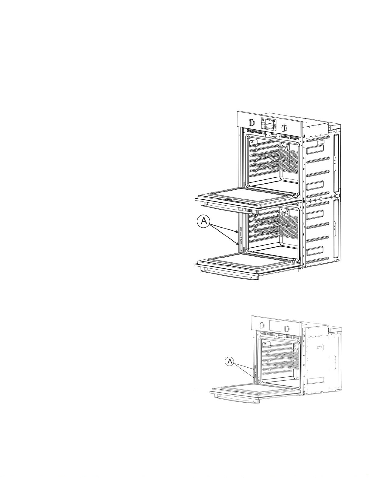
Double Ovens, Bottom Hinge
Note: The rating plates (A) are at the left hand side of
the door trim of the lower oven cavity.
Single Ovens, Bottom Hinge
Note: The rating plates (A) are at the left hand side of
the door trim.
English 16 9000989321 Rev A
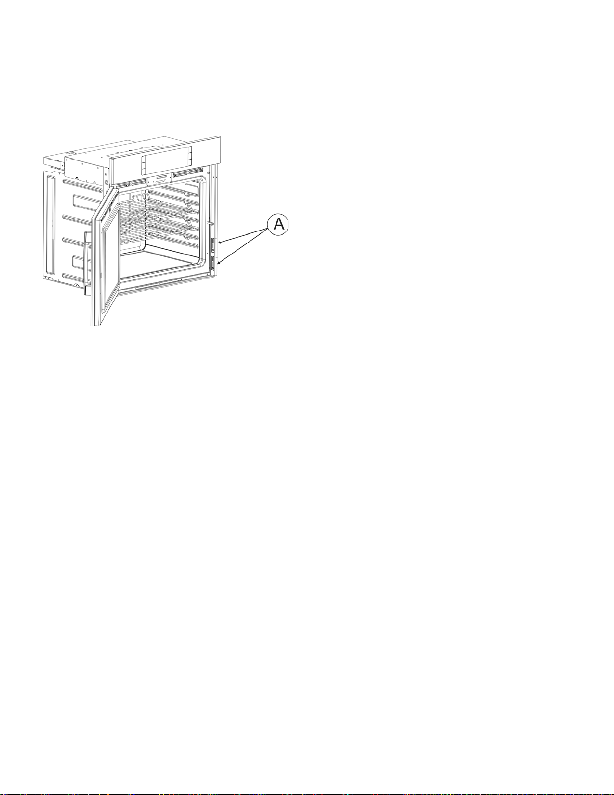
Single Ovens, Side Hinge
Note: The rating plates (A) are opposite the door hinge.
For left hinge doors, the rating plates will be on the door
trim on the right hand side of the door. For right hinge
doors, the rating plates will be on the door trim on the
left hand side of the door.
Double Ovens, Side Hinge
Note: The rating plates are opposite the door hinge in
the lower oven cavity.
9000989321 Rev A English 17
Cabinet Dimension Requirements
It is good practice, when an oven is installed a t the end of a
cabinet run, adjacent to a perpendicular wall, or cabinet
door, to allow at least 1/4” (6 mm) space between the side
of the oven and the wall/door.
For oven support, install 2x4’s extending front to back flush
with the bottom and the side of the opening. The supporting
base must be well secured to the floor/cabinet and level.
Junction boxes can be located anywhere within reach of
the oven’s power cable.
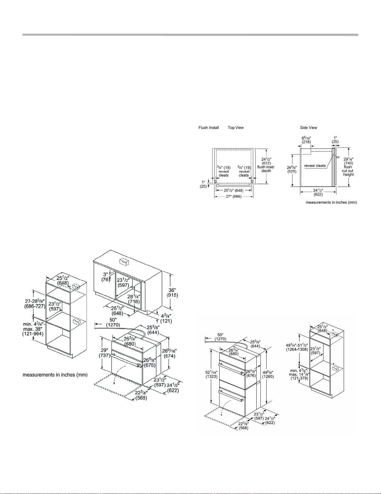
Dimensions for 27” Single
Oven Units
The cabinet opening must be plumb and the base must be
flat and level and capable of supporting a weigh t of at least
193 lbs (87 kg).
Single Oven 27” Traditional Installation,
Cabinet and Undercounter
Single Oven 27” Flush Mount
Installation
Flush installation (wall mount and undercounter) requires
two side cleats to be attached inside the cabin et or counter
frame, recessed from the front.
Dimensions for 27” Double
Oven Units
The cabinet opening must be plumb and the base must be
flat and level and capable of supporting a we ight of at least
361 lbs (164 kg).
Double Oven 27” Traditional
Installation
English 18 9000989321 Rev A
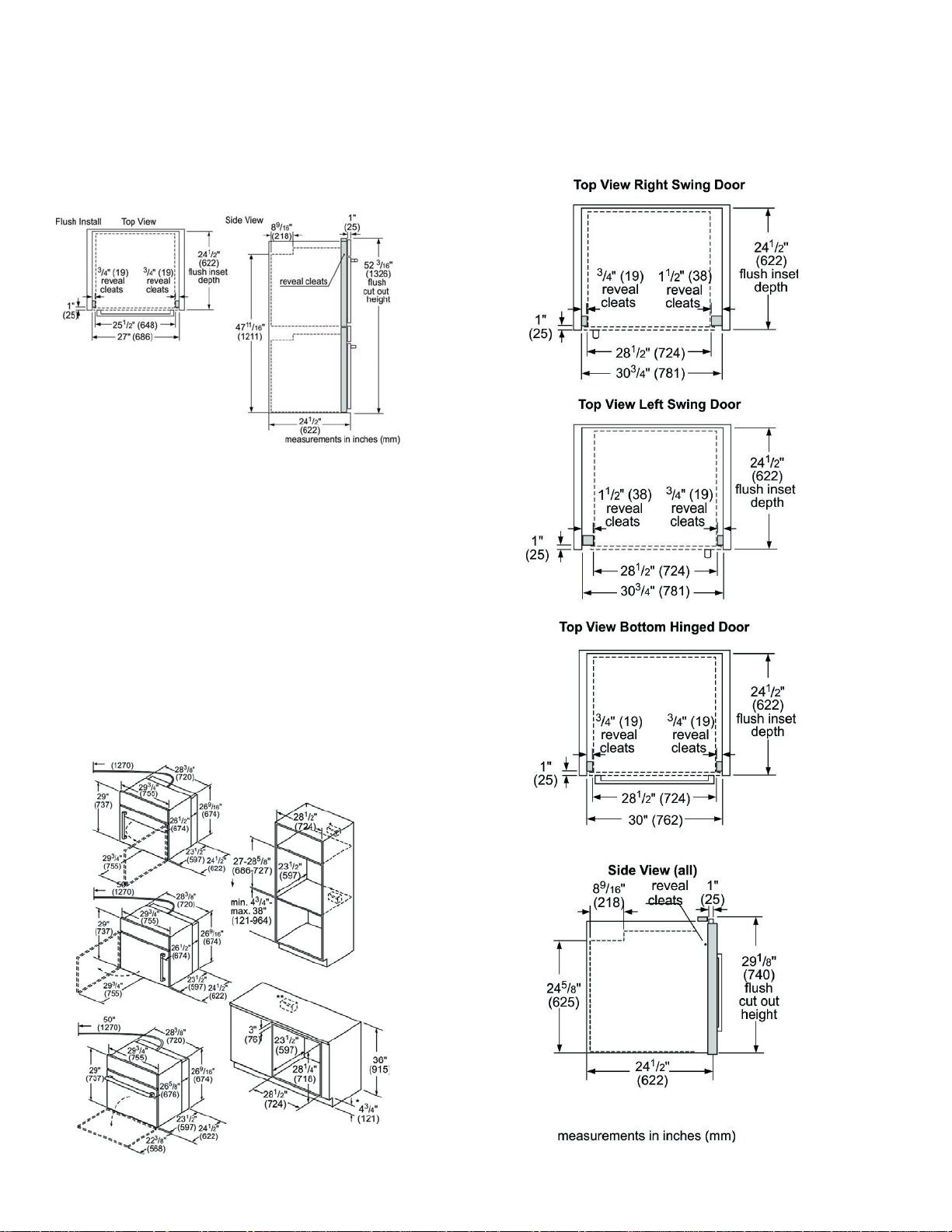
Double Oven 27” Flush Mount
Single Oven 30” Flush Mount
Installation
Flush installation requires two side cleats to be attached
inside the cabinet frame, recessed from the front.
Dimensions for 30” Single
Oven Units
The cabinet opening must be plumb and the base must be
flat and level and capable of supporting a weigh t of at least
212 lbs (96 kg).
Installations
Flush installation requires two side cleats to be attach ed
inside the cabinet frame, recessed from the front.
When installing a side hinge oven, leave at least 10” (254
mm) clearance to allow the door to open.
Single Oven 30” Traditional Installation,
Cabinet and Undercounter
9000989321 Rev A English 19
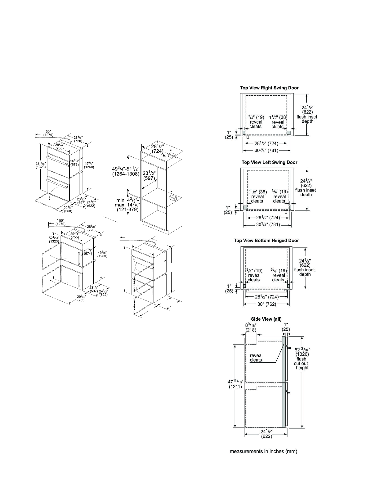
Dimensions for 30” Double
29 / "
(755)
3
4
52 / "
(1323)
1
16
49 / "
(1260)
5
8
50"
(1270)
28 / "
(720)
3
8
24 / "
(622)
1
2
29 / "
(755)
3
4
23 / "
(597)
1
2
26 / "
(674)
1
2
Oven Units
Double Oven 30” Flush Mount
Installion
The cabinet opening must be plumb and the base must be
flat and level and capable of supporting a weigh t of at least
390 lbs (177 kg).
Double Oven 30” Traditional
Installation
Double Oven 30” Flush installation requires two side cleats
to be attached inside the cabinet frame, recessed from the
front.
English 20 9000989321 Rev A
 Loading...