

Bosch Benchmark HGIP056UC, HDIP056U Installation Manual
LP Gas Conversion Kit
Installation Manual
Slide-in Ranges
HDIP05
HGI8046UC, HGI8056UC, HGIP056UC
6U, HDIP056C, HDI8056U, HDI8056C,


Table of Contents
Safety Definitions . . . . . . . . . . . . . . . . . . . . . . . . . . . . 1
IMPORTANT SAFETY INSTRUCTIONS . . . . . . . . . . .2
Conversion . . . . . . . . . . . . . . . . . . . . . . . . . . . . . . . . . . 3
Before You Begin . . . . . . . . . . . . . . . . . . . . . . . . . . . . .3
Procedure . . . . . . . . . . . . . . . . . . . . . . . . . . . . . . . . . . . 3
Test the Installation . . . . . . . . . . . . . . . . . . . . . . . . . . . .7
Service . . . . . . . . . . . . . . . . . . . . . . . . . . . . . . . . . . . . . 9
Before Calling Service . . . . . . . . . . . . . . . . . . . . . . . . . . 9
This Bosch Appliance is made by
BSH Home Appliances Corporation
1901 Main Street, Suite 600
Irvine, CA 92614
Questions?
1-800-944-2904
www.bosch-home.com/us
We look forward to hearing from you!
Safety Definitions
9 WARNING
This indicates that death or serious injuries may
occur as a result of non-observance of this warning.
9 CAUTION
This indicates that minor or moderate injuries may
occur as a result of non-observance of this warning.
NOTICE: This indicates that damage to the appliance or
property may occur as a result of non-compliance with this
advisory.
Note: This alerts you to important information and/or tips.
WARNING:
If the information in this manual is not followed exactly, a
fire or explosion may result causing property damage,
personal injury or death.
-- Do not store or use combustible materials,
gasoline or other flammable vapors and liquids
in the vicinity of this or any other appliance.
-- WHAT TO DO IF YOU SMELL GAS
• Do not try to light any appliance.
• Do not touch any electrical switch.
• Do not use any phone in your building.
• Immediately call your gas supplier from a
neighbor’s phone. Follow the gas supplier’s
instructions.
• If you cannot reach your gas supplier, call
the fire department.
-- Installation and service must be performed by a
qualified installer, authorized service agency or
the gas supplier.
English 1

9 IMPORTANT SAFETY INSTRUCTIONS
READ AND SAVE THESE INSTRUCTIONS
Safety
9 WARNING
If the information in this manual is not followed
exactly, fire or shock may result causing property
damage or personal injury.
Important Safety Instructions
• Please read Installation Instructions before beginning
the conversion.
• Please read all instructions before proceeding. Save
the natural gas parts for possible conversion from LP
back to natural gas in the future.
• This kit is used to convert dual fuel ranges and gas
ranges from natural gas operation to propane (LP) gas
operation. This conversion kit is only for use with BSH
Home Appliances manufactured ranges.
• CAUTION: When connecting the unit to the propane
gas, make certain the propane gas tank is equipped
with its own high pressure regulator. In addition, the
range has its own pressure regulator. Verfiy that it is
installed for the appropriate gas supply.
• The maximum gas pressure to this appliance is not to
exceed 14.0 inches water column from the propane
gas tank regulator.
• The following must be met when testing supply piping
system:
a) The appliance and its individual shut-off valve must
be disconnected from the gas supply piping system
at test pressures in excess of 1/2 psig (3.5 kPa).
b) The appliance must be isolated from the gas sup-
ply piping system by closing its individual manual
shut-off valve during any pressure testing of the
gas supply piping system at test pressures equal to
or less than 1/2 psig (3.5 kPa).
• WARNING: This conversion kit shall be installed by a
qualified service agency in accordance with the
manufacturer's instructions and all applicable codes
and requirements of the authority having jurisdiction. If
the information in these instructions is not followed
exactly, a fire, explosion or production of carbon
monoxide may result causing property damage,
personal injury or loss of life. The qualified service
agency is responsible for the proper installation of this
kit. The installation is not proper and complete until the
operation of the converted appliance is checked as
specified in the manufacturer's instructions supplied
with the kit.
• For Massachusetts Installations:
1) Installation must be performed by a qualified or
licensed contractor, plumber or gas fitter qualified
or licensed by the state, province or region where
this appliance is being installed.
2) Shut-off valve must be a "T" handle gas cock.
3) Flexible gas connector must not be longer than 36
inches.
• High Altitude Installation Note: For high altitude
installations, please refer to customer service.
Proposition 65 Warning:
This product may contain a chemical known to the State
of California, which can cause cancer or reproductive
harm. Therefore, the packaging of your product may bear
the following label as required by California:
67$7(2)&$/,)251,$352326,7,21:$51,1*
:$51,1*
&DQFHUDQG5HSURGXFWLYH+DUPZZZ3:DUQLQJVFDJRY
English 2

Conversion
Before You Begin
Tools and Parts Needed
• 7 mm Socket Driver w/ 3" extension
• Torx (T20)-head screwdriver
• Adjustable Wrench
• Flathead Screwdriver (1/8" or smaller)
• Phillips Head Screwdriver
Parts Included
• Conversion Kit Instructions
• Conversion Sticker
• 7 LP Orifices
• 1 Broil Orifice Hood (models that are all gas only)
• LP Conversion Jig (models that are all gas only)
Note: This manual supports two different SIR models (dual
fuel and gas), thus some parts listed may not be present if
it doesn’t pertain to the model purchased.
General Information
Always Provide Adequate
Gas Supply
This appliance is shipped from the factory for use with
natural gas. Use this kit to convert the appliance for LP gas
use if necessary. Observe the following:
Be sure the range is converted for use with the appropriate
gas before using it.
This appliance is designed to operate at a pressure of 10"
of water column when used with LP gas.
When checking for proper operation of the regulator, the
inlet pressure must be at least 1" greater than the operating
(manifold) pressure above. When converting for LP gas
use, the pressure supplied to the regulator must be
between 11" and 14" of water column.
The pressure regulator located in the inlet of the range
manifold must remain in the supply line.
Use a flexible metal appliance connector or rigid pipe to
connect the Range to the gas supply. The connector
should have an inner diameter of 1/2" and be 5' in length.
(Exception: Maximum connector length in Massachusetts
installations is 3'). In Canada, the connector must be single
wall metal and not longer than 6'.
Preparation
CAUTION: Turn off Gas and Electricity
Before proceeding with the conversion; shut off the gas
supply to the appliance prior to disconnecting the electrical
power.
1. Turn all control knobs to the "OFF" position.
2. Shut off the outside propane tank gas valve to the
range.
3. Remove range power cord from electrical outlet or turn
breaker off at breaker box.
English 3
Procedure
r
Replace Cooktop Orifices
Convert Pressure Regulator from
6" W.C. to 11" W.C.
1.2.Remove warming drawer; pull drawer out until stop is
reached. Facing the range, push clip on left side up
and clip on right side down. Pull drawer the rest of the
way out.
Remove cover plate from interior back wall by
removing single screw on left side of panel. Use a torx
T-20 head screwdriver.
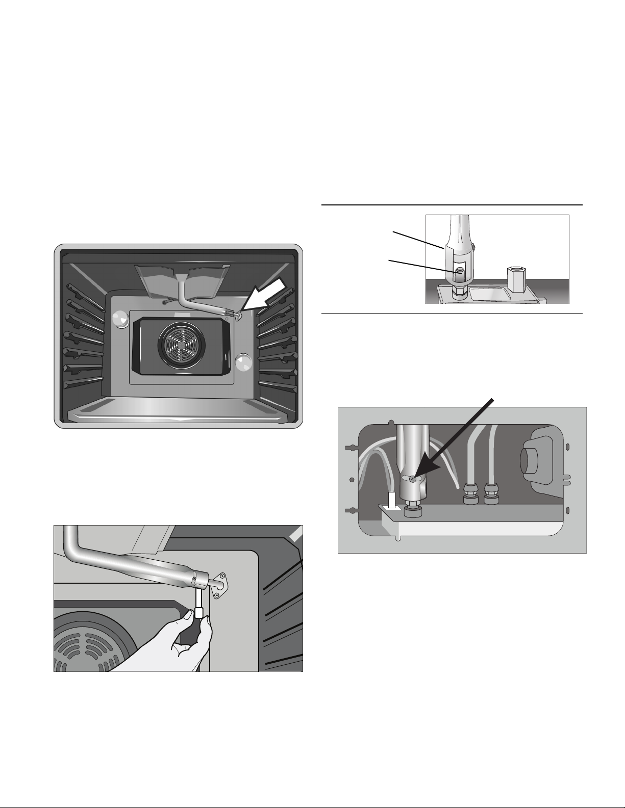
3. Remove the hexagon cap from the top of the regulator
with an adjustable wrench.
4. Pop out the plastic stem in the cap and turn it over
pressing it firmly in place so that the letters "LP" (rather
than "NAT") are seen upright in the stem.
Replace the cap and button assembly into the top
of the regulator sealing it firmly. Make certain
spring is still in place (See Fig. 1). DO NOT
OVERTIGHTEN.
Pin Position
for Propane
Hex
Cap
Pin
Pin
Position
for Nat.
Gas
Hex
Cap
Pin
NA
T
NAT
5. Fill out and affix the CONVERSION STICKER on the
back side of the cover plate so that it appears on the
back side of range next to the regulator.
LP
LP
Spring
Figure 1: Pressure Regulator
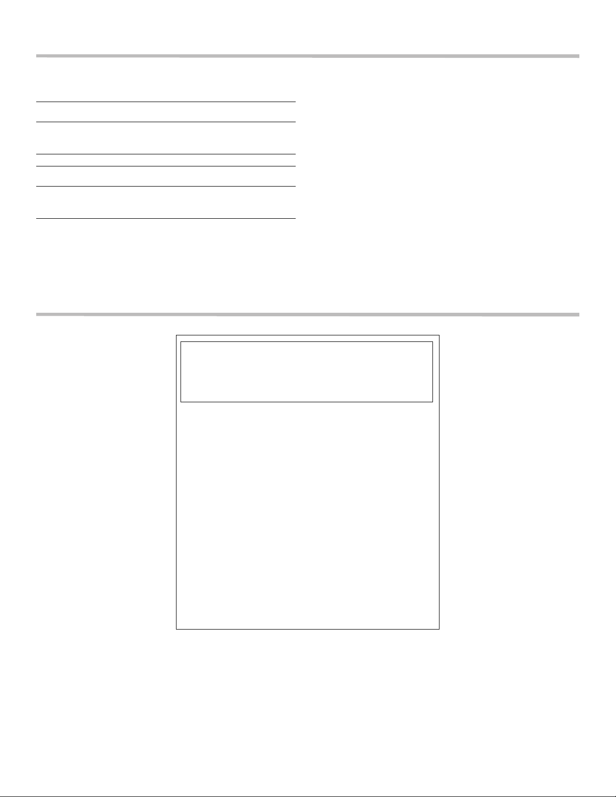
1. Remove grates, burner caps and burner bases.
Unscrew two (2) T20 screws inside each base and
remove burner bases. Reinsert screws in jet holder to
hold tubing assembly in place.
Burner Grate
Burner Cap
Burner Base
Orifice
Ignito
Figure 2: Sealed Gas Burners
2. Remove natural gas cooktop orifices.
Insert the socket driver with 3" minimum extension into
the jet holders to remove existing orifices. Set natural
gas orficies aside.
3. Assemble LP cooktop orifices.
Place in cooktop exactly as specified on the orifice
card. Placement can be determined by matching the
orifice size to the number on the card.
4. Place the new orifice into the socket then insert each
orifice into its respective threaded hole in the jet holder.
Tighten until the orifice stops turning. DO NOT
OVERTIGHTEN.
5. Remove screws placed in jet holder to replace burner
base, burner cap and burner grate. Reinstall screws.
Note: Burner cap must be properly positioned on
burner base for burner to light.
Correct Burner Cap
Placement
Incorrect Burner Cap
Placement
Burner Cap Placement
6. Retain natural gas orifices for future conversion back to
natural gas.
English 4
Convert Cooktop Valves for
Propane Use
LP Gas Conversion Dual Valve
(some models):
1. Verify that all knobs are in the OFF position.
2. Remove knobs (pull straight out).
3. Insert 1/8” (or smaller) flat head screwdriver into shaft
and turn bypass screw clockwise until it stops (bypass
screw is inside shaft). DO NOT OVERTIGHTEN.
Bypass Screw Inside Shaft
4. Replace knobs.
If your range is dual fuel your conversion is complete.
Replace the cover plate and warming drawer and proceed to “Test the Installation” on page 7.
Some gas cooktops/rangetops have a dual burner in the
center. The LP Gas conversion process varies slightly for
these units due to the dual valve used with them. If your
unit has a dual burner in the center please reference the
instructions that follow for the proper procedure to convert
that burner for LP Gas.
Convert Dual Valves for Propane Use
1. Verify that the dual burner control knob is in the OFF
position.
2. Remove the knob (pull straight out).
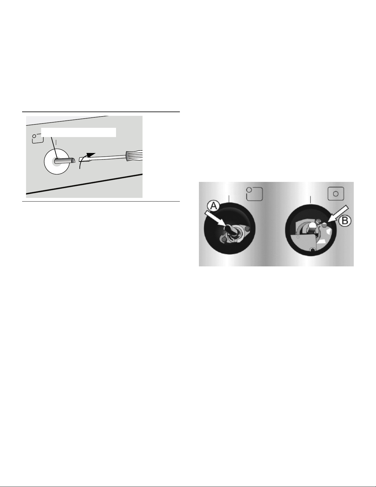
3. Locate the bypass screw (see illustration below).
Single valve stems are hollow; the bypass screw is
located inside the stem (A). Dual valves have a brass
adjustment screw (B) on the valve housing.
4. For single valves, insert 1/8” (or smaller) flat head
screwdriver into shaft and turn bypass screw clockwise
until it stops (bypass screw is inside shaft). DO NOT
OVERTIGHTEN. For dual valves, locate the brass
screw near the valve stem. Turn bypass screw
clockwise until it stops. DO NOT OVERTIGHTEN.
5. Replace the knob.
Adjust The Low Flame Setting
1. With at least two other burners lit, light the burner to be
adjusted and turn the knob to “LOW”.
2. As in the preceding procedure, remove the knob and
insert a screwdriver into the valve shaft.
3. Turn the adjustment screw until the flame is
appropriate for a LOW setting.
4. Replace the knob.
5. Repeat for each of the other burners.
For gas range conversions, continue to “Adjust Broil
Burner Orifice”. For dual-fuel ranges, continue to “Test
the Installation”.
English 5
Adjust Broil Burner Orifice
Adjust Bake Burner Orifice
1. Remove oven door (See section "Removing Oven
Door" in Use and Care Manual).
2. Remove Broil Burner Assembly. The broil burner
assembly is attached to the top of the oven cavity with
5 screws. Remove screws and gently pull broil burner
assembly straight out being careful not to detach
electrical wires. Place broil burner against back wall of
oven cavity.
3. Use 1/2 inch (13 mm) wrench to remove the natural
gas orifice and install the separate LP gas orifice
provided. The orifice is located inside the oven cavity at
the top right (visible with burner assembly removed.)
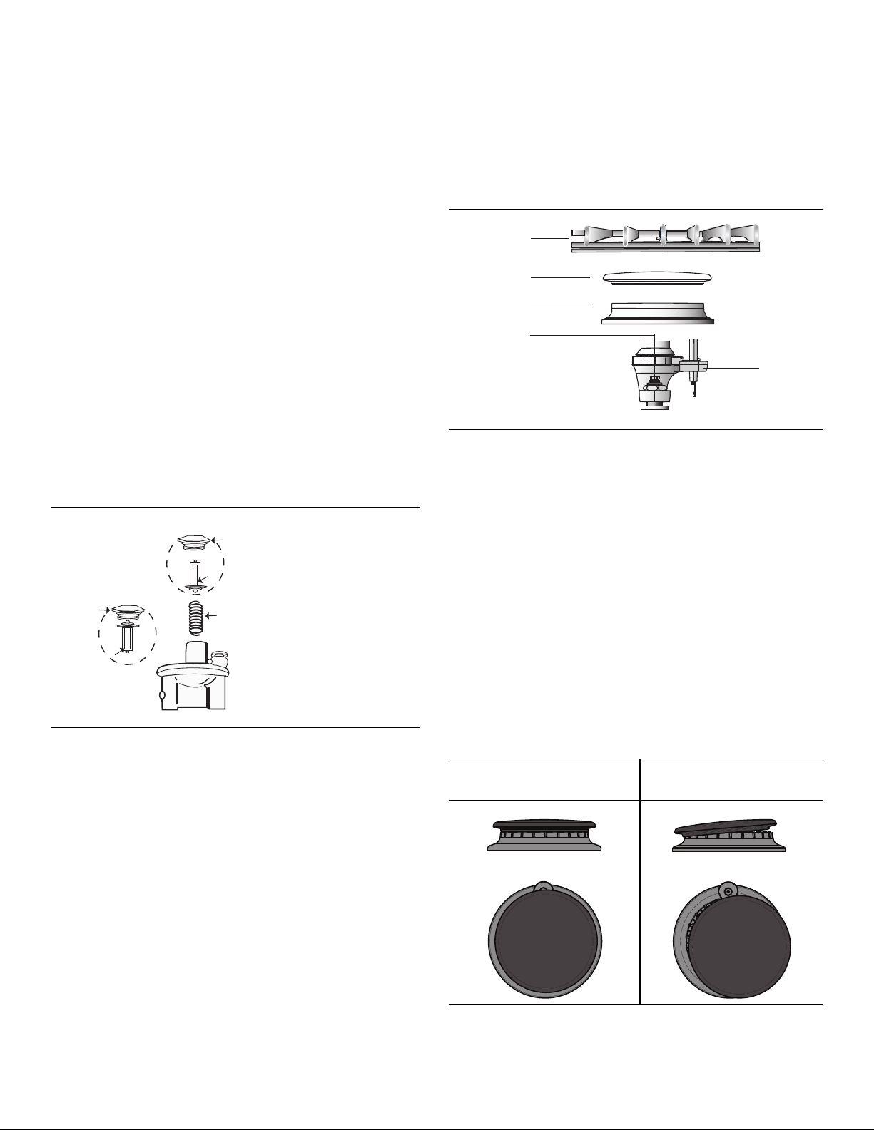
The bake burner orifice is located below the air shutter
(See Figure 3). Reach it through the access hole in the
interior back panel of the warming drawer cavity.
1. Use a 1/2" wrench to turn orifice clockwise until it stops
(2 1/2 - 3 turns). Unlike the broil burner orifice, the
bake burner orifice should be tightened as far as it will
go in order to ensure that complete conversion has
occurred.
Air Shutter
Bake Orifice
Figure 3: Bake Burner Orifice Adjustment
2. Use a Phillips head screwdriver to loosen the screw in
the bake burner air shutter. Once loosened, turn the air
shutter to its widest position (see figure below). Tighten
the Phillips head screw in the air shutter.
4. Use a Phillips head screwdriver to loosen the screw in
broil burner air shutter. Once loosen, take the LP
conversion jig and place the THINNEST cylinder into
the air shutter. Turn air shutter until it fits tightly against
the pin. Tighten the Phillips screw in the air shutter and
remove the LP conversion jig. DO NOT LEAVE LP
CONVERSION JIG IN AIR SHUTTER
Note: The air shutter on the broil burner fits over the orifice
when installed correctly.
English 6
Test the Installation
Test for Gas Leaks
9 CAUTION
Never check for leaks with a flame.
Leak testing is to be conducted by the installer according to
the instructions given in this section.
Apply Leak Detection Fluid
Turn on gas. Apply a non-corrosive leak detection fluid to
all joints and fittings in the gas connection between the
shutoff valve and the range. Include gas fittings and joints
in the range if connections may have been disturbed during
installation. Bubbles appearing around fittings and
connections indicate a leak.
If a leak appears, turn off supply line gas shutoff valve and
tighten connections. Retest for leaks by reapplying a noncorrosive leak detection fluid and then turn on the supply
line gas shutoff valve. When leak check is complete (no
bubbles appear), test is complete. Wipe off all detection
fluid residue.
Do not continue to the next step until all leaks are
eliminated.
Test Electric Ignition
Test Flame Characteristics on the Low Setting
1. Push in and turn the knob to the ignition symbol until
the burner ignites.
2. Turn knob to the low setting.
3. Verify that the burner maintains a minimum, steady,
flame without going out. The flame should not lift or
blow off of the burner. It should carry over, or surround,
the entire burner.
4. Verify that the flame is the right color. It should be blue
with an inner and outer cone. See Figure 4 “Checking
Flame Characteristics” for more information.
5. Test each rangetop burner in this fashion. If any flame
goes out, does not carry over properly or is too large,
contact Service.
Test Flame Characteristics on the High Setting
1. Push in and turn the knob to the ignitor symbol until the
burner ignites.
2. Turn knob to the high setting.
3. Verify that the burner maintains a steady flame. The
flame should not lift or blow off of the burner. It should
carry over, or surround, the entire burner.
4. Verify that the flame is the right color. It should be blue
with an inner and outer cone. See Figure 4: “Checking
Flame Characteristics” for more information.
5. Test each rangetop burner in this fashion.
If any flame goes out, does not carry over properly or is too
large, contact Service.
Turn on power at breaker.
Caution: If the display flashes and beeps, the polarity of
the wiring may be reversed. Reversed polarity can damage
the range and can be an electrical shock hazard.
Immediately switch off power at the breaker and return to
installation instructions.
Test Cooktop Burners
Each burner must be tested for proper lighting, proper
flame characteristics on the low setting and proper flame
characteristics on the high setting.
Test for Proper Ignition
1. Push down and turn the knob to ignition symbol.
2. Verify that the ignitor/spark module clicks.
3. Once the air has been purged from the supply lines,
verify that the burner lights within four (4) seconds.
After burner lights, turn knob to the off position.
4. Test each rangetop burner in this fashion. Call Service
if any of the burners do not light.
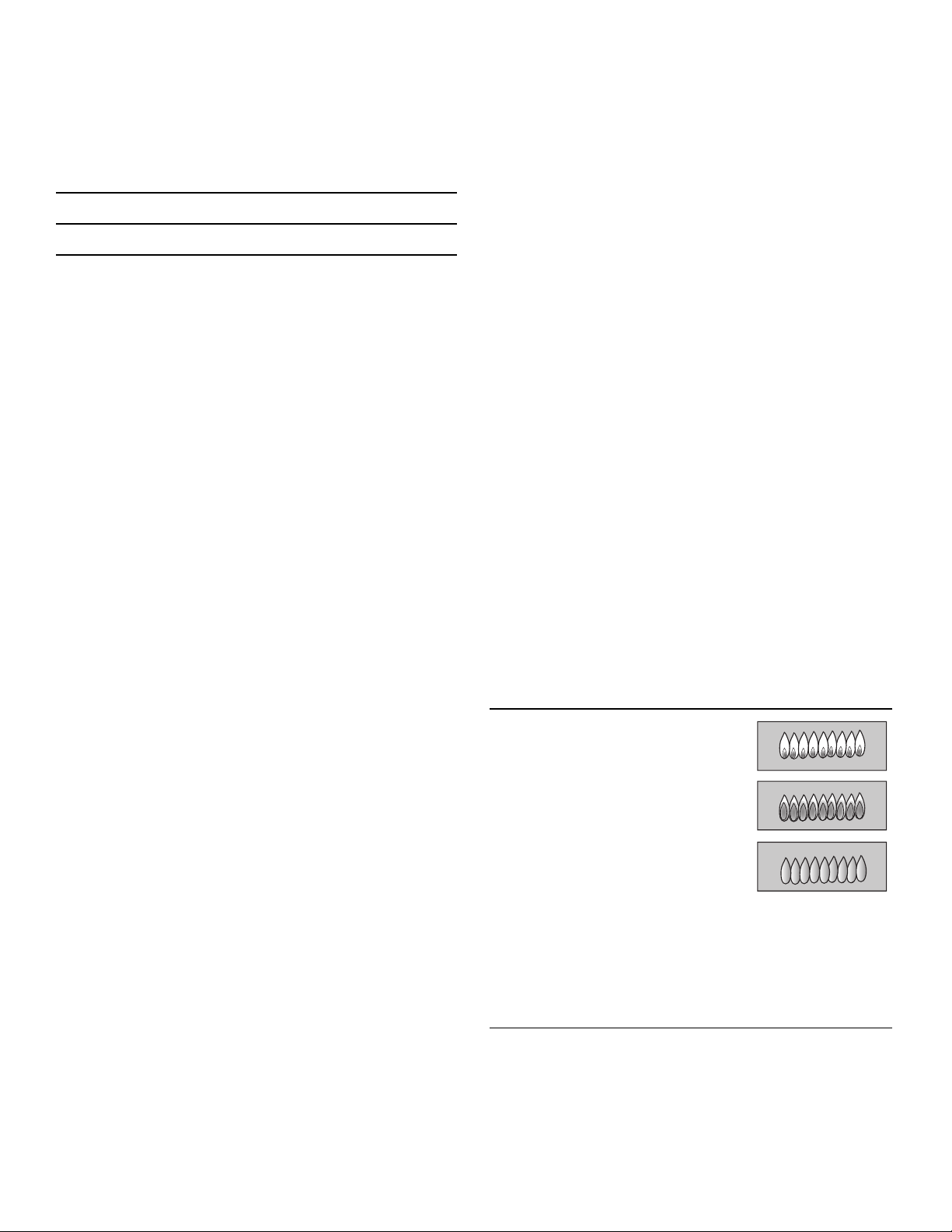
Yellow Flames:
Further adjustment is required.
Yellow Tips on Outer Cones:
Normal for LP Gas.
Soft Blue Flames:
Normal for Natural Gas.
If the flame is completely or mostly
yellow, verify that the regulator is set for the correct fuel.
After adjustment, retest.
Some yellow streaking is normal during the initial
start-up. Allow unit to operate 4-5 minutes and reevaluate before making adjustments.
Figure 4: Checking Flame Characteristics
If any flame does not carry over properly, adjust the bypass
jet. Return to “Convert Cooktop Valves for Propane Use”
on page 5. If any flame burns yellow, contact Service.
English 7
Dual Fuel appliance installation is complete when correct color, carryover and size are verified on each
cooktop burner.
For gas appliances, continue to “Test Broil Burner”.
Test Broil Burner
Test Ignition
Set cooking mode to Hi Broil. The burner will ignite after
30-75 seconds.
Test Flame
Verify that flame characteristics are as shown in Figure 4
“Checking Flame Characteristics”. If flame characteristics
are not consistent with those in the graphic above, adjust
the flame as described below. Otherwise, continue to “Test
Bake Burner”.
Adjust Broil Flame (if necessary)
Test Bake Burner
Test Ignition
Set the oven to bake at 350° F (176.67°C). After 30-75
seconds, the burner will ignite. The burner will stay lit until
the 350° F (176.67°C) is reached and then shut off. From
this point forward, the burner will cycle on and off to
maintain the temperature.
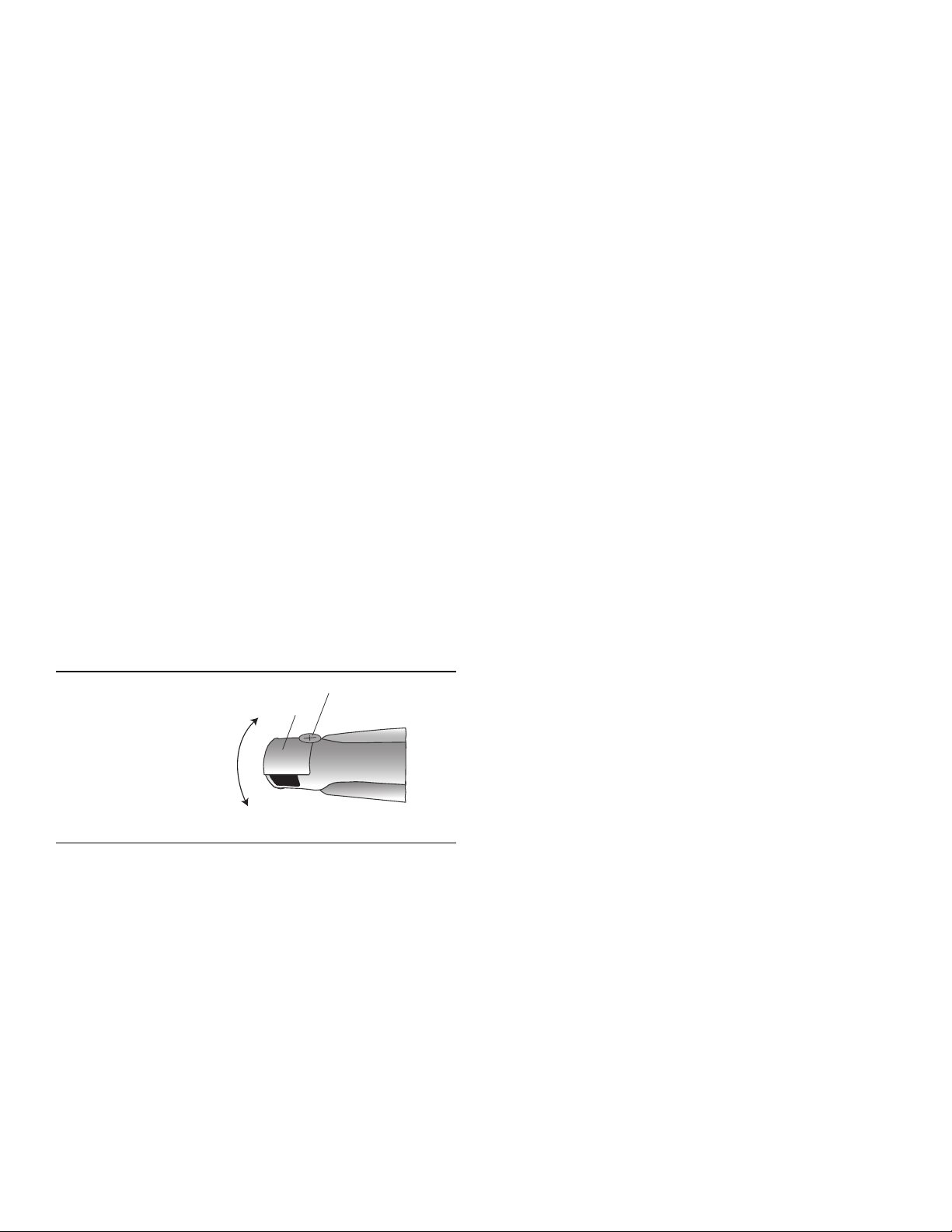
Adjust the air shutter to alter the flame characteristics. The
air shutter is located on the back end of the broil burner.
1. Loosen screw and turn shutter. Close the shutter if the
flame is lifting or blowing or not carrying over; open the
shutter if it is too yellow. (See Figure 5). Tighten screw.
Screw
More Open:
Less Yellow Flame
More Closed:
Less Blue Flame
More Carryover
Less Lifting or Blowing
Figure 5: Broil Air Shutter Adjustment
Air
Shutter
English 8
 Loading...