


Industrial PC
CPS21_3 / CPS21_4
Interface Conditions
Antriebs- und Steuerungstechnik
Edition
103

Industrial PC
CPS21_3 / CPS21_4
Interface Conditions
1070 073 825-103 (02.04) GB
E 1999 – 2002
by Bosch Rexroth AG, Erbach / Germany
All rights reserved, including applications for protective rights.
Reproduction or distribution by any means subject to our prior written permission.
Discretionary charge 6.–

Contents
Contents
1 Safety Instructions 1–1 . . . . . . . . . . . . . . . . . . . . . . . . . . . .
1.1 Proper use 1–1 . . . . . . . . . . . . . . . . . . . . . . . . . . . . . . . . . . . . . . . . . . . . .
1.2 Qualified personnel 1–3 . . . . . . . . . . . . . . . . . . . . . . . . . . . . . . . . . . . . . .
1.3 Safety markings on products 1–4 . . . . . . . . . . . . . . . . . . . . . . . . . . . . . .
1.4 Safety instructions in this manual 1–5 . . . . . . . . . . . . . . . . . . . . . . . . . .
1.5 Safety instructions for the product described 1–6 . . . . . . . . . . . . . . .
1.6 Documentation, software release and trademarks 1–8 . . . . . . . . . . .
2 System Overview CPS21_3 / CPS21_4 2–1 . . . . . . . . . .
2.1 Components 2–1 . . . . . . . . . . . . . . . . . . . . . . . . . . . . . . . . . . . . . . . . . . . .
2.2 Technical Data 2–5 . . . . . . . . . . . . . . . . . . . . . . . . . . . . . . . . . . . . . . . . . .
2.3 Software 2–6 . . . . . . . . . . . . . . . . . . . . . . . . . . . . . . . . . . . . . . . . . . . . . . .
2.4 Expansion Cards 2–7 . . . . . . . . . . . . . . . . . . . . . . . . . . . . . . . . . . . . . . . .
2.4.1 BIOS Setup 2–8 . . . . . . . . . . . . . . . . . . . . . . . . . . . . . . . . . . . . . . . . . . . .
2.5 Rechargeable Battery Pack 2–9 . . . . . . . . . . . . . . . . . . . . . . . . . . . . . . .
2.6 Operating Conditions 2–11 . . . . . . . . . . . . . . . . . . . . . . . . . . . . . . . . . . . .
2.7 Applicable Standards 2–12 . . . . . . . . . . . . . . . . . . . . . . . . . . . . . . . . . . . .
V
Page
3 Safety Functions 3–1 . . . . . . . . . . . . . . . . . . . . . . . . . . . . . .
3.1 Temperature Monitoring 3–1 . . . . . . . . . . . . . . . . . . . . . . . . . . . . . . . . . .
3.2 Function of Uninterruptible Power Supply (UPS) 3–2 . . . . . . . . . . . .
3.3 UPS Program 3–4 . . . . . . . . . . . . . . . . . . . . . . . . . . . . . . . . . . . . . . . . . . .
3.3.1 Function 3–4 . . . . . . . . . . . . . . . . . . . . . . . . . . . . . . . . . . . . . . . . . . . . . . .
3.3.2 Operation 3–5 . . . . . . . . . . . . . . . . . . . . . . . . . . . . . . . . . . . . . . . . . . . . . .
3.3.3 Parameter settings 3–7 . . . . . . . . . . . . . . . . . . . . . . . . . . . . . . . . . . . . . .
4 Installation 4–1 . . . . . . . . . . . . . . . . . . . . . . . . . . . . . . . . . . .
4.1 Installation Positions and Clearances 4–2 . . . . . . . . . . . . . . . . . . . . . .
4.2 Dimensioned Drawing 4–4 . . . . . . . . . . . . . . . . . . . . . . . . . . . . . . . . . . .
4.3 Installation with Tip/Tilt Adapter 4–5 . . . . . . . . . . . . . . . . . . . . . . . . . . .
4.4 Installation of the optional Coolkit 4–6 . . . . . . . . . . . . . . . . . . . . . . . . . .
5 Electrical Connections 5–1 . . . . . . . . . . . . . . . . . . . . . . . .
5.1 Protective Earth Conductor (PE) and Screening Information 5–2 . .
5.2 Interference Suppression Information 5–3 . . . . . . . . . . . . . . . . . . . . . .
5.3 Supply Voltage 5–5 . . . . . . . . . . . . . . . . . . . . . . . . . . . . . . . . . . . . . . . . . .
5.3.1 24 VDC Supply 5–5 . . . . . . . . . . . . . . . . . . . . . . . . . . . . . . . . . . . . . . . . .
1070 073 825-103 (02.04) GB

VI
Contents
6 Interfaces and Connections 6–1 . . . . . . . . . . . . . . . . . . .
6.1 Overview 6–1 . . . . . . . . . . . . . . . . . . . . . . . . . . . . . . . . . . . . . . . . . . . . . . .
6.2 Position of Interfaces 6–2 . . . . . . . . . . . . . . . . . . . . . . . . . . . . . . . . . . . .
6.3 Connection and Distribution Card 6–4 . . . . . . . . . . . . . . . . . . . . . . . . .
6.4 Connection of the optional Coolkit to the Connection and Distribution
Card 6–7 . . . . . . . . . . . . . . . . . . . . . . . . . . . . . . . . . . . . . . . . . . . . . . . . . . .
6.5 Floppy Disk Connection 6–9 . . . . . . . . . . . . . . . . . . . . . . . . . . . . . . . . . .
6.6 COM1 through COM4 Serial Ports, USB 6–11 . . . . . . . . . . . . . . . . . . .
6.6.1 Pin Assignment 6–11 . . . . . . . . . . . . . . . . . . . . . . . . . . . . . . . . . . . . . . . . .
6.6.2 Settings 6–14 . . . . . . . . . . . . . . . . . . . . . . . . . . . . . . . . . . . . . . . . . . . . . . . .
6.7 LPT1 Parallel Port 6–15 . . . . . . . . . . . . . . . . . . . . . . . . . . . . . . . . . . . . . . .
6.7.1 Parallel Port for CD-ROM 6–16 . . . . . . . . . . . . . . . . . . . . . . . . . . . . . . . .
6.8 Ethernet Connector 6–17 . . . . . . . . . . . . . . . . . . . . . . . . . . . . . . . . . . . . . .
6.9 VGA Video Port 6–18 . . . . . . . . . . . . . . . . . . . . . . . . . . . . . . . . . . . . . . . . .
6.10 Keyboard ports 6–20 . . . . . . . . . . . . . . . . . . . . . . . . . . . . . . . . . . . . . . . . .
6.11 Mouse Port 6–21 . . . . . . . . . . . . . . . . . . . . . . . . . . . . . . . . . . . . . . . . . . . . .
6.12 DP-Slave Port 6–22 . . . . . . . . . . . . . . . . . . . . . . . . . . . . . . . . . . . . . . . . . .
6.13 24 V out Port 6–22 . . . . . . . . . . . . . . . . . . . . . . . . . . . . . . . . . . . . . . . . . . .
6.14 Expansion Card Interfaces 6–23 . . . . . . . . . . . . . . . . . . . . . . . . . . . . . . .
6.14.1 PCI_BM-xxx Card 6–23 . . . . . . . . . . . . . . . . . . . . . . . . . . . . . . . . . . . . . . .
6.14.2 PCI_CAN Card 6–26 . . . . . . . . . . . . . . . . . . . . . . . . . . . . . . . . . . . . . . . . .
7 Display and Control Elements 7–1 . . . . . . . . . . . . . . . . .
7.1 Display 7–3 . . . . . . . . . . . . . . . . . . . . . . . . . . . . . . . . . . . . . . . . . . . . . . . .
7.1.1 Backlight Function 7–3 . . . . . . . . . . . . . . . . . . . . . . . . . . . . . . . . . . . . . . .
7.2 Keyboard 7–5 . . . . . . . . . . . . . . . . . . . . . . . . . . . . . . . . . . . . . . . . . . . . . .
7.2.1 Blocks of Function Keys 7–5 . . . . . . . . . . . . . . . . . . . . . . . . . . . . . . . . . .
7.2.2 Key Blocks ”Control” 7–6 . . . . . . . . . . . . . . . . . . . . . . . . . . . . . . . . . . . . .
7.2.3 Key Block ”Machine” 7–6 . . . . . . . . . . . . . . . . . . . . . . . . . . . . . . . . . . . . .
7.2.4 Number, Cursor Control and Special Keys Blocks 7–7 . . . . . . . . . . .
7.2.5 Key Mouse 7–8 . . . . . . . . . . . . . . . . . . . . . . . . . . . . . . . . . . . . . . . . . . . . .
7.3 LED Indicators 7–9 . . . . . . . . . . . . . . . . . . . . . . . . . . . . . . . . . . . . . . . . . .
7.3.1 Hardware Indicators 7–9 . . . . . . . . . . . . . . . . . . . . . . . . . . . . . . . . . . . . .
7.3.2 Customer-Specific Indicators 7–10 . . . . . . . . . . . . . . . . . . . . . . . . . . . . .
7.4 Front Panel Labeling 7–11 . . . . . . . . . . . . . . . . . . . . . . . . . . . . . . . . . . . .
7.5 Keyboard Controller 7–13 . . . . . . . . . . . . . . . . . . . . . . . . . . . . . . . . . . . . .
7.5.1 Scanning of Front Panel Keyboard 7–13 . . . . . . . . . . . . . . . . . . . . . . . .
7.5.2 Exceptions for Simultaneously Pressed Keys 7–18 . . . . . . . . . . . . . . .
7.5.3 User-Defined Assignment of Key Codes 7–18 . . . . . . . . . . . . . . . . . . .
7.5.4 Software Download for Keyboard Controller 7–18 . . . . . . . . . . . . . . . .
8 Maintenance and Replacements 8–1 . . . . . . . . . . . . . . .
8.1 Maintenance 8–1 . . . . . . . . . . . . . . . . . . . . . . . . . . . . . . . . . . . . . . . . . . .
8.2 Replacements 8–2 . . . . . . . . . . . . . . . . . . . . . . . . . . . . . . . . . . . . . . . . . .
8.2.1 Hard Disk 8–2 . . . . . . . . . . . . . . . . . . . . . . . . . . . . . . . . . . . . . . . . . . . . . .
8.2.2 Display and Backlight/Inverter 8–5 . . . . . . . . . . . . . . . . . . . . . . . . . . . .
8.2.3 Rechargeable Battery Pack 8–7 . . . . . . . . . . . . . . . . . . . . . . . . . . . . . . .
9 Spare Parts 9–1 . . . . . . . . . . . . . . . . . . . . . . . . . . . . . . . . . . .
A Appendix A–1 . . . . . . . . . . . . . . . . . . . . . . . . . . . . . . . . . . . . .
A.1 Abbreviations A–1 . . . . . . . . . . . . . . . . . . . . . . . . . . . . . . . . . . . . . . . . . . .
A.2 Keyword index A–2 . . . . . . . . . . . . . . . . . . . . . . . . . . . . . . . . . . . . . . . . . .
1070 073 825-103 (02.04) GB

1 Safety Instructions
Before you start working with the Bosch CPS21_3 or CPS21_4 PC control,
we recommend that you thoroughly familiarize yourself with the contents of
this manual. Keep this manual in a place where it is always accessible to all
users.
1.1 Intended use
This manual contains information required for the proper use of this product.
However, for reasons of structural clarity, the manual cannot provide exhaustive details regarding all available combinations of functional options.
Similarly, it is feasible to consider every conceivable integration or operating
scenario within the confines of this manual.
Safety Instructions
1–1
The described industrial PCs serve as operating and visualization units
for Bosch proprietary application software running on Microsoft Windows 95
or Microsoft Windows NT 4.0 operating systems. They are intended as control platforms for testing, adjustment and assembly station applications.
While it is possible in principle to operate other proprietary operating systems or application software on the industrial PCs, the occurrence of unexpected effects, even with Bosch applications, cannot be entirely ruled out.
With this type of nonstandard operation, Bosch shall not assume any liability
for either hardware and/or software.
The products described hereunder
D were developed, manufactured, tested and documented in accordance
with the relevant safety standards. In standard operation, and provided
that the specifications and safety instructions relating to the project
phase, installation and correct operation of the product are followed,
there should arise no risk of danger to personnel or property.
D are certified to be in full compliance with the requirements of the
D COUNCIL DIRECTIVE 89/336/EEC of May 3rd 1989 on the approx-
imation of the laws of the Member States relating to electromagnetic
compatibility, 93/68/EEC (amendments of Directives), and
93/44/EEC (relating to machinery)
D COUNCIL DIRECTIVE 73/23/EEC (electrical equipment designed for
use within certain voltage limits)
D Harmonized standards EN 50081-2 and EN 50082-2
D are designed for operation in an industrial environment (Class A
emissions). The following restrictions apply:
D No direct connection to the public low-voltage power supply is per-
mitted.
D Connection to the medium and/or high-voltage system must be pro-
vided via transformer.
The operation of Class A devices in private residences, in business or
small-industry settings is permitted only if their operation does not produce undue interference with other devices.
1070 073 825-103 (02.04) GB
. This is a Class A device. In a residential area, this device may cause
radio interference. In such case, the user may be required to introduce
suitable countermeasures, and to bear the cost of the same.

1–2
Safety Instructions
Proper transport, handling and storage, placement and installation of the
product are indispensable prerequisites for its subsequent flawless service
and safe operation.
1070 073 825-103 (02.04) GB

1.2 Qualified personnel
Safety Instructions
1–3
This instruction manual is designed for specially trained personnel. The relevant requirements are based on the job specifications as outlined by the
ZVEI and VDMA professional associations in Germany. Please refer to the
following German-Language publication:
Weiterbildung in der Automatisierungstechnik
Publishers: ZVEI and VDMA Maschinenbau Verlag
Postfach 71 08 64
60498 Frankfurt/Germany
The present manual is designed for engineering personnel and PC specialists. These persons need special knowledge of the configuration and
commissioning of electrical equipment.
Interventions in the hardware and software of our products not described in
this instruction manual may only be performed by our skilled personnel.
Unqualified interventions in the hardware or software or non-compliance
with the warnings listed in this instruction manual or indicated on the product
may result in serious personal injury or damage to property.
Installation and maintenance of the products described hereunder is the exclusive domain of trained electricians as per IEV 826-09-01 (modified) who
are familiar with the contents of this manual.
Trained electricians are persons of whom the following is true:
D They are capable, due to their professional training, skills and expertise,
and based upon their knowledge of and familiarity with applicable technical standards, of assessing the work to be carried out, and of recognizing
possible dangers.
D They possess, subsequent to several years’ experience in a comparable
field of endeavour, a level of knowledge and skills that may be deemed
commensurate with that attainable in the course of a formal professional
education.
With regard to the foregoing, please read the information about our comprehensive training program. The professional staff at our training centre will
be pleased to provide detailed information. You may contact the centre by
telephone at (K49) 6062 78-600.
1070 073 825-103 (02.04) GB

1–4
Safety Instructions
1.3 Safety markings on components
DANGER! High voltage!
DANGER! Corrosive battery acid!
CAUTION! Electrostatically sensitive components!
Disconnect mains power before opening!
Lug for connecting PE conductor only!
Screened conductor only!
1070 073 825-103 (02.04) GB

1.4 Safety instructions in this manual
DANGEROUS ELECTRICAL VOLTAGE
This symbol warns of the presence of a dangerous electrical voltage. Insufficient of lacking compliance with this warning can result in personal
injury.
DANGER
This symbol is used wherever insufficient or lacking observance of this instruction can result in personal injury.
Safety Instructions
1–5
CAUTION
This symbol is used wherever insufficient or lacking observance of instructions can result in damage to equipment or data files.
. This symbol is used to alert the user to an item of special interest.
L This asterisk symbol indicates that the manual is describing an activity which
the user will be required to perform.
1070 073 825-103 (02.04) GB

1–6
Safety Instructions
1.5 Safety instructions for the described product
DANGER
Fatal injury hazard through ineffective Emergency-OFF devices!
Emergency-OFF safety devices must remain effective and accessible during all operating modes of the system. The release of functional locks imposed by Emergency-OFF devices must never be allowed to cause an uncontrolled system restart! Before restoring
power to the system, test the Emergency-OFF sequence!
DANGER
Retrofits or modifications may interfere with the safety of the products described hereunder!
The consequences may be severe personal injury or damage to
equipment or the environment. Therefore, any system retrofitting or
modification utilizing equipment components from other manufacturers will require express approval by Bosch.
DANGEROUS ELECTRICAL VOLTAGE
Unless described otherwise, maintenance procedures must always
be carried out only while the system is isolated from the power supply. During this process, the system must be blocked to prevent an
unauthorized or inadvertent restart.
If measuring or testing procedures must be carried out on the active
system, these must be carried out by trained electricians.
CAUTION
Only Bosch-approved spare parts may be used!
CAUTION
Danger to the module!
All ESD protection measures must be observed when using the
module! Prevent electrostatic discharges!
1070 073 825-103 (02.04) GB

Safety Instructions
1–7
Observe the following protective measures for electrostatically endangered
modules (EEM)!
D The Employees responsible for storage, transport and handling must be
trained in ESD protection.
D EEMs must be stored and transported in the protective packaging speci-
fied.
D Out of principle, EEMs may be handled only at special ESD work stations
equipped for this particular purpose.
D Employees, work surfaces and all devices and tools that could come into
contact with EEMs must be on the same potential (e.g. earthed).
D An approved earthing wrist strap must be worn. It must be connected to
the work surface via a cable with integrated 1 MW resistor.
D EEMs may under no circumstances come into contact with objects sus-
ceptible to accumulating an electrostatic charge. Most items made of
plastic belong to this category.
D When installing EEMs in or removing them from an electronic device, the
power supply of the device must be switched OFF.
1070 073 825-103 (02.04) GB

1–8
Safety Instructions
1.6 Documentation, software release and trademarks
Documentation
The present manual contains information on technical data, the operation
and configuration of the CPS21_3 / CPS21_4 PC control.
Overview of available documentation Part no.
English German
Release
Trademarks
CPS21_3 / CPS21_4 PC control
Interface conditions
1070 073 825 1070 073 815
. In this manual the floppy disk drive always uses drive letter A:, and the
hard disk drive always uses drive letter C:.
Special keys or key combinations are shown enclosed in pointed brackets:
D Named keys: e.g. <Enter>, <PgUp>, <Del>
D Key combinations (pressed simultaneously): e.g. <Ctrl> + <PgUp>
. The software version of Windows NT may be displayed as follows:
1. Click with right mouse key on the ”My Computer” icon on your
desktop
2. Select menu item ”Properties”.
All trademarks referring to software that is installed on Bosch products when
shipped from the factory represent the property of their respective owners.
At the time of shipment from the factory, all installed software is protected by
copyright. Software may therefore be duplicated only with the prior permission of the respective manufacturer or copyright owner.
MS-DOSr and Windowst are registered trademarks of Microsoft Corporation.
PROFIBUSr
tion e.V. (user organization).
is a registered trademark of the PROFIBUS Nutzerorganisa-
1070 073 825-103 (02.04) GB

System Overview CPS21_3 / CPS21_4
2 System Overview CPS21_3 / CPS21_4
2.1 Components
The CPS21_3 / CPS21_4 control unit is a complete mechanical unit consisting of:
D closed aluminum housing with
D color LC Display (CPS21_3: 13,8”; CPS21_4: 15”),
D a membrane keyboard with additional operating and display devices and
D a built-in high performance industrial PC.
The CPS21_3 / CPS21_4 is distinguished by the following:
D being largely fail-safe (e.g. shock and vibration resistant hard disk s u s -
pension , UPS – uninterruptible power supply) and
D simple maintenance.
The standard operating system Windows NT 4.0 and the Bosch application
software are preinstalled on the CPS21_3 / CPS21_4 (see section 2.3).
2–1
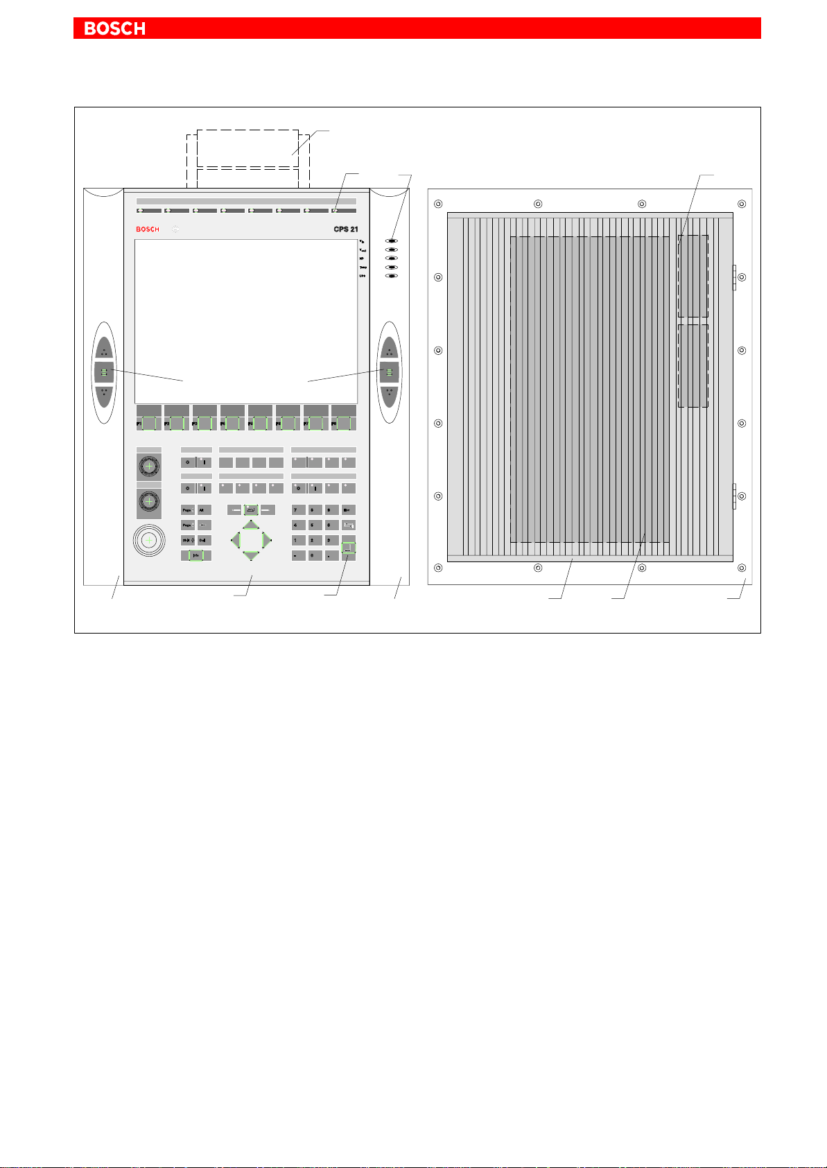
Front view CPS21_3
1070 073 825-103 (02.04) GB

2–2
System Overview CPS21_3 / CPS21_4
Front view CPS21_4
Housing:
The PC is completely covered by an anodized aluminum housing and is internally and externally equipped with cooling fins. Under the given operating
conditions (see section 2.6), this ensures passive
cooling for the integrated PC.
Frame and
Handles:
A plastic frame is connected to the housing by 2 hinges. A handlebar with three navigation buttons is fastened on each side – left and right – of the frame in
order to provide a user friendly operation. On its rear
side, the PC is fastened to the plastic frame.
Front panel: Display, membrane keyboard and the PC which, at its
rear side, is fixed to the plastic frame are fastened to
the front panel. If the frame and the front panel are
swung to the side, the display and the hard disk can
easily be replaced after the PC box has been removed (see section 8).
Insertionlabels:
Up to five labels are available for individual button
description.
Suspension: The entire unit is suitable for floor or suspended
mounting. (refer to section 4.3).
1070 073 825-103 (02.04) GB
System Overview CPS21_3 / CPS21_4
2–3
CPS21_3
13.8” Color TFT Display
Navigation keys
Tilt/tip adapter
LEDs
Battery
(internal)
Handle
Front panel
Keyboard
Handle
Aluminum housing
PC
(internal)
Plastic
frame
1070 073 825-103 (02.04) GB

2–4
System Overview CPS21_3 / CPS21_4
CPS21_4
15” Color TFT Display
Navigation keys
Tilt/tip adapter
LEDs
Battery
(internal)
Handle
Front panel
Keyboard
Handle
Aluminum housing
PC
(internal)
Plastic
frame
1070 073 825-103 (02.04) GB
2.2 Technical Data
System Overview CPS21_3 / CPS21_4
2–5
. All specifications are subject to change as a result of technological de-
velopments. This also means that components providing higher than
the specified performance (e.g. a faster processor) may be integrated
in the devices without explicit reference in this documentation.
Feature CPS21_3 / CPS21_4
Processor ≥ Intel Pentium 266 MHz with MMXT tech-
nology (socket 7) or compatible CPU
Second level cache 512 KB
Random Access Memory
(DIMM-modules)
Hard Disk ≥ 3.2 GB (IDE)
Display 13.8” Color-TFT (CPS21_3)
3 expansion slots PCI / ISA: 3 / 0 or 2 / 1,
Power supply 24 VDC
UPS (uninterruptible
power supply)
Interfaces
(for detailed information, refer to
Section 6)
Weight: approx. 18.8 kg (without adapter)
Dimensions Housing external:509 x 432 x 177 mm
128 MB SDRAM
or 15” Color-TFT
with non–reflecting and scratch–resistant
front screen
ex works including 2 PCI cards
via integrated rechargeable battery pack
(2 series-connected 6 V battery packs)
4 x serial,
1x parallel,
PS/2-keyboard and mouse
Ethernet,
USB,
key codes via 24 V out
2 x CAN bus and 1 x busmaster
(via expansion slots)
(CPS21_4)
1070 073 825-103 (02.04) GB
PC housing: 448 x 195 x 101 mm
Front panel: 499.5 x 409.5 x 5 mm
Operating system Windows NT4.0

2–6
System Overview CPS21_3 / CPS21_4
2.3 Software
BIOS software
Operating system
. For subsequent loading of software and for data backup, a floppy disk
drive or the connection to an Ethernet network is necessary . The drive
can be purchased separately.
The BIOS software is licensed by Phoenix. With the BIOS software, the PC
boots until it finds an operating system that provides a more convenient and
user–friendly platform for running the application software.
The BIOS setup must not be altered. It is documented in the manual ”BT150,
BT200, BT250, CPS21_3 Software Configuration”.
The CPS21_3 / CPS21_4 has been equipped and tested with the following
operating systems from Microsoft Corp.:
D Windows NT (version 4.0), including possibly necessary NT service re-
leases from Microsoft Corp.
Utility programs
Application software
Additionally, the following utility program is installed:
D UPS
– Uninterruptible Power Supply Program for Windows NT
NT
(is not part of the Windows NT operating system software).
The following optional Bosch software is available:
Application CPS21_3 / CPS21_4
PCL Software PLC •
MMI-Madap Software for control and diagnosis of
plant
WinSPS PLC programming software on request
WinCan Fieldbus parameter assignment for CAN bus on request
TSWIN Programming interface for
operating terminals
• = available;
on request
on request
1070 073 825-103 (02.04) GB
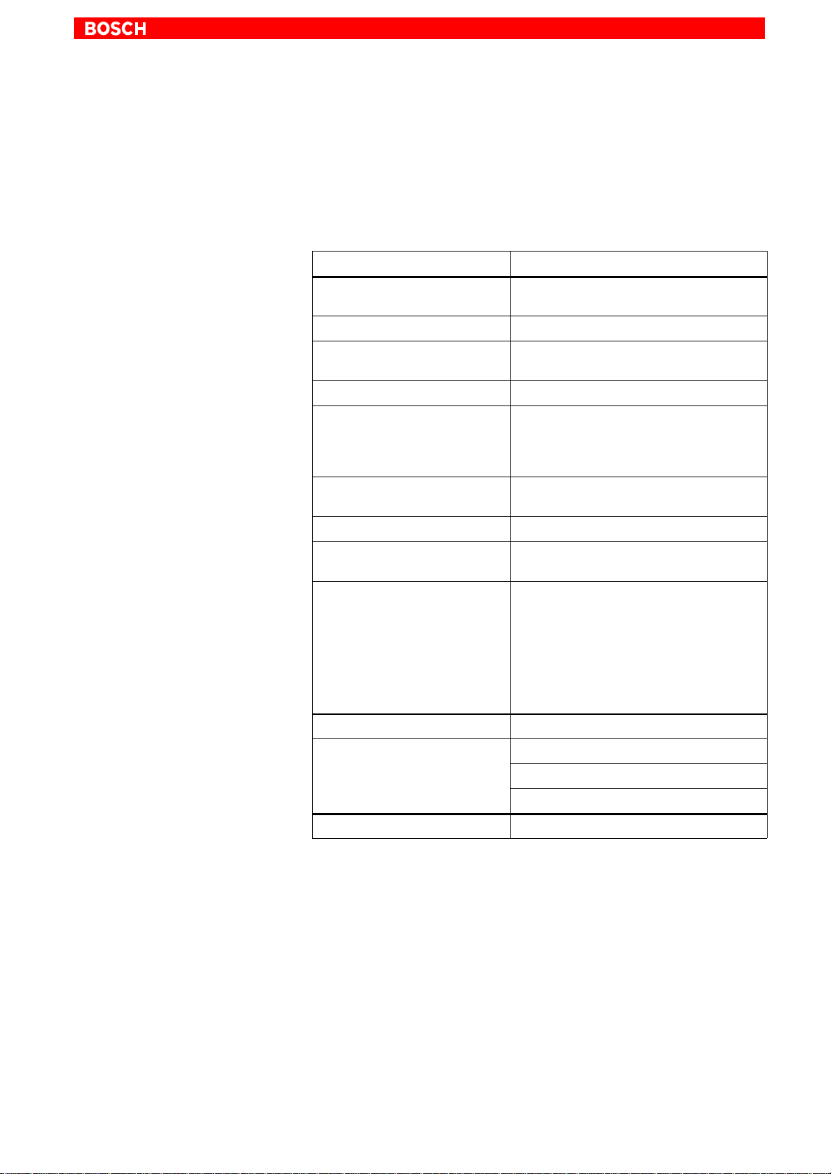
2.4 Expansion Cards
System Overview CPS21_3 / CPS21_4
2–7
The CPS21_3 / CPS21_4 has 3 slots for expansion cards with a maximum
length of 180 mm:
D 2 PCI BUS cards and
D 1 combination slot for 1 PCI or 1 ISA BUS card
Slot A1
Slot A2
must not be used if
PCI card is
inserted
Combination
slot A3
PCI bus slot
PCI bus slot
must not be used if
ISA card is inserted
ISA bus slot
PCI bus slot
CAUTION
Destruction of an expansion card or the motherboard!
PCI and ISA cards must never be inserted simultaneously in the PCI/
ISA-BUS combination slot!
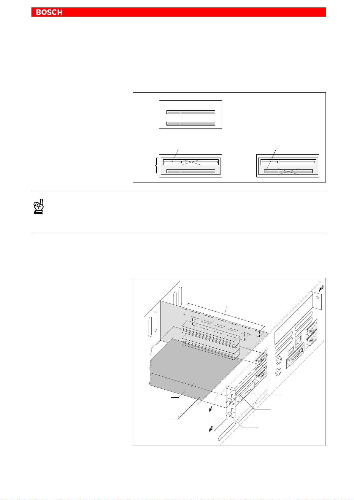
The following expansion cards are used in the CPS21_3 / CPS21_4:
D PCI-CAN card: – CAN bus interface
D PCI_BM-CAN card: – CAN bus interface
– busmaster interface
ISA/PCI combination slot A3
PCI-CAN
card (on A1)
PCI-BM_CAN
card (on A2)
. For interfaces, refer to section 6.14.2
Slot cover
PCI-CAN
Slot cover
PCI_BM-CAN
Screw for fastening
slot cover
1070 073 825-103 (02.04) GB

2–8
System Overview CPS21_3 / CPS21_4
2.4.1 BIOS Setup
PCI slot x
In order to use other expansion cards, a driver software that is recommended by the card manufacturer might be necessary.
CAUTION
Using unauthorized expansion cards may result in damage to the PC
and/or the application software.
Please use only approved expansion cards, and have them installed
by a specialist.
In the BIOS submenu called “The Advanced Menu / PCI Configuration sub
menu” you can assign the interrupt request (IRQ) address to a specific PCI
slot. At the same time, the number of the IRQ address also defines the priority . I f only PnP cards are used, then the BIOS setup ”AUTO” must be main-
tained.
BIOS selection:PCI IRQ line 1, PCI IRQ line 2, PCI IRQ line 3, PCI IRQ line 4
Option: Disabled, Auto, IRQ: 3, 4, 5, 7, 9, 10, 11, 12, 14, 15,
Default: AUTO
ISA slot (IRQ)
ISA slot (UMB)
In the BIOS submenu ”The Advanced Menu / PCI Configuration sub menu /
PCI/PNP ISA IRQ Resource Exclusion / IRQx”, the IRQ Address for Legacy
ISA cards (ISA cards without plug-and-play capability) can be assigned per-
manently.
BIOS selection: IRQ:3, 4, 5, 7, 9, 10, 11, 15
Option: Available, Reserved
Default: Available
In the BIOS menu “The Advanced Menu / PCI Configuration sub menu /PCI/
PNP ISA UMB Region Exclusion” you can reserve a specific upper memory
block for Legacy ISA cards (without ”plug–and–play” capability) .
BIOS selection: C800 - CBFF, CC00 - CFFF, D000 - D3FF, D400 - D7FF,
D800 - DBFF, DC00 - DFFF
Option: Available, Reserved
Default: Available
CAUTION
Address conflicts (IRQ, memory access, I/O address) may cause
destruction of motherboard or ISA cards!
Please follow the instructions provided by the card manufacturer. I f
necessary you must make new configuration settings in the BIOS
and in the operating system (e.g. Windows NT control panel).
1070 073 825-103 (02.04) GB

2.5 Rechargeable Battery Pack
The CPS21_3 / CPS21_4 is equipped with a rechargeable battery pack
(composed of 2 series-connected 6V rechargeable batteries) that ensures a
controlled shutdown of the PC operating system by means of the uninterruptible power supply (UPS), in the event of a power failure. This prevents data
losses in the PC’s random access memory.
. UPS, refer to section 3
The rechargeable battery pack is located on the back of the front panel, next
to the PC in the aluminum housing. It is connected to the X19 connector on
the carrier board by a 2-conductor cable.
Charging function
During standard operation, the rechargeable battery pack is recharged by
means of a charging circuit. If the rechargeable battery pack (2.5 Ah) is absolutely empty, the charging process lasts 5 hours.
System Overview CPS21_3 / CPS21_4
2–9
Replacing the battery pack
The number of charging cycles that the rechargeable battery pack can withstand and therefore its useful life, depend on the ambient temperature in
which the battery pack is used. Ambient temperature here is defined as the
one in which the operating terminal is situated, e.g. the temperature in the
control cabinet or in the operating housing.
The following table can be used as a guideline:
Ambient temperature Charging cycles Maintenance interval
+ 25 °C 4000 cycles 6 years
+ 35 °C 2000 cycles 3 years
+ 45 °C 1000 cycles 1.5 years
. If there is some uncertainty concerning the temperature conditions of
the operating terminal, then we recommend exchanging the battery
pack every 1.5 years.
For position and replacement of installed battery, refer to section 8.2.3.
1070 073 825-103 (02.04) GB

2–10
System Overview CPS21_3 / CPS21_4
Charge level
With the UPSNT software program that can be called up via an icon on the
Windows NT status bar, a number of status data and settings related to the
UPS and battery operation can be read off (refer to section 3.3):
D Charging cycles: Number of previously performed charging
cycles (shutdown count).
D Checking the battery
charge level:
Presence of a rechargeable battery pack is
checked with each system startup (e.g. rechargeable battery pack not defective, no
cable break, positive plug contact)
D UPS interface: COM4
In case of an insufficient level of charge, it might be necessary to replace the
battery packs.
1070 073 825-103 (02.04) GB

2.6 Operating Conditions
The CPS21_3 / CPS21_4 is designed for continuous 24 hours/day operation. The display backlight can be switched off.
Unless stated otherwise in individual sections of this manual, the following
specifications apply:
Temperatures Storage temperature:
–20°C to +60°C
Ambient temperature: (outside the aluminum housing)
+5°C to +35°C (basic unit)
+5°C to +40°C (with external fan kit)
Ambient temperatures apply to installation conditions described in section 4.
Temperature fluctuations of up to 3°C per minute are permitted.
CAUTION
Excessive operating temperature!
Please do not expose the housing of the CPS21 to direct sunlight or
other sources of heat radiation!
System Overview CPS21_3 / CPS21_4
2–11
Humidity Climate class 3K3, to EN 60721, condensation not permitted.
Clearances and creeping distances In accordance with prEN50178 (11/96) at pollution level 2
Atmospheric pressure Operation at up to 2000 m above sea level, to DIN 60204
Degrees of Protection Front panel: IP 65, otherwise IP 54
Resistance ll surfaces are resistant to abrasion and media such as:
D Solvent naphtha (CH20V3)
D n-Heptane
D Test oil (VS15665)
D Hydraulic oil
D Lubricants
D Water
CAUTION
Conditions hazardous to the product!
The ambient air must be free of electrically conductive pollutants
(e.g., acids, alkali, corrosives, salts, metallic vapors, etc.).
Vibration resistance during operation
Frequency range: 10...150 Hz
Deflection: 0.075 mm at 10...57 Hz, according to EN 60068-2-6
Acceleration: 1 g with 57...150 Hz
Impact resistance 15 g, according to DIN IEC 68-2-27, no functional interruption
1070 073 825-103 (02.04) GB

2–12
System Overview CPS21_3 / CPS21_4
2.7 Applicable Standards
The CPS21 system components comply with the following standards:
D EN 60,204-1 Electrical systems on machines
D EN 50,081-2 Basic specification for interference emission
D EN 50 082-2 Basic technical standard, interference resistance
D EN 60,742 Tranformer for 24 V power supply, safety isolation
D EN 61,131 24 V output requirements
D EN 61,131-2 Requirements for 24 VDC power supply
D EN 418 Machine safety, EMERGENCY–OFF devices
D EN 60,529 Protection categories (incl. housings and installa-
D EN 60 721 Classification of environmental conditions
D EN 60 068-2-6 Vibration test
D EN 60068-2-27 Impact test
D .IS.114 X-ray radiation directive, as per Official Federal
(industrial environment)
(industrial environment)
tion compartments)
Gazette
. When leaving the plant, CPS21_3 / CPS21_4 complies fully with CE cer-
tification requirements.
However, the subsequent insertion of additional expansion cards will
necessitate a new CE certification.
1070 073 825-103 (02.04) GB

3 Safety Functions
3.1 Temperature Monitoring
The temperature inside the CPS21_3 / CPS21_4 must not exceed +45°C
(refer to section 2.6). For safety reasons, the PC features a temperature monitoring function that measures the temperature inside the aluminum housing.
If the temperature inside the housing exceeds +50°C, a temperature warning is issued:
D via the red flashing LED ”TEMP” on the front panel of the operating termi-
nal
D via a window displayed by the operating system.
This message must be interpreted by all application programs as well,
especially by I/O processes. Bosch application programs comply fully
with this requirement.
Safety Functions
3–1
The temperature warning function can be disabled via the program:
D UPS
If the temperature > inside the housing exceeds >65°C, the control
terminal is shut down and switched off via the UPS logic circuits (refer to
section 3.2).
for Windows NT 4.0 (refer to section 3.3).
NT
1070 073 825-103 (02.04) GB

3–2
Safety Functions
3.2 Function of Uninterruptible Power Supply (UPS)
In the event of a power failure or a temperature condition above 65 °C (refer
to section 3.1), the UPS logic circuit in the CPS21 power supply will facilitate
a safe shutdown of the PC operating system with the aid of the rechargeable
batteries.
Operating power will be drawn from rechargeable batteries (provided that
the batteries are working correctly) as soon as a voltage dip in excess of 20
ms has occurred.
. The UPS logic circuit of the CPS21 power supply is designed to ensure
the proper termination of all active application programs, followed by a
safe shutdown of the operating system. The UPS is not designed, however, to maintain the operation over a longer period of time!
DANGER
In the event that rechargeable batteries are found to be missing, defective or in a discharged condition, a voltage dip exceeding 20 ms
will trigger a RESET of the CPS21 without prior warning!
Possible consequences might be uncontrolled machine movements
and loss of data.
Users are advised to check the rechargeable batteries for proper
charge levels at regular intervals!
Power failure interval shorter than 800 ms
In the event that the mains power returns within the waiting interval of 800
ms, the power supply unit will again switch to standard operation.
V
Operating voltage
Operating voltage
restored within 800 ms
restored again
CPS21_3 is not shut down because
Operating
system
loaded
(standard
operation)
not loaded
interruption
of operating voltage is shorter than 800 ms
t0 t1 < 800 ms
t
t
1070 073 825-103 (02.04) GB

Power failure interval between 800 ms and 60 sec
A power failure interval exceeding 800 ms causes the operating system to
be shut down after a preset time (Delay Time). If the mains voltage returns
within 60 sec. the UPS will interrupt the operating voltage for an additional 8
sec. When point t3 has been reached, the operating system is again started
up.
Safety Functions
3–3
V
Operating voltage
Operating
system
loaded
(standard
operation)
not loaded
t0t1 = 800 ms
Mains voltage failure Mains voltage available
Shutdown of the
application program
Delay Time,
adjustable
Power failure interval exceeding 60 sec
When approx. 60 seconds have elapsed, the UPS will internally de-energize
the power supply.
Shutdown of the
operating system
< 60 sec
t
2
Operating
voltage
interrupted for
8 seconds
Operating
system startup
t
= t2 + 8 sec
3
t
t
Operating voltage
Operating
system
loaded
(standard
operation)
not loaded
V
Delay Time,
adjustable
t0t1 = 800 ms t4 = t1 + 60 sec
. Setting the Delay Time is done in the ”UPS
Mains voltage failure
Shutdown of the
application program
Shutdown of the
operating system
(Must not be restarted manually)
UPS de–energizes power supply
” software (refer to section
NT
t
t
3.3.2).
1070 073 825-103 (02.04) GB

3–4
Safety Functions
3.3 UPS Program
3.3.1 Function
The ”UPSNT” program (Uninterruptible Power Supply) serves to control and
monitor the integrated uninterruptible power supply. In addition, the program
checks the functioning of the rechargeable battery and controls the system’s
temperature monitoring function.
Program and UPS communicate via the COM4 serial port.
In case of a power failure, it is the UPS program’s task within a preset time
(Delay Time: max. 60 seconds)
D to provide a message to all active applications on the control terminal,
enabling them to be terminated either by the user or by means of special
application routines, and
D to shut down the operating system after expiration of the Delay Time.
When the voltage monitoring function has responded, the system shut
down can no longer be avoided.
Closing down all active applications prevents loss of data in case of sudden
power failure.
After a maximum of 60 seconds, the UPS shuts down the CPS21_3 /
CPS21_4 power supply unit if the mains voltage has not yet returned (refer to
section 3.2 Function of uninterruptible power supply).
CAUTION
Restarting the system manually leads to loss of data!
The UPS turns off the CPS21_3 / CPS21_4 in any case. Consequently
the dialog ”Restart” must not be activated after the shutdown of the
operating system.
In case of a voltage failure that lasts less than 60 seconds, the operating system restarts automatically.
During normal operation, the operator does not have access to the UPS
program. It can only be operated and parameterized by persons with special
administrator rights and after restart of the operating system.
. Modifications to the UPS
Bosch.
parameters require the prior consent of
NT
NT
1070 073 825-103 (02.04) GB
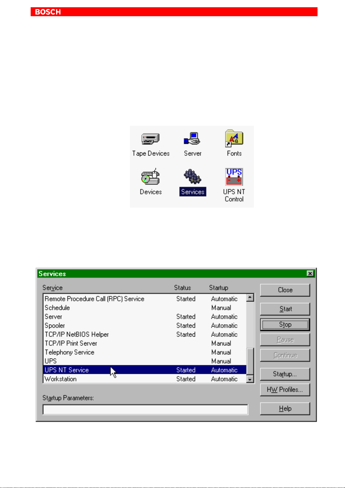
3.3.2 Operation
Start/Stop
Safety Functions
. Administrator rights are required for operation!
When starting Windows NT, the UPS
For interrupting, shutting down or restarting the service (e.g. for new installa-
tion or update), select ”Services” from the ”Control Panel” window (see the
following illustration, left of UPS
program is launched automatically.
NT
Control).
NT
3–5
In the Services window of Windows NT, the status of the UPSNT Service is
displayed:
D UPS
D UPS
Start and stop the selected entry UPS
stopped: Status column is empty
NT
started: Status column displays ”Started”
NT
Service with the Start and Stop but-
NT
tons, respectively.
1070 073 825-103 (02.04) GB

3–6
Safety Functions
Configuration
. The UPS
the user has no influence on this. A user without Administrator privileges is neither able to terminate the program nor to stop the monitoring
function.
In order to configure UPS
nel” window (see below).
The dialog ”UPS NT Configuration” determines the start and runtime behavior of UPS control.
The individual values of the configuration are stored in the Registry. The parameters can be changed at any time.
program always runs as a Windows NT service. Changing
NT
, select ”UPS NT Control” from the ”Control Pa-
NT
. After modifying the parameters, the UPS program must be stopped
and restarted in order to become operative.
This can be achieved by restarting the computer or with the help of the
Services manager.
. For details and parameter settings refer to section 3.3.3 .
1070 073 825-103 (02.04) GB

3.3.3 Parameter Settings
COM Port
UPS Shutdown Parameter
Shutdown Delay Time
Safety Functions
The UPS program is always connected to the UPS via the COM4 serial port.
Smart Shutdown
When the Power Down signal has been received from the UPS, the Delay
Time starts.
Here the time (0 to 60 seconds) for delaying the shutdown is entered. Wit-
hin this time frame, a request to close down is sent to all open windows. During this time, the user can save his data. When the Delay Time has expired,
all application programs are shut down without further notice!
3–7
Advanced Controls
When choosing the Delay Time, make sure that the time between the end of
the Delay Time and the end of the 60 seconds after the Power Down Signal is
long enough to shut down the operating system (close all Windows system
files and make backups). If the period of time chosen is too short, the shutdown process is interrupted because the UPS interrupts the power supply of
the CPS21_3 / CPS21_4. This might lead to data loss.
CAUTION
On expiry of the Delay Time, the operating system is shut down without further notice. Data from open application programs that has
not been backed up, is lost.
Enable Accu (i.e. Rechargeable Battery) Test
If this checkbox is activated, the system tests the rechargeable battery pack
with each new start.
In the case of a faulty battery pack (e.g. defective battery pack, cable break,
plug not connected), battery monitoring is disabled. The UPS program continues only with its temperature monitoring function.
If temperature monitoring is not activated, the UPS program is shut down.
1070 073 825-103 (02.04) GB
. A message that the rechargeable battery pack is empty is displayed.

3–8
Safety Functions
Enable Temp Control
If this checkbox is activated, the system temperature is monitored permanently. If the system temperature is exceeded, the following warning is displayed:
After a temperature warning, the UPS program is reactivated. During this reactivation period of about 2 seconds, voltage monitoring does not take place
although the battery pack is functioning correctly.
Info
Default Setting UPS
Disable Auto Power Off
The function ”Disable Auto Power Off” makes sense only during system
start-up or during software installation. Make sure that the checkbox is deactivated during normal operation!
CAUTION
Loss of data!
If this checkbox is activated, a regular shutdown of the operating system is not possible after a voltage breakdown. The CPS21_3 /
CPS21_4 shuts down immediately!
Shutdown count
The displayed value shows how often the system was shut down by UPS, i.e.
how many charging cycles the battery has been subjected to. More details
regarding after how many charging cycles it is necessaary to replace the rechargebale batteries is contained in section 8.2.3.
NT
With this button, the standard values of the dialog elements can be preset.
These are:
D COM port: COM4
D Shutdown Delay Time: 30 sec
D Accu Test (battery test): active
D Temp Control: active
D Disable Auto Power Off: inactive
1070 073 825-103 (02.04) GB

4 Installation
Installation
When installing, please observe the applicable standards and operating
conditions in sections 2.7 and 2.6.
CAUTION
Conditions hazardous to the product!
The ambient air must be free of electrically conductive pollutants
(e.g., acids, alkali, corrosives, salts, metallic vapors, etc.).
. Note
D The use of silicon-based sealing compounds, adhesives and
insulating agents is prohibited.
D Ensure that the installation is easy to maintain, i.e. that it provides
unrestricted access to connecting cables and fuses.
D Prior to installation, please write down the information on
equipment rating plates. In the event that rating plates are hidden
from view as a result of the installation, you will still have quick
access to this information whenever required.
4–1
1070 073 825-103 (02.04) GB

4–2
Installation
4.1 Installed Positions and Clearances
Housing: Front panel: Protection category IP 65
Aluminium housing: Protection category IP 54
Weight: approx. 18 kg
Installation
vertical, 0_ up to max. "45_ inclination
position:
Installation
type:
floor or suspended installation, sealed according to
IP 54.
. Please remember that the front panel may become dirty more readily if
installed at an angle.
100
CPS21
100
Top
mounting
device
100
Minimum 100 mm all–round
clearance for cooling required
Bottom
mounting
device
100
100
100
"45°
"45°
Install. position max. "45_ incline
D Install the CPS21 control panel, ensuring that it can be operated ergono-
mically. In addition, the operator must be provided with a permanent and
unobstructed line of sight to moving machine parts!
D To prevent reduced screen readability and additional thermal load, avoid
installation locations that are exposed to direct sunlight.
D The LEDs on the front panel must not be obstructed or concealed.
D To ensure there is sufficient ventilation space, provide an all-round mini-
mum clearance of 100 mm (see drawing).
D Allow for connecting loops in all cable routings. Use drag chain qualified
cables. Provide strain relief for all cables.
D Keep as far away as possible from sources of interference.
1070 073 825-103 (02.04) GB

Clearance
Installation
4–3
The following clearances must be maintained:
D for passive cooling of CPS21: 100 mm min. to all sides
D for maintenance procedures on the PC:400 mm min. in front of front pa-
nel,
opening angle max. 1205
Opening angle:
max. 1205
min. 400 mm
CAUTION
Excessive operating temperature!
Please do not expose the housing of the CPS21 to direct sunlight or
other sources of heat radiation!
1070 073 825-103 (02.04) GB

4–4
Installation
4.2 Dimensioned Drawing
Plastic frame
Housing bottom
Aluminium housing with
cooling fins
Housing lock
(5 double–bitkey)
Front view CPS21_3
432
Front view CPS21_4
Handle bar (plastic)
509
177
432
383
509
Housing top
151.5
1070 073 825-103 (02.04) GB

4.3 Installation with Tip/Tilt Adapter
The CPS21 is designed for:
D suspended mounting (e.g.bracket system KSE 60) or
D Floor mounting
with an adjustable tip/tilt adapter.
For this purpose, the housing top and bottom are each provided with a circu-
lar opening (70 mm in diameter with 4 bores 5 mm in diameter) for fastening
the tip/tilt adapter and through which all cables are led into the housing.
The opening that is not used is covered with a rectangular cover plate. Ex
works, the bottom opening is covered.
Installation
A
4–5
Housing
A–A
64
23
Bm5 (4X)
362
64
383
6
Bm5 (6x)
∅ 70
Installation
opening
Bezel 4 x 45_
A
151.5
1070 073 825-103 (02.04) GB
. The flange for the suspended or floor installation must be sealed suffi-
ciently in order to comply with the housing degree of protection IP 54.

4–6
Installation
Installation Instructions
L For suspended installation, please use the upper opening.
For floor installation, take off the cover from the bottom opening and close
the upper opening.
L Open the housing with a 5 mm double-bit key and swing out the PC.
L Insert the cables that lead to the PC and the distribution card through the
opening.
L Fasten the tip/tilt adapter of the swivel arm or the stand to the opening with 4
screws. Make sure the connection is impermeable (IP54).
L Connect all cables with the corresponding plugs on the PC and the distribu-
tion card.
L Close the housing.
1070 073 825-103 (02.04) GB

4.4 Installation of the optional Coolkit
A Coolkit can be obtained separately as an optional extra. It must be used if
the CPS21 is used under high ambient temperatures of up to + 40°C.
Installation Instructions
L Remove the existing cover from the bottom of the CPS21 by unscrewing the
4 retaining screws (see diagram).
View of CPS21 from below (with cover)
Installation
Plastic frame
Retaining screws
Base plate
4–7
CPS21 side view
(with Coolkit in place)
Cover (to be removed)
L Open the CPS21 housing and fasten the CPS21 Coolkit with the new cover
from the accessory kit to the base plate from below (see diagram).
View of CPS21 from below
(with Coolkit in place)
Plastic frame
PC box
Screw holes not used
CPS21 base plate with outlet
Coolkit
New cover
New cover from the
accessory kit with 4 threaded
holes
1070 073 825-103 (02.04) GB
L Screw the Coolkit on using the 4 long screws from the accessory kit. They
should be introduced from the top into the interior of the open CPS21 through
holes in the base plate (where the old cover that has been removed was
screwed onto) and screw them into the threaded holes of the new cover (see
diagram on next page).

4–8
Installation
Plastic frame
CPS21 housing
opened
PC box
Insert 4
retaining
screws from
here and screw
tightly into new
cover
CPS21 base plate
Coolkit
New cover with 4
threaded holes
L The 6 screw holes not used on the bottom of the Coolkit can be covered from
below with stoppers from the accessory kit.
L Instructions for making the electrical connections to the Coolkit are in section
6.4.
1070 073 825-103 (02.04) GB

5 Electrical Connections
Please note that, with respect to all electrical connections, the terminal connection plans and work instructions provided by the machine manufacturer
shall always be binding!
The system planner is also charged with providing and planning for the integration and implementation of required components, such as EmergencySTOP circuits, mains switches, etc. in accordance with current technical
standards and at the highest levels of safety attainable.
CAUTION
Risk of damage to system components caused by insertion or removal of plug connectors on energized circuits!
Connections must be made only while the system is switched off.
Observe the following to prevent malfunction:
D Provide for isolated 24 VDC and 0 V terminal strips inside the control ca-
binet. With regard to cable routing, maintain a minimum distance of 10
cm from all power cables.
D Connect the CPS21and other industrial components (e.g. CNC, PLC) in
such a way that they are always switched on simultaneously.
Electrical Connections
5–1
1070 073 825-103 (02.04) GB

5–2
Electrical Connections
5.1 Protective Earth Conductor (PE) and Screening Information
DANGER
Dangerous conditions, functional failures and equipment damage to
the system may be caused by substandard potential equalization or
inadequate screening between individual components!
Potential equalization currents must not flow across the screening
of interface cables.
L The protective earthing conductors (earthing connections) of the system
must be arranged in a tightly meshed grid. All components, control cabinet
housings and doors, including the mounting plate, must be earthed.
L The potential equalization lines / PE lines of all system components shall be
kept as short as possible, thus providing low-resistance connections.
L Install the PE lines, preferably electrically conductive, on the mounting plate
inside the control cabinet. Both sides of the insulated installed PE rails must
be connected to the mounting plate with max. 20 cm long, adequately dimensioned copper straps.
Arrange the PE lines so that the length of the outgoing protective earth conductor connections to the individual modules in the control cabinet does not
exceed 1 m.
L When specifying the PE wiring, ensure sufficiently dimensioned cross-sec-
tion. In this regard, also observe EN 60204, Part 1 (max. electrical resistance
and testing PE wiring installations).
L If at all possible, apply screening connections on both ends of a cable.
L Ensure that equipotential equalization currents do not flow across the inter-
face signal lines via the shielded conductors. Therefore, before switching on
for the first time , ensure that the potential equalization between devices
which are to be connected is correct. Do not forget the interfaces which connect devices to each other at different locations (irrespective of distance or
power supply).
DANGER
Dangerous shock currents due to poor PE connections!
The effectiveness of PE connections must not be impeded by mechanical, chemical or electrochemical influences. Connections must be
permanent and tight.
1070 073 825-103 (02.04) GB

5.2 Interference Suppression Information
When designing the plant, please observe and comply with governing regulations and s t a t u t o r y l a w w i t h r e gard to interference suppression on individual components. This will increase the operational safety of the entire
system.
DANGER
Dangerous conditions, functional failures and equipment damage to
the system may be caused by electromagnetic interference!
Install only screened signal voltage cables and at a sufficient distance from high-voltage cables. If this is not possible, separate metallic cable ducts must be used.
The following sections are designed to provide you with a brief overview of
possible interference suppression measures in the control cabinet. Among
these are, for example:
D Filters
D Spark quenching circuits
D Damping of inductive switching peaks
D Limitation of switching voltage of high-speed semiconductors
D Screening
Electrical Connections
5–3
To ensure optimum interference suppression, all of these components
should be taken into consideration because they are most effective when
working in conjunction with each other. In principle, interference suppression should be implemented as follows:
D Apply suppression measures as close to the source of interference as
possible
D Use only components that are identified as interference suppressors
D Limit leakage currents in accordance with safety regulations
D Provide touch guards
D Prevent vibration fatigue breakage by providing secure mechanical sup-
port for interference suppressors.
To ensure that interference suppression measures are successful, electrical
symmetry or asymmetry must also be taken into consideration.
Besides symmetrical components of interference voltage that occur between the mains connection cables, asymmetrical interference voltages occur as well. They are caused by capacitive coupling of the interference
source with the mains network, for example.
The following diagram shows a commonly used interference suppression
circuit. The asymmetrical interference voltages are discharged to the housing via C
. Cx damps the symmetrical interference.
y
C
L
y
1070 073 825-103 (02.04) GB
C
L
x
C
y
Mains
5–4
Electrical Connections
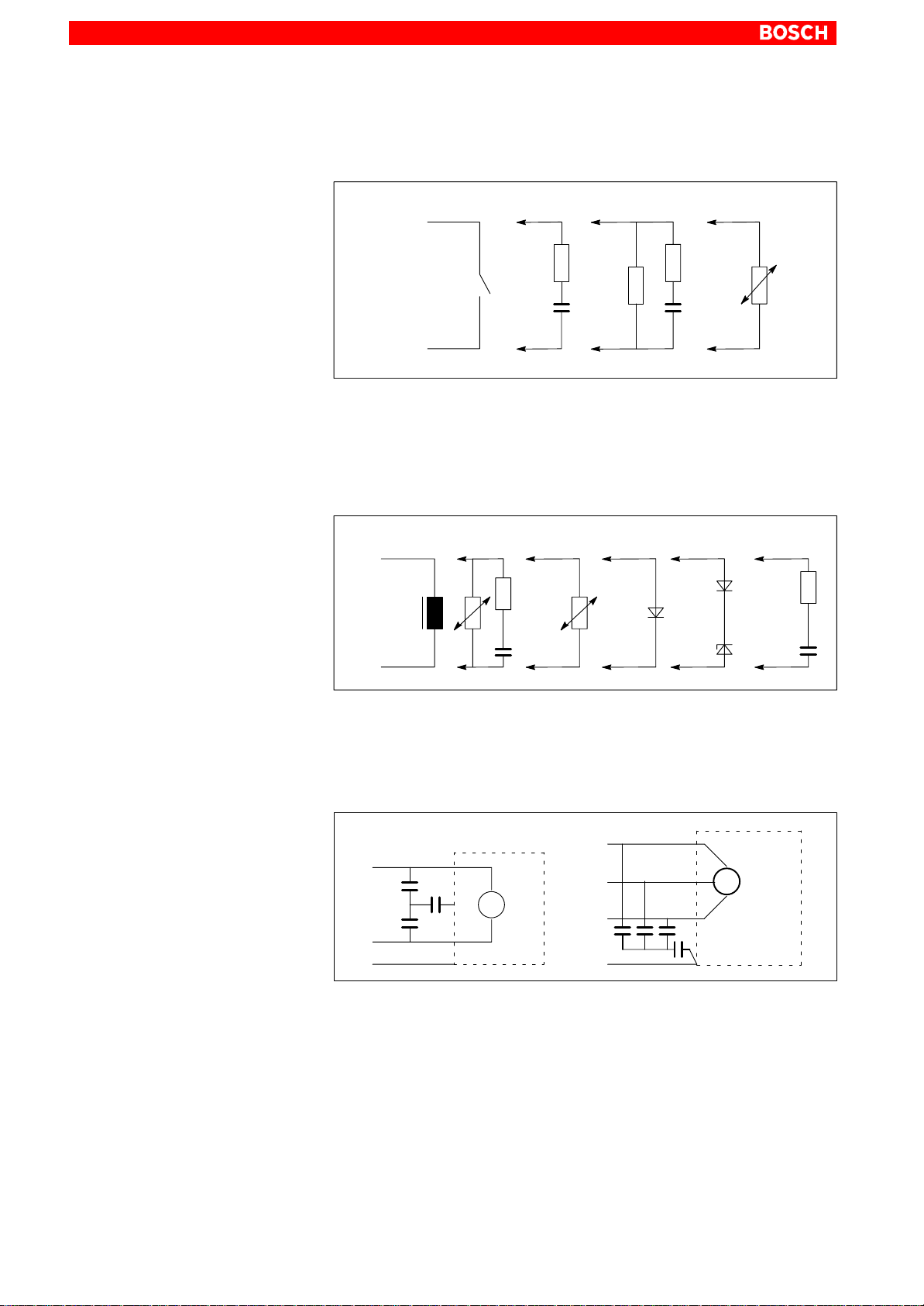
Interference suppression examples
Suppression of contacts
(Alternating current, direct current, offset DC current)
a) b) c)
R
C
R
Rp
C
VDR
to b) For sensitive contacts, residual current when contact open!
to c)
Voltage-dependent resistance, residual current when contact
open!
Suppression of an inductive load
(Motors, solenoid, relay and contactor coils)
−
a) b) c) d)
D
ZD
+
VDR
R
VDR
C
D
U
U
e)
R
C
to c)
to d)
For relay, drop-off delay.
For relay, defined drop-off delay
to e) Must be optimized for inductance!
Suppression example – mains input:
L
1
L
1
C
x
C
y
M
C
x
N
SL
~
L
2
L
3
C
x
SL
M
3
~
C
C
x
y
C
x
1070 073 825-103 (02.04) GB

5.3 Power supply
5.3.1 24 VDC-power supply
X25 24 VDC connection
Weidmüller push-lock terminal, MSTB 1.5, 4-pin
Max. conductor
cross!section:
X25
Electrical Connections
1.5 mm
4
1
2
(refer to next page)
AssignmentPin
40 V
3
2
0 V
24 V
24 V1
5–5
Rated voltage UN: 24 VDC ; +20%, –15% with a max.
of 1.5 Vss ripple voltage
Residual ripple at U
Interference and surge immu-
: refer to figure
N
= 35 V (for t < 100 ms)
U
max
nity:
Current draw at U
: max. 5 A
N
Input fuse: M6.3A (5x20) medium time-lag fuse
(position: refer to page 6–3)
Reverse voltage protection: via decoupling diode. Polarity reversal
will blow input fuse.
DANGEROUS ELECTRICAL VOLTAGE
The 24 VDC input voltage must fulfill the requirements of ”Safety Isolation”!
Offset AC components of the type produced by an unregulated 3-phase current bridge circuit without smoothing with a ripple factor of 5% (refer to DIN
40110/10.75, Section 1.2) are permissible.
As an upper voltage limit, this produces a maximum absolute value of 30.2 V
and, as a minimum voltage limit, a minimum absolute value of 18.5 V.
U
1,05.28.8 V = 30.2 V
1070 073 825-103 (02.04) GB
Upper limit 28.8 V
0,866.30.2 V = 26.1 V
1,05.20.4 V = 21.4 V
Lower limit
0,866.21.4 V = 18.5 V
20.4 V
30 el
cos (30 ) = 0.866
0
0
0
t

5–6
Electrical Connections
Cross–sections
depend on power
demand, but min. of 4
2
mm
. For higher power
demand, 2 x 4 mm
2
L1L2L3
PE
Power supply with
safety transformer
as per
EN 60742
400 VAC
24 VDC
Max. length 4 m
A
0 V Load24 V Load
PE
102 (green/yellow)
2
6
(blue)
(1)
A B
Earth bar
A = Terminal row 4
B = Terminal row 10
: Terminals in insulated design
102 (green/yellow)
2
2
(2)
PE
102 (green/yellow)
CPS21
Display with front
keyboard and PC
Power supply
(safety isolation, as per EN
60950)
X10_1
Supply and
distribution
circuit board
X25
X26 or X27
Cross–sections
depend on power
demand, but min. of
0.5
mm
2 (3)
(1) Connection absolutely necessary.
(Easily visible and removable).
(2) Preferred installation of PE terminal
bars: electrically conductive on the
mounting plate. PE terminal bars that are
installed in an insulated design must be
connected to the mounting plate by means
of copper straps of a length not exceeding
200 mm.
The cross–section of the copper straps
must equal at least that of the supply cable.
2
(3) 0.5 mm
0.75 mm
1.5 mm
, up to 4 meters
2
, up to 6 meters
2
, up to 10 meters
Distances in excess of 10 m require
separate power supply close to load!
1070 073 825-103 (02.04) GB

6 Interfaces and Connections
6.1 Overview
Overview of integrated connector types and their mating connectors.
Interfaces and Connections
6–1
Legend
on unit
A X24 START, STOP, EMERGENCY-STOP Weidmüller MSTB 1.5, 8–pin Female Weidmüller terminal,
A X25 Supply voltage 24 V Weidmüller MSTB 1.5, 4-pin Female Weidmüller terminal,
A X26 Supply voltage 24 V Weidmüller MSTB 1.5, 4-pin Female Weidmüller terminal,
A X27 Supply voltage 24 V Weidmüller MSTB 1.5, 2-pin Female Weidmüller terminal,
A X28 Distributor 24 Vout outputs Weidmüller MSTB 1.5, 8–pin Female Weidmüller terminal,
A X29 Distributor 24 Vout outputs Weidmüller MSTB 1.5, 8–pin Female Weidmüller terminal,
P Mouse PS/2 mini DIN mouse Female mini DIN PS/2, 6-pin Male mini DIN PS/2, 6–pin
P KBD PS/2 mini DIN keyboard Male mini DIN PS/2,
P USB USB USB socket, 4-pin USB plug, 4-pin
P 24 Vout Keyboard code output Female DB–15 Male DB–15
P Ethernet Network connection: Ethernet 10/100BaseTX Female RJ45, 8-pin Male RJ45, (8-conductor twisted pair)
P VGA VGA connection for external CRT monitor Female VGA HD connector,
P DP-Slave PROFIBUS DP
P X59 optional serial port: RS422/485 unused,
P COM1 Serial port:RS232 (UART 16550) free
P COM2 Serial port:
P COM3 Serial port:RS232 (UART 16550) kbd down-
P COM4 Serial port:
P LPT1 Parallel port:
P X10_1 PC power supply:
C X76 Floppy disk power supply +5VDC Female FDD mains connector,
C X75 Data connector for 3 1/2” floppy disk drive
C X19 Battery Male plug connector 2–pin Female connector. 2–pin, cable for in-
E X71 CAN on PCI-CAN expansion card Female DB-9 connector Male DB-9 connector
E X71 CAN on PCI_BM-CAN expansion card Female DB-9 connector Male DB 9-pin,
E X72 Busmaster on PCI_BM-CAN expansion card
Interface service Connector type
Keyboard code output (not used)
alternative to RS232; cf. COM1
alternative, optional RS485/422; cf. X59
RS232 (UART 16550) free
load or unused
RS232 (UART 16550) reserved for UPS logic
supports standard SPP, EPP, ECP mode
24 VDC
(SD, HD, ED)
(not used)
(integrated)
6–pin
15-pin.
Female DB-9 connector Male DB-9 bus connector, IP 20
no plug available because optional (male DB-9)
Male DB-9 connector Female DB-9 connector
Male DB-9 connector Female DB-9 connector
Male DB-9 connector Female DB-9 connector
Male DB-9 with plug cover –
Female DB-25 connector Male DB-25 connector (e.g., printer
Weidmüller push-lock terminal,
MSTB 1.5, 4-pin
4–pin
Male plug connector 34–pin
(IDC)
Male Weidmüller terminal,
MSTB 1.5, 10-pin
Mating connector or cable (from external device)
MSTB 1.5, 8-pin
MSTB 1.5, 4-pin
MSTB 1.5, 4-pin
MSTB 1.5, 2-pin
MSTB 1.5, 8-pin
MSTB 1.5, 8-pin
Keyboard cable with
male PS/2 mini DIN, 6-pin
Monitor cable with male VGA DB–HD,
15–pin
(Comnet DP bus system)
Female DB-9 connector
cable or parallel CD-ROM)
Female Weidmüller terminal,
MSTB 1.5, 4-pin
FDD mains cable with male 4–pin
connector
Female plug connector, 34-pin (IDC)
(data cable, floppy disk drive)
ternal battery
separate CAN bus for PLC signals
Female Weidmüller terminal,
MSTB 1.5, 10-pin
Connector
location:
1070 073 825-103 (02.04) GB
A = connection and distribution card P= PC housing side
C= on carrier board (in PC housing) E = on expansion card

6–2
Interfaces and Connections
6.2 Position of Interfaces
Connection board and carrier board interfaces
Side view (side
of hinges)
+ –
X19
Rear view
Battery
connection
Rear
covering plate
PE conductor lug
Carrier
board
Floppy disk
data connector
X75
X76
Supply and distribution
circuit board
Floppy disk
power supply
Battery
Battery connection
Supply and
distribution
circuit board
X29
X28
X27
X25
X26
DP–ADR DIP
X24
SEL COM3 DIP
Floppy disk
power supply
(accessible through opening in housing)
Floppy disk
data connector
(accessible through opening in housing)
Batter
y
1070 073 825-103 (02.04) GB

PC and PCI Expansion Cards Interfaces, Fuse
Side view (from right)
Interfaces and Connections
6–3
PCI_BM-CAN Card
Busmaster
(X72)
CAN
(X71)
CAN for PCL
(X71)
PCI-CAN Card
PE conductor lug
24 VDC connector
24 V fuse (M6.3A)
unscrewable
1070 073 825-103 (02.04) GB

6–4
Interfaces and Connections
6.3 Connection and Distribution Card
The connection and distribution card is obtainable in two models depending
on the configuration that was ordered.
D Standard distribution card with common EMERGENCY OFF and STOP
circuit
D Special distribution card with separate EMERGENCY OFF and STOP
circuits.
The connection and distribution card is to be wired in any case. The components to be connected are as follows:
D 24 VDC supply voltage of CPS21
D all buttons on the front panel
(START, STOP, EMERGENCY OFF)
D key codes of the front panel
Common EMERGENCY
OFF and STOP circuit
(Standard distribution card)
X24
X25
X26
X27
Pin
X24
8
1
4
1
4
1
2
1
X25
X26
Assignment
8
24 V (Lamp in START button)
7
6
5
4
3
2
1
4
3
2
1
4
3
2
1
Connector START key
Connection EMERGENCY OFF and OFF
button
for connection in series (1st path)
Connection EMERGENCY OFF / OFF recognition
Connection EMERGENCY OFF and OFF
button
for connection in series (2nd path)
0V
0V
24V
24V
0V
0V
24V
24V
Connection
supply voltage
Internal connection to
X10_1
X27
2
0V
1
24V
Internal connection to
fan power
1070 073 825-103 (02.04) GB

Interfaces and Connections
6–5
DANGEROUS ELECTRICAL VOLTAGE
Improperly or incorrectly installed EMERGENCY OFF circuit may
lead to life endangering situations and substantial material damages!
Please integrate the EMERGENCY OFF button of the CPS21 into the
EMERGENCY OFF circuit as well!
Supply and distribution circuit board
8
X28
1
8
X29
1
Pin Assignment
X28
8
7
6
5
4
3
2
1
X29
8
7
6
5
4
3
2
1
24VOut Bit4
24VOut Bit3
24VOut Bit2
24VOut Bit1
24VOut Bit4
24VOut Bit3
24VOut Bit2
24VOut Bit1
Internal
connection
of 24 Vout
Distributor
KeysCodes
1070 073 825-103 (02.04) GB

6–6
Interfaces and Connections
Overview of connections ex works:
Connector 24Vout
with cable
Connector X10_1
(24 VDC) with cable
X27
X24
X25
X26
X28
X29
X27 fanpower
supply
X26 to X10_1 (24
VDC) connector
X28 to connector
24 V out
Cable (10 mm2) to PE
lug, front panel and
housing
1070 073 825-103 (02.04) GB

Interfaces and Connections
6–7
Separate EMERGENCY OFF and STOP
circuits
(Special distribution card)
4
X27
1
4
X26
1
4
X25
1
3
X24
1
8
X28
1
8
X27
X26
X25
X24
X28
AssignmentPin
4
0V
3
0V
2
24V
1
24V
4
0V
0V
3
24V
2
24V
1
4
0V
3
0V
24V
2
24V
1
3
24 V (Lamp in START button)
2
1
8
7
6
5
4
3
2
1
Connector START key
24VOut Bit8
24VOut Bit7
24VOut Bit6
24VOut Bit5
24VOut Bit4
24VOut Bit3
24VOut Bit2
24VOut Bit1
Internal connection to
fan power
Internal connection to
X10_1
Connection
supply voltage
Internal
connection
of 24 Vout
X29
X31
X32
X29
24VOut Bit8
8
24VOut Bit7
7
24VOut Bit6
6
1
4
1
X31
4
1
X32
5
4
3
2
1
4
3
2
1
4
3
2
1
24VOut Bit5
24VOut Bit4
24VOut Bit3
24VOut Bit2
24VOut Bit1
Connector STOP key
for connection in series (2nd path)
Connector STOP key
for connection in series (1st path)
Connection EMERGENCY OFF
for connection in series (2nd path)
Connection EMERGENCY OFF
for connection in series (1st path)
Distributor
KeysCodes
1070 073 825-103 (02.04) GB

6–8
Interfaces and Connections
6.4 Connection of the optional Coolkit to the connection and distribution card
If the CPS21 is equipped with the optional extra Coolkit (for installation see
section 4.4), then the electrical connections for the Coolkit must be made via
the connection and distribution card.
Standard connection and distribution card
The 24 VDC Coolkit connecting cables (red = + / black = 0 V) are connected
as follows to the standard CPS21 connection and distribution card:
L Replace the existing 4 conductor cable between the X26 plug and the X10_1
connecting plug by a 2 conductor cable 2 x 0.75
2
. The cable is connected on
the one side to the X26 / Pin 2 (+ 24 V) and X26 / Pin3 (0 V), and on the PC
side to the X10_1 / Pin 2 (+ 24 V) and X10_1 / Pin 3 (0 V). Alternatively it is
also possible to clamp off the two wires that are not needed on the existing 4
conductor cable.
L Connect the Coolkit’s red connection cable to the X26 / Pin 1 and the black
cable to the X26 / Pin 4.
X10_1
4
1
red
black
to the Coolkit
Special distribution card
X26
4
X26
to the Coolkit
1
The 24 VDC connecting cables (red = + / black = 0 V) are connected to the
free pins of the X27 plug on the CPS21 special distribution card (see page
6-6) (Pin 1,2 = + 24 V; Pin 3,4 = 0V).
1070 073 825-103 (02.04) GB

6.5 Floppy Disk Connection
X75 Drive ”A” connector
Used to connect an optional floppy disk drive. The integrated floppy disk
adapter supports the following types of floppy disk drives:
D 3,5 ”
D Double density (720 kB)
D High density (1.44 MB)
D Enhanced floppy mode (2.88 MB)
. Only one type of drive can be connected at a time.
Male connector, 34–pin (on carrier
board)
Type: 3.5” HD (standard)
Cable length: Max. 0.5 m
Cable type: 34–conductor ribbon cable, screened
Interrupt (IRQ): empty
I/O address: 300H
BIOS preset: Floppy disk controller: Enabled
Interfaces and Connections
in the ”I/O Device Configuration” submenu
6–9
X75
Pin Assignment
GND
1
3
11
13
15
17
19
21
23
25
27
29
31
33
GND
GND
5
GND
7
9
GND
GND
GND
GND
GND
GND
GND
GND
GND
GND
GND
GND
GND
X75
1
34
Screened ribbon cable
1
PinAssignment
24Density Select
N/C
N/C
6
Index
8
10
Motor Enable A
Drive Sel B
12
Drive Sel A
14
Motor Enable B
16
Direction
18
Step
20
Write Data
22
Floppy Write Enable
24
26
Track 0
Write Protect
28
30
Read Data
Head Select
32
Disk Change
34
No. 1 conductor
Floppy ”A”
boot drive
connector
1070 073 825-103 (02.04) GB
40

6–10
Interfaces and Connections
X76 Floppy disk drive power supply
Power supply for optional floppy disk drive.
Female coupler, 4-pin
Supply voltages: +5 V, +12 V, 0.9 A
max.
Installation
X76, socket
21334
Pin Assignment
1 +12 V
2
4 +5 V
GND
GND
. The +5 V and +12 V operating voltages are monitored for overvoltage
and undervoltage conditions. The detection of a faulty voltage causes
the PC power supply to switch off immediately. –12 V potential is not
monitored.
L Connect the ”Floppy A boot drive” connection end of the ribbon cable to the
floppy disk drive. Connect the other end of the cable to the X75 floppy disk
connector. O n the ribbon cable, observe the red marking of the no. 1 conductor which must always be connected to PIN 1 of the connected devices.
In most cases, notched connectors will provide for connections with proper
conductor alignment.
L The power supply for the floppy disk drive must also be connected. This is
accomplished by connecting the connecting cable on the floppy disk drive
(4–pin plug connector) to the X76 power supply connector.
L If the system does not recognize the floppy disk drive, the latter must be acti-
vated in the ”I/O Device Configuration” BIOS submenu by changing from
”Disabled” to ”AUTO” or ”Enabled”. If necessary, the floppy disk type must
also be selected under ”
Diskette 1
” in the main menu.
In order to start the BIOS setup function, press <F2> when the ”Press <F2>
to enter Setup” display appears during booting. Then the BIOS main menu
will be displayed. Make the above mentioned settings. Leave BIOS via the
”Exit Saving Changes” entry in the Exit menu.
T o do so, press the <Z> key if you have a keyboard with a German layout (Z =
for Yes).
Y
L If the floppy disk drive is not accessible, check the connections for
D proper seating of all cables and connectors.
D normally working supply voltage.
1070 073 825-103 (02.04) GB

6.6 COM1 through COM4 Serial Ports, USB
6.6.1 Pin assignment
CAUTION
Functional failures caused by poor screening!
Use only metallic or conductive connector/coupling shells providing
large-area screen contact.
COM1 Serial port, freely assignable
Male DB-9 connector
Type: RS232
Cable length: Max. 15 m
Cable type: Screened, min. cross-section 0.14 mm
Transmission rate: Max. 115200 bps
Handshake: Hardware- and software handshake (X
Interrupt (IRQ): 4
I/O address: 3F8H or AUTO (recommended)
BIOS preset: Serial Port A: Enabled
Interfaces and Connections
2
ON
, X
OFF
6–11
)
COM1
1
DCD
2
RX
1
69
5
TX
DTR
GND
DSR
RTS
CTS
RI
Screen applied to metal shell of
DB-9 plug connector
3
4
5
6
7
8
9
to peripheraldevices
Assigned as RS-232 (COM1):
DCD Data Carrier Detect. RCV channel used, for example, by a con-
nected modem to inform the PC that it is receiving a carrier
signal (active connection).
RX Receive Data. Line on which data is received.
TX Transmit Data. Line on which data is transmitted to peripheral.
DTR Data Terminal Ready. XMIT channel used by the PC to signal
to a connected peripheral device that its interface is switched
on and initialized.
DSR Data Set Ready. RCV channel used by the connected periphe-
ral device to inform the PC that it is switched on and inilitalized.
GND Signal Ground
RTS Request to Send. RCV channel used by the connected peri-
pheral device to signal to the PC that is wishes to transmit
data.
1070 073 825-103 (02.04) GB

6–12
Interfaces and Connections
COM2 Serial port, freely assignable
CTS Clear to Send. XMIT channel used by the PC to signal to the
connected peripheral device that it is permitted to transmit
data.
RI Ring Indicator. Receive line on which a connected modem in-
forms the PC of the presence of an active call.
Screen Contact with housing frame via metallic shell of the D-Sub
connector.
Male DB-9 connector
Type: RS232
Cable length: Max. 15 m
Cable type: Screened, min. cross-section 0.14 mm
2
Transmission rate: Max. 115200 bps
Handshake: Hardware- and software handshake (X
ON
, X
OFF
)
Interrupt (IRQ): 3
I/O address: 2F8H or AUTO (recommended)
BIOS preset: Serial Port B: Enabled
COM2
1
DCD
2
RX
3
TX
4
1
69
5
DTR
GND
DSR
RTS
CTS
RI
5
6
7
8
9
Screen applied to metal shell of
DB-9 plug connector
Refer to page 6–11 for explanations on pin assignments.
To peripheraldevices
1070 073 825-103 (02.04) GB
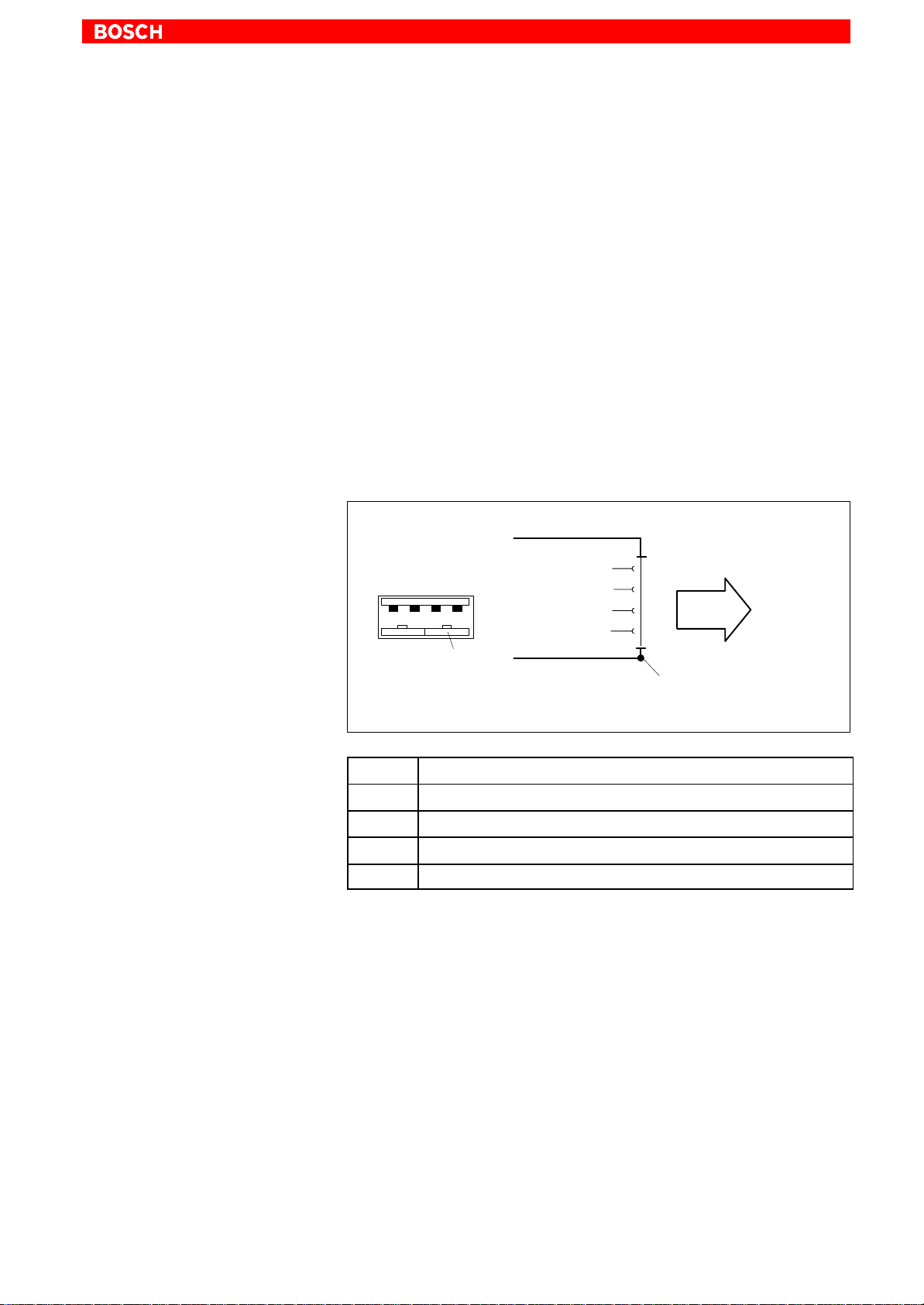
Interfaces and Connections
COM3 Serial Port, assigned
D Input for key codes and LED control on front panel
D If required, used for software download of new key codes
(refer to section 7.5.4)
COM4 Serial Port, assigned
The COM4 port is internally occupied by the uninterruptible power supply
(UPS), and thus, only available for external applications if an uninterruptible
power supply is not required. The interface plug is covered by a hood.
USB Serial interface (Universal Serial Bus), currently not supported
The USB interface provides for the connection of up to 128 devices equipped
with USB functions.
USB socket, 4-pin
6–13
USB
USB
2143
USB_P
USB1
USB2
USB_M
Screen
1
2
3
4
PIN Function
1 USB power supply (max. 500 mA)
2 File
3 File
4 USB Ground
USB
device
Screen applied to metal shell of
DIN plug connector
1070 073 825-103 (02.04) GB

6–14
Interfaces and Connections
6.6.2 Settings
Control Panel
PhoenixBIOS
For information about setting the communication parameters for serial interfaces, refer to the manual supplied with the installed operating system.
Windows NT: Go to Start / Settings / Control Panel, etc.
The default BIOS presets for COM1 (serial port A) and COM2 (serial port B)
are AUTO (automatic parameter assignment). If you desire direct parameter
assignment, you should adopt the following settings:
D COM1 = 3F8H
D COM2 = 2F8H
Ex works, the settings for COM3 and COM4 are preset to not available
(Disabled).
. The modification of BIOS settings is discussed in the manual entitled
”BT150, BT200, BT215 and CPS21_3, Software Configuration”. Modifications are necessary only in the event that changing the default settings for COM1 through COM2 and USB serial ports is required.
CAUTION
With regard to IRQ and I/O address, the connected devices must correspond to the BIOS settings made for the respective serial port.
1070 073 825-103 (02.04) GB

6.7 LPT1 parallel port
LPT1 Parallel port for printer, scanner, CD-ROM, etc.
Interfaces and Connections
Male DB-25 connector
Type: SPP (ex works), EPP, ECP
Cable length: Max. 3 m
Cable type: Screened, min. cross-section 0.14 mm
Interrupt (IRQ): 7
I/O address: AUTO or 378H (recommended)
LPT1
6–15
2
LPT1
1
14 25
Interface mode
EPP
SPP
Write
STROBE
Data0
Data0
Data1
Data1
Data2
Data2
Data3
Data3
Data4
Data4
Data5
Data5
Data6
Data6
Data7
Data7
Intr
ACK
Wait
13
n.u.
n.u.
Datastb
n.u.
n.u.
Addrstrb
GND
GND
GND
GND
GND
GND
GND
GND
BUSY
PAPER out
SEL out
AUTOFD
ERROR
INIT
SEL in
GND
GND
GND
GND
GND
GND
GND
GND
1
2
3
4
5
6
7
8
9
10
11
12
13
14
15
16
17
18
19
20
21
22
23
24
25
Max. 3m
To peripheral
device
Screen applied to metal
shell of DB-9 plug
connector
1070 073 825-103 (02.04) GB
The parallel port normally runs in the default SPP mode. Provided that suitable peripheral devices are present, it can also be operated in EPP (Enhanced Parallel Port) or ECP (Extended Capabilities Port) mode. BIOS settings
must be changed accordingly (refer to ”BT150, BT200, BT250 and
CPS21_3, Software Configuration” manual).
CAUTION
Functional failures caused by poor screening!
Use only metallic or conductive connector/coupling shells providing
large-area screen contact.

6–16
Interfaces and Connections
6.7.1 Parallel Port for CD-ROM
To install a CD-ROM drive with a parallel interface connection, please follow
the instructions of the manufacturer. New settings in the operating system
and/or BIOS may be necessary.
The following CD-ROM drive with parallel interface connection may be used:
Type: CD-Jet SL (Multiport CD-ROM drive parallel port)
Manufacturer: Multiport Computer-Systeme GmbH, Ruselstr. 84, D-94469
Deggendorf
1070 073 825-103 (02.04) GB

6.8 Ethernet Connector
Ethernet network connection
Interfaces and Connections
6–17
The CPS21 can be connected to an Ethernet network via the Ethernet connector. To facilitate data communications, the required network protocols
(e.g., TCP/IP) must be recognized by the operating system and the network
application programs running on the PC.
Female RJ45, 8-pin
Type: Ethernet 10/100BaseTX
Cable length: Max. 100 m
Cable type: Screened, twisted pair
Transmission rate: 10 or100 Mbit/s
Interrupt (IRQ): 5
I/O address: 340H
Ethernet RJ45
8
1
Ethernet
max. 100 m
TXD+
TXD−
RXD+
RXD−
1
2
3
4
5
6
7
8
To network
The driver configuration of the network connection can be called up in the
task bar or in ”Control Panel”, with the icon ”Network Interface card”. Here it
is possible to set the data transfer rate over the network to 10 Mbit/s or
100 Mbit/s.
. Note that the network card of the remote communication partner must
be able to handle the same data transfer rate.
1070 073 825-103 (02.04) GB

6–18
Interfaces and Connections
6.9 VGA Video Port
VGA External monitor port
The VGA port accepts an external monitor (CRT) for operation via the built-in
video adapter. The external monitor may be operated concurrent with the integrated flat panel display.
Female VGA HD, 15-pin
Cable length: Max. 1.5 m
Cable type: Screened, min. cross-section 0.14 mm
Max. resolution: 1280 x 1024 pixels, max. 16 million colours
2
VGA
max. 1.5 m
RED
GREEN
BLUE
ID2
VGA
1
15
GND
RED GND
GREEN GND
BLUE GND
−
Digital GND
ID0
ID1
Hsync
Vsync
ID3
1
2
3
4
5
6
7
8
9
10
11
12
13
14
15
Display
Screen applied to metal shell of
DB-9 plug connector
Video-Adapter CRT
Resolution and colours for the VGA port can be selected in the Control Panel
of the operating system.
The following standard resolutions can be used with a minimum refresh rate
of 72 Hz:
D VGA mode: 640 x 480 pixels, 72 Hz, 256 colors
D SVGA mode: 800 x 600 pixels, 72 Hz, 256 colors
D XGA mode: 1024 x 768 pixels, 72 Hz, 256 colors
D SXGA-Mode: 1280 x 1024 pixels, 72 Hz, 256 colors
Up to 16 million colors can be displayed.
. The external monitor must be connected before the PC is booted in or-
der for the VGA interface to be initialized.
1070 073 825-103 (02.04) GB

Interfaces and Connections
CAUTION
Setting incorrect resolutions and colors can destroy your monitor!
Observe the specifications applying to your CRT or LCD monitor,
and adapt the operating system parameters accordingly.
Recommended monitors for external use are low-radiation models to
TCO95. In addition, you should achieve the desired display resolution at a
refresh rate of no less than 72 Hz.
6–19
. The insertion of a graphics card disables the integrated video adapter.
1070 073 825-103 (02.04) GB

6–20
Interfaces and Connections
6.10 Keyboard Ports
KBD PS/2 mini DIN keyboard port
An additional external keyboard can be connected to this port.
Female PS/2 mini DIN, 6-pin
Cable length: Max. 1.5 m
Cable type: Screened, min. cross-section 0.14 mm
BIOS preset: System Keyboard: Present
KBD
KBD
6
5
3
4
21
Screen
Keyboard Data
GND
Power, +5VDC
Keyboard Clock
1
2
3
4
5
6
max. 1.5 m
Keyboard
Screen applied to metal shell of
DIN plug connector
2
Keyboard adapter
Mini DIN keyboard
port on PC
In the event that the system fails to recognize the keyboard, it must be activated by changing the BIOS setting from ”Absent” to ”Present”.
In the event that the MF2 keyboard is equipped with a standard 5-pin DIN
plug, you will require a keyboard plug adapter to a female PS/2 Mini DIN connector.
A suitable adapter is approx. 20 cm in length with a DIN connector and a mini
DIN coupling on the ends.
Connector assignment as per diagram below.
These premanufactured adapters are available from computer stores.
6
Screen
DIN connector (male)
1
2
3
4
5
6
4
21
PS/2 mini
2
5
3
4
1
5
3
Screen
Standard
DIN connector (female)
MF2
Keyboard Data
GND
Power, +5VDC
Keyboard Clock
2
3
4
5
1
keyboard port
Screen applied to metal shell of
DIN plug connector
max. 0.2 m
1070 073 825-103 (02.04) GB

6.11 Mouse Port
Mouse PS/2 mouse port
An external mouse can be connected to this port if the integrated key mouse
(see section 7.2.5) shall not be used.
Female PS/2 mini DIN, 6-pin
Cable length: Max. 1.5 m
Cable type: Screened, min. cross-section 0.14 mm
Interrupt (IRQ): 12
BIOS preset: PS/2 Mouse: Auto Detect
Mouse
5
6
3
4
21
Screen
Interfaces and Connections
Mouse
Mouse Data
GND
Pwer, +5VDC
Mouse Clock
1
2
3
4
5
6
Mouse
6–21
2
max. 1.5 m
Screen applied to metal shell of
DB!9 plug connector
In the event that the system fails to recognize the PS/2 mouse, it must be
activated by changing the BIOS setting from ”Absent” to ”Present”.
A subsequent connection of the external mouse will not be recognized by the
operating system because initialization is only possible during ”booting”.
. The connected mouse must be PS/2-compatible.
The BIOS normally reserves IRQ12 for the PS/2 mouse. If there are address conflicts, e.g. if IRQ 12 has already been occupied by another PC
expansion card, you should change the IRQ of the expansion card to
one that is still free.
1070 073 825-103 (02.04) GB

6–22
Interfaces and Connections
6.12 DP-Slave Port
DP-Slave PROFIBUS DP connector
6.13 24 Vout port
24 V out output key codes
The key codes of the front panel keys are transferred from the PC to this
PROFIBUS slave connector.
This interface is not used.
The codes of certain keys on the front panel keyboard are transferred to outputs of the 24 Vout port. From here, the key codes are transferred over the
already existing wiring to the X28 plug on the connection and distribution
card (refer to section 6.3). At this point they can be read for further processing via an external input node.
Female DB-15
Cable length: Max. 20 m
Cable type: Screened, min. cross-section 0.14 mm
24VOut
Data 0
Data 1
Data 2
Data 3
Data 4
24 V Out
1
915
8
Data 5
Data 6
Data 7
24V-GND
Screen applied to metal shell of
DB-9 plug connector
1
2
3
4
5
6
7
8
9
10
11
12
13
14
15
2
max. 20 m
1070 073 825-103 (02.04) GB

6.14 Expansion Card Interfaces
6.14.1 PCI_BM-xxx Card
This busmaster expansion card is the interface of the software PLC.
The PLC signals are transmitted over the integrated system bus.
Depending on model, X71 has been assigned one of the following bus sy-
stems:
Name Bus system
PCI_BM–CAN CAN bus
PCI_BM–IBS InterBus-S
PCI_BM–DP PROFIBUS-DP
Interfaces and Connections
6–23
X71 CAN-Bus ”PCI_BM-CAN”
Male DB-9 connector
Type: CANopen bus
Cable length: depending on baud rate
Cable type: Screened, min. cross-section 0.14 mm
Transmission rate: up to 1 Mbit/s
X71
6
9
1
5
max. 25 m with 1 Mbit/s
X71 CAN
reserved
CAN_L
GROUND_ISO
reserved
CAN−SHIELD
CAN_GND
CAN_H
reserved
CAN_24V
Screen applied to metal shell of
DB-9 plug connector
1
2
3
4
5
6
7
8
9
2
CAN bus
1070 073 825-103 (02.04) GB
X72 This interface is not used.

6–24
Interfaces and Connections
X71 Interbus S ”PCI_BM-IBS”
Female DB-9
Type:InterBus-S Remote (as per EN 50178)
X71 InterBus-S
X71
6
9
1
5
DO
DI
GND!ISO
GND
+5V ISO
DO
DI
5V
−
1
2
3
4
5
6
7
8
9
InterBus-S
Screen applied to metal shell of
DB-9 plug connector
. Please comply with the installation instructions and recommenda-
tions of Phoenix-Contact, e.g. IBS SIG Part 1 UM or the IBS SYS INST
UM installation manual.
X72 This interface is not used.
1070 073 825-103 (02.04) GB

X71 PROFIBUS DP ”PCI_BM-DP”
Female DB-9
Max. cable length depending
on baud rate
(as per DIN EN 19245 Part 3):
12000 kbit/s 100 m
Cable type: Screened, min. cross-section 0.14 mm
X71 PROFIBUS-DP
Interfaces and Connections
500 kbit/s 400 m
1500 kbit/s 200 m
3000 kbit/s 100 m
6000 kbit/s 100 m
6–25
2
X71
6
9
1
5
Meaning
−
−
Receiving/Transmitting S data P
Repeater control signal P
Data ground
Voltage supply+
−
Receiving/TransmittingS data N
Repeater control signal N
−
−
File
Repeater+
GND ISO
+5V ISO
−
Data−
Repeater−
1
2
3
4
5
6
7
8
9
External PROFIBUS DP node
RS!485 signal +
TTL signal for repeater control
ISO!GND
Voltage supply for
repeater (+5 V; 100 mA)
RS!485 signal −
GND for repeater P
Screen applied to metal shell of
DB!9 plug connector
X72 This interface is not used.
1070 073 825-103 (02.04) GB

6–26
Interfaces and Connections
6.14.2 PCI_CAN Card
This interface is a second CAN bus for fast transmission of measured data to
the PC.
X71 CAN bus
Male DB-9 connector
Type: CAN-Bus
Cable length: depending on baud rate
Cable type: Screened, min. cross-section 0.14 mm
Transmission rate: up to 1 Mbit/s
max. 25 m with 1 Mbit/s
2
X71 CAN
X71
6
9
1
5
reserved
CAN_L
GROUND_ISO
reserved
CAN−SHIELD
CAN_GND
CAN_H
reserved
CAN_24V
1
2
3
4
5
6
7
8
9
CAN bus
Screen applied to metal shell of
plug connector
1070 073 825-103 (02.04) GB

7 Display and Control Elements
The CPS21_3 / CPS21_4 is provided with the following display and control
components:
D Display
D Membrane keyboard
D Buttons for START, STOP, and EMERGENCY OFF
D LED displays
D Insertion labels for front panel
D Keyboard controller
Display and Control Elements
7–1
CPS21_3
Front
13.8” Color TFT Display
Navigation keys
LEDs
Rear
Battery
(intern
al)
Handle
1070 073 825-103 (02.04) GB
Front panel
Keyboard
Handle
PC
(internal)
Plastic
frame

7–2
Display and Control Elements
CPS21_4
Tilt/tip adapter
Battery
(internal)
LEDs
15” Color TFT Display
Navigation keys
Handle
Front panel
Keyboard
Handle
Aluminum housing
PC
(internal)
Plastic
frame
1070 073 825-103 (02.04) GB

7.1 Display
Video Adapter LCD
Display and Control Elements
The CPS21_3 is equipped with a 13.8” flat color LCD display; the CPS21_4
has a 15” display. The screen is non-reflecting and scratch resistant.
Brightness and contrast are preset at the factory. Colors can be adapted to
the user’s requirements via the operating system or by means of the application software.
For maintenance work on the display, the PC can be hinged down if the housing is open. For instructions, please refer to section 8.2.2.
The integrated video adapter supports VGA-CRT displays (refer to section
6.9) and flat-screen LCDs. Both displays can be operated in parallel.
D Video RAM: 2 MB
7–3
. The insertion of a graphics card disables the integrated video adapter.
. The 1024 x 768 pixel resolution is preset with every booting up of the
7.1.1 Backlight Function
For optimal readability the flat display is preset to:
D 1024 x 768 pix-
els:
CPS21. This applies to the ”LCD Video Adapter” and the ”CRT Video
Adapter”.
The backlight provides the background illumination for the LCD display. As
its service life is limited, only 50% of its original brightness will remain after
approx. 15,000 operating hours.
Refer to section 8.2.2 for information about replacing the backlight unit.
To extend the service life of both display and backlight tube, the flat screen
display features a timer (”sleep”) function for the backlight .
This function “darkens” the display when no keyboard or mouse action has
occurred on the CPS21 for a defined period of time. The length of the defined
interval can be selected in the PC BIOS and in the Windows Control Panel.
with 64k colors
Enabling the ”Backlight Off” function
1070 073 825-103 (02.04) GB
Pressing a key or moving the mouse again activates the backlight, making
the display visible once more.
D In the BIOS setup program, go to the ”Power Management Setup” menu
option. Select the ”OnBoard LCD Backlight Timer OFF” submenu, and
select a time interval between 28 seconds and 14 minutes.
D Install a screen saver such as ”Blank Screen” that will switch the display
to a ”black signal” in the operating system. Select the ”Wait” period after
which the screen saver will be activated. The interval selected here is added to the ”Backlight Timer OFF” interval that was selected in the BIOS.

7–4
Display and Control Elements
7.2 Keyboard
The front panel is provided with a medium resistant membrane keyboard (IP
65). It contains 57 keys (or buttons), 15 of which are provided with an LED.
Some keys can be assigned multiple functions.
In addition, 3 buttons are integrated in the front panel:
D START, illuminated
D STOP
D EMERGENCY OFF
7.2.1 Block of Function Keys
The following key blocks belong to those keys whose function can be programmed by means of the application program:
D 8 keys arranged horizontally below the display
(e.g., for the softkey functions customary in industry)
Description of this key row: F1...F8
D 4 keys F9...F12, arranged horizontally below the F1...F8 function key
block
Description of this key row: provided by the user
(description tags)
D 2 x 3 navigation buttons vertically arranged on the right and left side of the
display inside the handlebar.
Designation: none
Handlebar
Navigation keys
Function keys
F1..F8
Function keys
F9..F12
Navigation keys
1070 073 825-103 (02.04) GB

7.2.2 Key Blocks ”Control”
The programmable key blocks ”Control 1...3” contain 16 keys, 14 of which
are provided with an integrated LED.
Display and Control Elements
7–5
7.2.3 Key Block ”Machine”
The key block ”Machine” contains the following keys:
D START button (white, illuminated)
D STOP button (black)
D EMERGENCY OFF (red, complying with the requirements of EN 418)
Keypad
”Control 1”
Keypad
”Control 2”
START
STOP
EMERGENCY OFF
Keypad
”Control 3”
1070 073 825-103 (02.04) GB

7–6
Display and Control Elements
7.2.4 Number, Cursor Control and Special Keys Blocks
Keys may feature fixed (permanent) assignments or allow programming via
the application program.
CPS21_3
Special keys Key mouse
Cursor control block
Number
block
For easy operation, the keys are divided into blocks.
D Number block (15 keys)
D Numbers 0 to 9, –, . ,
Esc (Escape)
(Tabulator)
(Return)
D Cursor block and key mouse (7 keys)
D Cursor keys: right, left, up, down
D Key mouse: activate/deactivate mouse, mouse key right and left
D Special keys (7 keys)
D Page up (to beginning of page)
Page dn (to end of page)
Shift (capital/small letters)
Alt (Alternate)
(Backspace)
Del (Delete)
Info (call up information)
1070 073 825-103 (02.04) GB

7.2.5 Key Mouse
Display and Control Elements
7–7
The key mouse is a substitute for an external mouse.
The key mouse is activated (LED on) and deactivated (LED off) with the
”mouse” key (key with mouse symbol and LED).
The 4 cursor keys are used to move the mouse cursor upwards, downwards,
to the left and to the right, and diagonally in all 4 directions.
The keys ”
” and ” ” correspond to the right and left mouse button.
left mouse
Mouse
movement
LEFT
button
Mouse
movement
Diagonally to
upper left
Mouse
movement
Diagonally to
bottom left
Key mouse
activate/
deactivate
Mouse
movement
DOWN
Mouse
movement
UP
right mouse
button
Mouse movement
Diagonally to
upper right
Mouse
movement
RIGHT
Mouse movement
Diagonally to
bottom right
. If the key mouse is active, the cursor keys are not available.
If an external mouse is connected before start up or after RESET, it is recognized automatically and the key mouse is deactivated. Activating the key
mouse is then not possible, even if the external mouse is unplugged. To activate the key mouse, the CPS21 must be rebooted.
1070 073 825-103 (02.04) GB
. Subsequent connection of an external mouse will not be recognized by
the operating system because initialization is only done during ”boo-
ting”.

7–8
Display and Control Elements
7.3 LED Indicators
7.3.1 Hardware Indicators
The PC system is provided with 5 LEDs for indications on hardware. In the
case of the CPS21_4 the LEDs are not labeled. The assignments are the
same as for the CPS21_3 (see illustration).
5 LED indicators
Please take appropiate measures if one of the following LEDs indicates an
error or a message:
LED Display Meaning Measures
V
VOut LED green Standard operation –
HD LED yellow Access to hard disk –
Temp LED off Standard operation –
UPS LED off Standard operation –
LED green Standard operation –
in
LED off No supply voltage 24 VDC Check the supply vol-
tage at the power supply unit!
LED off Internal voltage +5V / +12V not
available
LED flashes
red
Internal housing temperature
exceeds > 50 °C. Shutdown
will occur if temperature continues to rise.
Check the supply voltage at the power supply unit!
Lower ambient temperature!
Check fan of PC!
LED red CPS21 currently running on
battery power, i.e. no mains
power available!
LED flashes
red
Discharged or defective rechargeable battery, or battery
not connected.
Restore mains power,
initiate a controlled
CPS21 restart!
Check battery!
Observe 5 hour recharging time!
1070 073 825-103 (02.04) GB

In addition, the PC is provided with an LED-equipped RESET button (accessible when housing is open) located on the same side as the interfaces:
Button: Initiates rebooting process of PC.
LED (red): RESET button is pressed
7.3.2 Customer-Specific Indicators
8 LEDs at the upper rim of the CPS21_3 and CPS21_4 are provided for customer–specific indications.
CPS21_3
Space for LED description
Display and Control Elements
7–9
7 LED indicators
(yellow)
Space for LED description
7 LED indicators
(yellow)
1 LED indicator
(red)
CPS21_4
1 LED indicator
(red)
1070 073 825-103 (02.04) GB
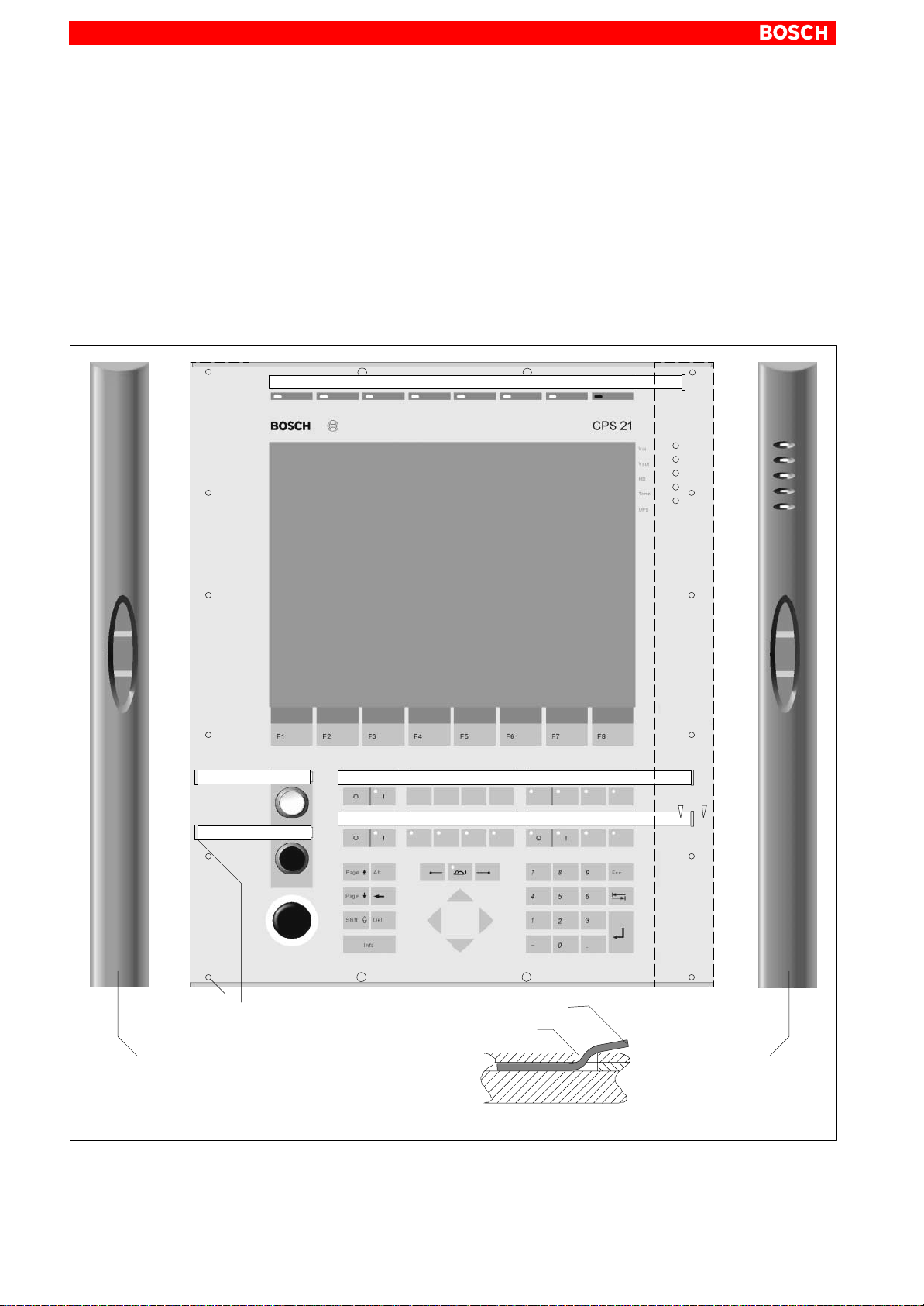
7–10
Display and Control Elements
7.4 Front Panel Labeling
Providing for customer-specific terminal legends, individual insertion labels
can be pushed in at the edges of the CPS21:
D customer-specific LED indicators (upper edge of front panel)
D programmable key blocks “Control 1..3”
D integrated buttons
The openings for inserting the label (cross-section: 2.5 x 12.0 mm) are located below the handlebars, and are therefore sealed from the outside.
Handlebar
(dismounted)
Opening for insertion label in
the membrane
cross–section: 2.5 x 12.0 mm
6 vertical bores each for
fastening handlebars with
screws.
AA
Insertion label
Opening for
inserting the label
Handlebar
(dismounted)
View A – A
1070 073 825-103 (02.04) GB

Display and Control Elements
7–11
Instructions:
1. The CPS21 must be turned off and completely de-energized.
2. T ake the handlebars off the front panel. To do so, unscrew the 12 screws
(6 for each handlebar) that are positioned vertically on the rear edge of
the plastic frame.
3. Now, insert the labels in the openings especially designed for this.
4. Reassemble the components in the reverse sequence to that described
above.
Restart the system. Make sure that the labels can be read easily.
CAUTION
Incorrect labeling may lead to false operation!
Make sure that the descriptions on the labels correspond to the functions of the described keys and LEDs.
Dimensions of the labels
Readable section
Insertion
direction
8
Insertion
direction
2 labels
for buttons
The label is made of plastic or laminated paper. It can also be written on in a
normal printer. The height of the readable section is max. 8 mm.
Space for descriptions
on the insertion label
approx.
331
2 labels
for control keys
approx.
283
Insertion
direction
1 label
for 8 LEDs
12
approx.
94
1070 073 825-103 (02.04) GB
Thickness of a label: approx. 1 mm

7–12
Display and Control Elements
7.5 Keyboard Controller
For many industrial applications it is important to determine the key status
(pressed / not pressed, key LED ON / OFF) of the front panel keyboard.
To this end, a keyboard controller scans the front panel keyboard or an external keyboard, and transfers the key codes, switch settings, etc. to various
interfaces.
7.5.1 Scanning Front Panel Keyboard
The current status of the front panel keyboard is transferred:
D to the PC via MF2
D to X28, via an internal connection of 24Vout outputs
D to the PROFIBUS Slave accounts (not used)
The codes of the application program can be further processed over the X28
connection.
Transferring Key Codes to the PC via MF2
The MF2 codes are available in the standard design in the first input byte and
are passed on from the controller to the PC (refer to the assignment table on
page 7–14).
Transferring Key Codes to the 24 V out outputs
. Bit 1 corresponds to the low-order bit.
Pressed navigation buttons and cursor/mouse keys are bit-coded by the
controller and directly applied to the 24 Vout output.
D Bit1: CRTL-L (corresponds to S10)
D Bit2: CRTL-R (corresponds to S13)
D Bit3: CRTL-U,CRTL-D (corresponds to S09 or S11 or
D Bit4: Cursor/Mouse up or down (corresponds to S46 or S60)
S09
S46
Cursor keys
S10
Left handle bar
S12 or S14)
Right handle bar
S12
S13
S66
S11
Navigation keys
Navigation keys
Please also refer to page 7–14 ”Code Assignment Table”..
1070 073 825-103 (02.04) GB
S14

Keys, LEDs (descriptions):
H06 H07 H08 H09 H10 H11 H12 H13
Display and Control Elements
H01
H02
H03
H04
H05
7–13
S09
S10
S11
S01 S02 S03 S04 S05 S07 S08S06
S15 S16 S18 S19 S20 S21 S22 S23 S24S15
S64
S25 S26 S28 S29 S30 S31 S32 S33 S34S27
S65
S66
S35 S36 S38 S39 S40 S41 S42 S43S37
S44 S45 S46 S47 S48 S49 S50
S51 S52 S54 S55 S56 S57
S59 S60 S61 S62 S63
S53
S12
S13
S14
S58
1070 073 825-103 (02.04) GB

7–14
Display and Control Elements
Standard Code Assignment of LEDs and Keys
Key No. MF2 Mouse Repeat COM3 24 Vout Type of key LED
S01 F1 – No – – ST2 –
S02 F2 – No – – ST2 –
S03 F3 – No – – ST2 –
S04 F4 – No – – ST2 –
S05 F5 – No – – ST2 –
S06 F6 – No – – ST2 –
S07 F7 – No – – ST2 –
S08 F8 – No – – ST2 –
S09 CRTL-U – Yes – Bit3 ST2 –
S10 CRTL-L – Yes – Bit1 ST2 –
S11 CRTL-D – Yes – Bit3 ST2 –
S12 CRTL-U – Yes – Bit3 ST2 –
S13 CRTL-R – Yes – Bit2 ST2 –
S14 CRTL-D – Yes – Bit3 ST2 –
S15 – – Yes Bit1 – RF15 –
S16 – – Yes Bit2 – RF15 yellow
S17 F9 – Yes – – RF15 –
S18 F10 – Yes – – RF15 –
S19 F11 – Yes – – RF15 –
S20 F12 – Yes – – RF15 –
S21 – – – Bit3 – RF15 yellow
S22 – – – Bit4 – RF15 yellow
S23 – – – Bit5 – RF15 yellow
S24 – – – Bit6 – RF15 yellow
S25 – – – Bit7 – RF15 yellow
S26 – – – Bit8 – RF15 yellow
S27 – – – Bit9 – RF15 yellow
S28 – – – Bit10 – RF15 yellow
S29 – – – Bit11 – RF15 yellow
S30 – – – Bit12 – RF15 yellow
S31 – – – Bit13 – RF15 yellow
S32 – – – Bit14 – RF15 yellow
S33 – – – Bit15 – RF15 yellow
S34 – – – Bit16 – RF15 yellow
S35 Page up – Yes – – RF15 –
S35 Alt – Yes – – RF15 –
S37 – Mouse but-
ton left
S38 – Mouse active – Bit32 – RF15 yellow
– – – RF15 –
1070 073 825-103 (02.04) GB

Key No. LEDT ype of key24 VoutCOM3RepeatMouseMF2
Display and Control Elements
7–15
S39 – Mouse but-
ton right
S40 7 – Yes – – RF15 –
S41 8 – Yes – – RF15 –
S42 9 – Yes – – RF15 –
S43 ESC – Yes – – RF15 –
S44 Page down – Yes – – RF15 –
S45 Backspace – Yes – – RF15 –
S46 Cursor up Mouse up Yes – Bit4 RF15 –
S47 4 – Yes – – RF15 –
S48 5 – Yes – – RF15 –
S49 6 – Yes – – RF15 –
S50 Tab – Yes – – RF15 –
S51 Shift – Yes – – RF15 –
S52 Del – Yes – – RF15 –
S53 Cursor left Mouse left Yes – – RF15 –
S54 Cursor right Mouse right Yes – – RF15 –
S55 1 – Yes – – RF15 –
– – – RF15 –
S56 2 – Yes – – RF15 –
S57 3 – Yes – – RF15 –
S58 Enter – Yes – – RF15 –
S59 CRTL-I – Yes – – RF15 –
S60 Cursor down Mouse down Yes – Bit4 RF15 –
S61 ”–” – Yes – – RF15 –
S62 0 – Yes – – RF15 –
S63 . – – – – RF15 –
S64
(START)
S65
(STOP)
S66
(EMERGENCY
OFF)
– – – – – Rafix 16 24 V glow
– – – – – Rafix 16 24 V glow
– – – – – Rafix 16 –
1070 073 825-103 (02.04) GB

7–16
Display and Control Elements
Description of LEDs
Key No. Description COM3 Type of LED LED
H01 – ST2 yellow
H02 – ST2 yellow
H03 – ST2 yellow
H04 – ST2 yellow
H05 – ST2 yellow
H06 Bit1 ST2 yellow
H07 Bit2 ST2 yellow
H08 Bit3 ST2 yellow
H09 Bit4 ST2 yellow
H10 Bit5 ST2 yellow
H11 Bit6 ST2 yellow
H12 Bit7 ST2 yellow
H13 Bit8 ST2 red
S16-B Bit9 RF15 Spot yellow
S21-B Bit10 RF15 Spot yellow
S22-B Bit11 RF15 Spot yellow
S23-B Bit12 RF15 Spot yellow
S24-B Bit13 RF15 Spot yellow
S26-B Bit14 RF15 Spot yellow
S27-B Bit15 RF15 Spot yellow
S28-B Bit16 RF15 Spot yellow
S29-B Bit17 RF15 Spot yellow
S30-B Bit18 RF15 Spot yellow
S31-B Bit19 RF15 Spot yellow
S32-B Bit20 RF15 Spot yellow
S33-B Bit21 RF15 Spot yellow
S34-B Bit22 RF15 Spot yellow
S38-B Mouse active/inactive Bit23 RF15 Spot yellow
Lamp Telegram (Receiving telegram)
Communication with the PC is done via COM3 with special telegrams. The
PC sends a lamp telegram to the keyboard controller and receives back a
key telegram. All keys that have been pressed since the last lamp telegram
are marked on this key telegram.
After receiving the lamp telegram, all coded LEDs switch on.
Byte 0 Byte 1 Byte 2 Byte 3 Byte 4
0 x B1 Data 0 Data 1 Data 2 Data 3
1070 073 825-103 (02.04) GB

Each byte received must be acknowledged by the keyboard. Only after the
acknowledgment, may the next byte be sent. After receiving the fourth byte,
the keyboard answers with the key telegram.
Key Telegram (Transmit telegram)
The CPS21 keyboard answers the receipt of the lamp telegram with the key
telegram. Keys that have been pressed and released are stored until transmission. Then the flag is deleted.
Byte 0 Byte 1 Byte 2 Byte 3 Byte 4
0 x 0A Data 0 Data 1 Data 2 Data 3
7.5.2 Exceptions for Simultaneously Pressed Keys
Display and Control Elements
7–17
It is possible to press more than one key. Keys that have been pressed are
stored until the next lamp telegram.
7.5.3 Customer-defined Assignment of Key Codes
The keycodes can be changed dynamically.
The following keyboard characteristics can be entered as codes:
D Meaning of key (e.g. ”A”, ”3”, ...)
D Position of the key within the keyboard field
D Output of position and meaning of keys to the 24 Vout outputs.
You can receive further information in this regard on request.
DANGER
An incorrect assignment of the key codes can under certain circumstances lead to
D operating errors in the applications
D system crash
D failure of the system to start up
Carefully test the new key assignments for possible erroneous assignment of the keys.
7.5.4 Software download for Keyboard Controller
The COM3 serial port is used to download new key codes into the keyboard
controller.
. Customer-specific key codes can be downloaded on request and after
arrangement is made by Bosch Erbach.
1070 073 825-103 (02.04) GB

7–18
Notes:
Display and Control Elements
1070 073 825-103 (02.04) GB

Maintenance and Replacements
8 Maintenance and Replacements
The CPS21 is maintenance-free. However, some components are subject to
wear and must be replaced, when required.
8.1 Maintenance
Include the following tasks in your maintenance schedule
D Clean the screen with an antistatic cloth or with an alcohol containing win-
dow cleanser at least once a week.
CAUTION
Dissolution of sealed key panel surface and display seal through
contact with solvents!
Do not use any solvents (e.g., paint thinner)!
8–1
D At least once a year check that all plug and socket and terminal connec-
tions of the components are correctly seated and not damaged. Check
that cables are not broken or crushed. Replace damaged parts immediately.
D Check the screwed connection for suspended installation (connection
between tip/tilt adapter and housing cover of CPS21) once per year.
D Make sure that the CPS21 is equipped with a well functioning rechargea-
ble battery pack. Check the charge level of the battery pack regularly!
D Replace the battery pack every 5 years.
D In the event that the unit is in continuous operation, replace the display
backlight unit at two-year intervals.
. For spare parts, a functional compatibility is guaranteed for a mini-
mum of 5 years.
1070 073 825-103 (02.04) GB

8–2
Maintenance and Replacements
8.2 Replacements
8.2.1 Hard Disk
CAUTION
Danger to the module!
All ESD protection measures must be observed when using the
module! Prevent electrostatic discharges!
. In the event that no external data source (CD-ROM or floppy disk drive)
is connected to the CPS21, the new hard disk to be installed must contain a pre-installed operating system.
In any case, in order to reduce installation time, it is recommended to
have a fully configured operating system pre-installed on the hard
disk!
1. Back up all essential application data and system operating configurations to an external data carrier or by using the network connection!
2. Turn off the supply voltage. If necessary, unplug all cables.
3. Wait until the power supply unit shuts down automatically after UPS operation (the UPS-LED on the front of the CPS21 is red until the UPS shuts
down the power supply unit).
4. Open the aluminum housing with a 5 mm double-bit key and swing the
front panel and its frame to the side.
Plastic frame
must be
unscrewed
from here
with a
screwdriver for
recessed–he
ad screws
Screws for fastening the
PC housing
Safety chain for
PC housing
PC housing
Mounting screw
for fastening the hard
disk holding fixture
Open housing
Support of the PC housing on the frame
1070 073 825-103 (02.04) GB

Maintenance and Replacements
5. The PC is fastened to the upper edge of the plastic frame with 2 screws,
and secured with a safety chain against falling off the frame.
Unscrew the two fastening screws and pull the PC down as far as the safety chain permits.
6. The hard disk can now be seen on the side of the PC that is facing the
display. Unplug the ribbon cable for data/power connection from the
hard disk. At both sides, the ribbon cable is secured by a dab of bonding
adhesive, which must be cut open prior to de-installation. Only in case of
a damaged cable must it be unplugged from the motherboard as well
(see illustration on page 8–4).
7. Next to the hard disk, there is a fastening screw that fixes the hard disk
holding fixture. Unscrew it and move the carrying structure at its bottom
part (close to the fastening screw) a little bit downwards. By this movement, the holding fixture is released from the clamping joint on the other
side of the PC housing. Now you can take off the holding fixture from the
side (see illustration on page 8–4).
8. Unscrew the hard disk from its suspension and replace it with the new
hard disk. Fasten the new hard disk.
8–3
9. Reassemble the components in the reverse sequence to that described
above.
. Once the plug connector has been reinstalled, the ribbon cable must
again be secured with a dab of “hot glue” at both sides.
. When remounting the hard disk, make sure that cables, especially
those between display and PC housing, are not flattened or squeezed.
Testing the new component:
10.If the new hard disk is of the same type as the old one, recognizing the
disk by BIOS is not necessary. Proceed to 12.
11.When booting the system, press the <Del> key to access the BIOS menu
of the PC. Select the ”Primary Master” menu command in order to enable the system to detect and identify the hard disk parameters. In the
”Transfer Mode” submenu item set ”Fast PIO 3” for the hard disk. To exit
BIOS, press F10 (”Save Settings and Exit”; saves the hard disk para-
meters).
To do so, press the <Z> key if you have a keyboard with a German layout
for Yes).
(Z = Y
12.If the operating system fails to start up, interrupt the power supply again
for min.10 seconds, and then restart the operating system.
1070 073 825-103 (02.04) GB
13.If the system still fails to boot, check the connections for the following:
D Positive connection of hard disk controller cable
D Proper seating of all cables and connectors.
D Functioning power supply
14.Once the PC has started properly completed its boot process, the user
data and operating system configuration must again be restored for normal operation.
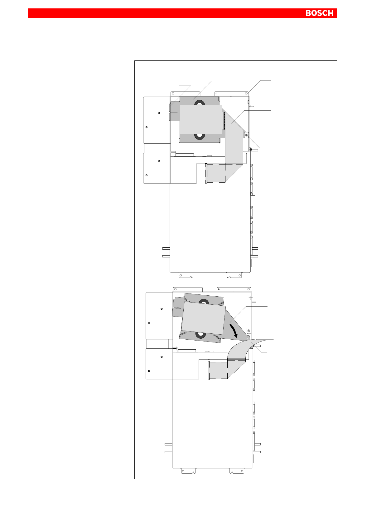
8–4
Maintenance and Replacements
Removing the Hard Disk
View: PC pulled down, side facing display
Clamping joints
for fastening the
hard disk holding
fixture
Holding fixture
for hard disk
PC holding fixture
Hard Disk
PC housing
Controller ribbon cable
Mounting screw for
fastening the hard disk
holding fixture
First pull fixture down, then
turn it outwards
Controller ribbon cable
disconnected from hard
disk
1070 073 825-103 (02.04) GB

8.2.2 Display and Backlight/Inverter
CAUTION
Danger to the module!
All ESD protection measures must be observed when using the
module! Prevent electrostatic discharges!
A fading backlight causes a progressive deterioration of LCD display readability, making a backlight replacement advisable. These components should
also be replaced in case of malfunction of the display and inverter.
Maintenance and Replacements
8–5
CPS21: Rear of display (PC housing dismounted)
Plug connector
Inverter cable
Inverter cable
4 fastening
screws
(LCD mounting
frame)
to the LCD connector
(motherboard of the
PC)
Fastening
screws for
PC housing
Fastening
screw for safety chain
LCD
ribbon cable
Display
(rear)
LCD
mounting frame
1070 073 825-103 (02.04) GB
1. Switch off the supply voltage. If necessary, unplug all cables.
2. Wait until the power supply unit shuts down automatically after UPS operation (the UPS-LED on the front of the CPS21 is red until the UPS shuts
down the power supply unit).
3. Open the aluminum housing with a 5 mm double-bit key and swing the
front panel and its frame to the side.

8–6
Maintenance and Replacements
4. Remove the plug from the PC and all PE connections from the PC housing.
5. The PC is fastened to the upper edge of the plastic frame with 2 screws,
and secured with a safety chain against falling off the frame. Unscrew the
two fastening screws and pull the PC down as far as the safety chain permits.
Replacing the Display/Backlight:
6. Unplug the LCD ribbon cable and the backlight inverter cable from the
LCD mounting frame.
7. Unfasten the safety chain of the PC housing. While doing so, hold the PC.
Remove the PC by lifting it out of the lower swing bearings of the plastic
frame.
8. Unfasten the 4 fastening screws of the LCD mounting frame. Now you
can pull out the display and its holding fixture.
9. It is also possible to replace only the two backlights.
10.Reassemble the components in the reverse sequence to that described
above.
. When remounting the hard disk, make sure that cables, especially
those between display and PC housing, are not flattened or squeezed.
CAUTION
Use only the same type of displays!
Only insert backlights complying with the display!
Testing the new component:
11.In the event that, after booting the system, the display does not produce
an image, check for the following:
D Positive connection of plug connectors and cables
D Proper seating and positive contact of backlight unit
1070 073 825-103 (02.04) GB

8.2.3 Rechargeable Battery Pack
CAUTION
Prior to replacing the battery pack, save all important data because
voltage failures which might occur during the process lead to loss
of data in the RAM.
The rechargeable battery pack must be replaced in the following cases:
D the battery test during the start of the system has failed
D the number of charging cycles exceeds the value stated below for am-
bient temperature dependent cycles (see UPS program, page 3–8)
D the red LED ”UPS” on the front panel flashes for more than 8 hours (see
page 7–8).
A recharge cycle is determined by switching the PC power supply unit on and
off.
As long as the control terminal is connected to mains power, a deep discharge of the rechargeable battery pack is prevented.
Maintenance and Replacements
8–7
The number of charging cycles that the rechargeable battery pack can withstand and therefore its useful life, depends on the ambient temperature in
which the battery pack is used. Ambient temperature here is defined as the
one in which the operating terminal is situated, e.g. the temperature in the
control cabinet or in the operating housing.
The following table can be used as a guideline:
Ambient temperature Charging cycles Maintenance interval
+ 25 °C 4000 cycles 6 years
+ 35 °C 2000 cycles 3 years
+ 45 °C 1000 cycles 1.5 years
. If there is some uncertainty concerning the temperature conditions of
the operating terminal, then we recommend exchanging the battery
pack every 1.5 years.
1070 073 825-103 (02.04) GB

8–8
Maintenance and Replacements
Battery
pack
Mounting screws
Rear
PC housing
Mounting screws
Replacing the battery pack
Battery pack
Carrier board
Battery line (two
conductors) for power
supply
Battery
pack
Connectio
n
1. Switch off the supply voltage. If necessary, unplug all cables.
–+
12
X19
2. Wait until the power supply unit shuts down automatically after UPS operation (the UPS-LED on the front of the CPS21 is red until the UPS shuts
down the power supply unit).
3. Open the aluminum housing with a 5 mm double-bit key and swing the
front panel and its frame to the side.
4. Open the rear cover of the PC housing.
5. Remove the male connector with the twin-conductor cable from the X19
battery terminal.
6. Unscrew the battery packs and replace them.
1070 073 825-103 (02.04) GB

Maintenance and Replacements
7. Now reconnect the cable of the new batteries.
CAUTION
In case of false polarity, an F10A (5x20) fuse will be tripped on the
power supply unit. UPS operation is then impossible.
Therefore, ensur e c o r r e c t polarity of the battery packs when connecting the cable (see illustration above).
8. Reassemble the components in the reverse sequence to that described
above.
8–9
. If the new battery pack has not yet been charged (for 2.5 Ah: approx. 5
hours charging time), the UPS protection against an uncontrolled
shutdown of the PC is not sufficient during the charging time. Therefore, use only fully charged batteries if possible.
Testing the new component:
9. Restart the system.
10.Observe the ”UPS” indication on the front panel. If the batteries are al-
ready charged, the UPS-LED is off. If the batteries are not yet fully charged, the UPS-LED flashes red. In this case, please wait for approx. 5
hours until the UPS-LED goes off (batteries are charged).
1070 073 825-103 (02.04) GB

8–10
Notes:
Maintenance and Replacements
1070 073 825-103 (02.04) GB
 Loading...