

Page 1
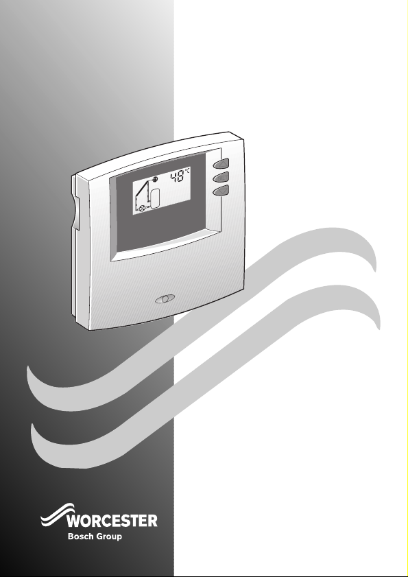
TDS 10
SOLAR SYSTEM CONTROLLE R
FOR WORC ESTER SOLAR H EATIN G SYSTEMS
6 7 2 0 6 1 1 6 7 5 - 0 0 . 1 R
INSTALLATION,
USER INSTRUCTIONS &
CUSTOMER CARE GUIDE
Page 2
Contents
Contents
1 Product details 4
1.1 Intended use 4
1.2 Standard package 4
1.3 Technical data 4
1.4 Description of function 5
1.5 Key to illustrations in
Appendix 6
1.6 Unvented DHW
Cylinders 6
2 Regulations 7
3 Installation 7
3.1 Installing the controller 7
3.2 Installing the
temperature sensors 8
3.3 Electrical connections 8
4 Commissioning 9
5Operation 10
5.1 General information 10
5.2 Controls 10
5.3 Settings 11
5.3.1 Storage tank
temperature limit 11
5.3.2 Manual mode 11
5.3.3 Viewing temperature
readings 11
5.3.4 Power failure 11
6 Maintenance 11
7 Troubleshooting 12
7.1 Faults indicated on the
display 12
7.2 Faults not indicated
on the display 14
Appendix 20
2
6 720 612 217 (05.03)
Page 3
Safety precautions
Safety precautions
B To ensure the equipment functions
properly, always follow the instructions in this manual.
B This accessory may only be fitted by
an approved installer and must not
be commissioned until the solar
heating system has been installed
and filled.
B Always install and commission
equipment in accordance with the
relevant instructions.
Usage
B This accessory should only be used
in conjunction with a solar heating
system. Electrical connections must
be made according to the wiring diagram.
Electrical equipment
B Before installing this accessory:
Disconnect the power supply
(230 V AC).
B Do not install this accessory in damp
areas.
Explosive and easily combustible
materials
B Do not use or store easily combusti-
ble materials, liquids or gases near
to this accessory.
6 720 612 217 (05.03)
Symbols
Safety instructions in this docu-
ment are identified
by a warning-triangle symbol and are
printed on a grey
background.
Signal words indicate the seriousness
of the hazard in terms of the consequences of not following the safety
instructions.
• Caution indicates that minor dam-
age to property could result.
• Warning indicates that minor per-
sonal injury or serious damage to
property could result.
• Danger indicates that serious per-
sonal injury could result. In particularly serious cases, lives could be at
risk.
Notes are identified
by the symbol shown
i
on the left. They are
bordered by horizontal
lines above and below
the text.
Notes contain important information in
cases where there is no risk of personal injury or damage to property.
3
Page 4
Product details
1Product details
The TDS 10 is a controller for use with
thermal solar heating systems that use
heat from the sun to heat a hot water
tank or intermediate heat store.
1.1 Intended use
Th is a cce sso ry may only b e us ed i n th e
types of system specified above.
Any other type of use is beyond the
purpose for which this device is
intended. The manufacturer will not be
liable for any loss or damage resulting
from such use.
1.2 Standard package
• Solar system controller TDS 10.
• 2 PTC-type temperature sensors:
– Solar-panel temperature
sensor.
– Storage tank temperature
sensor for lower tank zone.
4
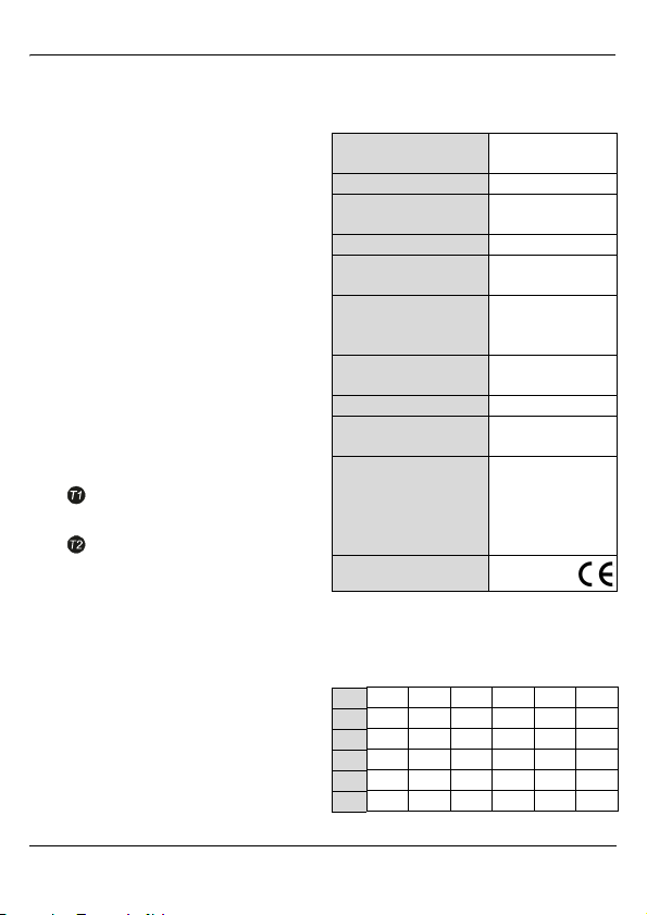
1.3 Technical data
Device dimensions
(LxWxH) 136x133x37 mm
Weight 250 g
Power supply 230 V (±15%)
Power consumption ≤1 W
Temperature-sensor
inputs 2 x PTC
Output for solar
heating system
pump
Permissible ambient
temp.
Internal fuse 4 A MT, 250 V
Ingress Protection
rating
Temperature sensor:
Sensor
Lead (silicon)
Range
Table 1
Temperature sensor readings
(PTC)
°C 0 1020304050
Ω 1000 1039 1078 1117 1155 1194
°C 60 70 80 90 100 110
Ω 1232 1271 1309 1347 1385 1423
°C 120 130 140 150 160 170
Ω 1461 1498 1536 1573 1611 1648
Table 2
50 Hz
230 V AC
max. 800 W
0...+45 °C
IP 20/
DIN 40050
PTC, Ø6 mm
1.5 m
up to 180 °C
6 720 612 217 (05.03)
Page 5
Product details
1.4 Description of function
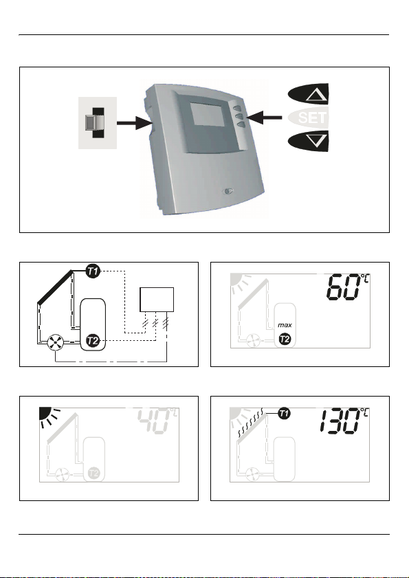
For a simplified diagram of the system,
refer to Figure 2 on page 16.
Temperature differential regulator
The temperature differential regulator
controls the operation of the solar heating system pump.
• The solar heating system pump is
switched on when the difference
between the solar panel temperature and the storage tank temperature exceeds the ON threshold
of
8 K (°C).
The display shows the sun symbol
and the symbol moves (Fig. 3).
• The solar heating system pump is
switched off when the difference
between the solar panel temperature and the storage tank temperature falls below the OFF
threshold of 4 K.
The sun symbol disappears from the
display and the symbol stops
moving (Fig. 3).
ON threshold for solar heating system pump:
- ≥ temperature difference of 8 K
OFF threshold for solar heating system pump:
- ≤ temperature difference of 4 K.
Storage tank temperature limiter
The storage tank temperature limiter
prevents the domestic hot water
becoming too hot:
Normal setting = 60°C.
Warning: Risk of
scalding from storage
tank temperatures
over 60 °C!
B Fit a thermostatic mix-
er to the hot water
draw off pipe and set
to 60 °C max.
Function:
• The solar heating system pump is
switched off if the storage tank temperature sensor reading exceeds
the set temperature. The symbol
stops moving and max flashes
(Fig. 4, page 16).
• The solar heating system pump is
switched on again as soon as the
storage tank temperature drops
below the set temperature limit by
4 K. The symbol moves and max
disappears from the display (Fig. 4,
page 16).
6 720 612 217 (05.03)
5
Page 6
Product details
Solar panel high-temperature cutout (fixed setting)
• Above a temperature of 130 °C at
the solar panel temperature sensor
the solar heating system pump
switches off.
The display shows the hot panel/
evaporation symbol and the symbol stops moving (Fig. 5, page 16).
• The solar heating system pump
does not switch on again until the
solar panel temperature has
dropped below 127 °C and the storage tank temperature sensor
calls for heat.
• At temperatures above 140 °C the
convector fluid evaporates in the
solar panel.
Indication of excessive temperature difference (fixed setting)
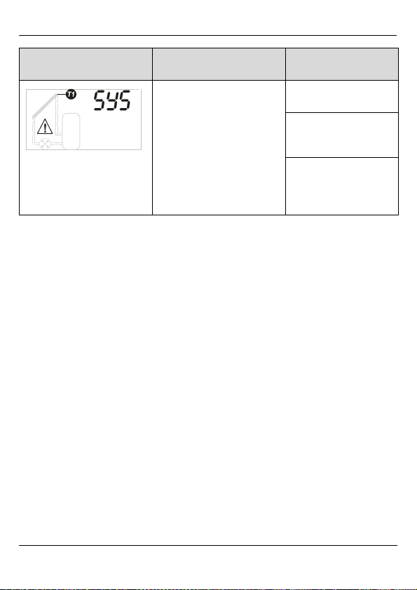
• If the temperature difference -
is greater than 80 K, this can be a
sign that there is air in the system or
that the solar heating system pump
is defective.
Display error message: SYS.
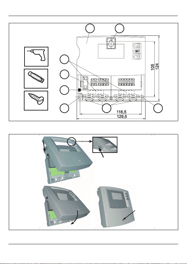
1.5 Key to illustrations in Appendix
Key to Figures 1 to 10 on pages 16
to 18:
Solar heating system pump
Solar panel temperature sensor
(PTC)
Storage tank temperature
sensor (PTC)
1 Top fixing hole
2 Bottom fixing holes
230 V AC Power supply connection
3 Spare fuse, 4 A MT, 250 V
4 Fuse 4 A MT, 250 V
5 Cable exits to rear
6 Cable exits to underneath
7 Inner programmer cover
S Mode selector switch
Si Fuse, 4 A MT, 250 V
TDS 10 Solar heating system
No function
(protects electronics)
programmer
1.6 Unvented DHW Cylinders
When connecting the Greenskie's
Solar Heating System to an un-vented
hot water storage cylinder, it is recommended that the electrical supply to
the solar control system is taken via the
thermal cut-out device on the cylinder.
6
6 720 612 217 (05.03)
Page 7
2 Regulations
This accessory conforms to the relevant EN regulations.
The following regulations and requirements must be observed:
• Requirements and regulations of the
relevant local electricity supplier
• Trade and fire safety requirements
and regulations.
3Installation
Danger: risk of elec-
tric shock!
B Before installing this
accessory:
Disconnect the power supply (230 V AC).
3.1 Installing the controller
When installing the controller, refer to
Figs. 6 and 7 on page 17.
B Select a suitable installation site.
Regulations
The installation of the Worcester Solar
System and controller must be carried
out in accordance with the relevant
requirements for safety, current
IEE wiring regulations, local building
regulations, building standards (Scotland) (Consolidation) regulations,
health and safety document No 635
(Electricity at Work Regulations 1989),
BS 5918: Latest version.
B Insert screw into hole.
B Locate top fixing hole in controller
backplate over screw.
B Mark position of bottom fixing holes.
B Remove controller again.
B Drill bottom fixing holes.
B Relocate programmer over top
screw.
B Insert screws in bottom holes and fix
programmer in position.
B Refit top part of programmer.
The controller can be fitted directly onto cable
i
trunking.
B Remove the top part of the controller
cover.
B Drill the top fixing hole.
6 720 612 217 (05.03)
7
Page 8
Installation
3.2 Installing the tempera-
ture sensors
Use only genuine PTCtype temperature sen-
i
sors (see Section 1.3).
To install immersion sensors and
:
B Insert temperature sensor in the
pocket on the solar panel flow side
and screw in place. The sensor and
lead must be inserted to a depth of
170 mm into the panel and screwed
in tightly.
B Insert temperature sensor in the
lower pocket on the hot water storage tank and fix in place.
3.3 Electrical connections
Danger: risk of elec-
tric shock!
B Before making any
electrical connections, disconnect the
power supply (230 V
AC) to the heating
system.
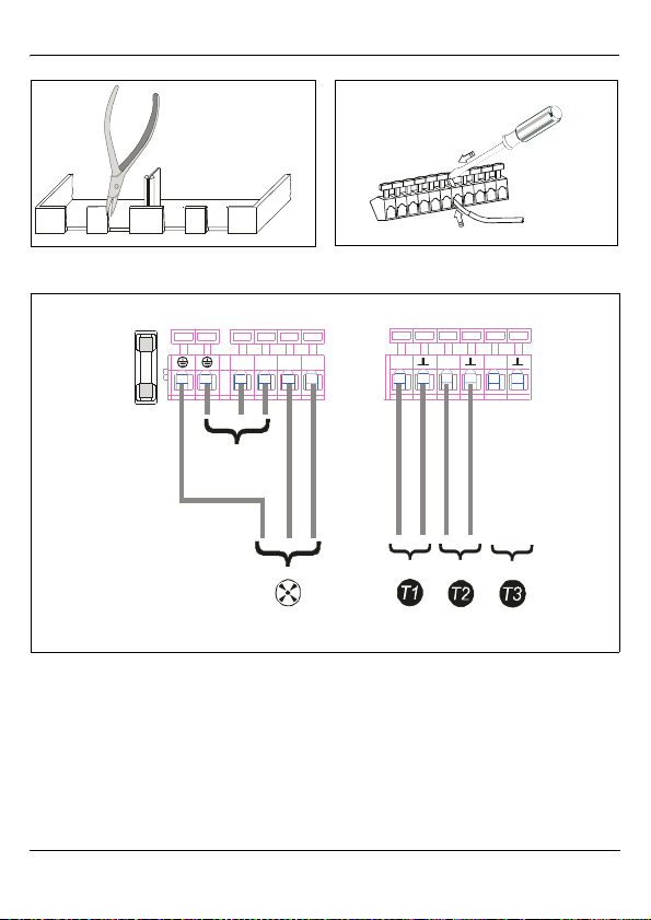
For details of electrical connections,
refer to Figs. 8 to 10 on page 18.
B Sensor leads can be up to 100 m
long. 1.5 m is supplied.
8
B Wiring run lengths and cross-sec-
tional areas for low-voltage wiring:
Length up to 50 m 0.75 mm
Length up to 100 m 1.5 mm
Table 3
B For the 230 V power supply use
general duty, 300-500 V PVC
coated, 0.75 mm
B Route all low-voltage leads sepa-
rately from 230 V or 400 V cables in
order to avoid inductive interference
(minimum separation 100 mm).
B If there is a likelihood of external
inductive interference, e.g. from
high-power cables, tram power
lines, electricity substations, radio
and television equipment, amateur
radio transmitters, microwaves or
the like, shielded low-voltage leads
should be used.
B To ensure the programmer complies
with the IP 20 Ingress Protection rating:
– Only break open as many cable
exits as absolutely necessary.
– Only make the holes just big
enough for the cables used.
– Cable exits to underneath:
Cut a slot on each side with a suitable tool and break off from the
programmer casing (Fig. 8)
or
2
electrical cable.
6 720 612 217 (05.03)
2
2
Page 9
Commissioning
Cable exits to rear:
Break open with a suitable tool
through the programmer casing
backplate (Fig. 6).
On fine wire leads:
i
B Use cable-end
sleeves.
Cable exit to underneath:
B Secure cable with cable grip.
Cable exit to rear:
B Provide means of securing cable
outside programmer casing.
B Use a screwdriver to lock the snap-
fit terminals (Fig. 9).
Maximum lead cross-section 2.5 mm
i
snap-fit terminal.
B Make all electrical connections (see
Fig. 10).
The sensors and
have to be connected be-
i
fore the TDS 10 will function.
2
for each
4 Commissioning
Check that the solar
heating system has
i
been filled and vented
according to the instructions for the solar
panel and the solar
pump station.
B Switch on power supply.
B Set mode selector switch S to auto-
matic mode.
AUT briefly appears on the display
and the controller is set to automatic
mode.
6 720 612 217 (05.03)
9
Page 10
Operation
5Operation
Information to be given
to the user by the in-
i
staller:
B Explain to the user
how to operate the
controller.
B Give the user all the
documents supplied
with the controller.
5.1 General information
The TDS 10 basic settings are
already pre-programmed to suit the
most common applications.
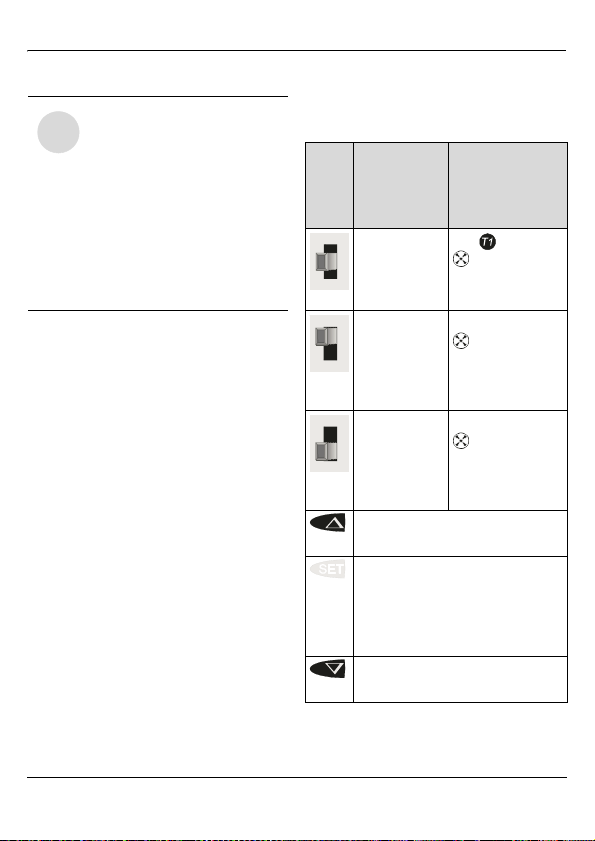
5.2 Controls
For overview of controls, see Fig. 1 on
page 16.
Control
S set to
automatic
mode AUT
S set to
manual
mode, solar
heating
pump ON
S set to
manual
mode, solar
heating
pump OFF
Changes display to next setting or
increases figure
Press and hold: switches to maximum storage tank temperature
setting
Press and release: saves settings
and switches to automatic mode
Changes display to previous setting or reduces figure
Table 4
Description
E.g. 48 °C
moves / stops
Display backlighting yellow
ON flashes
moves
Display backlighting red
OFF flashes
stops
Display backlighting red
Display
Factory
setting
10
6 720 612 217 (05.03)
Page 11
Maintenance
5.3 Settings
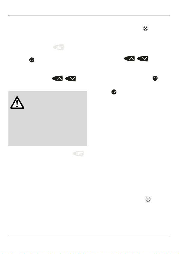
5.3.1 Storage tank temperature limit
B Press and hold the button for
approx. 2 seconds until the flashing
symbol max appears on the display (Fig. 11).
B Set the maximum storage tank tem-
perature using the / buttons.
Warning: Risk of
scalding from storage
tank temperatures
over 60 °C!
B Fit a thermostatic mix-
er to the hot water
draw off pipe and set
to 60 °C max.
B Save setting by pressing the
button.
5.3.2 Manual mode
Switching on the solar heating system
pump, e.g. for commissioning or servicing:
B Set the mode selector switch S to
solar heating pump ON.
– The solar heating system pump
will run continuously.
– The display backlighting is red,
ON flashes and the symbol
moves (Fig. 12).
5.3.3 Viewing temperature readings
B Pressing the / button
allows you to view the following
readings:
– Solar panel temperature
– Storage tank lower-zone tempera-
ture .
5.3.4 Power failure
• None of the settings are lost if there
is a power failure.
• When the power is restored, the
TDS 10 automatically starts working
again according to the set programme.
6 Maintenance
When carrying out maintenance work
on the system:
B Set the mode selector switch S to
solar heating pump OFF.
– The solar heating pump will stop.
– The display backlighting is red,
OFF flashes and the symbol
stops moving (Fig. 13).
B Switch off the power supply.
6 720 612 217 (05.03)
11
Page 12
Troubleshooting
7 Troubleshooting
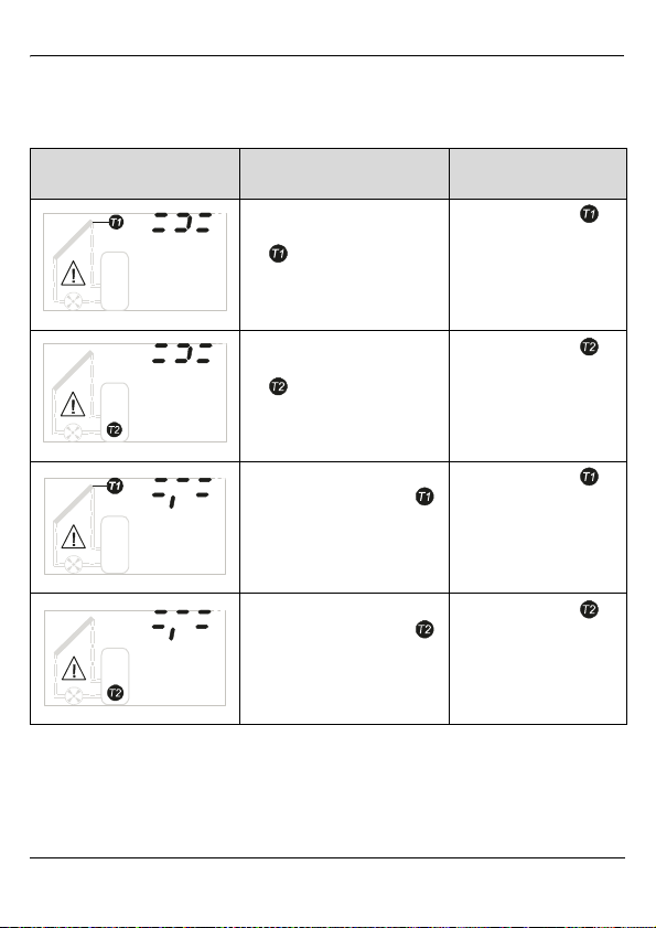
7.1 Faults indicated on the display
Display shows
(flashing red/yellow)
6 720 611 675-11.1J
6 720 611 675-19.1J
6 720 611 675-12.1J
Cause Remedy
Short circuit on sensor lead to
solar panel temperature sensor
Short circuit on sensor lead to
solar panel temperature sensor
Break in sensor lead to solar
panel temperature sensor
Break in sensor lead to solar
panel temperature sensor
Check sensor lead .
Check sensor lead .
Check sensor lead .
Check sensor lead .
Table 5
12
6 720 611 675-20.1J
6 720 612 217 (05.03)
Page 13
Display shows
(flashing red/yellow)
6 720 611 675-13.1J
Cause Remedy
Indication of a fault in the system, e.g. shut-off valves
closed, air in the system or
defective solar heating system
pump.
Table 5
Deleting displayed faults
B To delete a displayed fault, press
any button.
Troubleshooting
Check that the shut-off
valves are open.
Check the system.
If necessary have the system bled.
Check whether the solar
heating system pump is
working (see
Section 5.3.2).
6 720 612 217 (05.03)
13
Page 14
Troubleshooting
7.2 Faults not indicated on the display
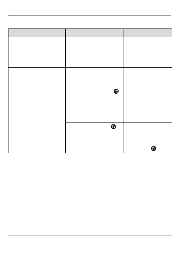
Problem Cause Remedy
Display blank, solar heating
system pump not running even
though storage tank temperature is below solar panel temperature.
Solar heating system pump
not running even though storage tank temperature is below
solar panel temperature.
Table 6
No power supply, fuse blown
or power lead defective.
Solar heating system pump
switched off by mode selector
switch S.
Storage tank temperature
is close to or above the set
maximum storage tank temperature, storage tank temperature limiter has switched off
solar heating system pump.
Solar panel temperature is
above 130°C, solar panel temperature cut-out has switched
off solar heating system pump.
Have electrical system
checked by qualified
electrician.
Set mode selector switch
S to automatic mode.
As soon as the storage
tank has cooled down or
sufficient water is drawn
off, the solar heating system pump will switch on
again.
Solar heating system
pump is not switched on
again until solar panel
temperature has dropped
below 127 °C .
14
6 720 612 217 (05.03)
Page 15
Troubleshooting
Problem Cause Remedy
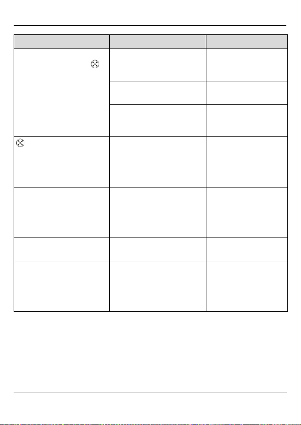
Solar heating system pump
not running even though
symbol on the display is moving.
symbol on display is moving, solar heating system
pump is “humming”.
Temperature sensor shows
incorrect reading.
Domestic hot water too hot Storage tank temperature limit
Domestic hot water not hot
enough (or not enough
domestic hot water).
Break in connecting lead to
solar heating system pump or
lead not connected.
Fuse (SI, Fig. 10) has blown. Check fuse and replace if
Solar heating system pump
defective.
Pump is jammed. Unscrew slotted-head
Temperature sensor not fully
inserted in pocket or excessive
temperature loss at point of
measurement.
set too high.
Hot water temperature control
on boiler or heating programmer is set too low.
Check lead.
necessary.
Check solar heating system pump and replace if
necessary.
bolt from pump cover and
free pump shaft with a
screwdriver. Do not strike
the pump shaft!
Push temperature sensor
all the way into pocket
and fix in position.
Provide insulation if necessary.
Set lower storage tank
temperature limit.
Set temperature according to the relevant operating instructions
(recommended max.
60 °C).
Table 6
6 720 612 217 (05.03)
15
Page 16
Troubleshooting
Appendix
S
Fig. 1
6 720 611 675-06.1J
TDS 10
Fig. 2
Fig. 3
16
6 720 611 675-18.1J
6 720 611 675-14.1J
6 720 611 675-15.1J
Fig. 4
6 720 611 675-16.1J
Fig. 5
6 720 612 217 (05.03)
Page 17
Troubleshooting
Fig. 6
6 mm
6 mm
3,5 mm
1.
7
6 720 611 675-01.1J
5
1
4
3
2
6
2
1.1
3.
6 720 611 675-05.1J
Fig. 7
6 720 612 217 (05.03)
2.
17
Page 18
Troubleshooting
Fig. 8
6 720 611 675-02.1J
Fig. 9
O
1
.
3
0
-
5
7
6
1
1
6
0
2
7
6
Fig. 10
18
Si
6 720 611 675-04.1O
230V AC
L
R1 N
N
E1 E2
E 3
6 720 612 217 (05.03)
Page 19
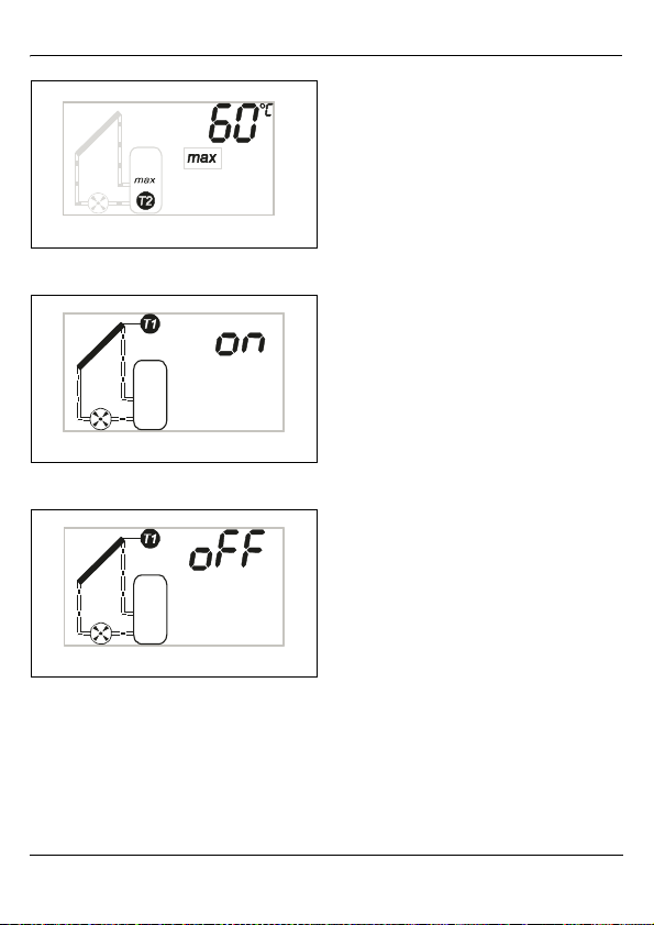
Fig. 11
Fig. 12
Troubleshooting
6 720 611 675-17.1J
6 720 611 675-08.1J
6 720 611 675-09.1J
Fig. 13
6 720 612 217 (05.03)
19
Page 20

INSTALLATION,
USER INSTRUCTIONS &
CUSTOMER CARE GUIDE
Worcester, Bosch Group
Cotswold Way, Warndon, Worcester WR4 9SW.
Tel. 01905 754624 Fax. 01905 754619
www.worcester-bosch.co.uk
Worcester Bosch Group is a trading name of
BBT Thermotechnology UK Ltd.
6 720 612 217 (05/03) OSW
 Loading...