

Bosch Worcester Danesmoor 12/14, Worcester Danesmoor 15/19, Worcester Danesmoor 20/25 Installation And Servicing Instructions

DANESMOOR
SYSTEM BOILER
CONVENTIONAL FLUE AND ROOM SEALED BF
FLOOR STANDING OIL-FIRED PRESSURE JET APPLIANCES
INSTALLATION AND
SERVICING INSTRUCTIONS
BOILER OUTPUT
Hot Water and Central Heating
12/14 MINIMUM 12 kW(41,000 Btu/h)
MAXIMUM 14 kW (48,000 Btu/h)
15/19 MINIMUM 15 kW(51,000 Btu/h)
MAXIMUM 19 kW (65,000 Btu/h)
20/25 MINIMUM 20 kW(68,000 Btu/h)
MAXIMUM 25 kW (85,000 Btu/h)
THESE INSTRUCTIONS APPLY TO UK MODELS ONLY
THESE INSTRUCTIONS ARE TO BE LEFT WITH THE APPLIANCE
All manuals and user guides at all-guides.com
all-guides.com
1.1 General installation information and advice may be obtained
from the Oil Firing Technical Association for the Petroleum
Industry (OFTEC). Training courses are also offered by OFTEC,
leading to inclusion on their list of registered engineers.
1.2 The appliance should be installed by a competent person. The
person installing the appliance should be aware of the Health and
Safety at Work Act and take appropriate action to ensure that the
regulations are adhered to. In order to give optimum efficiency
and trouble free operation the appliance should be commissioned
by a qualified engineer. OFTEC recommends the use of registered
engineers for the commissioning of oil-fired burners.
1.3 The manufacturers notes must not be taken, in any way, as
overriding statutory obligations.
1.4 The compliance with a British Standard does not, of itself,
confer immunity from legal obligations. In particular the installa-
tion of this appliance must be in accordance with the relevant
requirements of the following British Standards and regulations in
respect of the safe installation of equipment.
BS 5410: part 1& 2: Code of practice for Oil Fired Boilers.
BS 799: part 5: Specification for Oil Storage Tanks
BS 7593: Code of practice for treatment of water in domestic hot
water central heating systems.
BS 5449: part 1: Specification for forced circulation hot water
central heating for domestic premises.
BS 5955: part 8: Specification for the installation of
thermoplastic pipes and associated fittings for use in domestic
hot and cold water services and heating systems.
BS 7291: Thermoplastic pipes and associated fittings for hot and
cold water for domestic purposes and heating installations in
buildings.
BS 7074: part 1: Application, selection and installation of expan-
sion vessels and ancillary equipment for sealed water systems.
BS 7671: IEE Wiring Regulations current edition.
The Building Regulations Part J and L1 England and Wales; Part F
Section III and Part J Scotland; Part L and Part F Northern Ireland.
Local water company bye-laws.
The Control of Pollution (Oil) Regulations.
1.5 To ensure that the installation will perform to the highest
standards, the system and components should conform to those
mentioned in the instructions.
The Benchmark initiative is the new code of practice
to encourage the correct installation, commissioning and
servicing of domestic central heating boilers and system
equipment.
The 'Log-book' is a vital document that must be completed
by the installer at the time of installation. It confirms that the
boiler has been installed and commissioned according to the
manufacturers instructions.
Without the completion of the Log-book, manufacturers may refuse
to respond to a call-out from a householder, who will be advised
that he or she must call back the installer, who has not fulfilled his
obligations to record the information required by the initiative.
It is important that:
The services and the system are properly flushed as specified.
The User is clearly instructed on the correct operation of the
appliance.
The benefits of regular servicing are explained - to maintain the
efficiency and extend the life of the appliance.
2.1 These instructions cover both conventional flue (CF)/low-level
discharge (LLD) and room sealed balanced flue (RS) appliances.
2.2 The Worcester Danesmoor range of appliances covered in
these instructions have been designed to serve domestic central
heating and hot water requirements ranging from 12 kW to 25 kW.
2.3 The RS balanced flue appliance forms a fully room sealed
system by surrounding the burner with a unique,fully sealed,
push fit box. This causes the combustion air to be drawn
through a factory sealed air duct formed at the rear and under-
side of the boiler. The sealed burner cover gives excellent
acoustic noise reduction and alleviates the need for an air brick
to be located in the boiler room.
Because the balanced flue system does not rely on the cabinet
panels to form the room seal, combustion readings can be taken
from the flue outlet plate as on a conventional appliance, and the
cabinet panels can be easily removed during installation thereby
preventing any damage.
2.4 The boiler is factory set to the mid range output and can be
altered, if necessary, by adjusting the burner as specified in Tables
2 to 4. The low level discharge and room sealed models are only
suitable for use with 28 second Kerosene heating oil.
NOTE: It is a mandatory requirement of the building
regulations that only 28 second kerosene is used on low level
discharge flues.
2.5 The conventional flue 15-19 and 20-25 models may be
converted to burn 35 second gas oil by changing the nozzle and
burner settings as specified in Tables 3 and 4.
2.6 A colour coordinated twin channel programmer can be fitted
to the appliance facia panel. This is available from Worcester Heat
Systems as an optional extra.
2.7 Principle appliance components. See Figs. 2 and 3.
Oil Fired Burner
A fully automatic oil fired pressure jet burner is used to supply
heat to the boiler. The burner can be set to the output require-
ments as detailed in Tables 2 to 4.
Pump
An integral circulating pump is incorporated within the appliance
casing. The pump speed may be altered to suit the heating load by
2. General Information
1. Installation Regulations
2
1. Installation Regulations...........................................Page 2
2. General Information .................................................Page 2
3. Technical Data...........................................................Page 3
4. Siting the Appliance.................................................Page 5
5. Removal of the Cabinet............................................Page 5
6. Air Supply..................................................................Page 5
7. Flue System...............................................................Page 8
8. Oil Supply..................................................................Page 11
9. Heating and Hot Water System...............................Page 13
10. Electrical....................................................................Page 15
11. Installation ................................................................Page 19
12. Commissioning .........................................................Page 20
13. Instructions to the User...........................................Page 23
14. Routine Cleaning and Inspection............................Page 23
15. Fault Finding.............................................................Page 25
16. Short Parts List..........................................................Page 26
Contents
All manuals and user guides at all-guides.com
3
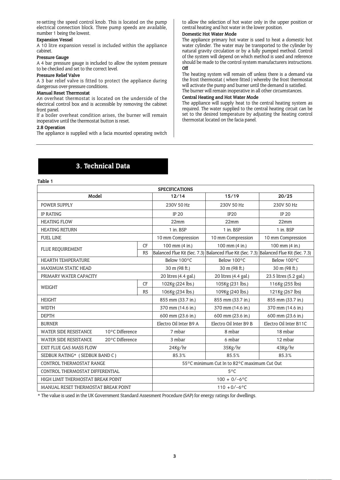
3. Technical Data
re-setting the speed control knob. This is located on the pump
electrical connection block. Three pump speeds are available,
number 1 being the lowest.
Expansion Vessel
A 10 litre expansion vessel is included within the appliance
cabinet.
Pressure Gauge
A 4 bar pressure gauge is included to allow the system pressure
to be checked and set to the correct level.
Pressure Relief Valve
A 3 bar relief valve is fitted to protect the appliance during
dangerous over-pressure conditions.
Manual Reset Thermostat
An overheat thermostat is located on the underside of the
electrical control box and is accessible by removing the cabinet
front panel.
If a boiler overheat condition arises, the burner will remain
inoperative until the thermostat button is reset.
2.8 Operation
The appliance is supplied with a facia mounted operating switch
to allow the selection of hot water only in the upper position or
central heating and hot water in the lower position.
Domestic Hot Water Mode
The appliance primary hot water is used to heat a domestic hot
water cylinder. The water may be transported to the cylinder by
natural gravity circulation or by a fully pumped method. Control
of the system will depend on which method is used and reference
should be made to the control system manufacturers instructions.
Off
The heating system will remain off unless there is a demand via
the frost thermostat ( where fitted ) whereby the frost thermostat
will activate the pump and burner until the demand is satisfied.
The burner will remain inoperative in all other circumstances.
Central Heating and Hot Water Mode
The appliance will supply heat to the central heating system as
required. The water supplied to the central heating circuit can be
set to the desired temperature by adjusting the heating control
thermostat located on the facia panel.
SPECIFICATIONS
Model 12/14 15/19 20/25
POWER SUPPLY 230V 50 Hz 230V 50 Hz 230V 50 Hz
IP RATING IP 20 IP20 IP 20
HEATING FLOW 22mm 22mm 22mm
HEATING RETURN 1 in. BSP 1 in. BSP 1 in. BSP
FUEL LINE 10 mm Compression 10 mm Compression 10 mm Compression
FLUE REQUIREMENT
CF 100 mm (4 in.) 100 mm (4 in.) 100 mm (4 in.)
RS Balanced Flue Kit (Sec. 7.3) Balanced Flue Kit (Sec. 7.3) Balanced Flue Kit (Sec. 7.3)
HEARTH TEMPERATURE Below 100°C Below 100°C Below 100°C
MAXIMUM STATIC HEAD 30 m (98 ft.) 30 m (98 ft.) 30 m (98 ft.)
PRIMARY WATER CAPACITY 20 litres (4.4 gal.) 20 litres (4.4 gal.) 23.5 litres (5.2 gal.)
WEIGHT
CF 102Kg (224 lbs.) 105Kg (231 lbs.) 116Kg (255 lbs)
RS 106Kg (234 lbs.) 109Kg (240 lbs.) 121Kg (267 lbs)
HEIGHT 855 mm (33.7 in.) 855 mm (33.7 in.) 855 mm (33.7 in.)
WIDTH 370 mm (14.6 in.) 370 mm (14.6 in.) 370 mm (14.6 in.)
DEPTH 600 mm (23.6 in.) 600 mm (23.6 in.) 600 mm (23.6 in.)
BURNER Electro Oil Inter B9 A Electro Oil Inter B9 B Electro Oil Inter B11C
WATER SIDE RESISTANCE 10°C Difference 7 mbar 8 mbar 18 mbar
WATER SIDE RESISTANCE 20°C Difference 3 mbar 6 mbar 12 mbar
EXIT FLUE GAS MASS FLOW 24Kg/hr 35Kg/hr 43Kg/hr
SEDBUK RATING* ( SEDBUK BAND C ) 85.3% 85.5% 85.3%
CONTROL THERMOSTAT RANGE 55°C minimum Cut In to 82°C maximum Cut Out
CONTROL THERMOSTAT DIFFERENTIAL 5°C
HIGH LIMIT THERMOSTAT BREAK POINT 100 + 0/–6°C
MANUAL RESET THERMOSTAT BREAK POINT 110 +0/–6°C
Table 1
* The value is used in the UK Government Standard Assesment Procedure (SAP) for energy ratings for dwellings.
All manuals and user guides at all-guides.com
4
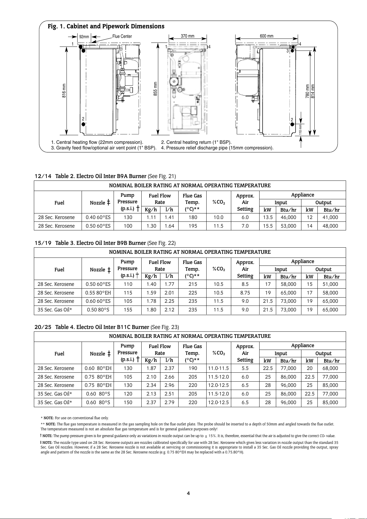
* NOTE: For use on conventional flue only.
** NOTE: The flue gas temperature is measured in the gas sampling hole on the flue outlet plate. The probe should be inserted to a depth of 50mm and angled towards the flue outlet.
The temperature measured is not an absolute flue gas temperature and is for general guidance purposes only!
NOTE: The pump pressure given is for general guidance only as variations in nozzle output can be up to ± 15%. It is, therefore, essential that the air is adjusted to give the correct CO
2
value.
NOTE: The nozzle type used on 28 Sec. Kerosene outputs are nozzles calibrated specifically for use with 28 Sec. Kerosene which gives less variation in nozzle output than the standard 35
Sec. Gas Oil nozzles. However, if a 28 Sec. Kerosene nozzle is not available at servicing or commissioning it is appropriate to install a 35 Sec. Gas Oil nozzle providing the output, spray
angle and pattern of the nozzle is the same as the 28 Sec. Kerosene nozzle (e.g. 0.75 80°EH may be replaced with a 0.75.80°H).
28 Sec. Kerosene 0.40 60°ES 130 1.11 1.41 180 10.0 6.0 13.5 46,000 12 41,000
28 Sec. Kerosene 0.50 60°ES 100 1.30 1.64 195 11.5 7.0 15.5 53,000 14 48,000
NOMINAL BOILER RATING AT NORMAL OPERATING TEMPERATURE
12/14 Table 2. Electro Oil Inter B9A Burner (See Fig. 21)
Fuel Nozzle
Pump
Pressure
(p.s.i.)
Fuel Flow
Rate
Flue Gas
Temp.
(°C)**
%CO
2
Approx.
Air
Setting
Appliance
Input
kW Btu/hr kW Btu/hr
Output
Kg/h l/h
28 Sec. Kerosene 0.50 60°ES 110 1.40 1.77 215 10.5 8.5 17 58,000 15 51,000
28 Sec. Kerosene 0.55 80°EH 115 1.59 2.01 225 10.5 8.75 19 65,000 17 58,000
28 Sec. Kerosene 0.60 60°ES 105 1.78 2.25 235 11.5 9.0 21.5 73,000 19 65,000
35 Sec. Gas Oil* 0.50 80°S 155 1.80 2.12 235 11.5 9.0 21.5 73,000 19 65,000
NOMINAL BOILER RATING AT NORMAL OPERATING TEMPERATURE
15/19 Table 3. Electro Oil Inter B9B Burner (See Fig. 22)
Fuel Nozzle
Pump
Pressure
(p.s.i.)
Fuel Flow
Rate
Flue Gas
Temp.
(°C)**
%CO
2
Approx.
Air
Setting
Appliance
Input
kW Btu/hr kW Btu/hr
Output
Kg/h l/h
28 Sec. Kerosene 0.60 80°EH 130 1.87 2.37 190 11.0-11.5 5.5 22.5 77,000 20 68,000
28 Sec. Kerosene 0.75 80°EH 105 2.10 2.66 205 11.5-12.0 6.0 25 86,000 22.5 77,000
28 Sec. Kerosene 0.75 80°EH 130 2.34 2.96 220 12.0-12.5 6.5 28 96,000 25 85,000
35 Sec. Gas Oil* 0.60 80°S 120 2.13 2.51 205 11.5-12.0 6.0 25 86,000 22.5 77,000
35 Sec. Gas Oil* 0.60 80°S 150 2.37 2.79 220 12.0-12.5 6.5 28 96,000 25 85,000
NOMINAL BOILER RATING AT NORMAL OPERATING TEMPERATURE
20/25 Table 4. Electro Oil Inter B11C Burner (See Fig. 23)
Fuel Nozzle
Pump
Pressure
(p.s.i.)
Fuel Flow
Rate
Flue Gas
Temp.
(°C)**
%CO
2
Approx.
Air
Setting
Appliance
Input
kW Btu/hr kW Btu/hr
Output
Kg/h l/h
Fig. 1. Cabinet and Pipework Dimensions
1
2
4
3
2
816 mm
814 mm
780 mm
110 mm
600 mm
41
370 mm
855 mm
1. Central heating flow (22mm compression). 2. Central heating return (1" BSP).
3. Gravity feed flow/optional air vent point (1" BSP). 4. Pressure relief discharge pipe (15mm compression).
92mm
Flue Center
All manuals and user guides at all-guides.com
4.1 The appliance is not suitable for external installation unless
a suitable enclosure is provided.
4.2 The appliance should be positioned on a non-combustible
solid base as near to the flue location point as possible. Care
should be taken to ensure that the appliance is level; use
packing at the corners where necessary.
4.3 When fitting a LLD or RS model, the rear of the appliance
must be positioned against an external wall such that the flue
terminal can safely discharge the flue gases as described in
Section 7.
4.4 The following clearances must be left to allow access for
installation and servicing:
(a) Above - 300mm
(b) In front - 600mm
(c) Right and left hand side – sufficient for panel
removal and access to pipe connections where
required.
See Figs. 2 and 3.
For installation and servicing of the appliance the cabinet should
be removed as follows:
5.1 Remove the cabinet top panel by lifting squarely upwards to
release the four ball stud connections.
5.2 Remove the front panel by pulling the bottom of the panel
forwards to release the ball studs and lifting the panel upwards
and forwards to release from its supporting ledge.
5.3 The side panels are removed by firstly following procedures
5.1 to 5.2 as described above, then remove screw (A) from the
side panel base and the three screws located in the upper flange
of each side panel. Ease the panel clear of the electrical control
box and slide forwards to release from the locating lugs on the
base plate.
5.4 The control box can be removed by undoing the four screws
in the top access cover and then removing the wing nut on the
underside of the control box. The thermostat phials should be
carefully removed from the phial pocket and the control box
placed in a safe place taking care not to kink the thermostat
capillary tubes.
5.5 On the RS balanced flue model, remove the burner box
cover by pulling forwards to release the ball studs. This will be
found easier by pulling on one side of the handle first to release
two of the ball studs and then repeating on the other side. Take
care not to pivot the remaining two ball studs too far around as
this will cause damage to the spring clips.
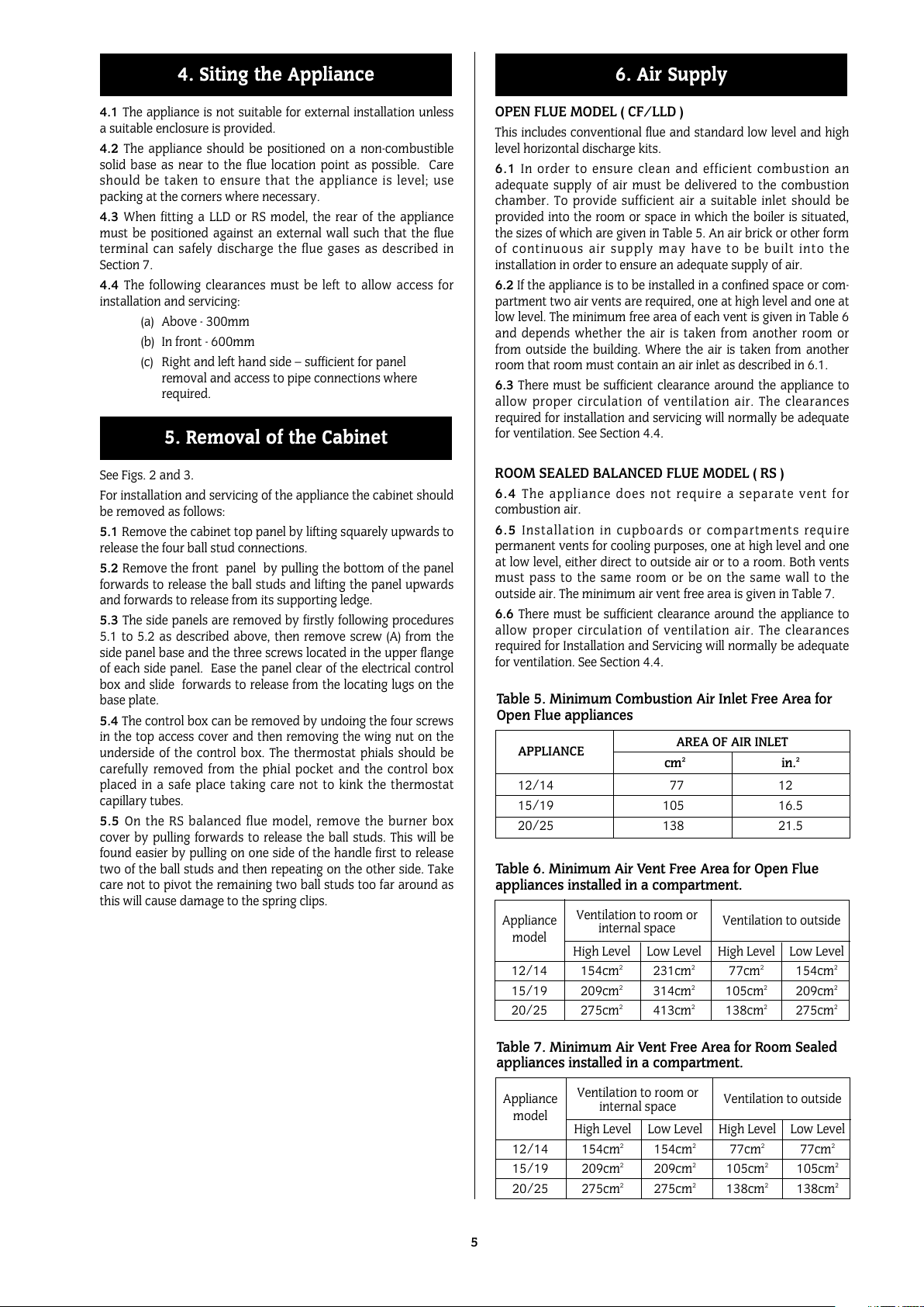
OPEN FLUE MODEL ( CF/LLD )
This includes conventional flue and standard low level and high
level horizontal discharge kits.
6.1 In order to ensure clean and efficient combustion an
adequate supply of air must be delivered to the combustion
chamber. To provide sufficient air a suitable inlet should be
provided into the room or space in which the boiler is situated,
the sizes of which are given in Table 5. An air brick or other form
of continuous air supply may have to be built into the
installation in order to ensure an adequate supply of air.
6.2 If the appliance is to be installed in a confined space or com-
partment two air vents are required, one at high level and one at
low level. The minimum free area of each vent is given in Table 6
and depends whether the air is taken from another room or
from outside the building. Where the air is taken from another
room that room must contain an air inlet as described in 6.1.
6.3 There must be sufficient clearance around the appliance to
allow proper circulation of ventilation air. The clearances
required for installation and servicing will normally be adequate
for ventilation. See Section 4.4.
ROOM SEALED BALANCED FLUE MODEL ( RS )
6.4 The appliance does not require a separate vent for
combustion air.
6.5 Installation in cupboards or compartments require
permanent vents for cooling purposes, one at high level and one
at low level, either direct to outside air or to a room. Both vents
must pass to the same room or be on the same wall to the
outside air. The minimum air vent free area is given in Table 7.
6.6 There must be sufficient clearance around the appliance to
allow proper circulation of ventilation air. The clearances
required for Installation and Servicing will normally be adequate
for ventilation. See Section 4.4.
6. Air Supply
5. Removal of the Cabinet
4. Siting the Appliance
5
Table 6. Minimum Air Vent Free Area for Open Flue
appliances installed in a compartment.
Appliance
Ventilation to room or
Ventilation to outside
model
internal space
High Level Low Level High Level Low Level
12/14 154cm
2
231cm
2
77cm
2
154cm
2
15/19 209cm
2
314cm
2
105cm2209cm
2
20/25 275cm
2
413cm
2
138cm2275cm
2
Table 7. Minimum Air Vent Free Area for Room Sealed
appliances installed in a compartment.
Appliance
Ventilation to room or
Ventilation to outside
model
internal space
High Level Low Level High Level Low Level
12/14 154cm
2
154cm
2
77cm
2
77cm
2
15/19 209cm
2
209cm
2
105cm2105cm
2
20/25 275cm
2
275cm
2
138cm2138cm
2
APPLIANCE
AREA OF AIR INLET
cm
2
in.
2
12/14 77 12
15/19 105 16.5
20/25 138 21.5
Table 5. Minimum Combustion Air Inlet Free Area for
Open Flue appliances
All manuals and user guides at all-guides.com
6
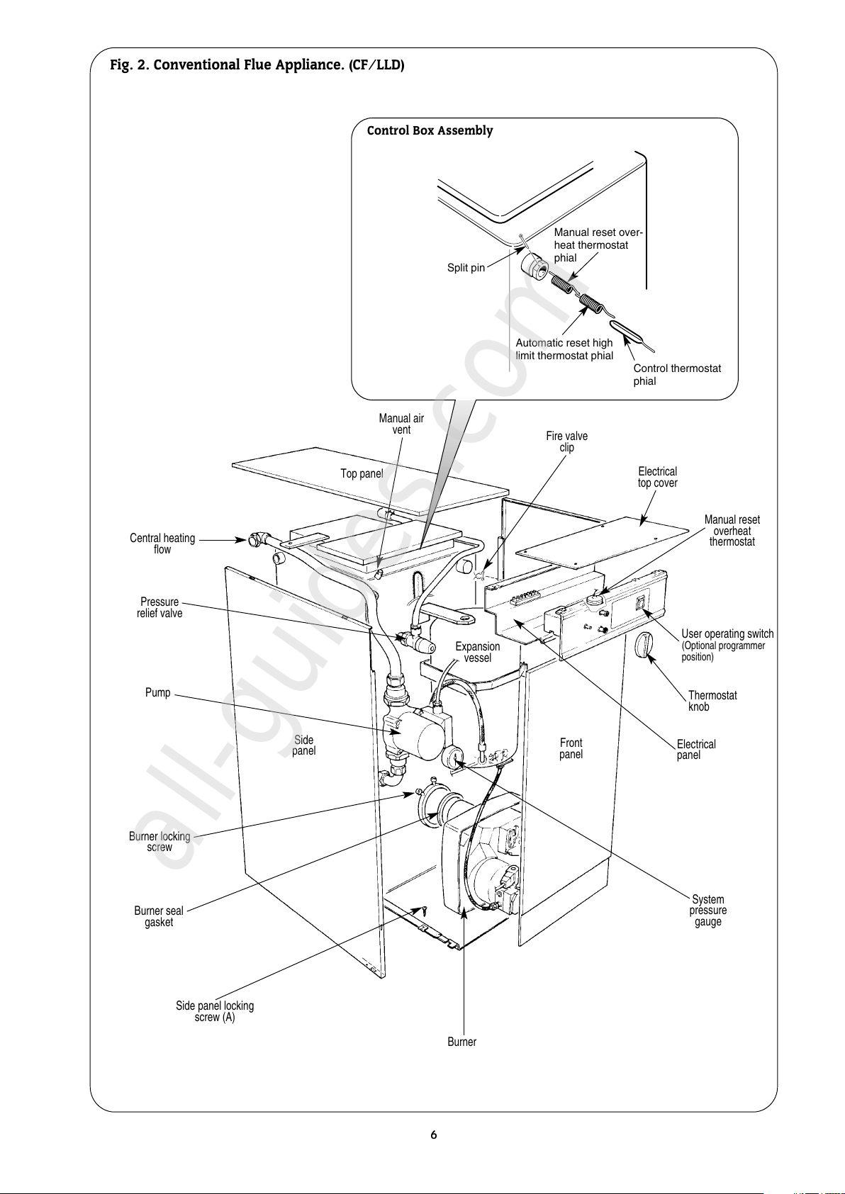
Fig. 2. Conventional Flue Appliance. (CF/LLD)
Manual air
vent
Electrical
top cover
Manual reset
overheat
thermostat
System
pressure
gauge
Side
panel
Side panel locking
screw (A)
Burner seal
gasket
Burner locking
screw
Pressure
relief valve
Central heating
flow
Pump
Burner
Front
panel
Expansion
vessel
Electrical
panel
User operating switch
(Optional programmer
position)
Top panel
Thermostat
knob
Fire valve
clip
Manual reset over-
heat thermostat
phial
Automatic reset high
limit thermostat phial
Control thermostat
phial
Split pin
Control Box Assembly
All manuals and user guides at all-guides.com
all-guides.com
7
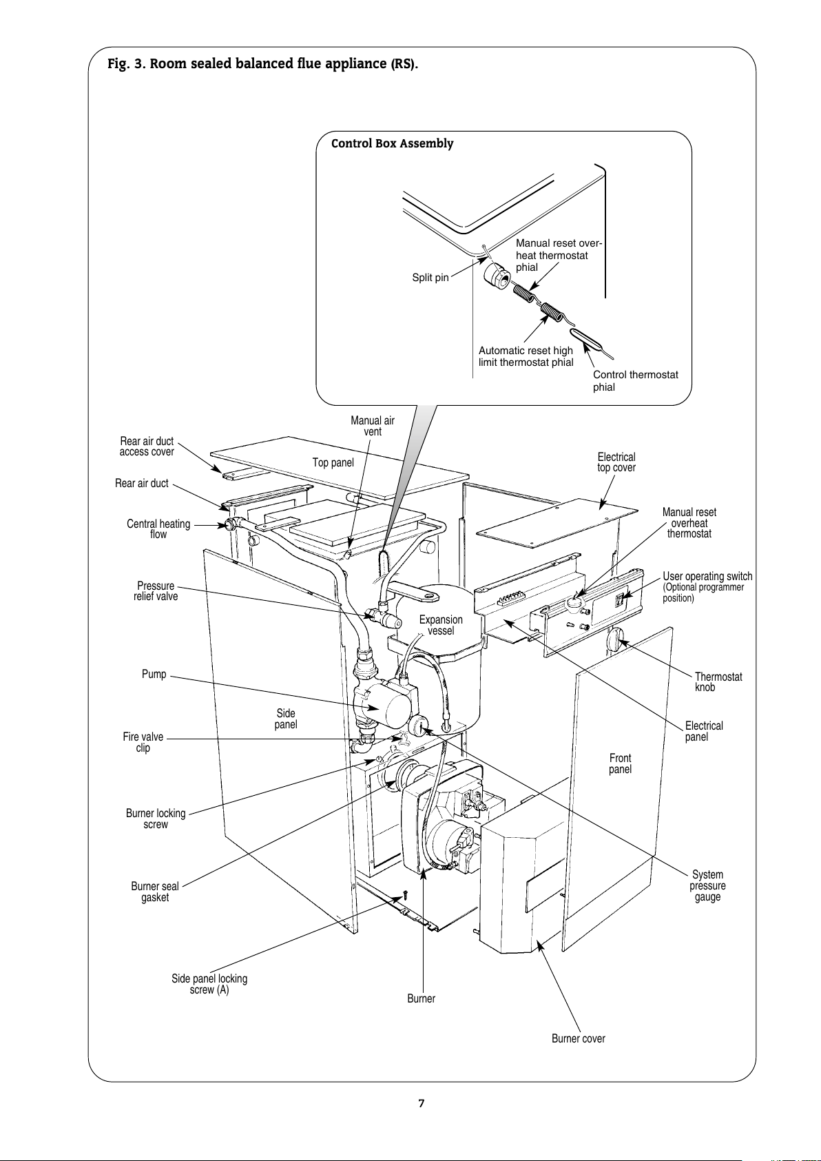
Fig. 3. Room sealed balanced flue appliance (RS).
Manual air
vent
Electrical
top cover
Manual reset
overheat
thermostat
System
pressure
gauge
Side
panel
Side panel locking
screw (A)
Burner seal
gasket
Burner locking
screw
Pressure
relief valve
Central heating
flow
Pump
Burner
Front
panel
Expansion
vessel
Electrical
panel
User operating switch
(Optional programmer
position)
Top panel
Thermostat
knob
Fire valve
clip
Burner cover
Rear air duct
Rear air duct
access cover
Manual reset over-
heat thermostat
phial
Automatic reset high
limit thermostat phial
Control thermostat
phial
Split pin
Control Box Assembly
All manuals and user guides at all-guides.com
A flue system must be provided in accordance with BS5410:Part 1 and
the current Building Regulations.
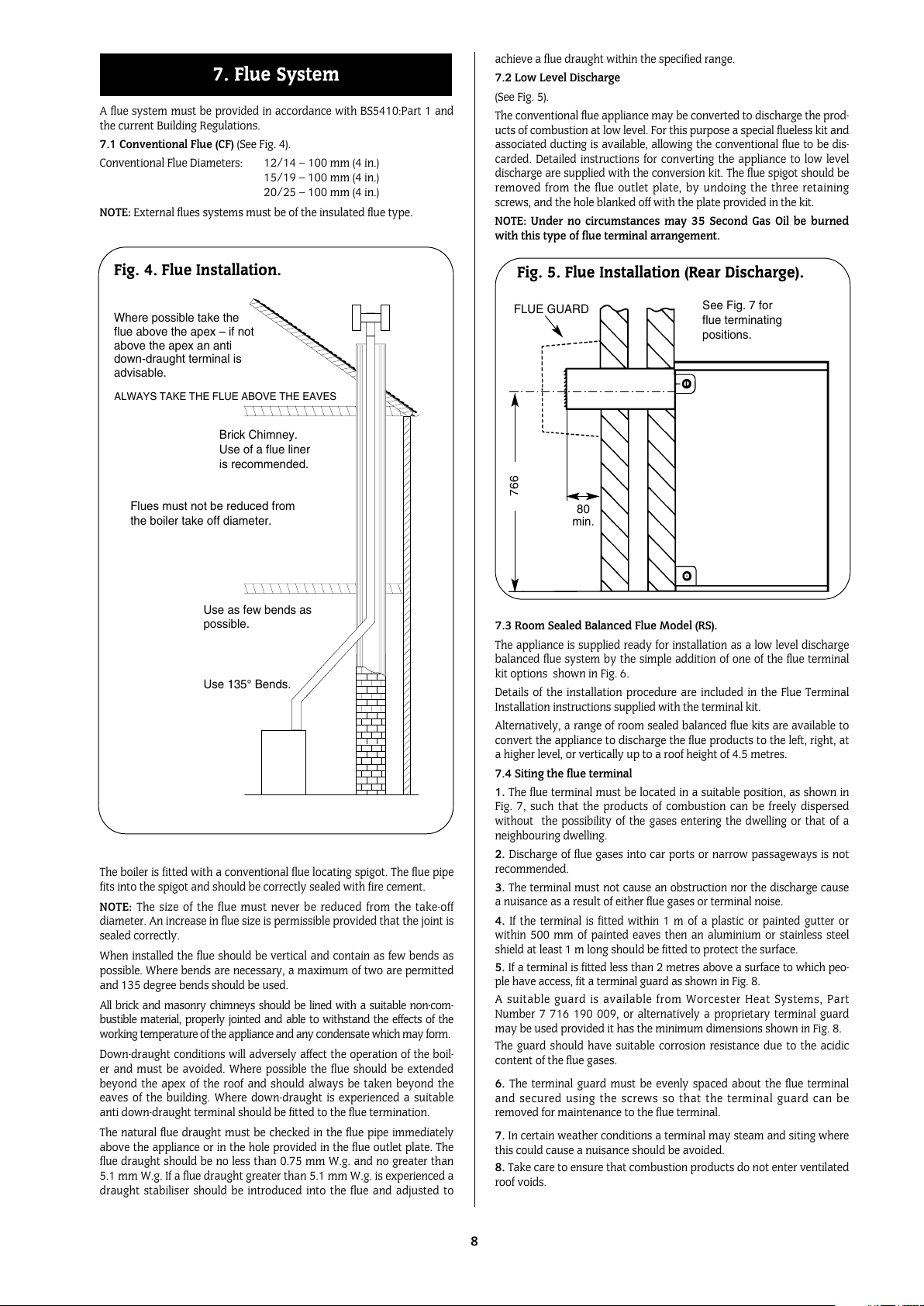
7.1 Conventional Flue (CF) (See Fig. 4).
Conventional Flue Diameters: 12/14 – 100 mm (4 in.)
15/19 – 100 mm (4 in.)
20/25 – 100 mm (4 in.)
NOTE: External flues systems must be of the insulated flue type.
The boiler is fitted with a conventional flue locating spigot. The flue pipe
fits into the spigot and should be correctly sealed with fire cement.
NOTE: The size of the flue must never be reduced from the take-off
diameter. An increase in flue size is permissible provided that the joint is
sealed correctly.
When installed the flue should be vertical and contain as few bends as
possible. Where bends are necessary, a maximum of two are permitted
and 135 degree bends should be used.
All brick and masonry chimneys should be lined with a suitable non-com-
bustible material, properly jointed and able to withstand the effects of the
working temperature of the appliance and any condensate which may form.
Down-draught conditions will adversely affect the operation of the boil-
er and must be avoided. Where possible the flue should be extended
beyond the apex of the roof and should always be taken beyond the
eaves of the building. Where down-draught is experienced a suitable
anti down-draught terminal should be fitted to the flue termination.
The natural flue draught must be checked in the flue pipe immediately
above the appliance or in the hole provided in the flue outlet plate. The
flue draught should be no less than 0.75 mm W.g. and no greater than
5.1 mm W.g. If a flue draught greater than 5.1 mm W.g. is experienced a
draught stabiliser should be introduced into the flue and adjusted to
achieve a flue draught within the specified range.
7.2 Low Level Discharge
(See Fig. 5).
The conventional flue appliance may be converted to discharge the prod-
ucts of combustion at low level. For this purpose a special flueless kit and
associated ducting is available, allowing the conventional flue to be dis-
carded. Detailed instructions for converting the appliance to low level
discharge are supplied with the conversion kit. The flue spigot should be
removed from the flue outlet plate, by undoing the three retaining
screws, and the hole blanked off with the plate provided in the kit.
NOTE: Under no circumstances may 35 Second Gas Oil be burned
with this type of flue terminal arrangement.
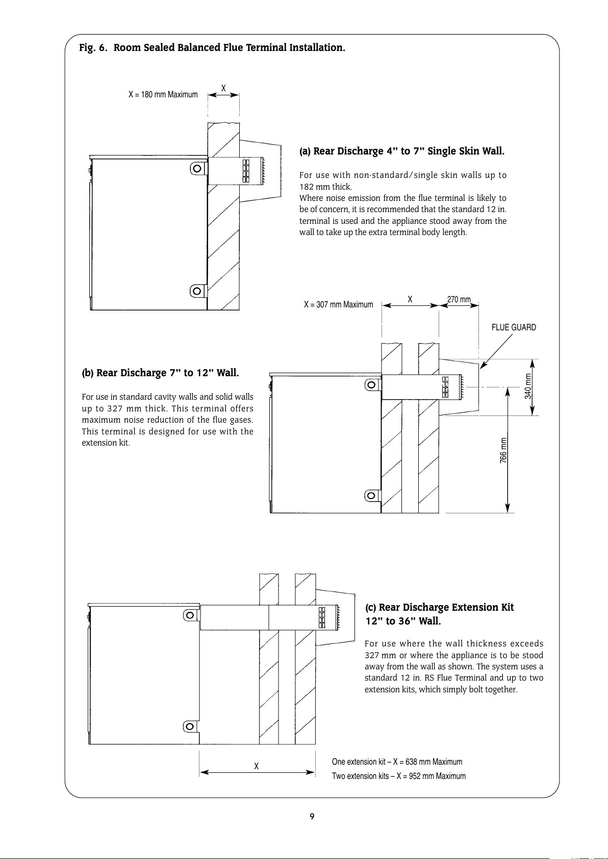
7.3 Room Sealed Balanced Flue Model (RS).
The appliance is supplied ready for installation as a low level discharge
balanced flue system by the simple addition of one of the flue terminal
kit options shown in Fig. 6.
Details of the installation procedure are included in the Flue Terminal
Installation instructions supplied with the terminal kit.
Alternatively, a range of room sealed balanced flue kits are available to
convert the appliance to discharge the flue products to the left, right, at
a higher level, or vertically up to a roof height of 4.5 metres.
7.4 Siting the flue terminal
1. The flue terminal must be located in a suitable position, as shown in
Fig. 7, such that the products of combustion can be freely dispersed
without the possibility of the gases entering the dwelling or that of a
neighbouring dwelling.
2. Discharge of flue gases into car ports or narrow passageways is not
recommended.
3. The terminal must not cause an obstruction nor the discharge cause
a nuisance as a result of either flue gases or terminal noise.
4. If the terminal is fitted within 1 m of a plastic or painted gutter or
within 500 mm of painted eaves then an aluminium or stainless steel
shield at least 1 m long should be fitted to protect the surface.
5. If a terminal is fitted less than 2 metres above a surface to which peo-
ple have access, fit a terminal guard as shown in Fig. 8.
A suitable guard is available from Worcester Heat Systems, Part
Number 7 716 190 009, or alternatively a proprietary terminal guard
may be used provided it has the minimum dimensions shown in Fig. 8.
The guard should have suitable corrosion resistance due to the acidic
content of the flue gases.
6. The terminal guard must be evenly spaced about the flue terminal
and secured using the screws so that the terminal guard can be
removed for maintenance to the flue terminal.
7. In certain weather conditions a terminal may steam and siting where
this could cause a nuisance should be avoided.
8. Take care to ensure that combustion products do not enter ventilated
roof voids.
7. Flue System
8
Fig. 5. Flue Installation (Rear Discharge).
See Fig. 7 for
flue terminating
positions.
80
min.
FLUE GUARD
766
Fig. 4. Flue Installation.
Where possible take the
flue above the apex – if not
above the apex an anti
down-draught terminal is
advisable.
Brick Chimney.
Use of a flue liner
is recommended.
Use as few bends as
possible.
Use 135° Bends.
Flues must not be reduced from
the boiler take off diameter.
ALWAYS TAKE THE FLUE ABOVE THE EAVES
All manuals and user guides at all-guides.com
9
FLUE GUARD
X = 180 mm Maximum
X = 307 mm Maximum
One extension kit – X = 638 mm Maximum
Two extension kits – X = 952 mm Maximum
766 mm
X
X
340 mm
270 mm
Fig. 6. Room Sealed Balanced Flue Terminal Installation.
(b) Rear Discharge 7" to 12" Wall.
For use in standard cavity walls and solid walls
up to 327 mm thick. This terminal offers
maximum noise reduction of the flue gases.
This terminal is designed for use with the
extension kit.
(a) Rear Discharge 4" to 7" Single Skin Wall.
For use with non-standard/single skin walls up to
182.mm thick.
Where noise emission from the flue terminal is likely to
be of concern, it is recommended that the standard 12 in.
terminal is used and the appliance stood away from the
wall to take up the extra terminal body length.
(c) Rear Discharge Extension Kit
12" to 36" Wall.
X
For use where the wall thickness exceeds
327.mm or where the appliance is to be stood
away from the wall as shown. The system uses a
standard 12 in. RS Flue Terminal and up to two
extension kits, which simply bolt together.
All manuals and user guides at all-guides.com
 Loading...