

Bosch WH36, TRONIC 5000C Pro WH36 Installation Manual And Operating Instructions
[en] Installation Manual and Operating Instructions 2
[es] Instrucciones de instalación y funcionamiento 21
[fr] Instructions d'installation et d'utilisation 41
Tankless Electric Water Heaters
TRONIC 5000C Pro
6720647022-00.1V
WH36
6 720 647 022 (2013/04) US
IMPORTANT: This booklet should be given to the customer after installation and demonstration.
For Service & Installation contact:
BOSCH Thermotechnology Corp.
50 Wentworth Avenue, Londonderry
NH 03053
Phone: 800-798-8161
www.bosch-climate.us

6 720 647 022 (2013/04) Tronic 5000C
2 | Table of contents
Table of contents
1 Key to symbols and safety instructions . . . . . . . . . . 2
1.1 Key to symbols . . . . . . . . . . . . . . . . . . . . . . . . 2
1.2 Safety precautions . . . . . . . . . . . . . . . . . . . . 3
2 Information about the heater . . . . . . . . . . . . . . . . . . . 3
2.1 Disclaimer . . . . . . . . . . . . . . . . . . . . . . . . . . . 3
2.2 Technical identification code . . . . . . . . . . . . 3
2.3 Model name and number identification . . . . 3
2.4 Package contents . . . . . . . . . . . . . . . . . . . . . 3
2.5 Components Diagram . . . . . . . . . . . . . . . . . . 4
2.6 Dimensions . . . . . . . . . . . . . . . . . . . . . . . . . . 5
2.7 Wiring diagram . . . . . . . . . . . . . . . . . . . . . . . 6
2.8 Description of the heater . . . . . . . . . . . . . . . 6
2.9 Technical specifications . . . . . . . . . . . . . . . . 7
3 Regulations . . . . . . . . . . . . . . . . . . . . . . . . . . . . . . . . . . 7
4 Installation . . . . . . . . . . . . . . . . . . . . . . . . . . . . . . . . . . 8
4.1 Important information . . . . . . . . . . . . . . . . . . 8
4.2 Selection of place of installation . . . . . . . . . . 8
4.3 Mounting the water heater . . . . . . . . . . . . . . 9
4.4 Water connections . . . . . . . . . . . . . . . . . . . 10
4.5 Electrical connections . . . . . . . . . . . . . . . . . 10
4.6 Starting up . . . . . . . . . . . . . . . . . . . . . . . . . . 13
5 Operation instructions . . . . . . . . . . . . . . . . . . . . . . . 14
5.1 Before using the water heater . . . . . . . . . . 14
6 Maintenance . . . . . . . . . . . . . . . . . . . . . . . . . . . . . . . . 14
7 Troubleshooting . . . . . . . . . . . . . . . . . . . . . . . . . . . . . 16
8 Spare Parts . . . . . . . . . . . . . . . . . . . . . . . . . . . . . . . . . 19
1 Key to symbols and safety
instructions
1.1 Key to symbols
Warnings
The following keywords are defined and can be used in this
document:
• NOTICE indicates a situation that could result in damage to
property or equipment.
• CAUTION indicates a situation that could result in minor to
medium injury.
• WARNING indicates a situation that could result in severe
injury or death.
• DANGER indicates a situation that will result in severe
injury or death.
Important information
Additional symbols
Warnings in this document are identified by
a warning triangle printed against a grey
background.
Keywords at the start of a warning indicate
the type and seriousness of the ensuing risk
if measures to prevent the risk are not taken.
This symbol indicates important information
where there is no risk to people or property.
Symbol Explanation
▶ Step in an action sequence
Cross-reference to another part of the
document
• List entry
– List entry (second level)
Table 1

6 720 647 022 (2013/04)Tronic 5000C
Information about the heater | 3
1.2 Safety precautions
When using this electrical equipment, basic safety precautions
should always be followed, including the following:
▶ READ AND FOLLOW ALL INSTRUCTIONS.
▶ This appliance must be grounded.
▶ Disconnect this product from the electrical supply before
cleaning, servicing or removing the cover.
▶ To reduce the risk of injury, close supervision is necessary
when the product is used near children or elderly persons.
▶ Warning: Mount the unit onto a flat section of wall, well
away from any potential splashes of water or spray and
away from areas where direct moist or wet contact could
occur.
▶ Warning: Indoor installation only, where it will NOT be
exposed to freezing.
▶ Warning: Do not install a check valve or any other type of
back flow preventer within ten feet of the cold water inlet.
▶ The electrical installation must conform to current National
Electrical Codes.
▶ Warning: Do not switch the heater on if you suspect that it
may be frozen. Wait until you are sure that it has completely
thawed out.
▶ The Tronic 5000C Pro is designed to heat potable cold
water for domestic purposes. The heater is not designed to
accept inlet water temperatures above 86° F. Contact
Bosch Thermotechnology Corp. before specifying or
installing the appliance in any other application.
▶ Warning: Any water heater should be installed in such a
manner that if it should leak, the resulting flow of water will
not cause damage to the area in which it is installed.
National Plumbing codes require a drain pan for any water
heater installation. Failure to install one is the sole
responsibility of owner and/or installer. Reference UPC
2000 (Uniform Plumbing Code) Section 510 - Protection
from Damage or IPC 200 (International Plumbing Code)
Section 504- Safety Devices.
▶ Additional Canadian safety instructions:
– As per the Canadian Electrical Code, C22.1-02 Section
26-744, an auxiliary terminal block must be fitted to
the unit before connecting to the electrical supply (Kit
Part N° “AE Canada Kit”) (See page 10).
– A green terminal (or a wire connector marked “G,”
“GR,” “GROUND” or “GROUNDING”) is provided within
the control. To reduce the risk of electrical shock,
connect this terminal or connector to the grounding
terminal of the electrical service of supply panel with a
continuous copper wire in accordance with the
Canadian Electrical Code, Part I.
– This product shall be protected by a Class A ground
fault circuit interrupter.
▶ Keep this manual in a safe place once the unit has been
installed as it may be needed for future reference.
2 Information about the heater
2.1 Disclaimer
2.1.1 Approval number
Commonwealth of Massachusetts
In the Commonwealth of Massachusetts a licensed plumber or
electrician must perform the installation. (Approval number:
P1-09-25).
2.2 Technical identification code
[EI] Electronic Instantaneous
[36] Maximum output (kW)
[E] Electronic temperature control
[W] Wall hung
[I] Indoor
[H] Horizontal installation
[B] Water connections
2.3 Model name and number identification
2.4 Package contents
• Tankless electric water heater
• 4 screws and gaskets
EI 36 EWIHB
Table 2
Model Name Model Number
WH36 EI 36 E/M W I H B
Table 3
6 720 647 022 (2013/04) Tronic 5000C
4 | Information about the heater
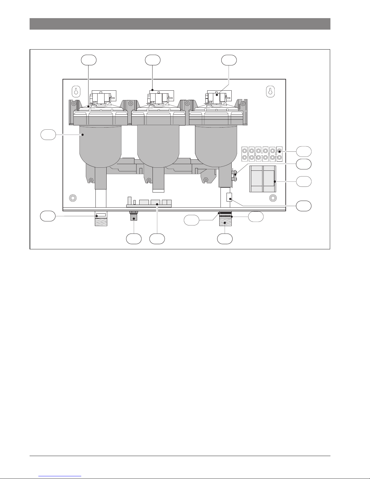
2.5 Components Diagram
Fig. 1
[A] Heating module
[B] Heating element assembly
[C] Heating module PCB
[D] Hot water outlet
[E] Cold water inlet
[F] Temperature adjustment knob
[G] Flow transducer
[H] Terminal block (CANADA ONLY)
[I] 6 way terminal block
[J] Temperature sensor
[K] Control PCB
[L] Double pole thermal cut-out
[M] Inlet water filter
[N] Flow regulator
6720647022-01.1V
A
D
F K
G
E
L
J
C
B
H
I
N
M
6 720 647 022 (2013/04)Tronic 5000C
Information about the heater | 5
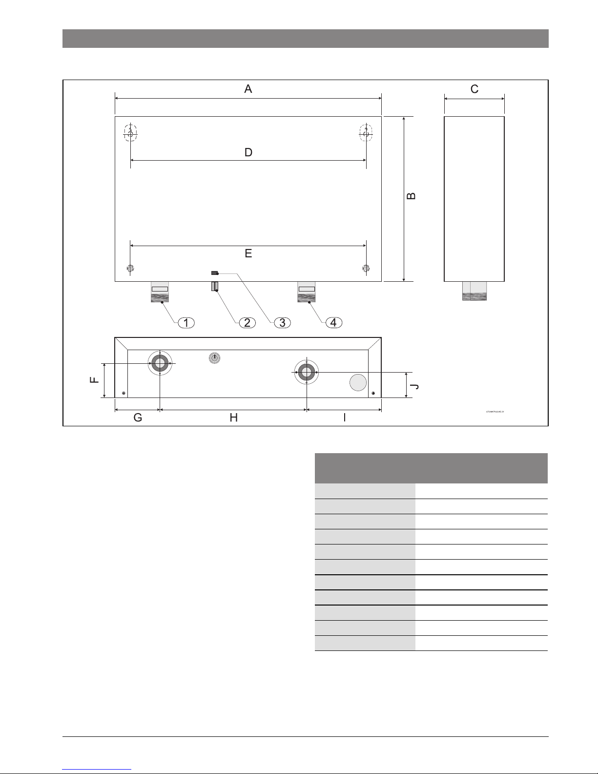
2.6 Dimensions
Fig. 2
[1] Outlet ¾ " NPT (hot water)
[2] Temperature knob
[3] LED
[4] Inlet ¾ " NPT (cold water)
Dimensions
(inches) WH36
A (Width) 20 "
B (Height) 12½ "
C (Depth) 4½ "
D 17 5/
8
"
E 17 5/
8
"
F2
5
/
8
"
G 3 3/
8
"
H 11 1/
8
"
I5
5
/
8
"
J1
7
/
8
"
Water connections ¾ "
Table 4 Dimensions
6 720 647 022 (2013/04) Tronic 5000C
6 | Information about the heater
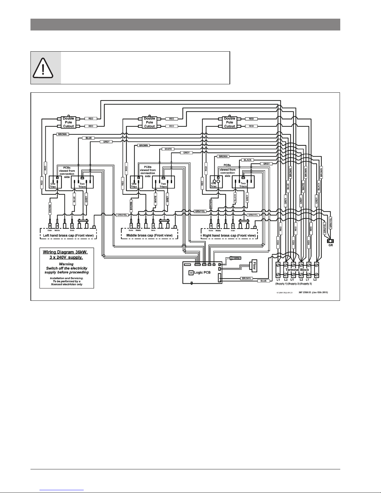
2.7 Wiring diagram
Fig. 3 Internal wiring schematic for single phase WH36 unit.
2.8 Description of the heater
How the Tronic 5000C Pro works;
• The Tronic 5000C Pro heats water continuously as it flows
through the heater modules.
• The electronic control PCB monitors the flow rate and the
incoming water temperature and then switches on the
required number of heater elements to reach the
temperature set by the temperature adjustment dial.
• As the flow rate or the incoming water temperature
changes, the electronic control adjusts the number of
heater elements used so that the outlet temperature is
maintained.
• The outlet water temperature can change slightly as the
flow rate changes due to the steps in power as different
heater elements are switched on and off.
• The outlet water temperature can also vary if the maximum
flow rate is exceeded (see Fig. 8) or if the supply voltage
changes.
• Each heater module is protected by an electro-mechanical
thermal cut-out. If the temperature of any of the heater
modules gets too high, then the cut-out will trip and cut the
power to that heater module. If the cut-out trips, it must be
reset while the circuit breakers are off. If you are not
comfortable or qualified to perform this task, consult the
original installer or a licensed electrician. This cut-out will
only trip in exceptional circumstances.
• Depending on the region of the country, the temperature of
the water supply can vary between 40°F in winter to 80°F in
summer, with an average of 55°F. The output temperature
at maximum flow of the heater is dependent on inlet water
temperature.
DANGER: Risk of electric shock!
▶ Always switch off the electricity supply to the unit before any
intervention in the heater.

6 720 647 022 (2013/04)Tronic 5000C
Regulations | 7
2.9 Technical specifications
3 Regulations
Any local by-laws and regulations pertaining to installation and
use of electric water heating appliances must be observed.
Please refer to the laws that should be attended in your
country.
• The electrical installation must conform to current National
Electrical Codes.
• As per the Canadian Electrical Code, C22.1-02 Section 26744, an auxiliary terminal block must be fitted to the unit
before connecting to the electrical supply.
• A green terminal (or wire connection marked “G”, “GR”,
“GROUND” or “GROUNDING”) is provided within the
control box. Aditional Canadian safety instructions, to
reduce the risk of electrical shock, connect this terminal or
connector to the grounding terminal of the electrical
service of supply panel with a continuous copper wire in
accordance with the Canadian Electrical Code, Part I.
• In Canada, this product shall be protected by a Class A
ground fault circuit interrupter.
• In the Commonwealth of Massachusetts a licensed
plumber or electrician must perform the installation.
(Approval number: P1-09-25).
• In the Commonwealth of Massachusetts a pressure relief
valve shall be installed on the cold water side by a licensed
plumber. (MGL 142 Section 19, Approval number P1-09-
25).
• The unit must be wired by a qualified electrician, in
accordance with the current version of the National
Electrical Code US) or Canadian Electric Code (Canada).
• When the heater is not within sight of the electrical circuit
breakers, a circuit breaker lockout or additional local
means of disconnection for all non-grounded conductors
must be provided that is within sight of the appliance. (Ref
NEC 422.31.).
• The power cable size and the installation must be in
accordance with the Canadian Electrical Code, C22.1-02.
Technical characteristics Units WH36
Voltage supply V 3 X 240 (Canada 240VAC)
Amperage A 3 x 60A (Canada 180A)
Maximum output kW 36.0kW
Temperature control range 95 °F to 131 °F
Minimum water pressure psi 15psi
Maximum water pressure psi 150psi
Minimum flow rate gal/min 0.8 US gal / min
Maximum flow rate (refer to Fig. 8)
Weight (without water) lbs 26.5 lbs
The unit will work at lower supply voltages but the following changes will apply:
Maximum output 30.2kW at 220V
27.0kW at 208V
Temperature control range 87 °F to 116 °F at 220V
82 °F to 108 °F at 208V
Maximum power
(refer to Fig. 8)
84% of maximum at 220V
75% of maximum at 208V
Table 5
WARNING:
California Proposition 65 lists chemical
substances known to the state to cause
cancer, birth defects, death, serious illness
or other reproductive harm. This product
may contain such substances, be their
origin from fuel combustion (gas, oil) or
components of the product itself.
6 720 647 022 (2013/04) Tronic 5000C
8 | Installation
4 Installation
4.1 Important information
Please follow these instructions. Failure to follow instructions
may result in:
• Damage or injury.
• Improper installation/operation.
• Loss of warranty.
4.2 Selection of place of installation
• If being used in a public place, locate the heater out of easy
reach to discourage vandalism.
• Mount the unit onto a flat section of wall, well away from
any potential splashes of water or spray and away from
areas where direct moist or wet contact could occur.
• Install the heater in a place that provides easy access for
any service or maintenance.
4.2.1 Freeze prevention
Introduction
Please note that the water heater must not be installed in a
location where it may be exposed to freezing temperatures. If
the heater must be left in a space that is likely to experience
freezing temperatures, all water must be drained from the
heater. See Section 6.
Freeze damage is not covered under the warranty.
DANGER: Risk of electric shock!
▶ For safety reasons, disconnect the
power supply to the heater before any
service or testing is performed.
WARNING:
▶ This heater must be electrically
grounded in accordance with the most
recent edition of the National Electrical
Code. NFPA 70. In Canada, all electrical
wiring to the heater must be in
accordance with local codes and the
Canadian Electrical Code, CSA C22.1
Part 1.
DANGER:
▶ The installation must only be performed
by a qualified person in accordance with
these instructions.
▶ Bosch Thermotechnology Corp. is not
responsible for improperly installed
appliances.
WARNING:
▶ The heater must only be mounted in a
vertical position with the water fittings
located at the bottom of the heater.
Under no circumstances should the
heater be mounted differently.
WARNING:
▶ The appliance should be located in an
area where leakage of the heater or
connections will not result in damage to
the area adjacent to the appliance or to
lower floors of the structure.
WARNING: Risk of freezing!
▶ Do not install the water heater in an area
where there is a chance of freezing.
Damage to the water heater as a result
of freezing will not be covered under
warranty.
WARNING:
▶ ELECTRICITY IS EXTREMELY
DANGEROUS. TAKE EXTRA
PRECAUTIONS AND ENSURE ALL
CIRCUIT BREAKERS ARE OFF BEFORE
PERFORMING ANY WORK TO THE
HEATER.
WARNING:
▶ Indoor installation only, where it will
NOT be exposed to freezing.
Use of chemical agents such as anti-freeze
are not allowed as they may cause damage to
the water heater’s internal components.

6 720 647 022 (2013/04)Tronic 5000C
Installation | 9
4.2.2 Recomended minimum clearances for servicing
Should it be necessary to service the Tronic 5000C Pro,
observe the following clearances. These are not required
clearances, but would facilitate any service work.
Fig. 4 Recommended minimum clearances
4.3 Mounting the water heater
▶ Undo the retaining screws on the front cover and take the
cover off the heater. Hold the back plate in position against
the wall and mark the four mounting holes.
▶ Drill the holes and secure the heater using the four wood
screws supplied.
Fig. 5 Vertical mounting position
WH36
Top (A) 12”
Sides 0”
Bottom (B) 6”
Front (C) 12”
Table 6 Recommended minimum clearances
WARNING:
▶ The heater must only be installed in the
orientation shown in Fig. 5 i.e., mounted
in a vertical position with the water
fittings located at the bottom of the
heater. Under no circumstances
should the heater be mounted
differently.

6 720 647 022 (2013/04) Tronic 5000C
10 | Installation
4.4 Water connections
▶ The heater must be connected directly to the main cold
water supply and not to pre-heated water. (The inlet
water temperature must not be greater than 86 °F).
▶ The heater must be installed with shutoff valves on both the
inlet and outlet connections.
▶ It is recommended that you use ¾ inch or ½ inch copper or
high-pressure flex connections.
▶ Do not use plastic piping within 3 feet on either side of
heater.
▶ Use Teflon tape for sealing pipe threads. Do NOT use pipe
dope.
▶ Remember to keep the hot water pipe runs as short as
possible.
After the heater has been plumbed, and before you wire it,
flush it with water to remove any debris or loose particles.
Heater must be full of water and air purged before power is
turned on. Failure to do so may result in damage to the
product that is not covered by warranty.
▶ After flushing and filling the heater with water, (with power
off) disconnect the inlet connection and inspect the filter
screen for any debris that may have been flushed through
the system.
▶ Check the pressure of the main water supply. To operate
correctly, the heater needs the running pressures
mentioned in 5.
4.4.1 Water quality
Water quality can have an impact on appliance longevity and
may not be covered under the manufacturer's warranty.
▶ For water analysis data call your local water department, or
if on a well, have well water analyzed periodically.
If water quality exceeds one or more of the values specified
below, Bosch recommends consulting a local water
treatment professional for water softening/conditioning
options.
4.5 Electrical connections
WARNING:
▶ Do not install a non-return check valve
within 10 feet of the inlet.
WARNING:
▶ Do not apply heat or solder to
connections or pipe if they are already
connected to the unit.
NOTICE: Disclaimer
▶ In the Commonwealth of Massachusetts
a pressure relief valve shall be installed
on the cold water side by a licensed
plumber. (MGL 142 Section 19,
Approval number P1-09-25).
The inlet and outlet connections are clearly
marked on the heater. They each have a
¾ inch NPT connector.
Description Max. Levels
pH pH 6.5 - 8.5
TDS (total Dissolved Solids) mg/l or ppm 500
Total hardness mg/l or ppm 100
(6 grains)
Aluminum mg/l or ppm 2.0
Chlorides mg/l or ppm 250
Copper mg/l or ppm 1.0
Iron mg/l or ppm 0.3
Manganese mg/l or ppm 0.05
Zinc mg/l or ppm 5.0
Table 7
WARNING:
▶ The unit must be wired by a qualified
electrician, in accordance with the
current version of the National Electrical
Code US) or Canadian Electric Code
(Canada).
When the heater is not within sight of the
electrical circuit breakers, a circuit breaker
lockout or additional local means of
disconnection for all non-grounded
conductors must be provided that is within
sight of the appliance. (Ref NEC 422.31.).
6 720 647 022 (2013/04)Tronic 5000C
Installation | 11
US wiring
• The minimum recommended wire size is 6 AWG. (The
terminal block will accept cables up to 6 AWG size).
• The cable entry is via the 1¼ inch cable entry hole on the
bottom right hand edge of the back plate.
• Strip back the insulation on the power wires about ½ inch.
Connect the live wires to the terminals marked “L1” and
“L2.” There are three pairs of live wires in the WH36. (See
Fig. 6, page 11).
• Any insulation on the ground wires should be stripped back
about ¾ inch. The ground leads must be connected. Loose
connections can cause wires to heat up.
• Make sure the terminal block screws are tightened
securely. Loose connections can cause wires to heat up.
• Make sure that the ground wires are wrapped around its
terminal stud and into the saddle washer. The nut should be
tightened securely.
• Attach the front cover and tighten the retaining screws.
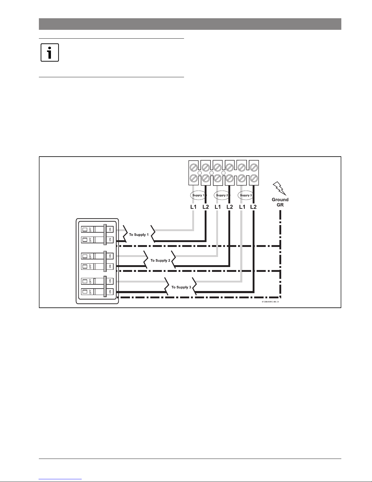
The WH36 requires three independent 240V AC circuits
protected by three separate and independent double pole
breakers (as shown) rated at least 54A each.
Fig. 6 WH36 terminal block connection (for the U.S.A.)
As per the Canadian Electrical Code, C22.102 Section 26-744, an auxiliary terminal
block must be fitted to the heater before
connecting to the electrical supply.
6 720 647 022 (2013/04) Tronic 5000C
12 | Installation
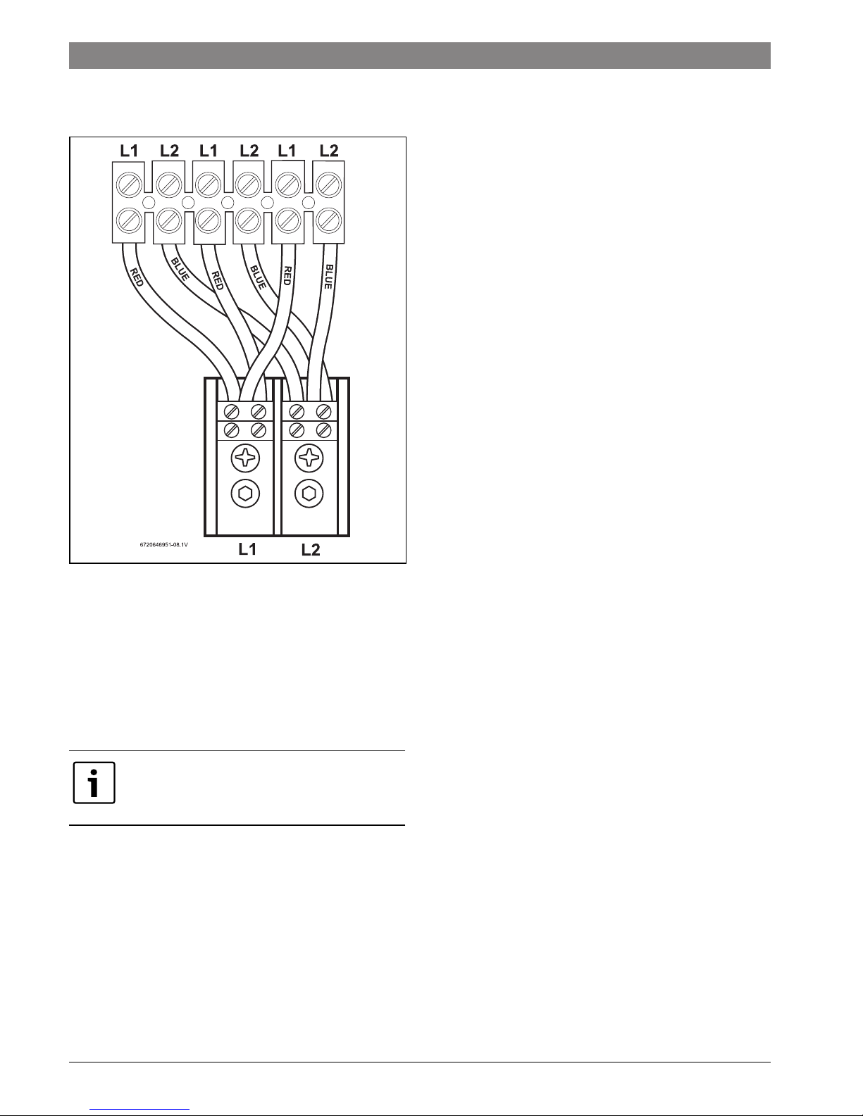
Canadian Wiring - auxiliary terminal block and connections
Fitting the auxiliary terminal block (see diagram below).
Fig. 7 For Canada only (Not for U.S.A.)
▶ Connect the red wires from the left hand terminal of the
new block to the L1 terminals in the unit.
▶ Connect the blue wires from the right hand terminal of the
new block to the L2 terminals in the unit.
▶ Push and click the auxiliary terminal block onto the
louvered rail in the backplate.
Connecting the supply cable - Canada only - not for the USA.
• The power cable size and the installation must be in
accordance with the Canadian Electrical Code, C22.1-02.
• The incoming hole diameter on auxiliary terminal block can
accept up to 1/0 AWG size cables.
• The cable entry is via the 1 ¼ inch cable entry hole on the
bottom right hand edge of the back plate.
• Strip back the insulation on the power wires about ½ inch.
Connect the ungrounded conductors to the terminals “L1”
and “L2” on the auxiliary terminal block.
• Any insulation on the ground wire should be stripped back
about ¾ inch. The ground lead must be connected to the
pillar terminal marked “GR.”
• Make sure the terminal block screws are tightened
securely. Loose connections can cause wires to heat up.
• Make sure that the ground wire is wrapped around its
terminal stud and into the saddle washer. The nut should be
tightened securely.
• Attach the front cover and tighten the retaining screws.
The WH36 requires a 180A 240V AC
single phase supply protected by a double
pole circuit breaker rated for at least 162A.
6 720 647 022 (2013/04)Tronic 5000C
Installation | 13
4.6 Starting up
4.6.1 Checking for leaks and purging air
▶ Verify all circuit breakers supplying power to the water
heater are turned off.
▶ Open all hot water taps supplied by the water heater and
inspect all water connections for leaks.
▶ With all hot water taps still open, inspect each tap to ensure
all air in the lines has been purged out.
▶ With the air purged and taps still flowing, turn on all circuit
breakers supplying the water heater.
▶ Close all hot water taps and proceed to the next section.
4.6.2 Adjusting the temperature dial
▶ The temperature adjustment is made using the dial on the
bottom edge of the unit. The adjustment is between
approximately 95 °F and 131 °F. Turning the dial clockwise
increases the temperature setting as indicated by the
marking on the unit.
4.6.3 Adjusting the flow
▶ Open fully both inlet and outlet shut-off valves at the
heater, then:
▶ Turn on fully the highest flowing hot water faucet (e.g.,
bathtub) served by the water heater.
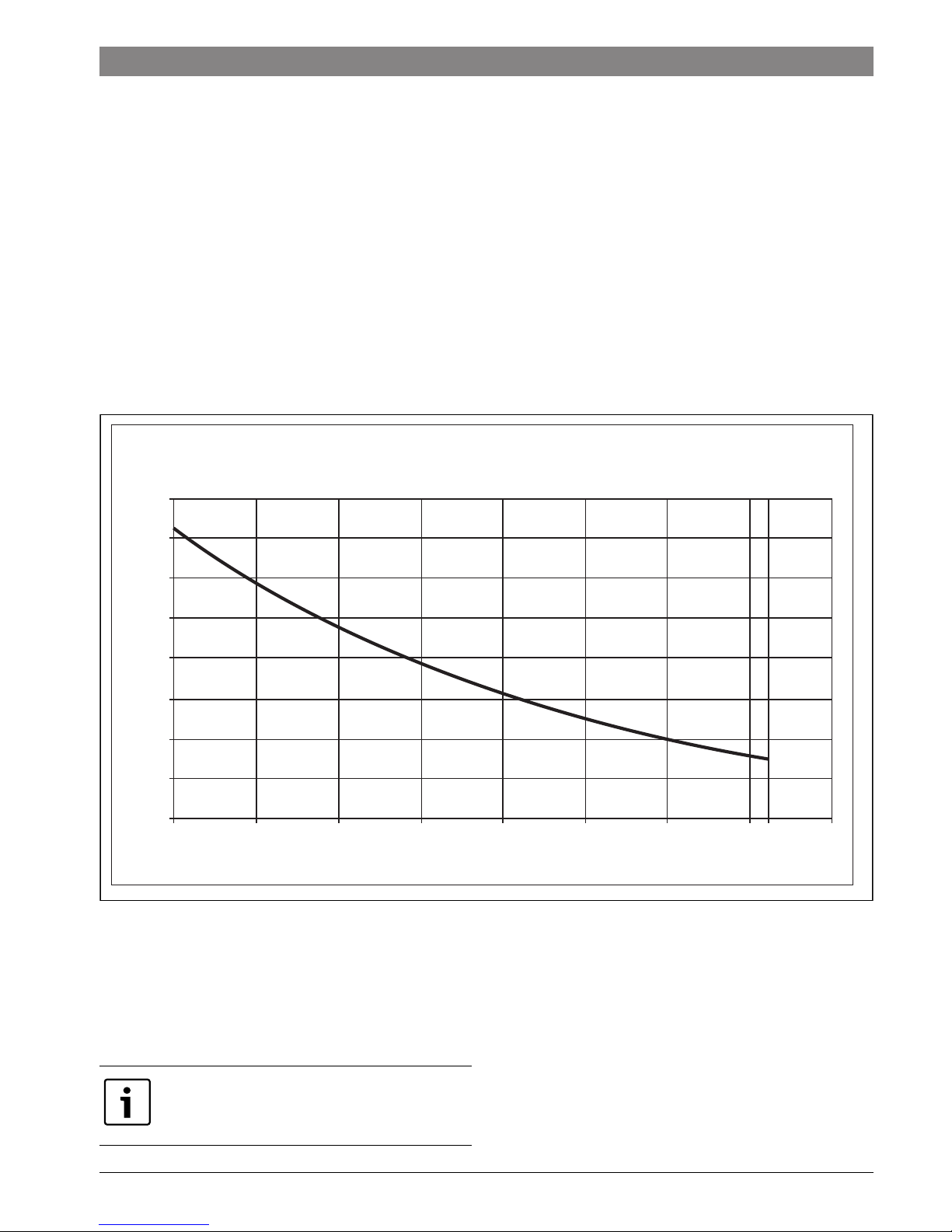
▶ Adjust the outlet shut-off valve until the water flow rate
from the hot faucet corresponds to the value given in Fig. 8
below.
Fig. 8
These figures are based on an inlet water temperature of 55 °F
and a supply voltage of 240 volts. If the inlet water temperature
is lower than 55 °F, or if the supply voltage is less than 240
volts, then the outlet temperature will be lower than what is
shown in Fig. 8. If a higher outlet water temperature is desired,
then reduce the flow rate and/or supply the unit with 240 volts.
95 100 105 110 130115 120 125 135
2.50
Outlet temperature (ºF)
Max Flow Rate (US gal/min)
Outlet temperature vs Maximum flow rate setting
(based on incoming water temperature of 55ºF)
6720647022-03.1V
3.00
3.50
4.00
4.50
5.00
5.50
6.00
6.50
131
Before leaving the site, the installer should
demonstrate the unit to the user and give
them this guide.
6 720 647 022 (2013/04) Tronic 5000C
14 | Operation instructions
5 Operation instructions
5.1 Before using the water heater
▶ Check that the power is switched on at the circuit breaker
panel.
▶ Turn on the hot water faucet FULLY.
• There are internal safety thermal cut-outs which will trip if
the unit overheats. If the cut-out trips, it must be reset while
the circuit breakers are off. If you are not comfortable or
qualified to perform this task, consult the original installer
or a licensed electrician.
• If the unit has been used recently, run the water through for
a few seconds to let the temperature cool down. You may
initially get a short burst of very hot water that was in the
plumbing lines from previous use.
• If a second outlet connected to the unit is also turned on,
the hot water will be shared between the two.
6 Maintenance
Draining the heater
Due to the shape of the heat exchangers and connecting pipe,
it is extremely difficult to get all of the water out of the heater.
Follow the procedure below to best minimize the chance of
freezing:
▶ Disconnect electric supply.
▶ Disconnect cold and hot water pipes from fittings on
bottom of heater. Allow water to drain out (have a catch
basin ready).
▶ After allowing all water to drain out, the heater should be
blown out with low pressure compressed air to remove as
much water as possible from water heater modules. Bursts
of air work better than continuous flow.
Remember, these suggestions are only made to help minimize
the potential for freeze damage and are not to be construed as
the guaranteed method for dealing with freeze possibilities.
Check inlet water filter screen once a year
▶ Check that the power is switched off at the circuit breaker
panel.
▶ Shut off the installer supplied cold water isolation valve to
the heater. If one is not installed, install before proceeding.
▶ Open nearest hot water tap to relieve pressure in the
plumbing lines.
▶ Position a bucket under the cold water inlet connection of
the heater to catch any water that may drain.
▶ Disconnect the cold water plumbing connection from the
inlet (bottom right of heater) to access filter screen.
▶ Remove filter, clean with water and inspect for damage. If
the filter is at all damaged, it should be replaced.
▶ Replace the filter into the inlet housing
▶ DO NOT leave the filter out.
▶ DO NOT remove the flow regulator (located behind the
filter).
▶ DO NOT clear the filter by back flushing.
▶ Before switching power back on, open all hot water taps
and inspect each tap to ensure all air in the lines has been
purged out. With the air purged and taps still flowing, turn
on all circuit breakers supplying the water heater.
▶ Close all hot water taps and proceed for normal operation.
WARNING:
▶ Do not use the unit if you think it may be
frozen, as this could result in serious
damage to the unit. Wait until you are
sure that it has completely thawed out
before you switch it on.
The hot water temperature can be changed
by adjusting the temperature dial on the
bottom surface of the unit. (The dial adjusts
the temperature typically between 95°F and
131°F. The factory sets the temperature dial
at the lowest position).
6 720 647 022 (2013/04)Tronic 5000C
Maintenance | 15
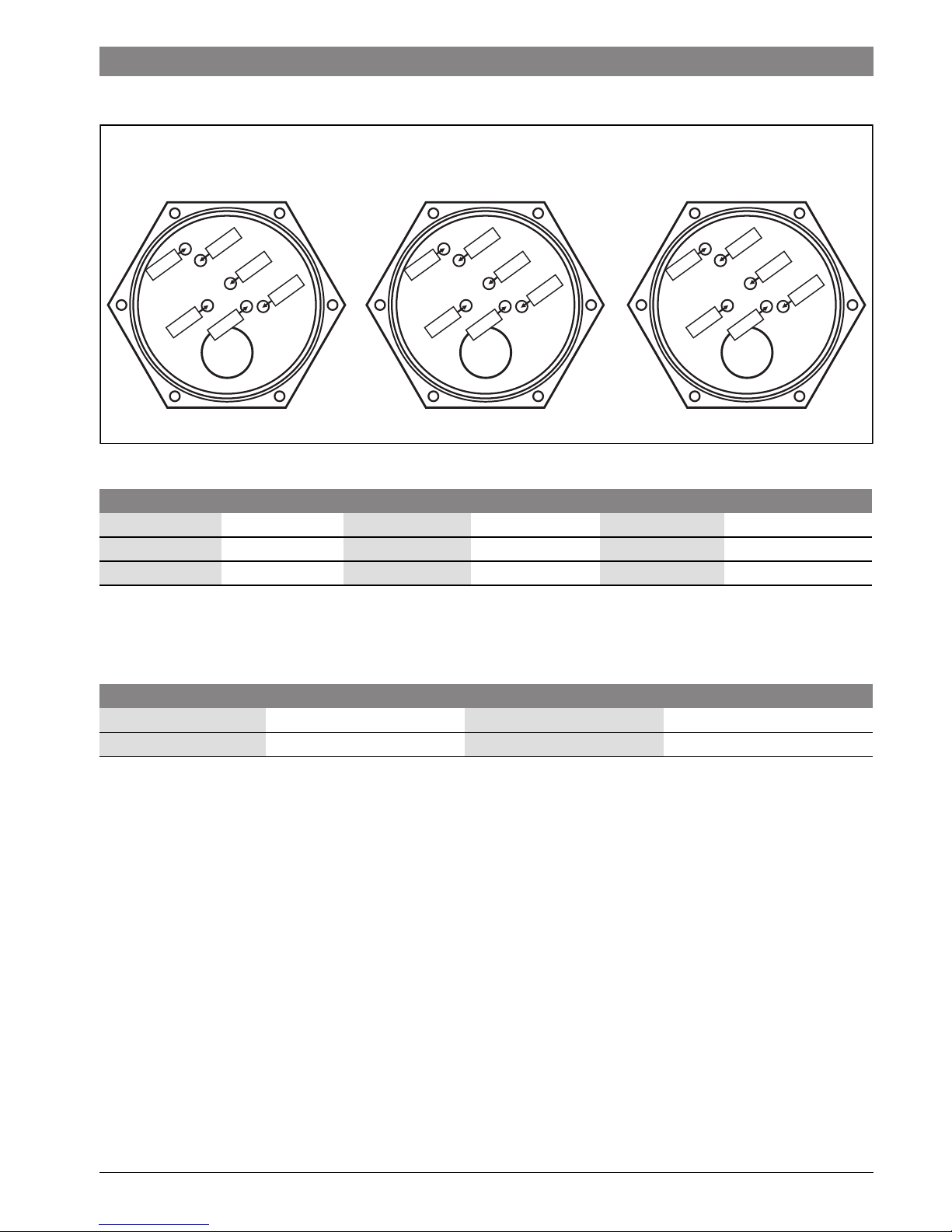
Using an ohmmeter to check for premature element failure
Fig. 9 Heating elements
The WH36 models are rated for 240V and will also operate at
220V or 208V with reduced output. The output will vary in
accordance with the ratios, mentioned in table 10.
Outer
Middle
Outer
Middle
Inner
Inner
Rear of Heater
Rear of Heater
Front of Heater
Front of Heater
Outer
Middle
Outer
Middle
Inner
Inner
Rear of Heater
Rear of Heater
Front of Heater
Front of Heater
Center Module Top View
Center Module Top View
RIGHT MODULE Top View
RIGHT MODULE Top View
6720647022-02.1V
Outer
Middle
Outer
Middle
Inner
Inner
Rear of Heater
Rear of Heater
Front of Heater
Front of Heater
LEFT MODULE Top View
LEFT MODULE Top View
Meter probes Ohm Readings Meter probes Ohm Readings Meter probes Ohm Readings
Outer to Outer 10.5 ± 0.8 Ohms Outer to Outer 11.4 ± 0.9 Ohms Outer to Outer 9.9 ± 0.8 Ohms
Middle to Middle 14.3 ± 0.9 Ohms Middle to Middle 12.1 ± 0.9 Ohms Middle to Middle 13.1 ± 0.9 Ohms
Inner to Inner 16.0 ± 1.2 Ohms Inner to Inner 17.8 ± 1.3 Ohms Inner to Inner 20.0 ± 1.4 Ohms
Table 8
Ratios
Volts 208V 220V 240V
Output Ratio 0.75 0.84 1
Table 9
6 720 647 022 (2013/04) Tronic 5000C
16 | Troubleshooting
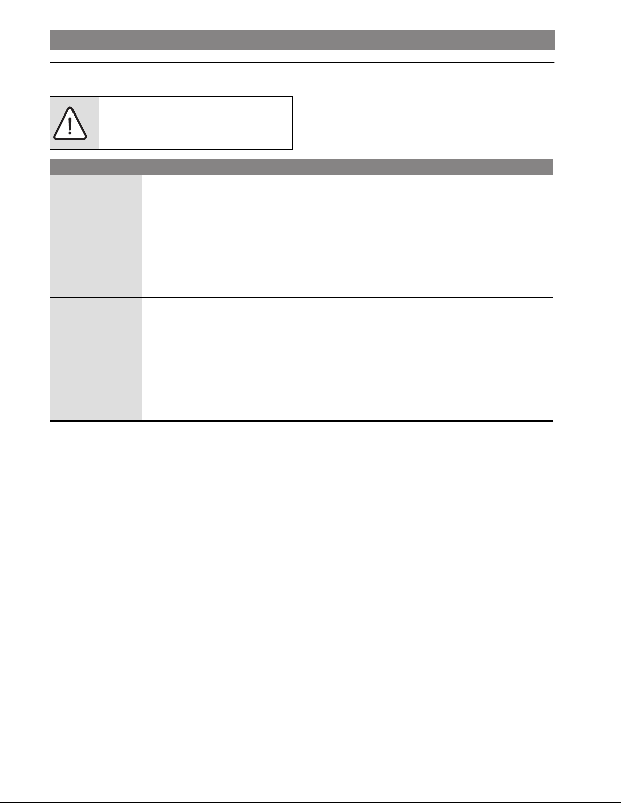
7 Troubleshooting
Important: If you are unable to perform the tasks listed below,
or need additional assistance please contact your original
installer/licensed electrician.
DANGER: Risk of electric shock!
▶ Always switch off the electricity supply
to the unit before you remove the cover.
Cold water only – Neon light off
Flow rate is too low Verify the flow rate out of fixture is at or above the minimum activation rate required for the unit to
activate. (Activation rate: WH36 = 0.8 GPM).
Plumbing crossover To test for a plumbing crossover, turn off power supply to the heater. Close installer supplied cold water
shut off valve (if none installed, install before proceeding). Open all hot water taps supplied by the
heater. Wait 5 minutes and check all taps. Any water running is a sign of a plumbing crossover. Consult a
local plumber or service person for help in correcting a plumbing crossover. To return the heater to
service, reinstall cover, open the inlet water supply to the heater and open all hot water taps. Let all taps
run until there is no air coming out of the fixtures. Shut off all hot water taps. Turn power supply on to the
heater. Return heater to service. (This procedure will prevent the heating elements from burning out).
The flow transducer is
not spinning
Turn off the power supply to the heater and remove the cover. Observe if the flow transducer "spins"
when the water is turned on. Please note the flow transducer spins at a high speed and can appear to be
stopped when actually spinning. It is recommended to observe the flow transducer without water
flowing, then turn on a hot water tap while observing the flow transducer. If the flow transducer is not
spinning, remove and flush flow transducer, noting the Do's and Dont's on page 14. See the technical
support section of www.bosch-climate.us for more detailed instruction on removing the flow transducer.
No electricity at the
heater or one of the
supplies has failed
Have a licensed electrician verify proper wiring and adequate voltage on the terminal block inside the
water heater. See the “Electrical connections” section on page 10 of this manual.
Table 10
6 720 647 022 (2013/04)Tronic 5000C
Troubleshooting | 17
Cold water only – Neon light on
One or more of the
heating module thermal
cut-outs has tripped
Shut off the power to the unit, remove the cover and locate thermal cutouts on the top of each
heating module. Try resetting each cutout by pushing the reset button located in the center of the
cutout. Determine and fix the cause of the overheating. Obstructions in the water path can restrict
the flow of water through the heater causing it to overheat. Verify the heater’s inlet filter screen and
all outlets served by the heater are clear of debris. Ensure the heater is not being fed preheated
water. This water heater is designed for a cold water feed only. If thermal cut out does not reset,
check for continuity through each cutout (Less than 0.5 Ohms). If any cutout reads more than 0.5
Ohms or open, then it may be defective and should be replaced.
The power supply voltage
has dropped
This is likely an issue with the incoming power supply. Have a qualified electrician measure voltage on
the water heater’s terminal block while operating at maximum flow and maximum temperature
setting. The WH36 models are rated for 240V and will also operate at 220V or 208V with reduced
output. The output will vary in accordance with the ratios, mentioned in table 9.
The inlet water
temperature is too cold
Verify the heater is sized appropriately for it’s geographic location. Turn temperature knob located on
the bottom of the water all the way clockwise for maximum temperature setting. Ensure flow rates are
within the heater’s specifications. Refer to Fig. 8 on page 13 of the manual. Use of an isolation valve
on the hot water outlet to control flow rate is recommended.
One of the power supplies
is not on
Have a licensed electrician verify adequate voltage on the terminal block inside the water heater.
Verify circuit breakers serving the heater are not tripped. See the “Electrical connections” section on
page 10 of this manual.
Premature element failure Shut off power to the unit and remove cover. Use an ohmmeter to verify correct resistance on each
element. If readings are different than listed specifications on page 15, contact Technical Support
800-798-8161 for further instruction.
Table 11
Water not hot enough - Neon light on
The water supply is
connected to the
outlet of the unit
Verify plumbing connections are correct (See Fig. 2). Reconnect the water supply to the inlet of the unit
(marked blue).
One or more of the
heating module
thermal cut-outs has
tripped
Turn off the power to the heater, remove the cover and locate thermal cutouts on the top of each heating
module. Try resetting each cutout by pushing the reset button located in the center of the cutout.
Determine and fix the cause of the overheating. Obstructions in the water path can restrict the flow of
water through the heater causing it to overheat. Verify the heater’s inlet filter screen and all outlets
served by the heater are clear of debris. Ensure the heater is not being fed preheated water. This water
heater is designed for a cold water supply only. If thermal cut out does not reset, check for continuity
through each cutout (less than 0.5 Ohms). If any cutout reads more than 0.5 Ohms or open, then it may
be defective and should be replaced.
Temperature dial is
turned too low
Turn the temperature dial located on the bottom of the water heater clockwise for hotter temperatures.
Refer to Fig. 8 for outlet temperature vs. flow rate variance.
Water flow is too high Adjust water flow to stay within the water heater’s specifications. See Fig. 8 of this manual.
Table 12
6 720 647 022 (2013/04) Tronic 5000C
18 | Troubleshooting
Water flow too low
There are restrictions
in the plumbing
Obstructions in the water path can restrict the flow of water through the heater. Verify the heater’s inlet
filter screen, faucet aerators, showerheads and whole house filters are clear of debris. Verify proper flow
on the outlet side of the heater with the hot water pipe disconnected. Maximum flow rates for each unit
are as follows. WH36 = 3.5gpm.
Water supply pressure
too low
Verify incoming water supply is at least 30psi. For people on well systems, the recommended pressure
range is 30-50psi.
Outlet shut-off valves
are set too low
Adjust installer supplied outlet valve as described below:
• Completely open both installer supplied inlet and outlet shut-off valves at the heater. (if none
installed, install before proceeding).
• Completely open hot water on the highest flowing hot water fixture served by the heater (i.e.
bathtub).
• Slowly close the outlet shut-off valve, slowing the water flow rate until the temperature at the hot
water faucet corresponds to the values given on Fig. 8 of the manual, or desired water temperature
is reached.
Table 13
Water Temperature too Hot
Temperature dial set too
high
Turn the temperature knob located on the bottom of the water heater counterclockwise for cooler
temperatures.
There are restrictions in
the plumbing
Obstructions in the water path can restrict the flow of water through the heater causing overheating.
Verify the heater’s inlet filter screen, faucet aerators, showerheads and whole house filters are clear
of debris. Verify proper flow on the outlet side of the heater with the hot water pipe disconnected.
Opening hot water isolation valve fully may be necessary. Maximum flow rates for each unit are as
follows, WH36 - 3.5gpm.
Inlet water temperature is
too warm
Verify the heater is being feed with cold water only. This water heater is not designed for preheated
water or recirculation applications. Increase flow rate where ever possible. Replacing low flow
showerheads and aerators with higher flowing (GPM) ones may be necessary.
Table 14
Water Temperature fluctuates
Cold mix, heater deactivates If inlet water temperature is over 70°F, water may be very hot out of the tap. This requires a lot
of cold water to be added in order to get a usable hot water temperature. The addition of too
much cold water will overpower hot water demand from the water heater. This slows the flow
within the water heater, decreasing it below the activation point, which shuts off the heater.
The end result is nothing but cold water coming out of the outlet. Increase the flow rate by
cleaning or replacing fixtures and lower the setting on the temperature adjustment knob.
Fluctuating water pressure If the water pressure in the home is erratic and the water flow is not consistent while a tap is
opened, then the temperature of hot water will fluctuate. The minimum water pressure for the
home should be 30psi or greater. For people on well systems the minimum pressure range is
30-50psi. The use of a pressure reducing/regulating valve is an effective way to maintain
constant water pressure to the water heater. Watts brand 25AUB- ¾” or N35B-¾” pressure
reducing/regulating valves or equivalent is suggested.
Changing flow rate.
Water supply connected to the
outlet of the unit.
Major changes in flow rate can adversely affect the output water temperature of the heater.
Increases from one major fixture running to multiple fixtures running at one time can cause the
temperature to fluctuate. Stay within the heater’s specifications. See Fig. 8.
Table 15
6 720 647 022 (2013/04)Tronic 5000C
Spare Parts | 19
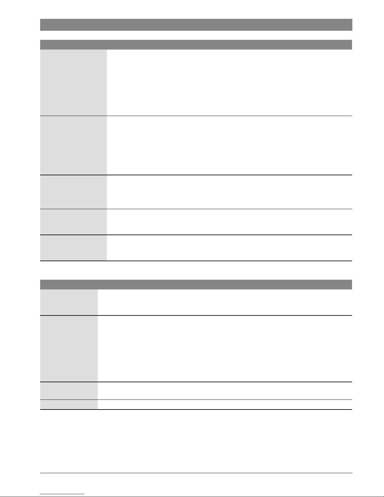
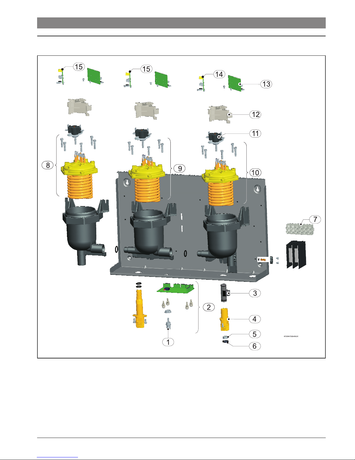
8 Spare Parts
Fig. 10

6 720 647 022 (2013/04) Tronic 5000C
20 | Spare Parts
Part number Spare part number Description
1 8-738-701-742-0 Temperature adjustment knob
2 8-738-701-744-0 Control PCB
3 8-738-701-743-0 Flow transducer
4 8-738-701-734-0 Brass Inlet
5 8-738-701-741-0 Flow Regulator
6 8-738-701-706-0 Water Filter
7 8-738-701-698-0 6 way term. block
8 8-738-701-745-0 Heater element assembly (left)
9 8-738-701-746-0 Heater element assembly (center)
10 8-738-701-747-0 Heater element assembly (right)
11 8-738-701-740-0 2 Pole Thermal Cutout
12 8-738-701-722-0 PCB Mount
13 8-738-701-723-0 Dual Channel PCB
14 8-738-701-748-0 Single Channel PCB Module 1
15 8-738-701-749-0 Single Channel PCB Module 2 and 3
Table 16
 Loading...