

Page 1
PRO tankless electric water heaters
6720646951-00.1V
TRONIC 5000C Pro
Models: WH17 / WH27
en Installation Manual and Operating Instructions 2
es Instrucciones de instalación y funcionamiento 28
fr Instructions d'installation et d'utilisation 54
IMPORTANT: This booklet should be given to the customer after installation and demonstration.
For Service & Installation contact:
BOSCH Thermotechnology Corp.
50 Wentworth Avenue, Londonderry
NH 03053
Phone: 800-798-8161
www.bosch-climate.us
6 720 646 951 (2011/09) US
Page 2
2 | Table of contents US
Table of contents
1 Explanation of symbols and safety information . 3
1.1 Explanation of symbols . . . . . . . . . . . . . . . . 3
1.2 Safety precautions . . . . . . . . . . . . . . . . . . . 3
2 General information . . . . . . . . . . . . . . . . . . . . . . . 5
2.1 Disclaimer . . . . . . . . . . . . . . . . . . . . . . . . . . 5
2.1.1 Approval number . . . . . . . . . . . . . . . . . . . . 5
2.2 Technical identification code . . . . . . . . . . . 5
2.3 Model name and number identification . . . 5
2.4 Package contents . . . . . . . . . . . . . . . . . . . . 5
2.5 Components Diagram . . . . . . . . . . . . . . . . . 6
2.6 Dimensions . . . . . . . . . . . . . . . . . . . . . . . . . 7
2.7 Wiring diagram . . . . . . . . . . . . . . . . . . . . . . 8
2.8 Function . . . . . . . . . . . . . . . . . . . . . . . . . . . 9
2.9 Technical specifications . . . . . . . . . . . . . . 10
3 Regulations . . . . . . . . . . . . . . . . . . . . . . . . . . . . . 11
4 Installation . . . . . . . . . . . . . . . . . . . . . . . . . . . . . 12
4.1 Important information . . . . . . . . . . . . . . . 12
4.2 Selection of place of installation . . . . . . . 12
4.2.1 Freeze prevention . . . . . . . . . . . . . . . . . . . 12
4.2.2 Recommended minimum clearances
for servicing . . . . . . . . . . . . . . . . . . . . . . . 13
4.3 Mounting the water heater . . . . . . . . . . . . 13
4.4 Water connections . . . . . . . . . . . . . . . . . . 14
4.4.1 Water quality . . . . . . . . . . . . . . . . . . . . . . . 14
4.5 Electrical connections . . . . . . . . . . . . . . . 14
4.6 Starting up . . . . . . . . . . . . . . . . . . . . . . . . 18
4.6.1 Checking for leaks and purging air . . . . . . 18
4.6.2 Adjusting the temperature dial . . . . . . . . . 18
4.6.3 Adjusting the flow . . . . . . . . . . . . . . . . . . . 18
5 Operation instructions . . . . . . . . . . . . . . . . . . . . 19
5.1 Before using the water heater . . . . . . . . . 19
6 Maintenance . . . . . . . . . . . . . . . . . . . . . . . . . . . . 20
7 Troubleshooting . . . . . . . . . . . . . . . . . . . . . . . . . 22
8 Spare Parts . . . . . . . . . . . . . . . . . . . . . . . . . . . . . 26
Copyright6 720 646 951 (2011/09)
Page 3
Explanation of symbols and safety information | 3US
1 Explanation of symbols and safety information
1.1 Explanation of symbols
Warnings
Warnings are indicated in the text by a
warning triangle and a gray background.
In case of danger due to electric shock, the
exclamation point on the warning triangle is
replaced with a lightning symbol.
Signal words at the beginning of a warning are used to
indicate the type and seriousness of the ensuing risk if
measures for minimizing damage are not taken.
• NOTE indicates possible minor to medium personal
injury.
• CAUTION indicates possible minor to medium
personal injury.
• WARNING indicates possible severe personal injury.
• DANGER indicates that severe personal injury may
occur.
Important information
Important information that presents no risk
to people or property is indicated with this
symbol. It is separated by horizontal lines
above and below the text.
Additional symbols
Symbol Meaning
B a step in an action sequence
1.2 Safety precautions
When using this electrical equipment, basic safety
precautions should always be followed, including the
following:
B READ AND FOLLOW ALL INSTRUCTIONS.
B This appliance must be grounded.
B Disconnect this product from the electrical supply
before cleaning, servicing or removing the cover.
B To reduce the risk of injury, close supervision is
necessary when the product is used near children or
elderly persons.
B Warning: Mount the unit onto a flat section of wall,
well away from any potential splashes of water or
spray and away from areas where direct moist or wet
contact could occur.
B Warning: Indoor installation only, where it will NOT be
exposed to freezing.
B Warning: Do not install a check valve or any other type
of back flow preventer within ten feet of the cold
water inlet.
B The electrical installation must conform to current
National Electrical Codes.
B Warning: Do not switch the heater on if you suspect
that it may be frozen. Wait until you are sure that it
has completely thawed out.
B The Tronic 5000C Pro is designed to heat potable cold
water for domestic purposes. The heater is not
designed to accept inlet water temperatures above
86° F. Contact Bosch Thermotechnology Corp. before
specifying or installing the appliance in any other
application.
→ a reference to a related part in the
document or to other related documents
• a list entry
– a list entry (second level)
Tab. 1
6 720 646 951 (2011/09)Copyright
Page 4

4 | Explanation of symbols and safety information US
B Additional Canadian safety instructions:
– As per the Canadian Electrical Code, C22.1-02
Section 26-744, an auxiliary terminal block must be
fitted to the unit before connecting to the electrical
supply (Kit Part N° “AE Canada Kit”).
(See Page 17).
– A green terminal (or a wire connector marked “G,”
“GR,” “GROUND” or “GROUNDING”) is provided
within the control. To reduce the risk of electrical
shock, connect this terminal or connector to the
grounding terminal of the electrical service of
supply panel with a continuous copper wire in
accordance with the Canadian Electrical Code,
Part I.
– This product shall be protected by a Class A ground
fault circuit interrupter.
B Keep this manual in a safe place once the unit has
been installed as it may be needed for future
reference.
Copyright6 720 646 951 (2011/09)
Page 5
2 General information
2.1 Disclaimer
General information | 5US
2.1.1
Commonwealth of Massachusetts
In the Commonwealth of Massachusetts a licensed
plumber or electrician must perform the installation.
(Approval number: P1-09-25).
Approval number
2.2 Technical identification code
EI 17 E/M W I H B
EI 27 E/M W I H B
Tab. 2
EI Electronic Instantaneous
17 Maximum output (kW)
E/M Electronic / mechanical temperature control
W Wall hung
I Indoor
H Horizontal installation
B Water connections
2.3 Model name and number
identification
Model Name Model Number
WH17 EI 17 E/M W I H B
WH27 EI 27 E/M W I H B
Tab. 3
2.4 Package contents
• Tankless electric water heater.
• 4 screws and gasket.
6 720 646 951 (2011/09)Copyright
Page 6
6 | General information US
6720646951-14.1V
G
E
L
J
H
I
N
M
F K
A
D
C
B
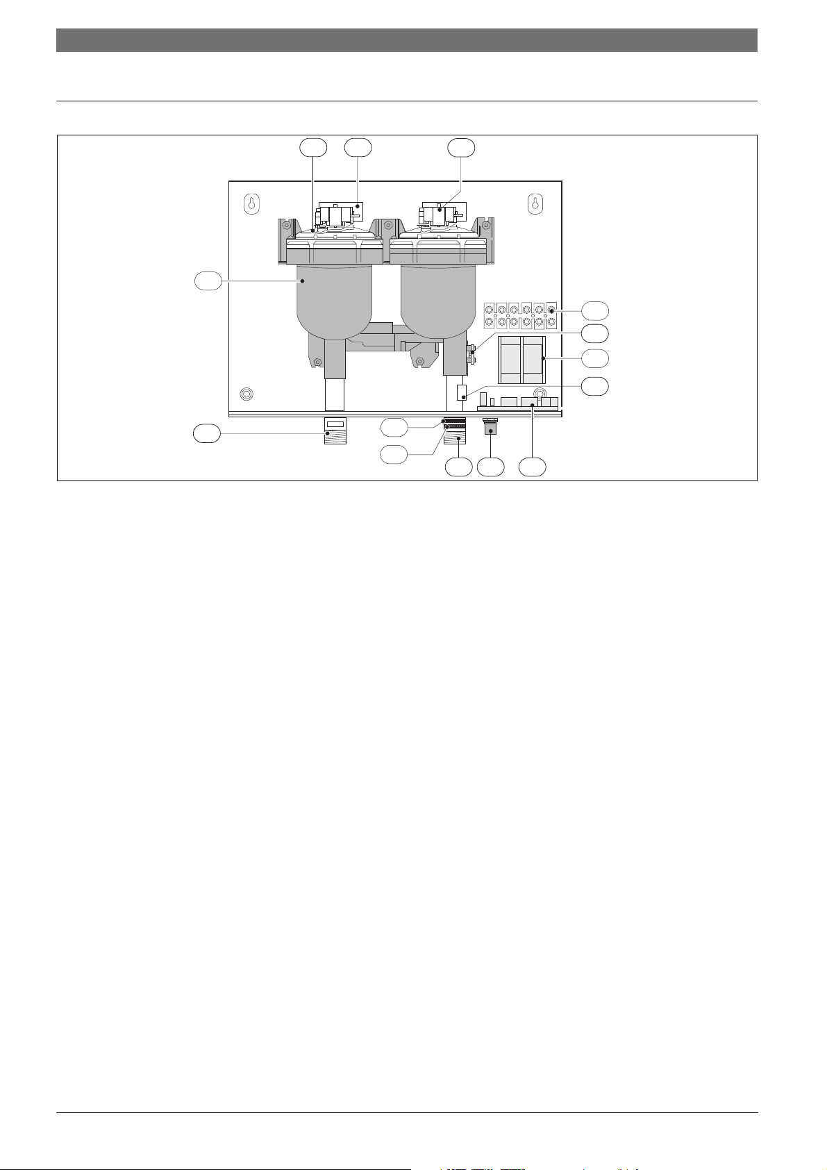
2.5 Components Diagram
Fig. 1
A Heating module
B Heating element assembly
C Heating module PCB
D Hot water outlet
E Cold water inlet
F Temperature adjustment knob
G Flow transducer
H Terminal block (CANADA ONLY)
I 6 way terminal block
J Temperature sensor
K Control PCB
L Double pole thermal cut-out
M Inlet water filter
N Flow regulator
Copyright6 720 646 951 (2011/09)
Page 7

2.6 Dimensions
General information | 7US
Fig. 2
1 Outlet ¾" NPT (hot water)
2 Inlet ¾" NPT (cold water)
3 Temperature knob
4 LED
Dimensions
(inches) WH17 / WH27
A (Width) 15 ¼ "
B (Height) 12 ½ "
C (Depth) 4 ½ "
D 12 5/8"
E 12 5/8"
F 2 ½ "
G 3 ½ "
H 6
1
/8"
I 5 ¾ "
J 1 ¾ "
Water connections ¾ "
Tab. 4 Dimensions
6 720 646 951 (2011/09)Copyright
Page 8
8 | General information US
6720646951-02.1V
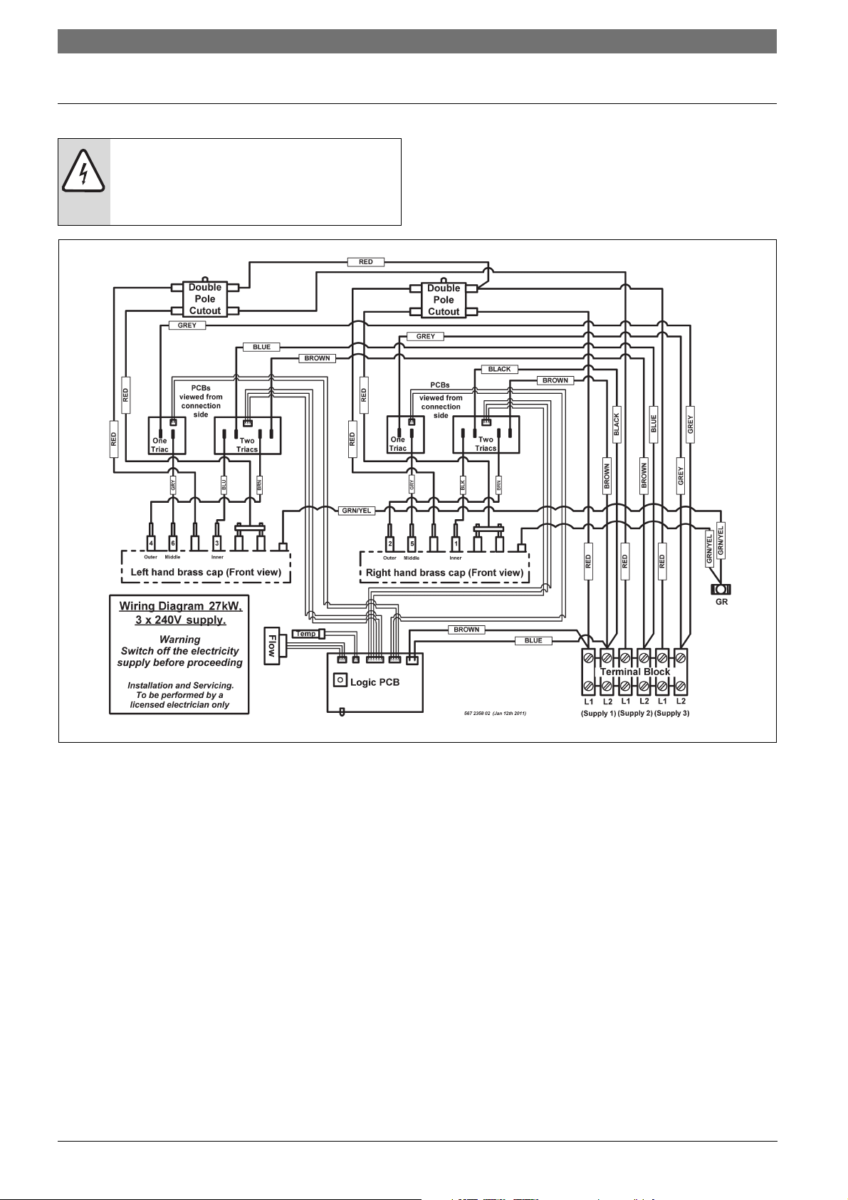
2.7 Wiring diagram
DANGER: Risk of electric shock!
B Always switch off the electricity supply to
the unit before any intervention in the
heater.
Fig. 3 Internal wiring schematic for single phase WH27 unit.
Copyright6 720 646 951 (2011/09)
Page 9
General information | 9US
6720646951-03.1V
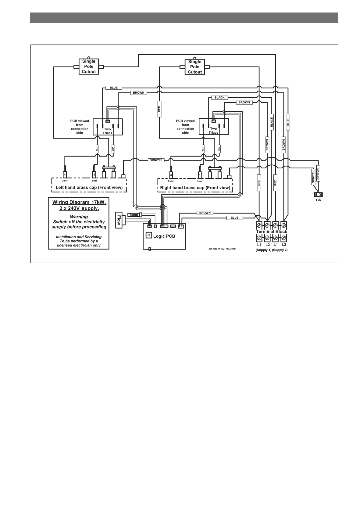
Fig. 4 Internal wiring schematic for single phase WH17 unit.
2.8 Function
How the water heater works:
• The Tronic 5000C Pro heats water continuously as it
flows through the heater modules.
• The electronic control PCB monitors the flow rate and
the incoming water temperature and then switches
on the required number of heater elements to reach
the temperature set by the temperature adjustment
dial.
• As the flow rate or the incoming water temperature
changes, the electronic control adjusts the number of
heater elements used so that the outlet temperature
is maintained.
• The outlet water temperature can change slightly as
the flow rate changes due to the steps in power as
different heater elements are switched on and off.
• The outlet water temperature can also vary if the
maximum flow rate is exceeded (see Fig. 11) or if the
supply voltage changes.
• Each heater module is protected by an electromechanical thermal cut-out. This cut-out will only trip
in exceptional circumstances.
Contact Technical Support 800-798-8161 for further
instruction.
• The WH17 unit is supplied from two independent
voltage supplies and the WH27 unit from three
independent voltage supplies. (In Canada the unit has
just one voltage supply).
• Depending on the region of the country, the
temperature of the water supply can vary between
40 °F in winter to 70 °F in summer, with an average of
55 °F. The output temperature and maximum flow of
the heater is dependent on inlet water temperature.
6 720 646 951 (2011/09)Copyright
Page 10
10 | General information US
2.9 Technical specifications
Technical characteristics Units WH17 WH27
Voltage supply V 2 X 240VAC (Canada 240VAC) 3 X 240VAC (Canada 240VAC)
Amperage A 2 X 40A (Canada 80A) 3 X 40A (Canada 120A)
Maximum output kW 17.25kW 26.85kW
Temperature control range 95 °F to 131 °F 95 °F to 131 °F
Minimum water pressure psi 15psi 15psi
Maximum water pressure psi 150psi 150psi
Minimum flow rate gal/min 0.6 US gal / min 0.8 US gal / min
Maximum flow rate (refer to Fig. 11) (refer to Fig. 11)
Weight (without water) lbs 20 lbs 22 lbs
The unit will work at lower supply voltages but the following changes will apply:
Maximum output 15kW at 220V 22.5kW at 220V
Maximum flow rate
(refer to Fig. 11)
Tab. 5
13kW at 208V 20kW at 208V
84% of maximum at 220V 84% of maximum at 220V
75% of maximum at 208V 75% of maximum at 208V
Copyright6 720 646 951 (2011/09)
Page 11
3 Regulations
Any local by-laws and regulations pertaining to
installation and use of electric water heating appliances
must be observed. Please refer to the laws that should
be attended in your country.
• The electrical installation must conform to current
National Electrical Codes.
• As per the Canadian Electrical Code, C22.1-02
Section 26-744, an auxiliary terminal block must be
fitted to the unit before connecting to the electrical
supply (Kit Part N° “AE Canada Kit”).
• A green terminal (or wire connection marked “G”,
“GR”, “GROUND” or “GROUNDING”) is provided
within the control box. Aditional Canadian safety
instructions, to reduce the risk of electrical shock,
connect this terminal or connector to the grounding
terminal of the electrical service of supply panel with
a continuous copper wire in accordance with the
Canadian Electrical Code, Part I.
• In Canada this product shall be protected by a Class
A ground fault circuit interrupter.
• In the Commonwealth of Massachusetts a licensed
plumber or electrician must perform the installation.
(Approval number: P1-09-25).
• In the Commonwealth of Massachusetts a pressure
relief valve shall be installed on the cold water side by
a licensed plumber. (MGL 142 Section 19, Approval
number P1-09-25).
• The unit must be wired by a qualified electrician, in
accordance with the current version of the National
Electrical Code US) or Canadian Electric Code
(Canada).
• When the heater is not within sight of the electrical
circuit breakers, a circuit breaker lockout or
additional local means of disconnection for all nongrounded conductors must be provided that is within
sight of the appliance. (Ref NEC 422.31.).
• The power cable size and the installation must be in
accordance with the Canadian Electrical Code, C22.1-
02.
Regulations | 11US
WARNING:
California Proposition 65 lists chemical
substances known to the state to cause
cancer, birth defects, death, serious illness
or other reproductive harm. This product
may contain such substances, be their
origin from fuel combustion (gas, oil) or
components of the product itself.
6 720 646 951 (2011/09)Copyright
Page 12
12 | Installation US
4 Installation
DANGER: Risk of electric shock!
B For safety reasons, disconnect the power
supply to the heater before any service or
testing is performed.
WARNING:
B This heater must be electrically grounded
in accordance with the most recent
edition of the National Electrical Code.
NFPA 70. In Canada, all electrical wiring
to the heater must be in accordance with
local codes and the Canadian Electrical
Code, CSA C22.1 Part 1.
4.1 Important information
DANGER:
B The installation must only be performed
by a qualified person in accordance with
these instructions.
B Bosch Thermotechnology Corp. is not
responsible for improperly installed
appliances.
WARNING:
B The heater must only be mounted in a
vertical position with the water fittings
located at the bottom of the heater.
Under no circumstances should the
heater be mounted differently.
WARNING:
B The appliance should be located in an
area where leakage of the heater or
connections will not result in damage to
the area adjacent to the appliance or to
lower floors of the structure.
4.2 Selection of place of installation
WARNING: Risk of freezing!
B Do not install the water heater in an area
where there is a chance of freezing.
Damage to the water heater as a result of
freezing will not be covered under
warranty.
• If being used in a public place, locate the heater out
of easy reach to discourage vandalism.
• Mount the unit onto a flat section of wall, well away
from any potential splashes of water or spray and
away from areas where direct moist or wet contact
could occur.
• Install the heater in a place that provides easy access
for any service or maintenace.
4.2.1 Freeze prevention
WARNING:
B ELECTRICITY IS EXTREMELY
DANGEROUS. TAKE EXTRA
PRECAUTIONS AND ENSURE ALL
CIRCUIT BREAKERS ARE OFF BEFORE
PERFORMING ANY WORK TO THE
HEATER.
WARNING:
B Indoor installation only, where it will NOT
be exposed to freezing.
Introduction
Please note that the installation manual states that the
water heater must not be installed in a location where it
may be exposed to freezing temperatures. If the heater
must be left in a space that is likely to experience
freezing temperatures, all water must be drained from
the heater. See Section 6.
Freeze damage is not covered under the warranty.
Please follow these instructions. Failure to follow
instructions may result in:
• Damage or injury.
• Improper installation/operation.
• Loss of warranty.
Use of chemical agents such as anti-freeze
are not allowed as they may cause damage
to the water heater’s internal components.
Copyright6 720 646 951 (2011/09)
Page 13
4.2.2 Recommended minimum clearances for
servicing
Should it be necessary to service the Tronic 5000C Pro,
observe the following clearances. These are not required
clearances, but would facilitate any service work.
Installation | 13US
4.3 Mounting the water heater
WARNING:
B The heater must only be installed in the
orientation shown in Fig. 6 i.e., mounted
in a vertical position with the water
fittings located at the bottom of the
heater. Under no circumstances should
the heater be mounted differently.
B Undo the retaining screws on the front cover and take
the cover off the heater. Hold the back plate in
position against the wall and mark the four mounting
holes.
B Drill the holes and secure the heater using the four
wood screws supplied.
Fig. 5 Recommended minimum clearances
WH17 WH27
Top (A) 12" 12"
Sides 0" 0"
Bottom (B) 6" 6"
Front (C) 12" 12"
Tab. 6 Recommended minimum clearances
Fig. 6 Vertical mounting position
6 720 646 951 (2011/09)Copyright
Page 14
14 | Installation US
4.4.1 Water quality
4.4 Water connections
WARNING:
B Do not install a non-return check valve
within 10 feet of the inlet.
WARNING:
B Do not apply heat or solder to
connections or pipe if they are already
connected to the unit.
NOTICE: Disclaimer
B In the Commonwealth of Massachusetts
a pressure relief valve shall be installed
on the cold water side by a licensed
plumber. (MGL 142 Section 19, Approval
number P1-09-25).
B The heater must be connected directly to the main
cold water supply and not to pre-heated water. (The
inlet water temperature must not be greater than
86 °F).
B The heater must be installed with shutoff valves on
both the inlet and outlet connections.
B It is recommended that you use ¾ inch or ½ inch
copper or high-pressure flex connections.
B Do not use plastic piping within 3 feet on either side
of heater.
B Use Teflon tape for sealing pipe threads. Do NOT use
pipe dope.
B Remember to keep the hot water pipe runs as short
as possible.
After the heater has been plumbed, and before you
wire it, flush it with water to remove any debris or
loose particles. Heater must be full of water and air
purged before power is turned on. Failure to do so
may result in damage to the product that is not
covered by warranty.
B After flushing and filling the heater with water, (with
power off) disconnect the inlet connection and
inspect the filter screen for any debris that may have
been flushed through the system.
The inlet and outlet connections are clearly
marked on the heater. They each have a
¾ inch NPT connector.
Water quality can have an impact on appliance longevity
and may not be covered under the manufacturer's
warranty.
B For water analysis data call your local water
department, or if on a well, have well water analyzed
periodically.
If water quality exceeds one or more of the values
specified below, Bosch recommends consulting a
local water treatment professional for water
softening/conditioning options.
Description Max. Levels
pH pH 6.5 - 8.5
TDS
(total Dissolved Solids)
Total hardness mg/l or ppm
mg/l or ppm 500
100
Aluminum mg/l or ppm 2.0
Chlorides mg/l or ppm 250
Copper mg/l or ppm 1.0
Iron mg/l or ppm 0.3
Manganese mg/l or ppm 0.05
Zinc mg/l or ppm 5.0
Table 7
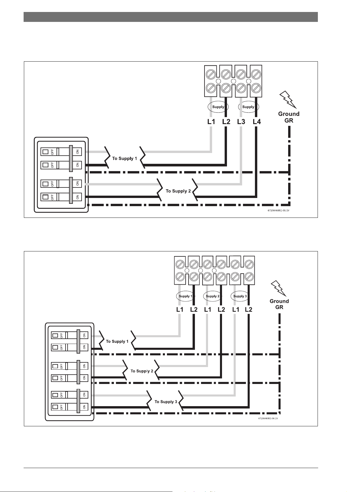
4.5 Electrical connections
WARNING:
B The unit must be wired by a qualified
electrician, in accordance with the
current version of the National Electrical
Code US) or Canadian Electric Code
(Canada).
When the heater is not within sight of the
electrical circuit breakers, a circuit breaker
lockout or additional local means of
disconnection for all non-grounded
conductors must be provided that is within
sight of the appliance. (Ref NEC 422.31.).
B Check the pressure of the main water supply. To
operate correctly, the heater needs the running
pressures mentioned in Tab. 5.
Copyright6 720 646 951 (2011/09)
Page 15
As per the Canadian Electrical Code, C22.102 Section 26-744, an auxiliary terminal
block must be fitted to the heater before
connecting to the electrical supply. This is
available as a kit from Bosch
Thermotechnology Corp. Part Number “AE
Canada Kit”. (Contact 800-798-8161).
US wiring
• The minimum recommended wire size is 8 AWG. (The
terminal block will accept cables up to 6 AWG size).
• The cable entry is via the 1¼ inch cable entry hole on
the bottom right hand edge of the back plate.
• Strip back the insulation on the power wires about
½ inch. Connect the live wires to the terminals
marked “L1” and “L2.” There are two pairs of live
wires in the WH17 and three pairs of live wires in the
WH27. (See Fig. 7 and Fig. 8, page 16).
• Any insulation on the ground wires should be stripped
back about ¾ inch. The ground leads must be
connected to the pillar terminal marked “GR”. (See
Fig. 7 and Fig. 8, page 16).
• Make sure the terminal block screws are tightened
securely. Loose connections can cause wires to heat
up.
• Make sure that the ground wires are wrapped around
its terminal stud and into the saddle washer. The nut
should be tightened securely.
• Attach the front cover and tighten the retaining
screws.
Installation | 15US
6 720 646 951 (2011/09)Copyright
Page 16
16 | Installation US
The WH17 requires two independent 240V AC circuits protected by two separate and independent double pole
breakers (as shown) rated at 40A each.
Fig. 7 WH17 terminal block connection (U.S.A. only)
The WH27 requires three independent 240V AC circuits protected by three separate and independent double pole
breakers (as shown) rated at 40A each.
Fig. 8 WH27 terminal block connection (U.S.A. only)
Copyright6 720 646 951 (2011/09)
Page 17
Installation | 17US
Canada Wiring - auxiliary terminal block and
connections
Fitting the auxiliary terminal block (see diagram below).
Fig. 9 For Canada only (Not for U.S.A.)
Connecting the supply cable - Canada only - not for the
USA.
The WH17 requires an 80A 240V AC
single phase supply protected by an 80A
double pole circuit breaker.
The WH27 requires a 120A 240V AC
single phase supply protected by a 120A
double pole circuit breaker.
• The power cable size and the installation must be in
accordance with the Canadian Electrical Code, C22.1-
02.
• The incoming hole diameter on auxiliary terminal
block can accept up to 1/0 AWG size cables.
• The cable entry is via the 1 ¼ inch cable entry hole on
the bottom right hand edge of the backplate.
• Strip back the insulation on the power wires about
½ inch. Connect the ungrounded conductors to the
terminals “L1” and “L2” on the auxiliary terminal
block.
• Any insulation on the ground wire should be stripped
back about ¾ inch. The ground lead must be
connected to the pillar terminal marked “GR.”
• Make sure the terminal block screws are tightened
securely. Loose connections can cause wires to heat
up.
• Make sure that the ground wire is wrapped around its
terminal stud and into the saddle washer. The nut
should be tightened securely.
• Attach the front cover and tighten the retaining
screws.
Fig. 10 For Canada only (Not for U.S.A.)
B Connect the red wires from the left hand terminal of
the new block to the L1 terminals in the unit. (There
are two red wires required in the WH17 and three in
the WH27).
B Connect the blue wires from the right hand terminal
of the new block to the L2 terminals in the unit.
(There are two blue wires required in the WH17 and
three in the WH27).
B Push and click the auxiliary terminal block onto the
louvered rail in the backplate.
6 720 646 951 (2011/09)Copyright
Page 18
18 | Installation US
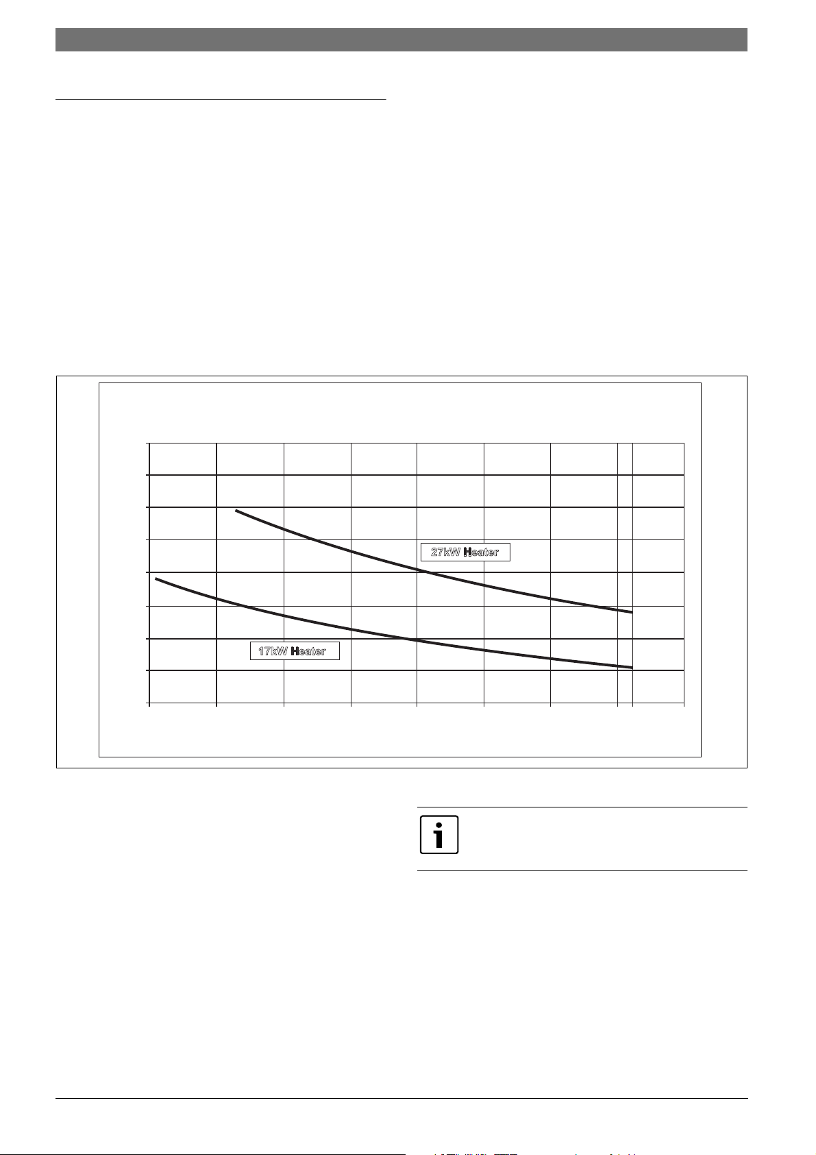
95 100 105 110 130115 120 125 135
1.0
1.5
2.0
2.5
3.0
3.5
4.0
4.5
5.0
Outlettemperature(ºF)
MaxFlowRate(USgal/min)
OutlettemperaturevsMaximumflowratesetting
(basedonincomingwatertemperatureof55ºF)
17kWHeater
27kWHeater
6720646951-09.1V
131
4.6.2 Adjusting the temperature dial
4.6 Starting up
4.6.1 Checking for leaks and purging air
B Verify all circuit breakers supplying power to the
water heater are turned off.
B The temperature adjustment is made using the dial on
the bottom edge of the unit. The adjustment is
between approximately 95 °F and 131 °F. Turning the
dial clockwise increases the temperature setting as
indicated by the marking on the unit.
B Open all hot water taps supplied by the water heater
and inspect all water connections for leaks.
B With all hot water taps still open, inspect each tap to
ensure all air in the lines has been purged out.
B With the air purged and taps still flowing, turn on all
circuit breakers supplying the water heater.
B Close all hot water taps and proceed to the next
section.
4.6.3 Adjusting the flow
B Open fully both inlet and outlet shut-off valves at the
heater, then:
B Turn on fully the highest flowing hot water faucet
(e.g., bathtub) served by the water heater.
B Adjust the outlet shut-off valve until the water flow
rate from the hot faucet corresponds to the value
given in Fig. 11 below.
Fig. 11
For example:
• For the WH17 unit, using the outlet ball valve, ensure
the flow rate does not exceed 2.3 gallons/minute.
• For the WH27 unit, using the outlet ball valve, ensure
Before leaving the site, the installer should
demonstrate the unit to the user and give
them this guide.
the flow rate does not exceed 3.5 gallons/minute.
These figures are based on an inlet water temperature of
55 °F and a supply voltage of 240 volts. If the inlet water
temperature is lower than 55 °F, or if the supply voltage
is less than 240 volts, then the outlet temperature will be
lower than what is shown in Fig. 11. If a higher outlet
water temperature is desired, then reduce the flow rate
and/or supply the unit with 240 volts.
Copyright6 720 646 951 (2011/09)
Page 19
5 Operation instructions
5.1 Before using the water heater
WARNING:
B Do not use the unit if you think it may be
frozen, as this could result in serious
damage to the unit. Wait until you are
sure that it has completely thawed out
before you switch it on.
B Check that the power is switched on at the circuit
breaker panel.
B Turn on the hot water faucet FULLY.
The hot water temperature can be changed
by adjusting the temperature dial on the
bottom surface of the unit. (The dial adjusts
the temperature typically between 95°F and
131°F. The factory sets the temperature dial
at the lowest position).
Operation instructions | 19US
• If the unit has been used recently, run the water
through for a few seconds to let the temperature cool
down. You may initially get a short burst of very hot
water that was in the plumbing lines from previous
use.
• If a second outlet connected to the unit is also turned
on, the hot water will be shared between the two.
6 720 646 951 (2011/09)Copyright
Page 20

20 | Maintenance US
6 Maintenance
Draining the heater
Due to the shape of the heat exchangers and connecting
pipe, it is extremely difficult to get all of the water out of
the heater. Follow the procedure below to best minimize
the chance of freezing:
B Disconnect electric supply.
B Disconnect cold and hot water pipes from fittings on
bottom of heater. Allow water to drain out (have a
catch basin ready).
B After allowing all water to drain out, the heater should
be blown out with low pressure compressed air to
remove as much water as possible from water heater
modules. Bursts of air work better than continuous
flow.
Remember, these suggestions are only made to help
minimize the potential for freeze damage and are not to
be construed as the guaranteed method for dealing with
freeze possibilities.
Check inlet water filter screen once a year
B Check that the power is switched off at the circuit
breaker panel.
B Shut off the installer supplied cold water isolation
valve to the heater. If one is not installed, install
before proceeding.
B Open nearest hot water tap to relieve pressure in the
plumbing lines.
B Position a bucket under the cold water inlet
connection of the heater to catch any water that may
drain.
B Disconnect the cold water plumbing connection from
the inlet (bottom right of heater) to access filter
screen.
B Remove filter, clean with water and inspect for
damage. If the filter is at all damaged, it should be
replaced.
B Replace the filter into the inlet housing
B DO NOT leave the filter out.
B DO NOT remove the flow regulator (located behind
the filter).
B DO NOT clear the filter by back flushing.
B NEVER use an air line to blow out the heater (the flow
transducer will be permanently damaged).
B Before switching power back on, open all hot water
taps and inspect each tap to ensure all air in the lines
has been purged out. With the air purged and taps still
flowing, turn on all circuit breakers supplying the
water heater.
B Close all hot water taps and proceed for normal
operation.
Copyright6 720 646 951 (2011/09)
Page 21
Using an ohmmeter to check for premature element failure
On WH17 model, there is no middle element
Maintenance | 21US
Fig. 12 Heating elements
Meter probes Ohm Readings
Outer to Outer 10.5 ± 0.6 Ohms
Middle to Middle 11.7 ± 0.8 Ohms
Inner to Inner 15.1 ± 1 Ohms
Tab. 8
Meter probes Ohm Readings
Outer to Outer 10.5 ± 0.6 Ohms
Middle to Middle 11.7 ± 0.8 Ohms
Inner to Inner 21.0 ± 1.2 Ohms
Tab. 9
6 720 646 951 (2011/09)Copyright
Page 22
22 | Troubleshooting US
7 Troubleshooting
DANGER: Risk of electric shock!
B Always switch off the electricity supply to
the unit before you remove the cover.
Cold water only – Neon light off
Flow rate is too low Verify the flow rate out of fixture is at or above the minimum activation rate
required for the unit to activate. (Activation rates: WH17 = 0.6 GPM, WH27 = 0.8
GPM).
Plumbing crossover To test for a plumbing crossover, turn off power supply to the heater. Close
installer supplied cold water shut off valve (if none installed, install before
proceeding). Open all hot water taps supplied by the heater. Wait 5 minutes and
check all taps. Any water running is a sign of a plumbing crossover. Consult a local
plumber or service person for help in correcting a plumbing crossover. To return
the heater to service, reinstall cover, open the inlet water supply to the heater and
open all hot water taps. Let all taps run until there is no air coming out of the
fixtures. Shut off all hot water taps. Turn power supply on to the heater. Return
heater to service. (This procedure will prevent the heating elements from burning
out).
The flow transducer is not
spinning
Turn off the power supply to the heater and remove the cover. Observe if the flow
transducer "spins" when the water is turned on. Please note the flow transducer
spins at a high speed and can appear to be stopped when actually spinning. It is
recommended to observe the flow transducer without water flowing, then turn on
a hot water tap while observing the flow transducer. If the flow transducer is not
spinning, remove and flush flow transducer, noting the Do's and Dont's on page 20.
See the technical support section of www.bosch-climate.us for more detailed
instruction on removing the flow transducer.
Important: If you are unable to perform the tasks listed
below, or need additional assistance please contact your
original installer/licensed electrician.
No electricity at the heater
or one of the supplies has
failed
One or more of the heating
module thermal cut-outs
has tripped
The power supply voltage
has dropped
Tab. 10
Have a licensed electrician verify proper wiring and adequate voltage on the
terminal block inside the water heater. See the “Electrical connections” section on
page 14 of this manual.
Turn off the power to the heater, remove the cover and locate the thermal cutouts
on the top of each heating module. Check for continuity through each cutout.
(Less than 0.5 Ohms). A continuity value greater than 0.5 Ohms indicates that the
cutout has tripped or is faulty. A cutout will only trip in exceptional circumstances
and it is essential that the cause is determined and resolved. Verify the heater's
inlet filter screen and all outlets served by the heater are clear of debris. Ensure
the heater is not being fed preheated water. This water heater is designed for cold
water feed only.
Contact Technical Support 800-798-8161 for further instructions.
This is likely an issue with the incoming power supply. Have a qualified electrician
measure voltage on the water heater’s terminal block while operating at maximum
flow and maximum temperature setting. The WH17 & WH27 models are rated for
240V and will also operate at 220V or 208V with reduced maximum flow rate.
Copyright6 720 646 951 (2011/09)
Page 23
Cold water only – Neon light off
Troubleshooting | 23US
The inlet water temperature
is too cold
Verify the heater is sized appropriately for it’s geographic location. Turn
temperature knob located on the bottom of the water all the way clockwise for
maximum temperature setting. Ensure flow rates are within the heater’s
specifications. Refer to Fig. 11 on page 18 of the manual. Use of an isolation valve
on the hot water outlet to control flow rate is recommended.
One of the power supplies
is not on
Have a licensed electrician verify adequate voltage on the terminal block inside the
water heater. Verify circuit breakers serving the heater are not tripped. See the
“Electrical connections” section on page 14 of this manual.
Premature element failure Shut off power to the unit and remove cover. Use an ohmmeter to verify correct
resistance on each element. If readings are different than listed specifications on
page 21, contact Technical Support 800-798-8161 for further instruction.
Tab. 10
Water not hot enough - Neon light on
The water supply is
connected to the outlet of
Verify plumbing connections are correct (See Fig. 2). Reconnect the water supply
to the inlet of the unit (marked blue).
the unit
One or more of the heating
module thermal cut-outs has
tripped
Turn off the power to the heater, remove the cover and locate the thermal cutouts
on the top of each heating module. Check for continuity through each cutout.
(Less than 0.5 Ohms). A continuity value greater than 0.5 Ohms indicates that the
cutout has tripped or is faulty. A cutout will only trip in exceptional circumstances
and it is essential that the cause is determined and resolved. Verify the heater's
inlet filter screen and all outlets served by the heater are clear of debris. Ensure
the heater is not being fed preheated water. This water heater is designed for
cold water feed only.
Contact Technical Support 800-798-8161 for further instructions.
Temperature dial is turned
too low
Turn the temperature dial located on the bottom of the water heater clockwise for
hotter temperatures. Refer to Fig. 11 for outlet temperature vs. flow rate variance.
Water flow is too high Adjust water flow to stay within the water heater’s specifications. See Fig. 11 of
this manual.
Tab. 11
6 720 646 951 (2011/09)Copyright
Page 24
24 | Troubleshooting US
Water flow too low
There are restrictions in the
plumbing
Water supply pressure too
low
Outlet shut-off valves are set
too low
Tab. 12
Water Temperature too Hot
Temperature dial set too
high
Obstructions in the water path can restrict the flow of water through the heater.
Verify the heater’s inlet filter screen, faucet aerators, showerheads and whole
house filters are clear of debris. Verify proper flow on the outlet side of the heater
with the hot water pipe disconnected. Maximum flow rates for each unit are as
follows. WH17 = 2.3gpm, WH27 = 3.5gpm.
Verify incoming water supply is at least 30psi. For people on well systems, the
recommended pressure range is 30-50psi.
Adjust installer supplied outlet valve as described below:
• Completely open both installer supplied inlet and outlet shut-off valves at the
heater. (if none installed, install before proceeding).
• Completely open hot water on the highest flowing hot water fixture served by
the heater (i.e. bathtub).
• Slowly close the outlet shut-off valve, slowing the water flow rate until the
temperature at the hot water faucet corresponds to the values given on Fig. 11
of the manual, or desired water temperature is reached.
Turn the temperature knob located on the bottom of the water heater
counterclockwise for cooler temperatures.
There are restrictions in
the plumbing
Inlet water temperature is
too warm
Tab. 13
Obstructions in the water path can restrict the flow of water through the heater
causing overheating. Verify the heater’s inlet filter screen, faucet aerators,
showerheads and whole house filters are clear of debris. Verify proper flow on the
outlet side of the heater with the hot water pipe disconnected. Opening hot water
isolation valve fully may be necessary. Maximum flow rates for each unit are as
follows. WH17 - 2.3gpm, WH27 - 3.5gpm.
Verify the heater is being feed with cold water only. This water heater is not
designed for preheated water or recirculation applications. Increase flow rate where
ever possible. Replacing low flow showerheads and aerators with higher flowing
(GPM) ones may be necessary.
Copyright6 720 646 951 (2011/09)
Page 25

Water Temperature fluctuates
Troubleshooting | 25US
Cold mix, heater
deactivates
If inlet water temperature is over 70°F, water may be very hot out of the tap. This
requires a lot of cold water to be added in order to get a usable hot water
temperature. The addition of too much cold water will overpower hot water demand
from the water heater. This slows the flow within the water heater, decreasing it
below the activation point, which shuts off the heater. The end result is nothing but
cold water coming out of the outlet. Increase the fl ow rate by cleaning or replacing
fixtures and lower the setting on the temperature adjustment knob.
Fluctuating water pressure If the water pressure in the home is erratic and the water flow is not consistent
while a tap is opened, then the temperature of hot water will fluctuate. The
minimum water pressure for the home should be 30psi or greater. For people on
well systems the minimum pressure range is 30-50psi. The use of a pressure
reducing/regulating valve is an effective way to maintain constant water pressure to
the water heater. Watts brand 25AUB- ¾” or N35B-¾” pressure reducing/regulating
valves or equivalent is suggested.
Changing flow rate.
Water supply connected to
the outlet of the unit.
Major changes in flow rate can adversely affect the output water temperature of the
heater. Increases from one major fixture running to multiple fixtures running at one
time can cause the temperature to fluctuate. Stay within the heater’s specifications.
See Fig. 11.
Tab. 14
6 720 646 951 (2011/09)Copyright
Page 26

6720646951-12.1V
1
3
4
6
7
8
9
10
11
12
2
14
13
5
26 | Spare Parts US
8 Spare Parts
Fig. 13
Copyright6 720 646 951 (2011/09)
Page 27

Spare Parts | 27US
17kW model 27kW model
# Description Part Number Description Part Number
1 PCB mount 8-738-701-722-0 PCB mount 8-738-701-722-0
2 - - Single Triac 8-738-701-733-0
3 Dual Triac 8-738-701-723-0 Dual Triac 8-738-701-723-0
4 1 Pole Thermal Cutout 8-738-701-727-0 2 Pole Thermal Cutout 8-738-701-740-0
5 Element Assembly 2 8-738-701-728-0 Element Assembly 2 8-738-701-736-0
6 Outlet 8-738-701-729-0 Outlet 8-738-701-729-0
7 Element Assembly 1 8-738-701-730-0 Element Assembly 1 8-738-701-737-0
8 Temperature Sensor 8-738-701-731-0 Temperature Sensor 8-738-701-731-0
9 4 way Terminal Block 8-738-701-697-0 6 way Terminal Block 8-738-701-698-0
10 17kW Control PCB 8-738-701-732-0 27kW Control PCB 8-738-701-738-0
11 Flow Sensor 8-738-701-700-0 Flow Sensor 8-738-701-700-0
12 Inlet 8-738-701-734-0 Inlet 8-738-701-734-0
13 Flow Regulator 8-738-701-735-0 Flow Regulator 8-738-701-739-0
14 Filter 8-738-701-706-0 Filter 8-738-701-706-0
Tab. 15
For further information ask your local dealer.
FOR SERVICE AND INSTALLATION QUESTIONS CALL:
Tel: 800-798-8161
Fax: 603-965-7581
Bosch Thermotechnology Corporation
Bosch Thermotechnology Corp.
50 Wentworth Avenue
Londonderry, NH 03053
USA
Phone 800-798-8161
Fax 603-965-7581
www.bosch-climate.us
techsupport@bosch-climate.us
6 720 646 951 (2011/09)Copyright
Page 28

28 | Indice US
Indice
1 Explicación de los símbolos e instrucciones
importantes de seguridad . . . . . . . . . . . . . . . . . 29
1.1 Explicación de los símbolos . . . . . . . . . . . 29
1.2 Instrucciones Importantes de Seguridad . 29
2 Información sobre el calentador . . . . . . . . . . . . 31
2.1 Exención de responsabilidad . . . . . . . . . . 31
2.1.1 Número de aprobación . . . . . . . . . . . . . . . 31
2.2 Identificación del código técnico . . . . . . . 31
2.3 Identificación de nombre y número
de modelo . . . . . . . . . . . . . . . . . . . . . . . . 31
2.4 Contenido del paquete . . . . . . . . . . . . . . . 31
2.5 Diagrama de componentes . . . . . . . . . . . . 32
2.6 Dimensiones . . . . . . . . . . . . . . . . . . . . . . . 33
2.7 Esquema eléctrico . . . . . . . . . . . . . . . . . . 34
2.8 Descripción de funcionamiento . . . . . . . . 35
2.9 Características técnicas . . . . . . . . . . . . . . 36
3 Reglamentos . . . . . . . . . . . . . . . . . . . . . . . . . . . . 37
4 Instalación . . . . . . . . . . . . . . . . . . . . . . . . . . . . . 38
4.1 Información importante . . . . . . . . . . . . . . 38
4.2 Selección del lugar de instalación . . . . . . 38
4.2.1 Prevención de congelamiento . . . . . . . . . . 38
4.2.2 Espacios libres minimos recomendados
para servicio . . . . . . . . . . . . . . . . . . . . . . 39
4.3 Montaje del calentador de agua . . . . . . . . 39
4.4 Conexiones de agua . . . . . . . . . . . . . . . . . 40
4.4.1 Calidad del agua . . . . . . . . . . . . . . . . . . . . 40
4.5 Conexiones eléctricas . . . . . . . . . . . . . . . . 40
4.6 Puesta en marcha . . . . . . . . . . . . . . . . . . . 44
4.6.1 Comprobación de fugas y purga de aire . . 44
4.6.2 Ajuste del control de temperatura . . . . . . 44
4.6.3 Ajuste del flujo . . . . . . . . . . . . . . . . . . . . . 44
5 Instrucciones de funcionamiento . . . . . . . . . . . 45
5.1 Antes de utilizar el calentador de agua . . . 45
6 Mantenimiento . . . . . . . . . . . . . . . . . . . . . . . . . . 46
7 Problemas . . . . . . . . . . . . . . . . . . . . . . . . . . . . . . 48
8 Piezas de repuesto . . . . . . . . . . . . . . . . . . . . . . . 52
Copyright6 720 646 951 (2011/09)
Page 29

Explicación de los símbolos e instrucciones importantes de seguridad | 29US
1 Explicación de los símbolos e instrucciones importantes de
seguridad
1.1 Explicación de los símbolos
Advertencias
Las advertencias se indican en el texto mediante un triángulo de advertencia y un fondo gris.
En caso de peligro por descarga eléctrica, el
signo de exclamación en el triángulo de advertencia se sustituye por un símbolo de un
rayo.
Se utilizan palabras de precaución al inicio de una advertencia para indicar el tipo y la gravedad del riesgo resultante si no se aplican medidas para minimizar los daños.
• AVISO indica que se pueden producir daños menores
a la propiedad.
• ATENCIÓN indica posibles lesiones menores perso-
nales a mediano plazo.
• ADVERTENCIA indica posibles lesiones personales
graves.
• PELIGRO indica que pueden ocurrir lesiones persona-
les graves.
Información importante
Información importante que no presenta
ningún riesgo para las personas o los bienes
se indica con este símbolo. Está separado
por líneas horizontales arriba y abajo del
texto.
Símbolos adicionales
Símbolo Significado
1.2 Instrucciones Importantes de Seguridad
Al utilizar equipos eléctricos, se deben seguir la precauciones básicas de seguridad, incluyendo las siguientes:
B Lea y siga todas las instrucciones.
B Este aparato debe estar conectado a tierra.
B Desconecte este producto del suministro eléctrico
antes de limpiarlo, darle servicio o quitar la cubierta.
B Para reducir el riesgo de lesiones, es necesaria una
estrecha supervisión cuando el producto se utiliza
cerca de niños o personas mayores.
B Advertencia: Monte la unidad sobre una sección plana
de la pared, bien lejos de las posibles salpicaduras de
agua o aerosol y lejos de las zonas húmedas, donde el
contacto con la humedad directa o con lo mojado
puede ocurrir.
B Advertencia: Instalación en interiores solamente,
donde no quede expuesto a la congelación.
B Advertencia: No instale el calentador en un lugar
donde puede estar sujeto a la congelación.
B La instalación eléctrica debe ser conforme a los actua-
les National Electrical Codes.
B Advertencia: Do not switch the heater on if you sus-
pect that it may be frozen. Wait until you are sure that
it has completely thawed out.
B El Tronic 5000C Pro está diseñado para calentar agua
fría potable para uso doméstico. El calentador no está
diseñado para aceptar temperaturas de entrada de
agua por encima de 86°F. Contacte a Bosch Thermotechnology antes de especificar o instalar el aparato
en cualquier otra aplicación.
B secuencia de pasos
→ referencia cruzada a otros puntos de este
documento o de otros documentos
• listado / entrada de la lista
– listado / entrada de la lista (2º nivel)
Tab. 1
6 720 646 951 (2011/09)Copyright
Page 30

30 | Explicación de los símbolos e instrucciones importantes de seguridad US
B Additional Canadian safety instructions:
– De acuerdo con el Código Eléctrico Canadiense,
C22.1-02 Sección 26-744, un bloque de terminales
auxiliar debe ser instalado en la unidad antes de
conectar a la red eléctrica de alimentación (Juego
de Parte N ° "AE Juego Canadá").
(Consulte la Página 17).
– Una terminal verde (o conector con la marca "G",
"GR", "TIERRA", o "TIERRA") se proporciona dentro
de la caja de control. Para reducir el riesgo de descargas eléctricas, conecte esta terminal o conector
a la terminal de tierra del servicio eléctrico del
panel de alimentación con un cable de cobre, de
conformidad con el Código Eléctrico Canadiense,
Parte I.
– Este producto estará protegido por un interruptor
diferencial Class A.
B Guarde este manual en un lugar seguro una vez que la
unidad ha sido instalada, ya que puede ser necesario
para futura referencia.
Copyright6 720 646 951 (2011/09)
Page 31

2 Información sobre el calentador
2.1 Exención de responsabilidad
2.1.1 Número de aprobación
Estado de Massachusetts
En el Estado de Massachusetts un plomero o electricista
con licencia debe realizar la instalación. (Número de
autorización: P1-09-25).
2.2 Identificación del código técnico
EI 17 E/M W I H B
EI 27 E/M W I H B
Información sobre el calentador | 31US
Tab. 2
EI Electrónica Instantánea
17 Máxima salida (kW)
E/M Control mecánico de temperatura
W Colgado a la pared
I Interior
H Instalación horizontal
B Conexiones de agua
2.3 Identificación de nombre y número de
modelo
Nombre de
modelo Número de modelo
WH17 EI 17 E/M W I H B
WH27 EI 27 E/M W I H B
Tab. 3
2.4 Contenido del paquete
• Calentador de agua de paso eléctrico
• 4 tornillos y junta.
6 720 646 951 (2011/09)Copyright
Page 32

32 | Información sobre el calentador US
6720646951-14.1V
G
E
L
J
H
I
N
M
F K
A
D
C
B
2.5 Diagrama de componentes
Fig. 1
A Módulo de calentamiento
B Resistencia
C Panel de control dual Channel
D Salida de agua
E Entrada de agua
F Mando de temperatura
G Transductor de caudal
H Terminal (solamente en CANADA)
I Bloque de terminales
J Sonda de temperatura
K PCI de control
L Disyuntores térmicos
M Filtro
N Regulador de caudal
Copyright6 720 646 951 (2011/09)
Page 33

2.6 Dimensiones
Información sobre el calentador | 33US
Fig. 2
1 Salida de ¾" NPT (agua caliente)
2 Entrada de ¾" NPT (agua fría)
3 Mando de temperatura
4 Diodo Emisor de Luz (LED)
Dimensiones
(pulgadas) WH17 / WH27
A (Ancho) 15 ¼ "
B (Altura) 12 ½ "
C (Profundidad) 4 ½ "
D 12 5/8"
E 12 5/8"
F 2 ½ "
G 3 ½ "
H 6 1/8"
I 5 ¾ "
J 1 ¾ "
Conexiones de
¾ "
Agua
Tab. 4 Dimensiones
6 720 646 951 (2011/09)Copyright
Page 34

34 | Información sobre el calentador US
6720648179-02.1V
Gris
Marrón
Negro
Roja
Roja
Negro
Gris
Marrón
Marrón
PCBvisto
desdeel
ladodela
conexión
(ver/ama)
(ver/ama)
(ver/ama)
Suministro1/2/3
Disyuntor
de
doblepolo
Disyuntor
de
doblepolo
Esquemadeconexión
suministro27kW,3x240V.
Advertencia
apagarelsuministrode
electricidadantesdeproceder
Instalaciónymantenimiento.
Debeserrealizada
solamenteporun
electricistaconlicencia
Tapadelatónizquierda(vistafrontal) Tapadelatónizquierda(vistafrontal)
Roja
Azul
Roja
Roja
Azul
Roja
terminales
Flujo
desdeel
ladodela
conexión
PCBvisto
Roja
Roja
Negro
Marrón
Gris
Azul
Gris
Marrón
Marrón
Azul
Gris
Gris
Marrón
2.7 Esquema eléctrico
PELIGRO: ¡Riesgo de choque eléctrico!
B Apague siempre el suministro de electri-
cidad a la unidad antes de cualquier intervención en el calentador.
Fig. 3 Diagrama interno de cableado para la unidad WH27 de fase sencilla.
Copyright6 720 646 951 (2011/09)
Page 35

Información sobre el calentador | 35US
6720648179-03.1V
Disyuntor
de
únicopolo
Disyuntor
de
únicopolo
Marrón
Negro
Roja
Roja
Negro
Marrón
Azul
Marrón
Flujo
PCBvisto
desdeel
ladodela
conexión
PCBvisto
desdeel
ladodela
conexión
Roja
(ver/ama)
(ver/ama)
(ver/ama)
Tapadelatónizquierda(vistafrontal) Tapadelatónderecha(vistafrontal)
terminales
Esquemadeconexión
suministro17kW,2x240V.
Advertencia
apagarelsuministrode
electricidadantesdeproceder
Instalaciónymantenimiento.
Debeserrealizada
solamenteporun
electricistaconlicencia
Suministro1/2
Azul
Marrón
Marrón
Azul
Azul
Marrón
Marrón
Negro
Fig. 4 Diagrama esquemático interior de cableado para la unidad WH17 de una sola fase.
• Cada módulo calentador está protegido por una corta
2.8 Descripción de funcionamiento
Cómo funciona el calentador de agua:
• The Tronic 5000C Pro calienta el agua continuamente
a medida que fluye a través de los módulos del calentador.
• El control electrónico de PCB controla el caudal y la
temperatura del agua entrante y después cambia en el
número necesario de elementos calefactores para llegar a la temperatura seleccionada mediante el ajuste
del control de temperatura.
• A medida que el caudal o la temperatura del agua de
entrada cambia, el control electrónico ajusta el número de elementos del calentador utilizados para que la
temperatura de salida se mantenga.
• La temperatura de salida del agua puede cambiar lige-
circuito térmico electromecánico. Este corta circuitos
se pondrá en funcionamiento solamente en circunstancias excepcionales.
Contactar el suporte técnico para mas assistencia
800-798-8161.
• La unidad WH17 es suministrada de dos fuentes de
voltaje independientes y la unidad WH27 de tres
suministros de voltaje independientes. (En Canadá, la
unidad tiene solamente una fuente de voltaje).
• Dependiendo de la región del país, la temperatura del
suministro de agua puede variar entre 40 °F en
invierno y 70 °F en verano, con un promedio de 55 °F.
La temperatura de salida y el flujo máximo del calentador depende de la temperatura de entrada de agua.
ramente el caudal de los cambios debidos a lo pasos
en la energía diferentes elementos del calentador se
enciende y se apagan.
• La temperatura del agua de salida también puede
variar si se excede el caudal máximo (ver Fig. 11) o si
elcambia el suministro de voltaje.
6 720 646 951 (2011/09)Copyright
Page 36

36 | Información sobre el calentador US
2.9 Características técnicas
Características técnicas Unidades WH17 WH27
Suministro de voltaje V 2 X 240VAC (Canada 240VAC) 3 X 240VAC (Canada 240VAC)
Amperaje A 2 X 40A (Canada 80A) 3 X 40A (Canada 120A)
Salida máxima kW 17.25kW 26.85kW
Rango de temperatura de control 95 °F to 131 °F 95 °F to 131 °F
Presión de agua mínima psi 15psi 15psi
Presión de agua máxima psi 150psi 150psi
Rango de caudal mínimo gal/min 0.6 US gal / min 0.8 US gal / min
Rango de caudal máximo (ver Fig. 11) (ver Fig. 11)
Peso (sin agua) lbs 20 lbs 22 lbs
La unidade funcionará en suministros de voltaje más bajos, pero se aplicarán os seguientes cambios:
Salida máxima 15kW a 220V 22.5kW a 220V
Rango de caudal máximo
(ver Fig. 11)
Tab. 5
13kW a 208V 20kW a 208V
84% de un máximo de 220V 84% de un máximo de 220V
75% de un máximo de 208V 75% de un máximo de 208V
Copyright6 720 646 951 (2011/09)
Page 37

3 Reglamentos
Se debe cumplir cualquier ley y reglamentos locales
relativos a la instalación y el uso de aparatos eléctricos
calentadores de agua. Por favor, consulte las leyes que
deben ser atendidas en su país.
• La instalación eléctrica debe ajustarse a las actuales
National Electrical Codes.
• De acuerdo con el Código Eléctrico Canadiense,
C22.1-02 Sección 26-744, un bloque de terminales
auxiliar debe ser instalado en la unidad antes de
conectar a la red eléctrica de alimentación (Juego de
Parte N ° "AE Juego Canadá").
• Un terminal verde (ou cablo marcado "G", "GR" ou
"GROUNDING") viene con el aparato. Instrucciones de
seguridad para Canada, para reducir el riesgo de
descargas eléctricas, conecte esta terminal o
conector a la terminal de tierra de servicio eléctrico
del panel de alimentación con un cable de
cobre, de conformidad con el Código Eléctrico
Canadiense, Parte I.
• En Canadá, este producto deberá estar protegido por
un interruptor de circuito Clase A para fallas a tierra.
• En el estado de Massachusetts un plomero o un
electricista debe realizar la instalación. (Número de
autorización: P1-09-25).
• En el Estado de Massachusetts un plomero con
licencia debe instalar una válvula de alivio de presión
en el lado del agua fría. (MGL 142 Sección 19, Número
de autorización P1-09-25).
• La unidad debe ser conectada por un electricista
calificado, de acuerdo con la versión actual del
Código Eléctrico Nacional EE.UU.) o el Código
Eléctrico Canadiense (Canadá).
• Cuando el calentador no está a la vista de los
interruptores de circuito eléctrico, un interruptor de
circuitos u otra forma de desconexión local para
todos los conductores sin puesta a tierra debe estar
siempre a la vista del aparato. (Ref. NEC 422.31.).
• El tamaño del cable de alimentación y la instalación
debe estar de acuerdo con el Código Eléctrico
Canadiense, C22.1-02.
Reglamentos | 37US
ADVERTENCIA:
La Proposición 65 de California enumera las
sustancias químicas conocidas en el estado
de causar cáncer, defectos de nacimiento,
muerte, enfermedad grave u otros daños reproductivos. Este producto puede contener
tales sustancias, ya sea su origen a partir de
la combustión de combustibles (gas, petróleo) o los componentes de este producto.
6 720 646 951 (2011/09)Copyright
Page 38

38 | Instalación US
4 Instalación
PELIGRO: ¡Riesgo de choque eléctrico!
B Por razones de seguridad, desconecte el
cable de suministro eléctrico al aparato
antes de llevar a cabo cualquier prueba o
mantenimiento.
ADVERTENCIA:
B Este aparato debe tener tierra física de
acuerdo con la edición más reciente del
National Electrical Code. NFPA 70. En Canadá, todo el alambrado eléctrico debe
cumplir con los reglamentos locales y el
Canadian Electrical Code, CSA C22.1
Parte 1.
4.1 Información importante
PELIGRO:
B La instalación sólo debe ser realizada por
una persona calificada de acuerdo con
estas instrucciones.
B Bosch Thermotechnology Corp. no se
hace responsable de los aparatos que no
estén bien instalado
ADVERTENCIA:
B El aparato sólo debe ser montado en una
posición vertical con las conexiones de
agua situadas en la parte inferior del calentador. Bajo ninguna circunstancia el
calentador debe ser montado de manera
diferente.
ADVERTENCIA:
B El aparato debe estar ubicado en un área
donde las fugas de calor o conexiones no
dañen el área adyacente al aparato o los
pisos bajos de la estructura.
Por favor siga estas instrucciones. Si no lo hace puede
resultar en:
• Daños o lesiones.
• Instalación y/o funcionamiento inadecuado.
• Pérdida de la garantía.
4.2 Selección del lugar de instalación
ADVERTENCIA: ¡Riesgo de congelación!
B No instale el calentador de agua en una
zona donde existe la posibilidad de congelación. Los daños al calentador de agua
como resultado de congelación no serán
cubiertos por la garantía.
• Si se utiliza en un lugar público, coloque el calentador
lejos de un fácil acceso para impedir vandalismo.
• Instale la unidad en una sección plana de la pared,
lejos de las posibles salpicaduras de agua o de rocío y
• lejos de las zonas húmedas, donde pueda ocurrir contacto directo con lo húmedo o mojado.
• Instale el calentador en un lugar que ofrezca un fácil
acceso para cualquier servicio o mantenimiento.
4.2.1 Prevención de congelamiento
ADVERTENCIA:
B LA ELECTRICIDAD ES MUY PELIGROSA.
TOME PRECAUCIONES ADICIONALES Y
ASEGÚRESE QUE TODOS INTERRUPTORES DE CIRCUITOS ESTÁN APAGADOS
ANTES DE REALIZAR CUALQUIER TRABAJO AL CALENTADOR.
ADVERTENCIA:
B No instale el calentador en un lugar don-
de puede estar sujeto a la congelación.
Introducción
Tenga en cuenta que el manual de instalación indica que
el calentador de agua no debe instalarse en un lugar
donde pueden estar expuestos a temperaturas de congelación. Si el calentador se debe dejar en un espacio
que puede experimentar temperaturas bajo cero, toda el
agua debe ser drenada de éste. Vea la Sección 6.
Las fallas por congelación no están cubiertas por la
garantía.
No se permite el uso de agentes tales como
el anticongelante, ya que pueden causar daños a los componentes internos del calentador de agua.
Copyright6 720 646 951 (2011/09)
Page 39

4.2.2 Espacios libres minimos recomendados para
servicio
Si fuera necesario el servicio del Pro 5000C Tronic,
observe las siguientes distancias. No son necesarios
espacios libres, pero facilita la labor de servicio.
Instalación | 39US
4.3 Montaje del calentador de agua
ADVERTENCIA:
B El aparato debe ser instalado en la orien-
tación que se muestra en la Fig. 6 es decir, montado en posición vertical con los
accesorios de agua en la parte inferior
del calentador. Bajo ninguna circunstan-
cia se debe montar el calentador de manera diferente.
B Afloje los tornillos de sujeción en la cubierta frontal y
tome la cubierta del calentador. Sostenga la placa
posterior en posición contra la pared y marque los
cuatro orificios de montaje de montaje.
B Taladre los orificios y fije el calentador con los cuatro
tornillos para madera suministrados.
Fig. 5 Distancias mínimas
WH17 WH27
Superior (A) 12" 12"
Lados 0" 0"
Parte inferior (B) 6" 6"
Parte inferior (C) 12" 12"
Tab. 6 Distancias mínimas
Fig. 6 Posición de montaje vertical
6 720 646 951 (2011/09)Copyright
Page 40

40 | Instalación US
4.4.1 Calidad del agua
4.4 Conexiones de agua
ADVERTENCIA:
B No instale una válvula de retención de no
retorno dentro de los 10 pies de la entrada.
ADVERTENCIA:
B No aplique calor o soldadura a las co-
nexiones o tuberías si ya están conectadas a la unidad.
AVISO:
B En el Estado de Massachusetts se instala-
rá una válvula de alivio de presión en el
lado de agua fría por un plomero con licencia. (MGL 142 Sección 19, Número de
aprobación P1-09-25).
B El calentador debe estar conectado directamente al
suministro principal de agua fría y no con agua pre
calentada. (La temperatura del agua no debe ser
mayor a 86 °F).
B El calentador se debe instalar con válvulas de cierre
en la entrada y salida de las conexiones.
B Se recomienda el uso de cobre de ¾ pulgada o media
pulgada o conexiones flexibles de alta presión.
B No utilizar tuberías de plástico a menos de 3 metros a
cada lado del calentador.
B Utilice cinta de teflón para sellar las roscas. NO use
lubricante de tubería.
B Recuerde que debe mantener la tubería de agua
caliente lo más corto que sea posible.
Después de que el calentador ha sido sondeado, y
antes de de que instale el cableado, enjuague con
agua para eliminar cualquier residuo o partículas sueltas. El calentador debe estar lleno de agua y purgado
el aire antes de activar el encendido. Si no lo hace
puede dar lugar a daños en el producto que no son
cubiertos por la garantía.
B Después de lavado y llenado de agua el calentador,
(con la energía apagada) desconecte la conexión de
entrada e inspeccione el filtro de cualquier residuo
que pueda haber sido eliminado por el sistema.
Las conexiones de entrada y salida están
claramente marcadas en el calentador. Cada
una tiene un conector NPT de ¾ de pulgada.
La calidad del agua puede tener un impacto en la longevidad del aparato y puede anular la garantía del fabricante.
B Para llevar a cabo un análisis de agua, llame a su
departamento local de aguas, o si está en un aljibe,
haga que el agua de éste sea analizado periódicamente.
Si la calidad del agua excede uno o más de los valores
que se especifican a continuación, Bosch recomienda
consultar a un profesional local en tratamiento de
agua para conocer las opciones de suavizado y/o
acondicionado.
Descripción Niveles Máximos
pH pH 6.5 - 8.5
TDS
(Total de sólidos dissuel-
tos)
Dureza total mg/l or ppm
mg/l or ppm 500
100
Aluminio mg/l or ppm 2.0
Cloruros mg/l or ppm 250
Cobre mg/l or ppm 1.0
Hierro mg/l or ppm 0.3
Manganeso mg/l or ppm 0.05
Zinc mg/l or ppm 5.0
Table 7
4.5 Conexiones eléctricas
ADVERTENCIA:
B El aparato debe ser conectado por un
técnico electricista, de acuerdo con la
versión actual del National Electrical
Code de los EE.UU.) o el Canadian Electric Códe (Canadá).
Cuando el calentador no está a la vista de
los disyuntores eléctricos, un interruptor de
circuito o otra forma local de desconexión
de todos los conductores que no están a tierra se debe asumir que están a la vista el
aparato. (Ref. NEC 422.31.).
B Revise la presión del suministro principal de agua.
Para que funcione correctamente, el calentador necesita las presiones de operación mencionadas en
la Tab. 5.
Copyright6 720 646 951 (2011/09)
Page 41

De acuerdo con el Código Eléctrico Canadiense, C22.1-02 Sección 26-744, un bloque
terminal auxiliar debe ser instalado en el calentador antes de conectar a la red eléctrica. Esto está disponible como un kit de
Bosch Termotecnia Corp. Número de pieza
"AE Kit de Canadá ". (Contacto 800-798-
8161).
Cableado EE.UU
• El calibre mínimo recomendado es de 8 AWG. (El blo-
que de terminales aceptará cables de hasta 6 AWG).
• La entrada de cables se realiza a través del cable de
1¼ pulgada en el orifico de entrada del borde inferior
derecho de la placa trasera.
• Pele el aislamiento de los cables de alimentación
aproximadamente ½ pulgada. Conecte los cables con
corriente a las terminales marcadas "L1" y "L2." Hay
dos pares de cables con corriente en los pares WH17
y tres de cables con corriente en la WH27. (Vea la
Fig. 7 y Fig. 8, page 16).
• Cualquier aislamiento de los cables de tierra debe ser
pelado alrededor de ¾ de pulgada. Los conductores
de tierra deben estar conectados a la terminal de
poste con la marca "GR". (Vea la Fig. 7 y Fig. 8, page
16).
• Asegúrese de que los tornillos del bloque de termina-
les estén apretados de forma segura. Las conexiones
sueltas pueden causar que los cables se calienten.
• Asegúrese de que los cables de tierra se envuelven
alrededor de su clavija terminal y en la arandela de
montura. La tuerca debe estar bien apretada.
• Coloque la cubierta delantera y apriete la los tornillos
de retención.
Instalación | 41US
6 720 646 951 (2011/09)Copyright
Page 42

42 | Instalación US
El WH17 requiere de dos circuitos independientes de CA 240V protegidos por dos cortacircuitos separados e
independientes de dos polos (como se muestra) cada uno de 40A nominal.
Fig. 7 WH17 conexión de la placa terminal (sólo para EE.UU.)
El WH27 requiere de tres circuitos independientes de CA 240V protegida por tres cortacircuitos separados e
independientes de dos polos (como se muestra) cada uno de 40A nominal.
Fig. 8 WH27 conexión de la placa terminal (sólo para EE.UU.)
Copyright6 720 646 951 (2011/09)
Page 43

Instalación | 43US
Cableado para Canadá - bloque de terminales auxiliares y conexiones
Montaje del bloque de terminales auxiliares (ver el
siguiente diagrama).
Fig. 9 Para Canadá (no para EE.UU.)
B Pulse y haga clic en el bloque auxiliar de terminales en
el riel de persianas en la placa posterior.
Conexión del cable de alimentación - Canadá - no para
Estados Unidos.
El WH17 requiere un suministro de CA 240V
80A monofásico protegido por un cortacircuitos de dos polos 80A.
El WH27 requiere un suministro de 240V AC
120A monofásico protegido por un cortacircuitos de dos polos 120A.
• El tamaño del cable de alimentación y de la instalación debe estar en conformidad con el Código Eléctrico Canadiense, C22.1-02.
• El diámetro del orificio de entrada en el bloque auxiliar terminal puede aceptar cables hasta de tamaño 1
/ 0 AWG.
• La entrada de cables se realiza a través del cable de 1
¼ de pulgada en el orificio de entrada en el borde
inferior derecho de la placa posterior.
• Pele el aislamiento de los cables de alimentación
aproximadamente ½ pulgada. Conecte los conductores sin conexión a tierra a los terminales "L1" y "L2" en
el bloque terminal auxiliar.
• Cualquier aislamiento del cable de tierra debe ser
pelado alrededor de ¾ inch. El cable de tierra debe
estar conectado a la terminal de poste con la marca
"GR."
• Asegúrese de que los tornillos del bloque de terminales estén apretados de forma segura. Las conexiones
sueltas pueden causar que los cables se calienten.
• Asegúrese de que el cable de tierra se envuelve alrededor de su clavija terminal y en la arandela de montaje. La tuerca debe estar bien apretada.
• Coloque la cubierta delantera y apriete la los tornillos
de retención.
Fig. 10 Para Canadá (no para EE.UU.)
B Conecte los cables rojos de la terminal del lado
izquierdo de el nuevo bloque a las terminales L1 en la
unidad. (Hay dos cables rojos requeridos en el WH17
y tres en el WH27).
B Conecte los cables azules de la terminal del lado dere-
cho del nuevo bloque a las terminales L2 en la unidad.
(Hay dos cables azules requeridos en el WH17 y tres
en la WH27).
6 720 646 951 (2011/09)Copyright
Page 44

44 | Instalación US
95 100 105 110 130115 120 125 135
1.0
1.5
2.0
2.5
3.0
3.5
4.0
4.5
5.0
Tomadetemperatura(ºF)
Máximocaudal(gal/min)
Temperaturadesalidafrentealajustedelcaudalmáximo
(basadoenlatemperaturadelaguadeentradade55ºF)
Calentadorde 17kW
Calentadorde 27kW
6720648179-09.1V
131
4.6.2 Ajuste del control de temperatura
4.6 Puesta en marcha
4.6.1 Comprobación de fugas y purga de aire
B Verifique que todos los interruptores de circuito que
suministran energía al calentador de agua, estén apagados.
B El ajuste de temperatura se realiza mediante el con-
trol en el borde inferior de la unidad. El ajuste es
aproximadamente entre 95 °F y 135 °F. Al girar el control en el sentido de las manecillas del reloj aumenta
la temperatura como es indicado por la marca de la
unidad.
B Abra todas las llaves de agua caliente suministrada
por el calentador de agua e inspeccione todas las
conexiones de agua por fugas.
B Con todas las llaves de agua caliente aún abiertos, ins-
peccione cada llave para asegurarse de que todo el
aire en las líneas ha sido expulsado.
B Con el aire purgado y las llaves aún fluyendo, abra
todos los interruptores de circuito que suministran el
calentador de agua.
B Cierre todos las llaves de agua caliente y proceda a la
4.6.3 Ajuste del flujo
B Abra completamente las válvulas de cierre de entrada
y salida-en el calentador, entonces:
B Abra completamente la llave de agua caliente con más
caudal(por ejemplo, la bañera) servido por el calentador de agua.
B Ajuste la válvula de cierre de salida hasta que el rango
de flujo de agua caliente corresponde con el valor en
la Fig. 11 siguiente.
siguiente sección.
Fig. 11
Por ejemplo:
• Para la unidad WH17, usando la válvula de bola de
salida, asegúrese de que el caudal no supere los 2,3
galones / minuto.
• Para la unidad WH27, usando la válvula de bola de
salida, asegúrese de que el caudal no supere los 3,5
galones / minuto.
Estas cifras se basan en una temperatura de agua de
entrada de 55 °F y una alimentación de 240 voltios. Si la
temperatura de entrada de agua es inferior a 55 °F, o si
la alimentación de voltaje es menor de 240 voltios,
entonces la temperatura de salida será inferior a lo que
se muestra en la Fig. 11. Si se desea una toma de mayor
temperatura de agua, a entonces, reduzca el rango de
flujo y / o suministro de la unidad con 240 voltios.
Antes de abandonar el sitio, el instalador
debe demostrar la unidad al usuario y entregarles esta guía.
Copyright6 720 646 951 (2011/09)
Page 45

5 Instrucciones de funcionamiento
5.1 Antes de utilizar el calentador de agua
ADVERTENCIA:
B No utilice la unidad si cree que puede
congelarse ya que esto podría resultar en
serios daños a la unidad. Espere hasta
que esté seguro de que se descongele
completamente antes de ponerla en marcha.
B Compruebe que la unidad se encuentra activada en el
panel interruptor.
B Abra COMPLETAMENTE la llave de agua caliente.
La temperatura del agua caliente se puede
cambiar ajustando el control de temperatura en la superficie inferior de la unidad. (El
disco selector ajusta la temperatura por lo
general entre 95°F y 131°F. La fábrica establece el control de temperatura en la posición más baja).
Instrucciones de funcionamiento | 45US
• Si la unidad ha sido utilizada recientemente, deje
correr el agua través de ésta unos segundos para
dejar que baje la temperatura. En un inicio se puede
obtener una corta ráfaga de agua muy caliente que
estaba en las cañerías de los usos previos.
• Si además se abre una segunda llave conectada a la
unidad el agua caliente será compartida entre las dos.
6 720 646 951 (2011/09)Copyright
Page 46

46 | Mantenimiento US
6 Mantenimiento
Vaciado del calentador
Debido a la forma de los intercambiadores de calor y la
tubería de conexión, es muy difícil conseguir extraer
toda el agua del calentador. Siga el procedimiento para
reducir al mínimo las posibilidades de congelamiento:
B Desconecte el suministro eléctrico.
B Desconecte las tuberías de agua fría y caliente de las
conexiones en la parte inferior del calentador. Deje
que el agua drene hacia afuera (tenga lista una cubeta
de captura).
B Después de permitir que toda el agua drene hacia
afuera, el calentador se debe soplar con baja presión
de aire comprimido para eliminar la mayor cantidad
de agua posible de los módulos calentadores de agua.
Las ráfagas de aire funcionan mejor que el flujo
continuo.
Recuerde que estas sugerencias se hacen solamente
para ayudar a minimizar la posibilidad de daños por congelación y no debe interpretarse como el método garantizado para hacer frente a las posibilidades de
congelación.
B Antes de conectar la alimentación de nuevo, abra
todas las llaves de agua caliente e inspeccione cada
llave para asegurarse que todo el aire en las líneas ha
sido expulsado. Con el aire la purgado y las llaves aún
fluyendo, encienda todos los interruptores de circuito
que alimentan el calentador de agua.
B Cierre todos las llaves de agua caliente y proceda a la
operación normal.
Compruebe la pantalla del filtro de agua de entrada
una vez al año
B Compruebe que la energía está apagada en el panel
interruptor.
B Cierre el aislamiento de la válvula de agua fría que se
suministra con el instalador al calentador. Si está instalado, instale uno antes de continuar.
B Abra la llave de agua caliente más cercano para aliviar
la presión en las líneas de conducción.
B Coloque una cubeta debajo de la conexión de la
entrada de agua fría del calentador para recoger el
agua que puede drenar.
B Desconecte la línea de conducción de agua fría de la
entrada (parte inferior derecha del calentador) para
acceder al filtro de pantalla.
B Quite el filtro, limpie con agua y verifique que no haya
daños. Si el filtro está completamente dañado, hay
que remplazarlo.
B Vuelva a colocar el filtro en la entrada de la cubierta
B NO deje el filtro afuera.
B NO quite el regulador de flujo (que se encuentra
detrás del filtro).
B NO limpie el filtro, mediante descarga inversa.
B NUNCA use una línea de aire para apagar el calentador
(el flujo transductor será permanentemente dañado).
Copyright6 720 646 951 (2011/09)
Page 47

Uso de un óhmetro para comprobar fallas prematuras en el elemento
En el modelo WH17 no hay ningún elemento
central.
Mantenimiento | 47US
Fig. 12 Elementos de calefacción
Mediciones Lecturas de Ohmios
Exterior a Exterior 10.5 ± 0.6 Ohmios
Medio a Medio 11.7 ± 0.8 Ohmios
Interior a Interior 15.1 ± 1 Ohmios
Tab. 8
Mediciones Lecturas de Ohmios
Exterior a Exterior 10.5 ± 0.6 Ohmios
Medio a Medio 11.7 ± 0.8 Ohmios
Interior a Interior 21.0 ± 1.2 Ohmios
Tab. 9
6 720 646 951 (2011/09)Copyright
Page 48

48 | Problemas US
7 Problemas
PELIGRO: ¡Riesgo de choque eléctrico!
B Antes de trabajar en la parte eléctrica,
cortar siempre la corriente eléctrica.
Solamente agua fría - luces de neón apagadas
El caudal es demasiado bajo Compruebe que el rango de salida del caudal del accesorio está en o por encima
del rango mínimo de activación necesario para activar la unidad. (Rangos de activación: WH17 = 0.6 GPM, WH27 = 0.8 GPM).
Cruce de líneas de conducción
Para probar un cruce de líneas de conducción, corte el suministro de energía al
calentador. Cierre la válvula de cierre que se suministra son la instalación (si no
hay ninguna instalada, instálela antes de proceder). Abra todos las llaves de agua
caliente, a la que suministra el calentador. Espere 5 minutos y revise todas las llaves. Cualquier agua que esté corriendo es signo de un cruce de líneas de conducción. Consulte a un plomero local o personal de servicio para ayudar en la
corrección de un cruce de líneas de conducción. Para volver el calentador a servicio, vuelva a instalar la cubierta, abra el suministro de agua de entrada al calentador y abra todas las llaves de agua caliente. Deje que todas las llaves funcionen
hasta que no haya aire que saliendo de los accesorios. Cierre todas las llaves de
agua caliente. Encienda el suministro de energía al calentador. Regrese el calentador a servicio. (Este procedimiento evitará que los elementos de calefacción se
quemen).
Important: Si usted no puede realizar las tareas que se
enumeran a continuación, o necesita asistencia adicional, por favor póngase en contacto con un instalador original / electricista con licencia.
El transductor de flujo no
está girando
No hay electricidad en el
calentador o uno de los
suministros ha fallado
Uno o más de los módulos
de interruptores térmicos
se ha disparado
Apague la fuente de energía del calentador y retire la cubierta. Observe si el transductor de flujo "gira" cuando la llave de agua está abierta. Tenga en cuenta que el
transductor de flujo gira a una velocidad alta y puede parecer estar detenido
cuando en realidad está girando. Se recomienda observar el transductor de flujo,
sin agua corriente, a continuación, abra una llave de agua caliente mientras se
observa el transductor de flujo. Si el transductor de flujo no está girando, quite y
lave el transductor de flujo, teniendo en cuenta los Si y No en la page 20. See the
technical support section of www.bosch-climate.us for more detailed instruction
on removing the flow transducer.
Haga que un electricista con licencia verifique el correcto cableado y el voltaje adecuada en el bloque de terminales en el interior del calentador de agua. Vea la sección "Conexión eléctrica" en la page 14 de este manual.
Apague el aparato, retire la cubierta e localice los disyuntores térmicos en cima de
las resistencias eléctricas de calentamiento. Verifique la continuidad de casa
disyuntor térmico (menor que 0.5 Ohms). Un valor mas grande que 0.5 Ohms
indica que el disyuntor térmico enteja bloqueado ó quebrado. Un disyuntor térmico
solamente bloquea en circunstancias excepcionales, y queda esencial que la causa
sea bien identificada. Verificar que los filtros de agua estén limpios, y que la
entrada de agua no tenga agua caliente. Este aparato funciona solamente con agua
fría.
Contacte el suporte técnico 800-798-8161 para mas instrucciones.
La alimentación de voltaje
se ha reducido
Tab. 10
Esto es probablemente un problema con la fuente de alimentación de entrada.
Haga que un electricista calificado mida el voltaje en el bloque de terminales del
calentador de agua al funcionar a máximo flujo y temperatura máxima. Los modelos
WH17 y WH27 han sido diseñados para 240V y también funcionará a 220V o 208V
con flujo máximo
reducida.
Copyright6 720 646 951 (2011/09)
Page 49

Solamente agua fría - luces de neón apagadas
Problemas | 49US
La temperatura del agua de
entrada es demasiado fría
Compruebe que el calentador es de tamaño apropiado para su ubicación geográfica. Gire el mando de la temperatura en la parte inferior del agua totalmente en el
sentido de las manecillas del reloj para establecer la temperatura máxima. Asegúrese que los rangos de flujo dentro del calentador están dentro de las especificaciones. Consulte la Fig. 11 en la page 18 del manual. Se recomienda el uso de una
válvula de aislamiento en la salida de agua caliente para el control de velocidad de
flujo.
Una de las fuentes de alimentación no está encendida
Haga que un electricista con licencia compruebe el voltaje adecuado en el bloque
de terminales dentro del calentador de agua. Verifique que los interruptores que
sirven al calentador no se han disparado. Consulte la Sección "Conexión eléctrica"
en la page 14 de este manual.
Falla prematura del elemento
Desconecte la corriente a la unidad y quite la cubierta. Utilice un medidor de resistencia para verificar la correcta resistencia de cada elemento. Si las lecturas son
diferentes a las especificaciones que figuran en la page 21, póngase en contacto
con Soporte Técnico 800-798-8161 para obtener más instrucciones.
Tab. 10
El agua no calienta lo suficiente - Luces de neón encendidas
El suministro de agua está
conectado a la toma de la
unidad
Compruebe que las conexiones de las líneas de conducción son correctas (Ver
Fig. 2). ). Vuelva a conectar el suministro de agua a la entrada de la unidad (marcada en azul).
Uno o más de los módulos
de interruptores térmicos se
ha disparado
El control de temperatura de
disco está activado demasiado bajo
El flujo de agua es demasiado grande
Tab. 11
Apague el aparato, retire la cubierta e localice los disyuntores térmicos en cima de
las resistencias eléctricas de calentamiento. Verifique la continuidad de casa
disyuntor térmico (menor que 0.5 Ohms). Un valor mas grande que 0.5 Ohms
indica que el disyuntor térmico enteja bloqueado ó quebrado. Un disyuntor térmico solamente bloquea en circunstancias excepcionales, y queda esencial que la
causa sea bien identificada. Verificar que los filtros de agua estén limpios, y que la
entrada de agua no tenga agua caliente. Este aparato funciona solamente con agua
fría.
Contacte el suporte técnico 800-798-8161 para mas instrucciones.
Gire el control de disco de temperatura en la parte inferior de la derecha del calentador de agua para temperaturas más calientes. Consulte la Fig. 11 para la temperatura de salida vs variación del caudal.
Ajuste el flujo de agua para mantenerse dentro de las especificaciones del calentador de agua. Vea la Fig. 11 de este manual.
6 720 646 951 (2011/09)Copyright
Page 50

50 | Problemas US
Flujo de agua demasiado bajo
Existen restricciones en las
líneas de conducción
Presión del agua de alimentación demasiado baja
Salida de las válvulas de cierre establecidas demasiado
bajo
Tab. 12
Las obstrucciones en el trayecto del agua pueden restringir el flujo de agua a través del calentador. Verifique que la pantalla del filtro de entrada, llaves, duchas y
todos los filtros de la casa estén libres de escombros. Verificar el flujo correcto en
el lado de salida del calentador con la tubería de agua caliente desconectada. La
velocidad máxima de flujo para cada unidad es como sigue. WH17 = 2.3gpm ,
WH27 = 3.5gpm.
Verifique que el suministro de agua de entrada sea de por lo menos 30psi. Para
quienes tienen sistemas de aljibe, el rango de presión recomendada es de 3050psi.
Ajuste la válvula de salida que se suministra don la instalación como se describe a
continuación:
• Abra completamente ambas válvulas de cierre-de entrada y salida que se suministran con la instalación en el calentador. (si no hay ninguna instalada, instálelas antes de proceder).
• Abra completamente el agua caliente en la llave de agua caliente con más alto
flujo a la que le da servicio el calentador (por ejemplo, la bañera).
• Cierre lentamente la salida de la válvula de cierre, disminuyendo el caudal de
agua hasta que la temperatura en la llave de agua caliente se corresponda con
los valores indicados en la Fig. 11 del manual, o se alcance la temperatura
deseada del agua.
La temperatura del agua está demasiado caliente
Control de temperatura
demasiado alto
Hay restricciones en las
líneas de conducción
Gire el control de la temperatura en la parte inferior del calentador de agua en sentido contrario a las manecillas del reloj para temperaturas más frías.
Las obstrucciones en el trayecto de agua puede restringir el flujo de agua a través
del calentador causando el recalentamiento. Verifique que la pantalla del filtro de
entrada del calentador, llaves, duchas y los filtros para toda la casa estén libres de
escombros. Verificar el flujo correcto de la salida lateral del calentador con la tubería
de agua caliente desconectada. Apertura de agua caliente puede ser necesaria una
válvula de aislamiento total. La velocidad máxima de flujo para cada unidad es como
sigue. WH17 - 2.3gpm, WH27 - 3.5gpm.Z
La temperatura de entrada
de agua es demasiado
caliente
Compruebe que el calentador es alimentado sólo con agua fría. Este calentador de
agua no está diseñado para aplicaciones de agua precalentada o recirculación.
Aumente la velocidad de flujo siempre que sea posible. Sustitución de duchas de
bajo flujo y aireadores con mayor flujo (GPM) las que sean necesarias.
Tab. 13
Copyright6 720 646 951 (2011/09)
Page 51

La temperatura del agua fluctúa
Problemas | 51US
Mezcla en frío, el calentador se desactiva
Variaciones de presión de
agua
Cambio de rango de flujo.
Abastecimiento de agua
conectado a la salida de la
unidad.
Tab. 14
Si la temperatura del agua esté a más de 70°F, , el agua puede estar muy caliente
fuera de la llave. Esto requiere agregar una gran cantidad de agua fría con el fin de
obtener temperatura de agua caliente útil. La adición de demasiada agua fría
domina la demanda de agua caliente del calentador de agua. Esto disminuye el flujo
en el calentador de agua, disminuyéndolo por debajo del punto de activación, lo
cual apaga el calentador. El resultado final no es más que agua fría que sale de la
llave. Aumente la velocidad de flujo mediante la limpieza o sustitución de llaves y
disminuyendo el ajuste de la perilla de temperatura.
Si la presión del agua en el hogar es irregular y el flujo de agua no es coherente
mientras que se abre una llave, entonces, la temperatura del agua caliente fluctuará.
La presión mínima de agua para el hogar debe ser 30psi o mayor. Para las personas
que cuentan con sistemas de aljibe la presión mínima es de 30-50psi. El uso de una
válvula de reducción o regulación es una forma efectiva para mantener la presión
constante de agua al calentador de agua. Se sugieren válvulas marca Watts 25AUB
de ¾” o N35B-¾” de reducción de presión / regulación o equivalentes.
Los principales cambios en el rango de flujo puede afectar negativamente la temperatura del agua de salida del calentador. El aumento a partir de una llave principal
abierta para varios accesorios funcionando a un mismo tiempo puede hacer que la
temperatura fluctúe. Manténgase dentro de las especificaciones del calentador. Vea
la Fig. 11.
6 720 646 951 (2011/09)Copyright
Page 52

52 | Piezas de repuesto US
1
3
4
6
7
8
9
10
11
12
2
14
13
5
8 Piezas de repuesto
Fig. 13
Copyright6 720 646 951 (2011/09)
Page 53

Piezas de repuesto | 53US
17kW model 27kW model
# Description Part Number Description Part Number
1 Tapa de suporte del panel de control 8-738-701-722-0 Tapa de suporte del panel de control 8-738-701-722-0
2 - - Panel de control 1 8-738-701-733-0
3 Panel de control dual Channel 8-738-701-723-0 Panel de control dual Channel 8-738-701-723-0
4 Disyuntores térmicos 8-738-701-727-0 Disyuntores térmicos 8-738-701-740-0
5 Resistencia 8-738-701-728-0 Resistencia 8-738-701-736-0
6 Salida de agua 8-738-701-729-0 Salida de agua 8-738-701-729-0
7 Resistencia 8-738-701-730-0 Resistencia 8-738-701-737-0
8 Sonda de temperatura 8-738-701-731-0 Sonda de temperatura 8-738-701-731-0
9 Bolque de terminales 8-738-701-697-0 Bolque de terminales 8-738-701-698-0
10 PCI de control 17kW 8-738-701-732-0 PCI de control 27kW 8-738-701-738-0
11 Transductor de caudal 8-738-701-700-0 Transductor de caudal 8-738-701-700-0
12 Entrada de agua 8-738-701-734-0 Entrada de agua 8-738-701-734-0
13 Filtro 8-738-701-735-0 Filtro 8-738-701-739-0
14 Regulador de caudal 8-738-701-706-0 Regulador de caudal 8-738-701-706-0
Tab. 15
Para más información consulte con su distribuidor local.
PARA PREGUNTAS DE SERVICIO E INSTALACIÓN:
LLAME AL Tel: 800-798-8161
Fax: 603-965-7581
Bosch Thermotechnology Corporation
Bosch Thermotechnology Corp.
50 Wentworth Avenue
Londonderry, NH 03053
Phone 800-798-8161
Fax 603-965-7581
www.bosch-climate.us
techsupport@bosch-climate.us
6 720 646 951 (2011/09)Copyright
Page 54

54 | Sommaire US
Sommaire
1 Explication des symboles et instructions de
sécurité importantes . . . . . . . . . . . . . . . . . . . . . 55
1.1 Explication des symboles . . . . . . . . . . . . . 55
1.2 Importantes instructions de sécurité . . . . 55
2 Informations relatives au chauffe-eau . . . . . . . . 57
2.1 Clause de non responsabilité . . . . . . . . . . 57
2.1.1 Numéro d'approbation . . . . . . . . . . . . . . . 57
2.2 Code d'identification technique . . . . . . . . 57
2.3 Nom du modèle et numéro
d'identification . . . . . . . . . . . . . . . . . . . . . 57
2.4 Contenu du carton . . . . . . . . . . . . . . . . . . 57
2.5 Schéma des composants . . . . . . . . . . . . . 58
2.6 Dimensions . . . . . . . . . . . . . . . . . . . . . . . . 59
2.7 Schéma de cablage . . . . . . . . . . . . . . . . . . 60
2.8 Function . . . . . . . . . . . . . . . . . . . . . . . . . . 61
2.9 Spécifications techniques . . . . . . . . . . . . . 62
3 Règlementations . . . . . . . . . . . . . . . . . . . . . . . . . 63
4 Installation . . . . . . . . . . . . . . . . . . . . . . . . . . . . . 64
4.1 Informations importantes . . . . . . . . . . . . . 64
4.2 Choix de l'emplacement d'installation . . . 64
4.2.1 Prévention contre le gel . . . . . . . . . . . . . . 64
4.2.2 Espace libre minimum recommandé
pour les services d'entretien . . . . . . . . . . 65
4.3 Montage du chauffe-eau . . . . . . . . . . . . . . 65
4.4 Raccordements d'eau . . . . . . . . . . . . . . . . 66
4.4.1 Qualité de l'eau . . . . . . . . . . . . . . . . . . . . . 66
4.5 Branchements électriques . . . . . . . . . . . . 66
4.6 Mise en marche . . . . . . . . . . . . . . . . . . . . 70
4.6.1 Contrôle des fuites et purge de l'air . . . . . 70
4.6.2 Réglage de la température . . . . . . . . . . . . 70
4.6.3 Réglage du débit . . . . . . . . . . . . . . . . . . . . 70
5 Instructions d'utilisation . . . . . . . . . . . . . . . . . . 71
5.1 Avant toute utilisation du chauffe-eau . . . 71
6 Maintenance . . . . . . . . . . . . . . . . . . . . . . . . . . . . 72
7 Diagnostic de pannes . . . . . . . . . . . . . . . . . . . . . 74
8 Pièces de remplacement . . . . . . . . . . . . . . . . . . 78
Copyright6 720 646 951 (2011/09)
Page 55

Explication des symboles et instructions de sécurité importantes | 55US
1 Explication des symboles et instructions de sécurité importan-
tes
1.1 Explication des symboles
Avertissements
Les avertissements sont indiqués dans le
texte par un triangle de signalisation dans
un cadre gris.
En cas de danger de choc électrique, le
point d'exclamation du triangle de signalisation est remplacé par le symbole d'un éclair.
Le terme Avertissement au début d'un avertissement est
utilisé pour indiquer le type de danger plus ou moins
sérieux si des mesures de minimisation du risque ne
sont pas prises.
• NOTE indique un risque mineur pour la propriété.
• ATTENTION indique un risque éventuel de blessure
mineure à importante aux personnes.
• AVERTISSEMENT indique un risque éventuel de bles-
sure grave aux personnes.
• DANGER indique un risque de blessure grave aux per-
sonnes.
Informations importantes
Les informations importantes qui ne présentent pas de risque pour les personnes ni
pour la propriété sont indiquées avec ce
symbole (I). Elles sont délimitées par des lignes horizontales en haut et en bas du texte.
Symboles supplémentaires
Symbole Signification
B Séquence des étapes
1.2 Importantes instructions de sécurité
Lors de l'utilisation de cet appareil électrique, des précautions de sécurité de base doivent toujours être suivies, y compris les précautions suivantes:
B LIRE ET SUIVRE TOUTES LES INSTRUCTIONS.
B Cet appareil doit être relié à la terre.
B Couper l'alimentation électrique du chauffe-eau avant
de nettoyer, de réparer ou de retirer le capot.
B Afin de réduire le risque de blessure, une vigilance
accrue est nécessaire lorsque le produit est utilisé à
proximité d'enfants ou de personnes âgées.
B Avertissement : Monter l'unité sur une section de mur
plat, à l'abri de tout risque d'éclaboussures ou de
vaporisation et également éloigné de zones présentant un risque de contact avec de la moisissure ou de
l'humidité.
B Avertissement : Ne pas installer le chauffe-eau dans
un endroit présentant un risque de gel.
B Avertissement : ne pas installer de clapet de non
retour ou tout autre type de clapet de transfert à
moins de 10 pieds de l'orifice d'entrée d'eau froide.
B L'installation électrique doit être conforme aux Codes
électriques nationaux actuels.
B Avertissement : Ne pas établir l'alimentation électri-
que de l'appareil s'il existe un soupçon de gel. Attendre jusqu'à être sûr que l'unité est complètement
décongelée.
B Le Tronic 5000C Pro est conçu pour de l'eau froide
potable à usage domestique. Avertissement : Ne pas
installer le chauffe-eau dans un endroit présentant un
risque de gel 86° F. Contacter Bosch Thermotechnology Corp. avant designer ou utiliser l'appareil pout
toute autre application.
→ Renvoi vers d'autres points dans ce docu-
ment ou dans d'autres documents
• Listing/liste
– Listing/liste (2nd niveau)
Tab. 1
6 720 646 951 (2011/09)Copyright
Page 56

56 | Explication des symboles et instructions de sécurité importantes US
B Instructions de sécurité canadiennes
supplémentaires
– Conformément au Code électrique canadien,
C22.1-02 Section 26-744, un bornier auxiliaire doit
être fixé à l'unité avant le branchement à l'alimentation électrique (Pièce du kit N° " Kit Canada AE ").
(Voir Page 17).
– Une borne verte (ou capuchon de connexion mar-
qué " G ", " GR ", " GROUND " ou " GROUNDING ")
est fournie avec le boîtier de commandes. Afin de
réduire le risque de choc électrique, connecter
cette borne ou le connecteur à la borne de terre du
tableau électrique avec un fil de cuivre continu,
conformément au Code électrique canadien, Partie
I.
– Ce produit doit être protégé par un différentiel de
classe A.
B Conserver ce manuel dans un endroit sûr une fois
l'unité installée afin de pouvoir le consulter à tout
moment dans le futur.
Copyright6 720 646 951 (2011/09)
Page 57

2 Informations relatives au chauffe-eau
2.1 Clause de non responsabilité
2.1.1 Numéro d'approbation
État du Massachusetts
Conformément aux conditions d'installation de ce produit dans l'État du Massachusetts, une soupape de surpression côté eau froide doit être installée par un
plombier agréé, MGL 142 Section 19. (Numéro d'approbation P1-09-25).
2.2 Code d'identification technique
EI 17 E/M W I H B
Informations relatives au chauffe-eau | 57US
EI 27 E/M W I H B
Tab. 2
EI Électronique instantané
17 Puissance maximum (kW)
E/M Contrôle de la température mécanique
W Suspendu
I Intérieur
H Installation horizontale
B Raccordements eau
2.3 Nom du modèle et numéro d'identifi-
cation
Nom du modèle Numéro d'identification
WH17 EI 17 E/M W I H B
WH27 EI 27 E/M W I H B
Tab. 3
2.4 Contenu du carton
• Chauffe-eau électrique sans réservoir.
• 4 vis et joints statiques.
6 720 646 951 (2011/09)Copyright
Page 58

58 | Informations relatives au chauffe-eau US
6720646951-14.1V
G
E
L
J
H
I
N
M
F K
A
D
C
B
2.5 Schéma des composants
Fig. 1
A Module de chauffage
B Assemblage des réchauffer
C Boitier de contrôle dual chanel
D Sortie eau chaude
E Admission eau froide
F Bouton
G Capteur de débit
H Terminal (seulement en CANADA)
I Plaque à bornes
J Sensor de température
K Circuit imprimé de commande
L Coupe-circuits thermiques
M Filtre
N Régulateur de débit
Copyright6 720 646 951 (2011/09)
Page 59

2.6 Dimensions
Informations relatives au chauffe-eau | 59US
Fig. 2
1 Sortie ¾" NPT (eau chaude)
2 Entrée ¾" NPT (eau froide)
3 Bouton de température
4 LED
Dimensions
(pouces) WH17 / WH27
A (Largeur) 15 ¼ "
B (Hauteur) 12 ½ "
C (Profondeur) 4 ½ "
D 12 5/8"
E 12 5/8"
F 2 ½ "
G 3 ½ "
H 6
1
/8"
I 5 ¾ "
J 1 ¾ "
Raccords d’eau ¾ "
Tab. 4 Dimensions
6 720 646 951 (2011/09)Copyright
Page 60

60 | Informations relatives au chauffe-eau US
6720648180-02.1V
Gris
Gris
Nior
Marron
Gris
Gris
(vert/jau)
Noir
Noir
Marron
Couverclesdelaitondegauche(vuefrontale)
Alimentation1/2/3
Schémadecâblage27kW,
alimentation3x240V.
Attention:
couperl'alimentation
électriqueavanttoute
installationetentretiende
serviceàexécuter
exclusivementpar
unélectricienagréé.
(vert/jau)
Rouge
Coupe
circuit
2pôles
Coupe
circuit
2pôles
Débit
Couverclesdelaitondedroite(vuefrontale)
Bornier
Cartesdecircuits
imprimésvuedu
côtébranchement
Cartesdecircuits
imprimésvuedu
côtébranchement
Rouge
Rouge
Rouge
Rouge
Bleu
Bleu
Marron
Marron
Rouge
Blue
(vert/jau)
Gris
Marron
Marron
Bleu
Gris
Marron
Rouge
Rouge
2.7 Schéma de cablage
DANGER : Risque de choc électrique!
B Toujours couper l'alimentation électrique
de l'unité avant toute intervention sur le
chauffe-eau.
Fig. 3 Schéma de câblage interne pour l'unité monophasée WH27.
Copyright6 720 646 951 (2011/09)
Page 61

Informations relatives au chauffe-eau | 61US
6720648180-03.1V
PCBvisto
desdeel
ladodela
conexión
(vert/jau)
Coupe
circuit
unipolaire
Coupe
circuit
unipolaire
Marron
Rouge
Noir
Noir
Marron
Rouge
Rouge
Marron
Bleu
Cartesdecircuits
imprimésvuedu
côtébranchement
Cartesdecircuits
imprimésvuedu
côtébranchement
(vert/jau)
Couverclesdelaitondegauche(vuefrontale)
Couverclesdelaitondedroite(vuefrontale)
Débit
Bornier
Alimentation1/2
Schémadecâblage17kW,
alimentation2x240V.
Attention:
couperl'alimentation
électriqueavanttoute
installationetentretiende
serviceàexécuter
exclusivementpar
unélectricienagréé.
(vert/jau)
Noir
Bleu
Marron
Bleu
Marron
Marron
Bleu
Marron
Fig. 4 Schéma de câblage interne pour l'unité monophasée WH17.
2.8 Function
Mode de fonctionnement du chauffe-eau:
• Le Tronic 5000C Pro chauffe l'eau de manière conti-
• La carte de circuit imprimé de contrôle électronique
• Le débit ou la température de l'eau à l'entrée peut
• La température de l'eau à la sortie peut être légère-
• La température de l'eau à la sortie peut également
nue tandis qu'elle s'écoule dans les modules du
chauffe-eau.
surveille le débit ainsi que la température de l'eau à
l'entrée et commute sur le nombre requis de résistances électriques afin d'atteindre la température établie
sur le cadran de réglage de la température.
varier. Par conséquent, le contrôle électronique règle
le nombre de résistances utilisées afin de maintenir la
température de l'eau à la sortie.
ment modifiée en fonction du changement du débit
dû aux échelons de puissance lorsque les résistances
sont mises en marche et arrêtées.
varier si le débit maximum est dépassé (see
ou si la tension d'alimentation est modifiée.
Fig. 11)
• Chaque module du chauffe-eau est protégé par un
protecteur thermique électromécanique. Ce protecteur thermique ne fonctionne qu'en cas de circonstances exceptionnelles.
Contacter le service aprés ventes 800-798-8161 pour
touts renseignements.
• L'unité WH17 est alimentée par deux tensions indé-
pendantes et l'unité WH27 par trois tensions indépendantes (au Canada, l'unité ne présente qu'une
seule tension).
• En fonction de la région, la température de l'eau à
l'entrée peut varier entre 40 °F en hivers et 70 °F en
été, avec une moyenne de 55 °F. La température de
sortie et le débit maximal du chauffe-eau dépendent
de la température de l'eau à l'entrée.
6 720 646 951 (2011/09)Copyright
Page 62

62 | Informations relatives au chauffe-eau US
2.9 Spécifications techniques
Caractéristiques techniques Unités WH17 WH27
Tension V 2 X 240VAC (Canada 240VAC) 3 X 240VAC (Canada 240VAC)
Amperage A 2 X 40A (Canada 80A) 3 X 40A (Canada 120A)
Puissance maximale kW 17.25kW 26.85kW
Température de fonctionnement 95 °F à 131 °F 95 °F à 131 °F
Pression d'eau minimale psi 15psi 15psi
Pression d'eau maximale psi 150psi 150psi
Débit minimum gal/min 0.6 US gal / min 0.8 US gal / min
Débit maximum (voir Fig. 11) (voir Fig. 11)
Poids (sans eau) lbs 20 lbs 22 lbs
L’unité fonctionnera avec des tensions d’alimentation plus faibles, néanmois, les modifications suivantes
s’appliqueront:
Puissance maximale 15kW à 220V 22.5kW à 220V
13kW à 208V 20kW à 208V
Débit maximum
(Voir Fig. 11)
Tab. 5
84% au maximum à 220V 84% au maximum à 220V
75% au maximum à 208V 75% au maximum à 208V
Copyright6 720 646 951 (2011/09)
Page 63

3 Règlementations
Toutes les lois et règlementations relatives à
l'installation et à l'utilisation des chauffe-eau électriques
doivent être appliquées. Veuillez vous renseigner sur les
lois en vigueur dans votre pays.
• L'installation électrique doit être conforme aux Codes
électriques nationaux en vigueur.
• Conformément au Code électrique canadien, C22.102 Section 26-744, un bornier auxiliaire doit être fixé
à l'unité avant le branchement à l'alimentation
électrique (Pièce du kit N° " Kit Canada AE ").
• Le terminal vert (connexion marquée "G", "GR",
"GROUD" ou "GROUNDING") est inclu dans la boite
electronique. Selon les instrucitons de securité
Canadien, pour réduire le risque de choc électrique,
connecter cette borne ou le connecteur à la borne de
terre du tableau électrique avec un fil de cuivre
continu, conformément au Code électrique canadien,
Partie I.
• Ce produit doit être protégé par un différentiel de
classe A.
• Dans l'État du Massachusetts, un plombier ou un
électricien agréé doit exécuter l'installation. (Numéro
d'approbation P1-09-25).
• Dans l'État du Massachusetts une soupape de
surpression côté eau froide doit être installée par un
plombier agréé, (MGL 142 Section 19, numéro
d'approbation P1-09-25).
• L'unité doit être raccordée par un électricien qualifié,
conformément à la version en vigueur du National
Electrical Code (États-Unis) ou du Code électrique
canadien (Canada).
• Lorsque le chauffe-eau ne se trouve pas à proximité
des disjoncteurs, un bloque disjoncteur ou des
moyens de déconnexion locaux pour les conducteurs
non mis à la terre doivent être installés à proximité de
l'appareil. (Réf NEC 422.31.).
• La taille du câble d'alimentation et l'installation
doivent être conformes au Code électrique canadien,
C22.1-02.
Règlementations | 63US
AVERTISSEMENT :
La California Proposition 65 énumère les
substances chimiques reconnues par l’état
de Californie comme cancérigènes, à l’origine de malformations à lanaissance, de
morts, de maladies graves ou d’autres problèmes reproductifs. Ce produit peut contenir de telles substances, que leur origine
soit par la combustion d’un carburant (gaz,
huile) ou les pièces du produit lui-même.
6 720 646 951 (2011/09)Copyright
Page 64

64 | Installation US
4 Installation
DANGER : Risque de choc électrique!
B Pour des raisons de sécurité, couper l'ali-
mentation électrique du chauffe-eau
avant toute intervention technique ou
contrôle d'essai.
AVERTISSEMENT :
B Ce chauffe-eau doit être mis à la terre,
conformément à la version la plus récente du Code électrique national NFPA 70.
Au Canada, toutes les liaisons électriques
au chauffe-eau doivent être conformes
aux codes locaux et au Code électrique
canadien, CSA C22.1 Partie 1.
4.1 Informations importantes
DANGER :
B Seule une personne qualifiée est habili-
tée à exécuter l'installation, conformément aux présentes instructions
B Bosch Thermotechnology Corp. n'est en
aucun cas responsable de la mauvaise
installation des appareils.
AVERTISSEMENT :
B Le chauffe-eau ne peut être installé qu'en
position verticale avec les raccords d'eau
en bas. Il ne peut en aucun cas être installé différemment.
AVERTISSEMENT :
B L'appareil doit être installé dans une
zone dans laquelle les fuites du chauffeeau ou des raccords ne risquent pas d'endommager la zone adjacente à l'appareil
ni les étages inférieurs de la structure.
Veuillez suivre ces instructions à la lettre. Dans le cas
contraire, les risques sont les suivants:
• Dommages ou blessures.
• Mauvaise installation/mauvais fonctionnement.
• Perte de garantie.
4.2 Choix de l'emplacement d'installation
AVERTISSEMENT : Risque de gel!
B Ne pas installer le chauffe-eau dans une
zone qui présente un risque de gel. Tout
dommage sur le chauffe-eau provoqué
par le gel n'est pas couvert par la garantie.
• En cas d'installation dans un espace public, placer le
chauffe-eau dans un endroit difficile d'accès afin de
décourager tout acte de vandalisme.
• Monter l'unité sur une section de mur plat, à l'abri de
tout risque d'éclaboussures ou de vaporisation et également éloigné de zones présentant un risque de
contact avec de la moisissure ou de l'humidité.
• Installer le chauffe-eau dans un endroit facile d'accès
pour les services d'entretien et de maintenance.
4.2.1 Prévention contre le gel
AVERTISSEMENT :
B L'ÉLECTRICITÉ EST EXTRÊMEMENT DAN-
GEREUSE. PRENDRE TOUTES LES PRECAUTIONS QUI S'IMPOSENT ET VÉRIFIER
QUE TOUS LES COUPE-CIRCUITS SONT
FERMÉS AVANT TOUTE INTERVENTION
TECHNIQUE SUR LE CHAUFFE-EAU.
AVERTISSEMENT :
B Ne pas établir l'alimentation électrique
de l'appareil s'il existe un soupçon de gel.
Attendre jusqu'à être sûr que l'unité est
complètement décongelée.
Introduction
Veuillez noter que le guide d'installation indique que le
chauffe-eau ne peut en aucun cas être installé dans un
endroit où il risque d'être exposé au gel. Si le chauffeeau doit être placé dans un endroit risquant des conditions de gel, il doit être totalement vidangé. Voir
Section 6.
Les dommages relatifs au gel ne sont pas couverts par
la garantie.
L'utilisation d'agents toxiques comme l'antigel est interdit. En effet, cela risquerait d'endommager les composants internes du
chauffe-eau.
Copyright6 720 646 951 (2011/09)
Page 65

4.2.2 Espace libre minimum recommandé pour les
services d'entretien
Lorsque des services d'entretien sont requis pour le Tronic 5000C Pro, veuillez observer les espaces libres
recommandés suivants. Il ne s'agit pas d'espaces libres
obligatoires, mais ceux-ci permettent de faciliter le travail d'entretien.
Installation | 65US
4.3 Montage du chauffe-eau
AVERTISSEMENT :
B Le chauffe-eau ne peut être installé que
conformément à l'orientation présentée
Fig. 6 i.e., c'est-à-dire, en position verticale avec les raccords d'eau en bas. Le
chauffe-eau ne peut en aucun cas être
installé d'une autre manière.
B Dévisser les vis de fixation à l'avant du capot et sépa-
rer le capot du chauffe-eau. Maintenir la plaque arrière en position le long du mur et marquer les quatre
trous de fixation.
B Percer les trous et fixer le chauffe-eau à l'aide des
quatre vis à bois fournies.
Fig. 5 Espace libre minimum recommandé
WH17 WH27
Haut (A) 12" 12"
Côtés 0" 0"
Bas (B) 6" 6"
Face (C) 12" 12"
Tab. 6 Espace libre minimum recommandé
Fig. 6 Montage en position verticale
6 720 646 951 (2011/09)Copyright
Page 66

66 | Installation US
4.4.1 Qualité de l'eau
4.4 Raccordements d'eau
AVERTISSEMENT :
B Ne pas installer de clapet de non retour à
moins de 10 pieds de l'orifice d'entrée.
AVERTISSEMENT :
B Ne pas chauffer ni souder les raccords ou
les tuyaux si ceux-ci sont déjà connectés
à l'unité.
AVIS : Clause de non responsabilité
B Dans l'État du Massachusetts, il est re-
commandé de faire installer une soupape
de surpression côté eau froide par un
plombier agréé, (MGL 142 Section 19,
Numéro d'approbation P1-09-25).
B Le chauffe-eau doit être directement connecté à l'ali-
mentation d'eau générale et non à l'eau pré chauffée.
(La température de l'eau à l'entrée ne doit pas être
supérieure à 86 °F).
B Le chauffe-eau doit être installé avec un robinet de
sectionnement sur les raccords d'entrée et de sortie.
B Il est recommandé d'utiliser des raccords cuivre flexi-
bles ou haute pression de ¾ ou pouces.
B Ne pas utiliser de tuyau plastique à 3 pieds de chaque
côté du chauffe-eau.
B Utiliser du ruban Téflon pour l'étanchéité des fileta-
ges. Ne JAMAIS utiliser de pâte lubrifiante.
B La conduite d'eau chaude doit être le plus court pos-
sible.
Une fois les travaux de plomberie terminés et avant le
branchement à l'alimentation électrique du chauffeeau, le rincer à l'eau pour éliminer tout débris ou particule. Le chauffe-eau doit être rempli d'eau et purgé
avant d'établir l'alimentation électrique. Faute de
quoi, le produit risque des dommages qui ne sont pas
couverts par la garantie.
B Après avoir rincé et rempli le chauffe-eau d'eau, (ali-
mentation électrique coupée), déconnecter le raccord d'entrée et vérifier qu'aucun débris acheminé
par le système ne se trouve sur la grille du filtre.
Les raccords d'entrée et de sortie sont indiqués de façon précise sur le chauffe-eau. Ils
ont chacun un raccord NPT de ¾ pouces.
B Contrôler la pression de l'arrivée d'eau. Pour fonction-
ner correctement, les pressions admissibles sont celles indiquées dans le Tab. 5.
La qualité de l'eau peut avoir un impact sur la longévité
de l'appareil et peut ne pas être couverte par la garantie
du fabricant.
B Pour obtenir les données d'analyse de l'eau, veuillez
contacter votre compagnie distributrice des Eaux
locale. En cas d'utilisation d'un puits, veuillez faire
analyser l'eau du puits régulièrement.
ISi la qualité de l'eau excède une ou plusieurs des
valeurs référencées ci-après, Bosch recommande de
consulter un professionnel du traitement des eaux
pour obtenir des options d'adoucissement/conditionnement de l'eau.
Description Niveaux maximum
pH pH 6.5 - 8.5
TDS
(Matières totales dis-
soutes)
Dureté totale mg/l ou ppm
mg/l ou ppm 500
100
Aluminum mg/l ou ppm 2.0
Chlorures mg/l ou ppm 250
Cuivre mg/l ou ppm 1.0
Ferq mg/l ou ppm 0.3
Manganèse mg/l ou ppm 0.05
Zinc mg/l ou ppm 5.0
Table 7
4.5 Branchements électriques
AVERTISSEMENT :
B Un électricien qualifié doit procéder au
branchement électrique conformément à
la version courante du National Electrical
Code (États-Unis) ou au Code électrique
canadien (Canada).
Lorsque le chauffe-eau ne se trouve pas à
proximité des disjoncteurs, un bloque disjoncteur ou des moyens de déconnexion locaux pour les conducteurs non mis à la terre
doivent être installés à proximité de l'appareil. (Réf NEC 422.31.).
Copyright6 720 646 951 (2011/09)
Page 67

Conformément au Code électrique canadien, C22.1-02 Section 26-744, un bornier
auxiliaire doit être fixé au chauffe-eau avant
le branchement à l'alimentation électrique.
Cette fonction est disponible sous forme de
kit de Bosch Thermotechnology Corp. N° du
kit " Kit Canada AE ". (Contactez le 800-798-
8161).
Branchement électrique aux États-Unis
• La taille minimale recommandée pour les câbles est
de 8 AWG. (Le bornier accepte des câbles jusqu'à 6
AWG).
• L'arrivée du câble se fait par le trou d'entrée des
câbles de 1¼ pouces, situé dans le coin en bas à
droite de la plaque arrière.
• Dénuder l'isolation des câbles électriques sur environ
½ pouces. Connecter les fils électriques aux bornes
marquées " L1 " et " L2 ". Le WH17 a deux paires de
fils électriques et le WH27, trois paires. (Voir Fig. 7 et
Fig. 8, page 16).
• Toutes les isolations des fils de terre doivent être reti-
rées sur environ ¾ pouces. Les câbles de masse doivent être raccordés à la borne à trou marquée " GR ".
(Voir Fig. 7 et Fig. 8, page 16).
• Vérifier que les vis du bornier sont vissées à fond. Les
raccords lâches risquent de provoquer la surchauffe
des câbles.
• Vérifier que les fils de terre sont bien enroulés autour
de leur borne et dans la rondelle de selle. L'écrou doit
être bien serré.
• Fixer le capot et visser les vis de fixation.
Installation | 67US
6 720 646 951 (2011/09)Copyright
Page 68

68 | Installation US
Le modèle WH17 requiert deux circuits 240V CA indépendants protégés par deux coupe-circuits 2 pôles séparés et
indépendants (comme indiqué) avec une puissance nominale de 40A chacun.
Fig. 7 Connexion au bornier WH17 (États-Unis seulement)
Le WH27 requiert trois circuits 240V CA indépendants protégés par trois coupe-circuits 2 pôles séparés et
indépendants (comme indiqué) avec une puissance nominale de 40A chacun.
Fig. 8 Connexion au bornier WH27 (États-Unis seulement)
Copyright6 720 646 951 (2011/09)
Page 69

Installation | 69US
Branchement électrique au Canada - bornier auxiliaire
et connexions
Installation du bornier auxiliaire (voir schéma ci-dessous).
Fig. 9 Pour le Canada uniquement (pas pour les États-
Unis.)
B Connecter les fils bleus de la borne de droite du nou-
veau bornier aux bornes L2 de l'unité. (Deux fils bleus
sont requis pour le modèle WH17 et trois pour le
WH27).
B Pousser le bornier jusqu'au fond et le fixer dans le rail
à ailettes de la plaque arrière.
Connexion du câble d'alimentation - Pour le Canada
seulement - pas pour les États-Unis
Le modèle WH17 requiert une alimentation
monophasée 80A 240V CA protégée par un
coupe-circuit 2 pôles de 80A.
Le modèle WH27 requiert une alimentation
monophasée 120A 240V CA protégée par un
coupe-circuit 2 pôles de 120A.
• La taille du câble d'alimentation et l'installation doivent être conformes au Code électrique canadien,
C22.1-02.
• Le diamètre du trou d'entrée du bornier auxiliaire
peut accepter des câbles jusqu'à 1/0 AWG.
• L'arrivée du câble se fait par le trou d'entrée des câbles de 1 ¼ pouces situé dans le coin en bas à droite
de la plaque arrière.
• Dénuder l'isolation des câbles électriques sur environ
½ pouces. Connecter les conducteurs non mis à la
terre aux bornes marquées " L1 " et " L2 " du bornier
auxiliaire.
• Toutes les isolations du fil de terre doivent être retirées sur environ ¾ pouces. Le câble de masse doit
être raccordé à la borne à trou marquée " GR "
• Vérifier que les vis du bornier sont vissées à fond. Les
raccords lâches risquent de provoquer la surchauffe
des câbles.
• Vérifier que le fil de terre est bien enroulé autour de
sa borne et dans la rondelle de selle. L'écrou doit être
bien serré.
• Fixer le capot et visser les vis de fixation.
Fig. 10 Pour le Canada uniquement (pas pour les États-
Unis.)
B Connecter les fils rouges de la borne de gauche du
nouveau bornier aux bornes L1 de l'unité. (Deux fils
rouges sont requis pour le modèle WH17 et trois pour
le WH27).
6 720 646 951 (2011/09)Copyright
Page 70

70 | Installation US
95 100 105 110 130115 120 125 135
1.0
1.5
2.0
2.5
3.0
3.5
4.0
4.5
5.0
Températureàlasortie (ºF)
Débitmaxi.(usgal/min)
Températuredel'eauàlasortieparrapportaudébitmaximum
(basésurlatempératuredel'eauàl'entréede55ºF)
Chauffe-eau 17kW
Chauffe-eau 27kW
6720648180-09.1V
131
4.6.2 Réglage de la température
4.6 Mise en marche
4.6.1 Contrôle des fuites et purge de l'air
B Vérifier que tous les disjoncteurs qui alimentent le
chauffe-eau sont arrêtés.
B Ouvrir les robinets d'eau chaude alimentés par le
B Le réglage de la température s'effectue au moyen du
cadran situé en bas de l'unité. Le réglage admissible
est entre 95 °F et 131 °F. Tourner le cadran dans le
sens des aiguilles d'une montre pour augmenter la
température, comme indiqué par le marquage sur
l'unité.
chauffe-eau et vérifier l'absence de fuite sur tous les
raccords.
B Laisser les robinets ouverts et contrôler chaque
piquage afin de vérifier que les conduites ont toutes
été correctement purgées.
B Lorsque l'air est purgé et toujours avec les robinets
ouverts, mettre en marche les disjoncteurs qui alimentent en eau chaude.
B Fermer tous les robinets d'eau chaude et passer à la
4.6.3 Réglage du débit
B Ouvrir à fond les robinets de sectionnement d'entrée
et de sortie, puis:
B Ouvrir à fond le robinet d'eau chaude le plus haut (par
ex. : la baignoire) alimenté par le chauffe-eau;
B Régler le robinet de sectionnement de sortie jusqu'à
ce que le débit du robinet d'eau chaude corresponde
à la valeur indiquée sur la Fig. 11 ci-dessous.
section suivante.
Fig. 11
Par exemple:
• En ce qui concerne le modèle WH17, l'utilisation d'une
vanne à bille sur le circuit de sortie permet de limiter
le débit à 2,3 gallons/minute.
• En ce qui concerne le modèle WH27, l'utilisation d'une
vanne à bille sur le circuit de sortie permet de limiter
le débit à 3,5 gallons/minute.
Ces chiffres sont basés sur une température de l'eau à la
sortie de 55 °F et une tension d'alimentation de 240
volts. Si la température de l'eau à l'entrée est inférieure
à 55 °F, ou si la tension d'alimentation est inférieure à
240 volts, la température à la sortie sera inférieure aux
données indiquées Fig. 11. Réduire le débit et/ou alimenter l'unité avec du 240 volts si une température à la
sortie plus élevée est souhaitée.
Avant de quitter le site, l'installateur doit décrire en détail l'unité à l'utilisateur et lui donner ce guide.
Copyright6 720 646 951 (2011/09)
Page 71

5 Instructions d'utilisation
5.1 Avant toute utilisation du chauffe-eau
AVERTISSEMENT :
B Ne pas utiliser l'unité s'il y a eu un risque
de gel. Cela risque d'entrainer de sérieux
dommages. Attendre jusqu'à être sûr que
l'unité est complètement décongelée
avant de la mettre en marche.
B Vérifier que l'alimentation électrique du chauffe-eau
est établie sur le tableau électrique.
B Ouvrir À FOND le robinet d'eau chaude.
La température de l'eau chaude peut être
ajustée au moyen du cadran de réglage, en
bas de l'unité. Le cadran permet de régler la
température entre 95°F et 131°F. (Les réglages d'usine sont configurés à la température
la plus basse).
Instructions d'utilisation | 71US
• Si l'unité a été récemment utilisée, laisser couler l'eau
pendant quelques secondes pour permettre à la température de baisser. L'eau se trouvait dans les conduites depuis la dernière utilisation et peut être brulante
au début.
• Si une seconde sortie raccordée à l'unité est également ouverte, l'eau chaude sera partagée entre les deux
sorties.
6 720 646 951 (2011/09)Copyright
Page 72

72 | Maintenance US
6 Maintenance
Vidange du chauffe-eau
La forme des échangeurs thermiques et de la conduite
de raccord rend extrêmement difficile la vidange totale
du chauffe-eau. Veuillez suivre la procédure ci-après
pour minimiser au maximum le risque de gel:
B Couper l'alimentation électrique du chauffe-eau.
B Déconnecter toutes les conduites d'eau chaude et
froide des raccords de tuyauterie situés en bas du
chauffe-eau. Laisser couler l'eau (placer une bassine
en dessous).
B Une fois la vidange terminée, envoyer de l'air compri-
mé basse pression à l'intérieur du chauffe-eau afin de
faire sortir le plus d'eau possible des modules. Il est
conseillé d'envoyer des jets d'air plutôt qu'un flux
continu.
Ces conseils visent essentiellement à minimiser les risques de gel éventuels et ne sont pas supposés être une
méthode garantie de lutte contre les possibilités de gel.
Vérifier la grille du filtre de l'entrée d'eau une fois par
an.
B Vérifier que l'alimentation électrique du chauffe-eau
est établie sur le tableau électrique.
B Couper la vanne d'isolement d'eau froide fournie par
l'installateur sur le chauffe-eau. Si aucune vanne n'est
installée, l'installer avant toute utilisation.
B Ouvrir le robinet d'eau chaude le plus proche pour
soulager la pression dans les conduites d'eau.
B Placer une bassine sous le raccord d'entrée d'eau du
chauffe-eau pour récupérer l'eau qui risque de couler.
B Déconnecter le raccord d'eau froide de l'entrée d'eau
(en bas à droite du chauffe-eau) pour accéder à la
grille du filtre.
B Retirer le filtre, le nettoyer à l'eau et vérifier qu'il n'y a
pas de dommages. Si le filtre n'a aucun dommage, il
peut être replacé.
B Replacer le filtre dans son logement.
B NE PAS laisser le filtre à l'extérieur.
B NE PAS retirer le régulateur de débit (situé derrière le
filtre)
B NE PAS nettoyer le filtre en l'arrosant par l'arrière.
B NE JAMAIS utiliser de conduite d'air pour souffler le
chauffe-eau (le transducteur de débit sera irrémédiablement endommagé).
B Avant de rétablir l'alimentation électrique, ouvrir tous
les robinets d'eau chaude et vérifier chaque robinet
pour contrôler que l'air a entièrement été purgé. Lorsque l'air est purgé et toujours avec les robinets
ouverts, mettre en marche tous les disjoncteurs qui
alimentent en eau chaude.
B Fermer tous les robinets d'eau chaude et procéder au
fonctionnement normal.
Copyright6 720 646 951 (2011/09)
Page 73

Utilisation d'un ohmmètre pour vérifier l'absence de défaillance d'éléments prématurée
Sur le modèle WH17 il n'y a pas d'élément
central.
Maintenance | 73US
Fig. 12 Résistances électriques
Points de mesure Valeurs Ohmiques
Extérieur / extérieur 10.5 ± 0.6 Ohms
Centre / centre 11.7 ± 0.8 Ohms
Intérieur / intérieur 15.1 ± 1 Ohms
Tab. 8
Points de mesure Valeurs Ohmiques
Extérieur / extérieur 10.5 ± 0.6 Ohms
Centre / centre 11.7 ± 0.8 Ohms
Intérieur / intérieur 21.0 ± 1.2 Ohms
Tab. 9
6 720 646 951 (2011/09)Copyright
Page 74

74 | Diagnostic de pannes US
7 Diagnostic de pannes
DANGER : Risque de choc électrique!
B Toujours couper l'alimentation électrique
de l'unité avant de retirer le capot.
Eau froide seulement - Lampe néon éteinte
Le débit est trop faible Vérifier que le débit de l'installation est supérieur ou égal au taux d'activation mini-
mal requis pour l'activation de l'unité. (Taux d'activation: WH17 = 0,6 GPM, WH27 =
0,8 GPM).
Croisement de tuyauterie Afin de vérifier s'il n'y a pas de croisement de tuyauterie, fermer l'arrivée d'eau au
chauffe-eau. Fermer le robinet de sectionnement d'eau froide fourni par l'installateur (si aucun robinet n'est installé, en installer un avant toute utilisation). Ouvrir
tous les robinets d'eau chaude alimentés par le chauffe-eau. Attendre 5 minutes et
vérifier tous les piquages. Toute fuite d'eau est un signe de croisement de tuyauterie. Contacter un plombier ou un technicien pour réparer le croisement de tuyauterie. Pour remettre le chauffe-eau en marche, réinstaller le capot, ouvrir l'arrivée
d'eau vers le chauffe-eau et ouvrir tous les robinets d'eau chaude. Laisser l'eau
chaude coulée jusqu'à ce qu'il n'y ait plus d'air sortant des installations. Fermer
tous les robinets d'eau chaude. Rétablir l'alimentation électrique du chauffe-eau.
Remettre le chauffe-eau en marche. (Cette procédure permet d'éviter que les résistances ne grillent).
Important: Si vous ne vous sentez pas capable d'exécuter les tâches présentées ci-dessous, ou si vous avez
besoin d'une assistance supplémentaire, veuillez contacter l'installateur initial ou un électricien agréé.
Le transducteur de débit ne
tourne pas
Le courant n'arrive pas au
chauffe-eau ou une des
sources d'alimentation est
défaillante
Un ou plusieurs protecteurs
thermiques du module
chauffant ont disjonctés
La tension du réseau est
coupée
Couper l'alimentation électrique du chauffe-eau et retirer le capot. Vérifier que le
transducteur de débit " tourne " lorsque l'eau coule. Veuillez noter que le transducteur de débit tourne à grande vitesse et peut paraître à l'arrêt tandis qu'il tourne. Il
est recommandé d'observer le transducteur de débit sans faire couler l'eau, puis
d'ouvrir un robinet d'eau chaude tout en observant le transducteur. Si le transducteur ne tourne pas, le retirer et le rincer, suivre les instructions page 20. Pour obtenir des informations plus détaillées sur le retrait du transducteur de débit,
consulter la section " Support technique " sur le site www.bosch-climate.us.
Demander à un électricien agréé de vérifier le branchement et l'utilisation de la tension appropriée au niveau du bornier à l'intérieur du chauffe-eau. Voir la section "
Branchements électriques ", page 14 du présent manuel.
Arrêter l'appareil et enlever l'habillage. Localiser les coupes circuits thermiques sur
les réchauffeurs. Vérifier la continuité dans les coupes circuits thermiques (moins
de 0.5 Ohms). Une continuité supérieur à 0.5 Ohms signifie que le coupe circuit
thermique est déclenché ou défectueux. A coupe circuit thermique déclenche dans
des cas extraordinaires, et il reste essentielle que la cause est trouvée. Vérifier que
les filtres d'eau (à tamis) sont pas bloquées. Vérifier que l'eau d'entrée n'est pas
chaude. L'appareil à était construit pour marché avec eau froid seulement.
Contacter le service après ventes pour plus informations.
Il s'agit probablement d'un problème d'alimentation générale. Demander à un électricien qualifié de mesurer la tension au niveau du bornier du chauffe-eau en cours
de fonctionnement avec un débit et une température maximum. Les modèles
WH17 et WH27 sont configures pour une puissance de 240 V et fonctionnent à
220V ou 208V avec un débit maximum réduit.
Tab. 10
Copyright6 720 646 951 (2011/09)
Page 75

Eau froide seulement - Lampe néon éteinte
Diagnostic de pannes | 75US
La température de l'eau à
l'entrée est trop froide
Vérifier que le chauffe-eau est correctement configuré par rapport à sa localisation
géographique. Tourner le bouton de température, en bas du chauffe-eau, dans le
sens des aiguilles d'une montre, jusqu'au bout, pour la température maximale. Vérifier que les débits sont inclus dans les spécifications du chauffe-eau. Consulter la
Fig. 11, page 18 du présent manuel. L'utilisation d'une vanne d'isolement sur la sortie d'eau chaude est recommandée pour contrôler le débit.
L'une des alimentations
n'est pas raccordée
Demander à un électricien agréé de vérifier l'utilisation de la tension appropriée au
niveau du bornier à l'intérieur du chauffe-eau. Vérifier que les coupe-circuits qui alimentent le chauffe-eau n'ont pas disjonctés. Voir la section " Branchements électriques " page 14 du présent manuel.
Défaillance d'éléments prématurée
Couper l'alimentation électrique du chauffe-eau et retirer le capot. Utiliser un ohmmètre pour vérifier la résistance correcte de chaque élément. Si les chiffres indiqués sont différents que les spécifications indiquées dans la liste page 20,
contacter le support technique 800-798-8161 pour de plus amples instructions.
Tab. 10
L'eau n'est pas suffisamment chaude - Lampe néon allumée
L'alimentation en eau est
raccordée à la sortie de l'uni-
Vérifier que les raccords sont corrects (voir Fig. 2). Raccorder de nouveau l'alimentation en eau à l'entrée de l'unité (marquée en bleu).
té
Un ou plusieurs protecteurs
thermiques du module
chauffant ont disjonctés
Arrêter l'appareil et enlever l'habillage. Localiser les coupes circuits thermiques
sur les réchauffeurs. Vérifier la continuité dans les coupes circuits thermiques
(moins de 0.5 Ohms). Une continuité supérieur à 0.5 Ohms signifie que le coupe
circuit thermique est déclenché ou défectueux. A coupe circuit thermique
déclenche dans des cas extraordinaires, et il reste essentielle que la cause est
trouvée. Vérifier que les filtres d'eau (à tamis) sont pas bloquées. Vérifier que l'eau
d'entrée n'est pas chaude. L'appareil à était construit pour marché avec eau froid
seulement.
Contacter le service après ventes pour plus informations.
La température indiquée sur
le cadran est trop basse
Tourner le cadran de température situé en bas du chauffe-eau dans le sens des
aiguilles d'une montre afin d'augmenter la température. Consulter Fig. 11 pour
connaître la température de sortie par rapport au débit.
Le débit est trop fort Régler le débit pour rester dans le cadre des spécifications du chauffe-eau. Voir
Fig. 11 du présent manuel.
Tab. 11
6 720 646 951 (2011/09)Copyright
Page 76

76 | Diagnostic de pannes US
Le débit d'eau est trop faible
Il y a des restrictions de la
tuyauterie
L'obstruction de la colonne d'eau peut diminuer le flux à travers le chauffe-eau.
Vérifier l'absence de débris sur la grille du filtre d'entrée, les aérateurs de robinet,
les pommes de douche et l'ensemble des filtres internes. Vérifier que le flux de la
sortie du chauffe-eau est correct, avec la conduite d'eau chaude débranchée. Les
débits maximum pour chaque unité sont les suivants : WH17 = 2,3 gpm, WH27 =
3,5 gpm.
La pression de l'arrivée d'eau
est trop faible
La pression des robinets de
sectionnement est trop faible
Vérifier que le débit de l'eau à l'entrée est d'au moins 30 psi. Pour les foyers alimentés par un puits, la pression recommandée est de 30-50 psi.
Régler la vanne de sortie fournie par l'installateur tel que décrit ci-dessous :
• Ouvrir complètement les robinets de sectionnement d'entrée et de sortie au
niveau du chauffe-eau. (S'ils ne sont pas installés, les installer avant toute utilisation).
• Ouvrir complètement le dispositif d'eau chaude alimenté par le chauffe-eau, au
débit le plus fort (par ex. : baignoire).
• Fermer doucement le robinet de sectionnement pour diminuer le débit jusqu'à
ce que la température de la sortie d'eau chaude corresponde aux valeurs indiquées Fig. 11 du présent manuel, ou jusqu'à atteindre la température de l'eau
désirée.
Tab. 12
La température de l'eau est trop élevée
La température indiquée
sur le cadran est trop élevée
Il y a des restrictions de la
tuyauterie
La température de l'eau à
l'entrée n'est pas assez
chaude
Tab. 13
Tourner le bouton de température situé en bas du chauffe-eau dans le sens inverse
des aiguilles d'une montre pour diminuer la température.
L'obstruction de la colonne d'eau peut diminuer le flux à travers le chauffe-eau et
provoquer une surchauffe. Vérifier l'absence de débris sur la grille du filtre d'entrée,
les aérateurs de robinet, les pommes de douche et l'ensemble des filtres internes.
Vérifier que le flux de la sortie du chauffe-eau est correct, avec la conduite d'eau
chaude débranchée. Il peut être nécessaire d'ouvrir la vanne d'isolement d'eau
chaude Les débits maximum pour chaque unité sont les suivants : WH17 = 2,3 gpm,
WH27 = 3,5 gpm.
Vérifier que le chauffe-eau est uniquement alimenté par de l'eau froide. Le chauffeeau n'est pas conçu pour de l'eau préchauffée ni pour des applications de recirculation. Augmenter le débit au lorsque cela est possible. Il peut être nécessaire de remplacer les pommes de douche et les aérateurs à bas débit par des éléments à débit
plus élevé (GPM).
Copyright6 720 646 951 (2011/09)
Page 77

La température de l'eau fluctue
Diagnostic de pannes | 77US
Mélange eau froide/eau
chaude, le chauffe-eau se
désactive
Si la température de l'eau à l'entrée est supérieure à 70°F, l'eau à la sortie peut être
brulante. Il faut par conséquent ajouter beaucoup d'eau froide pour obtenir une eau
à température utilisable. L'ajout de trop d'eau froide provoque une surproduction
d'eau chaude par le chauffe-eau. Le flux à l'intérieur du chauffe-eau diminue en deçà
du point d'activation, ce qui provoque l'arrêt du chauffe-eau. La conséquence n'est
pas grave, mais l'eau à la sortie est froide. Augmenter le débit en nettoyant ou en
remplaçant les installations et en diminuant les températures au moyen du bouton
de réglage.
La pression de l'eau fluctue Si la pression de l'eau des installations est irrégulière et que le débit n'est pas
constant lorsqu'un robinet est ouvert, la température de l'eau chaude fluctuera
alors. La pression minimale de l'eau à domicile est de 30 psi ou supérieure. L'utilisation d'une vanne de réduction/régulation de la pression est recommandée pour
maintenir une pression de l'eau régulière au chauffe-eau. Les gammes de vannes de
réduction/régulation de la pression de 25AUB- ¾" ou N35B-¾" sont recommandées.
Le débit varie. L'alimentation en eau est raccordée à
la sortie de l'unité.
Les variations importantes du débit peuvent avoir un impact négatif sur la température de l'eau du chauffe-eau. Le passage d'une installation majeure à plusieurs installations en une fois peut provoquer la fluctuation de la température. Il est
recommandé de rester dans le cadre des spécifications du chauffe-eau. Voir Fig. 11.
Tab. 14
6 720 646 951 (2011/09)Copyright
Page 78

78 | Pièces de remplacement US
6720646951-12.1V
1
3
4
6
7
8
9
10
11
12
2
14
13
5
8 Pièces de remplacement
Fig. 13
Copyright6 720 646 951 (2011/09)
Page 79

Pièces de remplacement | 79US
17kW model 27kW model
# Description Part Number Description Part Number
1 Supporte du boitier de contrôle 8-738-701-722-0 Supporte du boitier de contrôle 8-738-701-722-0
2 - - Boitier de contrôle de l’échangeur 1 8-738-701-733-0
3 Boitier de contrôle dual chanel 8-738-701-723-0 Boitier de contrôle dual chanel 8-738-701-723-0
4 Coupe-circuits thermiques 8-738-701-727-0 Coupe-circuits thermiques 8-738-701-740-0
5 Réchauffer 8-738-701-728-0 Réchauffer 8-738-701-736-0
6 Sortie eau chaude 8-738-701-729-0 Sortie eau chaude 8-738-701-729-0
7 Réchauffer 8-738-701-730-0 Réchauffer 8-738-701-737-0
8 Sonde de température 8-738-701-731-0 Sonde de température 8-738-701-731-0
9 Plaque à bornes 8-738-701-697-0 Plaque à bornes 8-738-701-698-0
10 Circuit imprimé de commande 17kW 8-738-701-732-0 Circuit imprimé de commande 27kW 8-738-701-738-0
11 Capteur de débit 8-738-701-700-0 Capteur de débit 8-738-701-700-0
12 Admission eau froide 8-738-701-734-0 Admission eau froide 8-738-701-734-0
13 Filtre a tamis 8-738-701-735-0 Filtre a tamis 8-738-701-739-0
14 Régulateur de débit 8-738-701-706-0 Régulateur de débit 8-738-701-706-0
Tab. 15
Pour plus d'information, consultez votre revendeur local.
POUR TOUTE QUESTION TECHNIQUE ET D'INSTALLA-
TION, VEUILLEZ APPELER:
Tel: 800-798-8161
Fax: 603-965-7581
Bosch Thermotechnology Corporation
Bosch Thermotechnology Corp.
50 Wentworth Avenue
Londonderry, NH 03053
Phone 800-798-8161
Fax 603-965-7581
www.bosch-climate.us
techsupport@bosch-climate.us
6 720 646 951 (2011/09)Copyright
Page 80

For Service & Installation contact:
BOSCH Thermotecnology Corp.
50 Wentworth Avenue, Londonderry
NH 03053
Phone: 800-798-8161
Fax: 603-965-7581
www.bosch-climate.us
 Loading...