

Bosch VG4 200, WG4 300, VG4 500i, VG4 300 User Manual
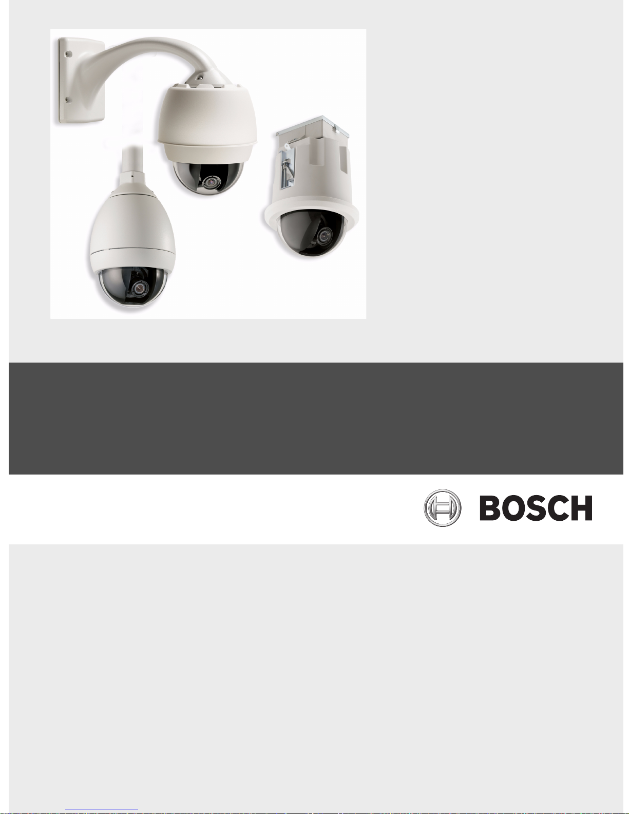
AutoDome Modular Camera System
VG4 200, 300, 500i Series
en VG4-200, VG4-300, VG4-500i Series User’s
Manual


AutoDome Modular Camera System | en iii
Table of Contents
1 Getting Started 1
1.1 Powering On 1
1.2 Establishing AutoDome Control 1
1.2.1 Basic Keyboard Operation 1
1.2.2 Keyboard Commands 2
1.3 Setting the Camera Address 2
1.3.1 FastAddress 2
1.4 Setting Passwords 3
1.4.1 Special Passwords 3
2 On-Screen Display Menu Navigation 5
2.1 Setup Menu 5
2.2 Camera Setup Menu 6
2.3 Lens Setup 8
2.4 PTZ Setup Menu 10
2.5 Display Setup Menu 11
2.6 Communication Setup Menu 13
2.7 Alarm I/O Setup 14
2.8 Rule Setup Menu 16
2.9 Language Menu 17
2.10 Advanced Feature Setup Menu (available with Series 500i only) 18
2.11 Diagnostics Menu 19
3 Common AutoDome User Commands (unlocked) 23
3.1 Setting AutoPan Mode 23
3.2 Setting Preset Shots 23
3.3 Configuring Preposition Tours 23
3.4 Programming the Inactivity Operation 24
3.5 Recorded Tours (300 and 500i Series only) 24
4 Pelco® Protocol Mode 25
4.1 Hardware Configuration 25
4.2 Address Guidelines 25
4.3 Pelco Keyboard Commands 26
4.3.1 Special Preset Commands 26
5 Pelco On-Screen Menus 27
5.1 Setup Menu 27
5.1.1 Command Lock (locked) 28
5.1.2 Bosch Menu (locked) 28
5.1.3 PTZ Setup (unlocked) 29
5.1.4 Other Menus 30
Bosch Security Systems, Inc. VG4-200, VG4-300, VG4-500i Series User’s Manual F01U073308 | 3.0 | 2007.09

iv en | AutoDome Modular Camera System
6 Keyboard Commands by Number 31
7 Advanced Features 35
7.1 Alarm Rules (300 and 500i Series Only) 35
7.2 AutoTrack (500i Series Only) 36
7.3 Virtual Masking (500i Series Only) 37
7.4 Privacy Masking (300 and 500i Series Only) 37
7.5 Motion Detection with Region of Interest (500i Series Only)
(Preset positions 90 through 99) 37
7.6 Image Stabilization (500i Series Only) 38
7.7 Pre-position Tour 38
8 Configuring and Using the IP AutoDome 39
8.1 Overview of Features 39
8.2 System Requirements 40
8.3 Connecting the IP AutoDome to the PC 40
8.4 Configuring the IP Camera 41
8.5 Installing the Required Software 41
8.5.1 Changing the Network Settings 42
8.6 Main Screen 44
8.7 Viewing Live Images and Controlling the AutoDome PTZ 44
8.7.1 Establishing a Connection 45
8.7.2 Configuring Data Streams 45
8.7.3 Controlling Camera Operations 46
8.7.4 Entering a Keyboard Control Command 47
8.8 Alarm Connections 49
8.8.1 Sending an Alarm E-mail 50
8.9 Partitioning 51
8.9.1 Viewing the Partition Status 56
8.9.2 Editing a Partition 57
8.9.3 Deleting Recordings 58
8.9.4 Deleting all Partitions 58
8.10 Recording Scheduler 58
8.10.1 Holidays 60
8.10.2 Deleting Holidays 60
8.10.3 Time Periods 60
8.10.4 Activating the Recording 60
8.10.5 Recording Status 61
8.11 Recording Profiles 61
8.12 Alarm Rules 62
8.12.1 Alarm Rules 62
8.12.2 Alarm Rule Example 63
9 VG4 Audio Connections 67
9.1 Audio Line Input Specifications 67
9.1.1 Wire Specifications 67
9.1.2 Connections 67
9.1.3 Activating Audio Reception 67
F01U073308 | 3.0 | 2007.09 VG4-200, VG4-300, VG4-500i Series User’s Manual Bosch Security Systems, Inc.

AutoDome Modular Camera System | en v
9.1.4 Enabling Audio Transmission 68
9.1.5 Configuring Gain (optional) 69
10 Troubleshooting Guide 71
11 User Command Table 75
Bosch Security Systems, Inc. VG4-200, VG4-300, VG4-500i Series User’s Manual F01U073308 | 3.0 | 2007.09

vi en | AutoDome Modular Camera System
F01U073308 | 3.0 | 2007.09 VG4-200, VG4-300, VG4-500i Series User’s Manual Bosch Security Systems, Inc.

AutoDome Modular Camera System Getting Started | en 1
1 Getting Started
Install and wire the AutoDome according to the Bosch AutoDome Modular Camera System
Installation Manual. A typical system includes a keyboard, matrix switcher, monitor, and
appropriate wiring connections. Please refer to the individual product manuals for complete
installation and setup instructions for each of the system components.
1.1 Powering On
When you turn the AutoDome power on there is a ten (10) second pause before the dome
starts its homing phase. During the homing phase the camera pans left and right and tilts up
and down. It also adjusts the lens focus. The entire homing phase lasts approximately 40
seconds and ends with a splash screen.
1.2 Establishing AutoDome Control
The most common ways to interface with the AutoDome are:
– Using a keyboard and on-screen display (OSD) menus. This method is the most common
and is covered in this manual.
– Using the AutoDome Configuration Tool software running on a PC with Bilinx or the RS-
232/485 communication protocol. Refer to the CTFID User Guide for instructions.
– Using a PC-based graphical user interface (GUI) such as the Bosch DiBos 8 software.
Refer to the DiBos 8 User Guide for instructions.
– Using the Bosch IP Web interface included with the IP Communications Module.
1.2.1 Basic Keyboard Operation
The following tables summarize the basic operations for a standard keyboard and the
functions available to control an AutoDome camera.
Typical Keyboard
Features
Function Keys Selects a specific control setting.
Number Keys Inputs a number from 0 to 9.
Camera Key Selects a camera number.
Enter Key Inputs a selection.
Focus Key Sets the lens focus or makes a menu selection in OSD mode.
Iris Key Sets the lens iris setting or makes a menu selection in OSD mode.
Key LEDs Indicates an active key.
LCD Displays the current status.
Joystick Controls a pan/tilt/zoom (PTZ) AutoDome camera.
Table 1.1 Typical Keyboard Functions
Dome Operation How to control
To Pan Side to Side Move the joystick left or right.
To Tilt Up and Down Move the joystick forward and back.
To Zoom In Twist the joystick clockwise.
To Zoom Out Twist the joystick counterclockwise.
Usage
Table 1.2 Typical Keyboard Controls for an AutoDome Camera
Bosch Security Systems, Inc. VG4-200, VG4-300, VG4-500i Series User’s Manual F01U073308 | 3.0 | 2007.09
2 en | Getting Started AutoDome Modular Camera System
1.2.2 Keyboard Commands
Keyboard control commands are composed of a sequence of three (3) inputs with the
following convention: 1) a Function key + 2) a Command number key(s) + 3) the Enter key.
– Depending on the type of keyboard, the control function keys are labeled:
ON or AUX ON
OFF or AUX OFF
SET or SET SHOT
SHOT or SHOW SHOT
NOTICE! The convention used for control key commands in this manual is ON, OFF, SET, and
SHOT. Refer to your keyboard manual for the key naming conventions.
i
– Command numbers range from 1 to 999. See Chapter 6: Keyboard Commands by Number
for a complete list of keyboard commands.
– The Enter key can also be labeled with the 8 symbol.
For example, the keyboard command to make the AutoDome pan 360º continuously is:
ON-1-ENTER
Press the ON key, then press the number 1 key, and then press ENTER.
1.3 Setting the Camera Address
Once the AutoDome power is turned on and homing is complete, you must set the camera
address. You may also want to assign a password and customize some of the AutoDome
default settings.
NOTICE! You do not need to set a camera address if using Bilinx or Ethernet communication.
See the AutoDome Installation Manual to configure an AutoDome for Bilinx or Ethernet
i
operation.
1.3.1 FastAddress
FastAddress is an AutoDome feature that allows you to set or change a camera address using
the keyboard and on-screen menus.
There are three (3) FastAddress commands:
– ON-999-ENTER: Displays and programs all cameras without an address in the system.
NOTICE! If a keyboard is set to a camera number that already has an address, that camera
also responds to this command.
i
– ON-998-ENTER: Displays and programs all cameras with or without an address in the
system.
– ON-997-ENTER: Displays the current address status of all cameras in the system
simultaneously.
F01U073308 | 3.0 | 2007.09 VG4-200, VG4-300, VG4-500i Series User’s Manual Bosch Security Systems, Inc.

AutoDome Modular Camera System Getting Started | en 3
To set an address to a camera without an address:
1. Select the camera number you want to FastAddress. The system displays the camera
number on the keyboard and the image on the corresponding monitor.
2. Press #-ENTER (where # is the camera number without an address).
3. Press ON-999-ENTER to invoke an on-screen display of cameras on the system without an
address.
4. Follow the on-screen instructions. You receive an on-screen confirmation when the
FastAddress is complete.
To change or clear an address to a camera with an address:
1. Select the camera number you want to FastAddress. The system displays the camera
number on the keyboard and the image on the corresponding monitor.
2. Press #-ENTER (where # is the camera number with an address).
3. Press ON-998-ENTER to invoke an on-screen display of all cameras on the system, with or
without an address.
4. Follow the on screen instructions. You receive an on-screen confirmation when the
FastAddress is complete.
NOTICE! FastAddress is stored in nonvolatile memory and does not change if the power is
turned off or if the default settings are restored.
i
1.4 Setting Passwords
Passwords are used to control access to locked command menus. Unlocked commands are
available to all users. Passwords are four (4) digits in length.
1.4.1 Special Passwords
Password Security Level
0000 (default) Enables security and requires a user to enter the unlock command
OFF-90-ENTER before invoking a locked command.
9999 Disables all security and allows all users to access locked commands.
To set or change a password (locked command):
1. Press OFF-90-ENTER to turn off the command lock.
2. Press SET-802-ENTER to access the password menu.
3. Tilt the joystick up or down to choose a number. Tilt the joystick right to move to the next
number position.
4. Follow the on-screen instructions and save the password. You receive an on-screen
confirmation.
Bosch Security Systems, Inc. VG4-200, VG4-300, VG4-500i Series User’s Manual F01U073308 | 3.0 | 2007.09

4 en | Getting Started AutoDome Modular Camera System
F01U073308 | 3.0 | 2007.09 VG4-200, VG4-300, VG4-500i Series User’s Manual Bosch Security Systems, Inc.
AutoDome Modular Camera System On-Screen Display Menu Navigation | en 5
2 On-Screen Display Menu Navigation
The AutoDome is programmed through the on-screen display (OSD) menus. To access the
OSD menus, you must open the main Setup Menu.
Menus items marked with an * are default settings, unless otherwise noted.
NOTICE! After a period of 4.5 minutes of inactivity, a menu times-out and exits without
warning. Some unsaved settings in the current menu can be lost.
i
2.1 Setup Menu
The main Setup Menu provides access to all programmable AutoDome settings. It is a locked
menu that requires the user to turn off the command lock.
To open the main Setup Menu (locked command):
1. Press OFF-90-ENTER to turn off the command lock.
2. Press ON-46-ENTER to access the Main Menu.
3. Use the joystick to highlight a menu item.
4. Press Focus/Iris to open a menu.
5. Follow the on-screen instructions.
i
NOTICE! The AutoDome displays only those menus applicable to the AutoDome Series
configuration. Use the joystick to navigate through the menu and the Focus/Iris keys to make
a selection.
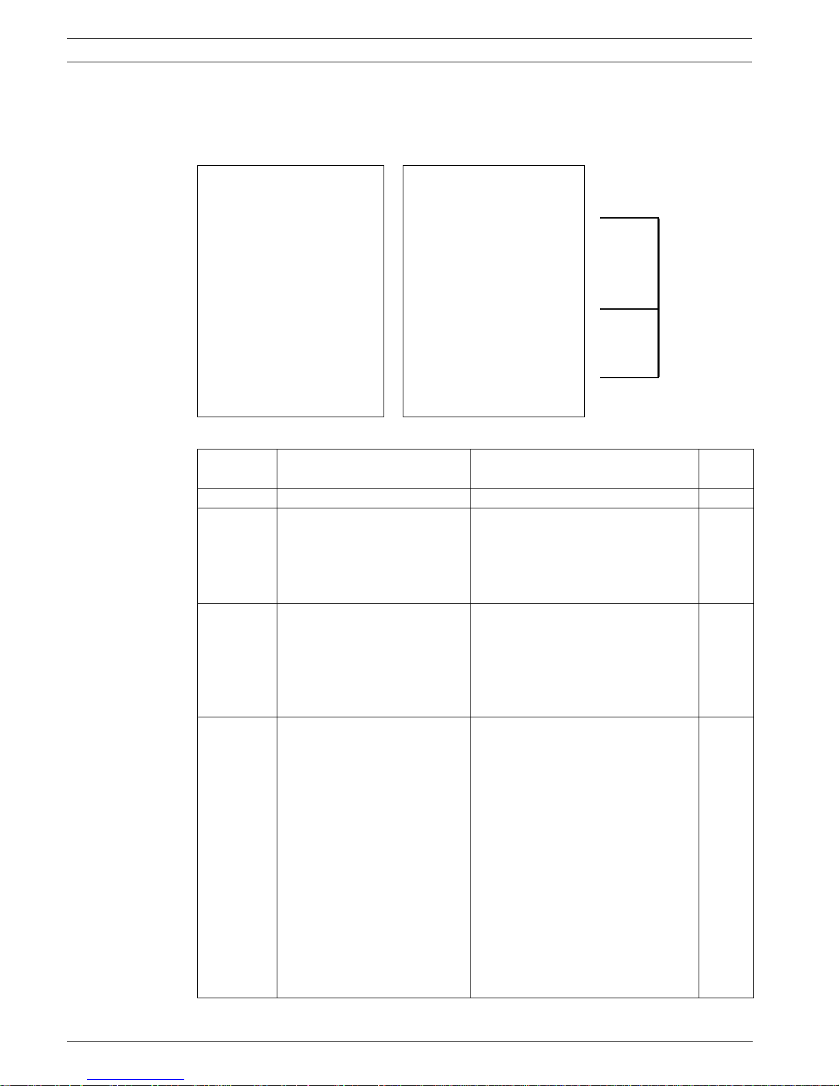
Setup Menu
Exit...
Camera Setup
Lens Setup
PTZ Setup
Display Setup
Communication Setup
Alarm Setup
Language
Advanced
Diagnostics
Focus / Iris: Select
Setup Menu Choices:
Menu Description
Exit Exits the menu.
Camera Setup Accesses adjustable camera settings such as: white balance, gain,
sharpness, sync, line lock, backlight, shutter, and night mode.
Lens Setup Accesses adjustable lens settings such as: focus, iris, zoom speed, and
digital zoom.
PTZ Setup Accesses adjustable pan/tilt/zoom (PTZ) settings such as: Autopan,
tours, PTZ speed, inactivity period, AutoPivot, and tilt limits.
Bosch Security Systems, Inc. VG4-200, VG4-300, VG4-500i Series User’s Manual F01U073308 | 3.0 | 2007.09

6 en | On-Screen Display Menu Navigation AutoDome Modular Camera System
Menu Description
Display Setup Accesses adjustable display settings such as: OSD, sector blanking,
and privacy masking.
Communication
Setup
Alarm Setup Accesses the alarm settings such as: inputs, outputs, and rules (not
Language Displays the language.
Advanced Accesses the advanced features menu including Stabilization,
Diagnostics Displays the status of diagnostic events.
NOTICE! To select the Exit Menu item from anywhere in the current menu, use the Zoom
command.
Accesses communication settings such as: AutoBaud and Bilinx.
available with 200 Series models).
AutoTrack Sensitivity, Camera Height, and Virtual Masking (only
available on 500i Series models).
i
2.2 Camera Setup Menu
The Camera Setup Menu provides access to camera settings that can be changed or
customized. Menu items with an * are the default settings.
Camera Setup
Exit...
*White Bal: EXT ATW
*Gain Control: AUTO
* Max. Gain Level: 6 (4**)
* Sharpness 12
* Synch Mode: Internal
*Line Lock Delay: 0
*Backlight Comp: OFF
*WDR OFF
* Shutter Mode: Auto
SensUP
* Shutter: 1/60
* Auto SensUP Max: 15x
*Night Mode: AUTO
*Night Mode Color: OFF
* Night Mode Threshold: 55
*Pre-Comp 1
Restore Defaults...
* = Factory Setting
** = WDR camera only
Focus / Iris: Select
F01U073308 | 3.0 | 2007.09 VG4-200, VG4-300, VG4-500i Series User’s Manual Bosch Security Systems, Inc.

AutoDome Modular Camera System On-Screen Display Menu Navigation | en 7
Camera Setup Menu Choices:
Menu Description Sub-menu / Description Default
Setting
Exit Exits the menu.
White Balance Maintains proper color
reproduction as the color
temperature of a scene
changes. For example,
from daylight to
fluorescent lighting.
Extended ATW: Adjusts camera
color using extended range.
ATW: Adjusts camera color
constantly.
Indoor W.B.: Optimizes camera
color for typical indoor conditions.
Extended
ATW
Outdoor W.B.: Optimizes camera
color for typical outdoor
conditions.
AWB Hold: Sets the camera's color
settings for the current scene.
Gain Control Electronically brightens
Auto or OFF AUTO
darker scenes which may
cause graininess in low
light scenes.
Max. Gain Level Adjusts the maximum gain
level that the gain control
adjusts to when set to
Sliding scale: – (1 to 6) +
(1=8db, 2=12db, 3=16db, 4=20db,
5=24db, 6=28db)
6
(4 for 36X
camera)
AUTO.
Sharpness Adjusts the sharpness
Sliding scale: – (1 to 16) + 12
level of the picture.
Synch Mode Sets the type of
synchronization mode for
the camera.
INTERNAL: Synchronizes camera to
an internal crystal. This choice is
recommended if there is noise on
INTERNAL
the power line.
LINE LOCK: Synchronizes camera
to AC power. This choice eliminates
picture roll in multi-camera
systems.
Line Lock Delay Optimizes the LINE LOCK
Sliding scale: – (0º to 359º) + 0º
mode to eliminate picture
roll in multiphase power
applications.
Backlight Comp Improves image quality
ON or OFF OFF
when the background
illumination level is high.
WDR Turns the wide dynamic
ON or OFF OFF
range feature on or off.
Shutter Mode: Turns Auto SensUP on or
off.
Shutter Adjusts the electronic
shutter speed (AES).
Auto SensUP or OFF Auto
SensUP
Sliding scale: – (60 at extreme left
to 1/10000) +
1/60 sec.
(NTSC) or
1/50 sec.
(PAL)
Bosch Security Systems, Inc. VG4-200, VG4-300, VG4-500i Series User’s Manual F01U073308 | 3.0 | 2007.09

8 en | On-Screen Display Menu Navigation AutoDome Modular Camera System
Menu Description Sub-menu / Description Default
Setting
Auto SensUP
Max.
Night Mode
(Day/Night
models only)
Night Mode
Color
(Day/Night
models only)
Night Mode
Threshold
(Day/Night
models only)
Pre-Comp
(not applicable
with IP
AutoDome
models)
Restore Defaults Restores all default
Sets the limit for
sensitivity when the
shutter speed is set to
Auto SensUP.
Selects night mode (B/W)
to enhance lighting in low
light scenes.
Determines if color
processing remains in
effect while in night
mode.
Adjusts the level of light
at which the camera
automatically switches
out of night mode (B/W)
operation.
Amplifies the video gain
to compensate for long
distance cable runs.
settings for this menu
only.
15x, 7.5x, 4x, or 2x 15x
ON, OFF, or AUTO AUTO
ON or OFF OFF
Sliding scale: –(10 to 55)+
(in increments of 5)
10 is earlier - 55 is later
Sliding scale: –(1 to 10)+ 1
55
2.3 Lens Setup
The Lens Setup Menu provides access to lens settings that can be changed or customized.
Menu items with an * are the default settings.
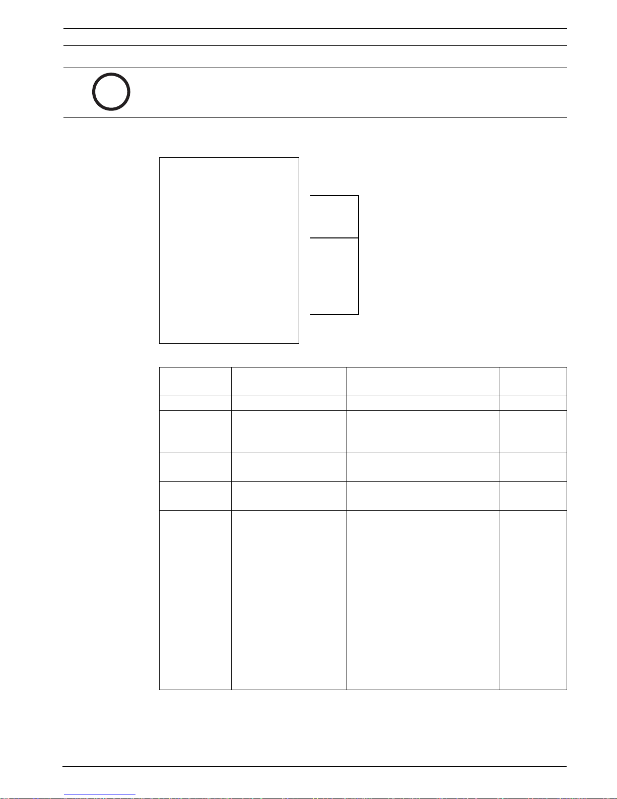
Lens Setup
Exit...
*Auto Focus: SPOT
*Auto Iris: CONSTA
* Auto Iris Level: 8
* Focus Speed: 2
* Iris Speed: 5
*Max Zoom
Speed:
* Digital Zoom: ON
Restore Defaults
* = Factory Setting
Focus / Iris: Select
NT
FAST
F01U073308 | 3.0 | 2007.09 VG4-200, VG4-300, VG4-500i Series User’s Manual Bosch Security Systems, Inc.

AutoDome Modular Camera System On-Screen Display Menu Navigation | en 9
Lens Setup Menu Choices:
Menu Description Sub-menu / Description Default
Setting
Exit Saves and exits the
menu.
Auto Focus Automatically focuses
on the subject in the
center of the screen.
CONSTANT: Auto Focus is always active,
even while the camera is moving.
MANUAL: Auto Focus is inactive; manual
SPOT
focus must be used.
SPOT: The camera activates Auto Focus
after the camera stops movement. Once
focused, Auto Focus is inactive until the
camera moves again.
Auto Iris Automatically adjusts to
varying light conditions.
Auto Iris
Level
Reduces the camera's
iris level for proper
MANUAL: Iris must be adjusted manually.
CONSTANT: Auto Iris is constantly active.
Sliding scale: – (1 to 15) + 8
CONSTAN
T
exposure.
Focus Speed Adjusts the manual
Sliding scale: – (1 to 8) + 2
focus speed.
Iris Speed Adjusts the manual iris
Sliding scale: – (1 to 10) + 5
speed.
Max. Zoom
Speed
Digital Zoom
Adjusts the manual
SLOW, MEDIUM, or FAST FAST
zoom speed.
Enables digital zoom. OFF or ON ON
(not available
with 200
Series
models)
Restore
Defaults
Restores all default
settings for this menu.
Bosch Security Systems, Inc. VG4-200, VG4-300, VG4-500i Series User’s Manual F01U073308 | 3.0 | 2007.09

10 en | On-Screen Display Menu Navigation AutoDome Modular Camera System
2.4 PTZ Setup Menu
The PTZ Menu provides access to pan/tilt/zoom settings that can be changed or customized.
Menu items with an * are the default settings.
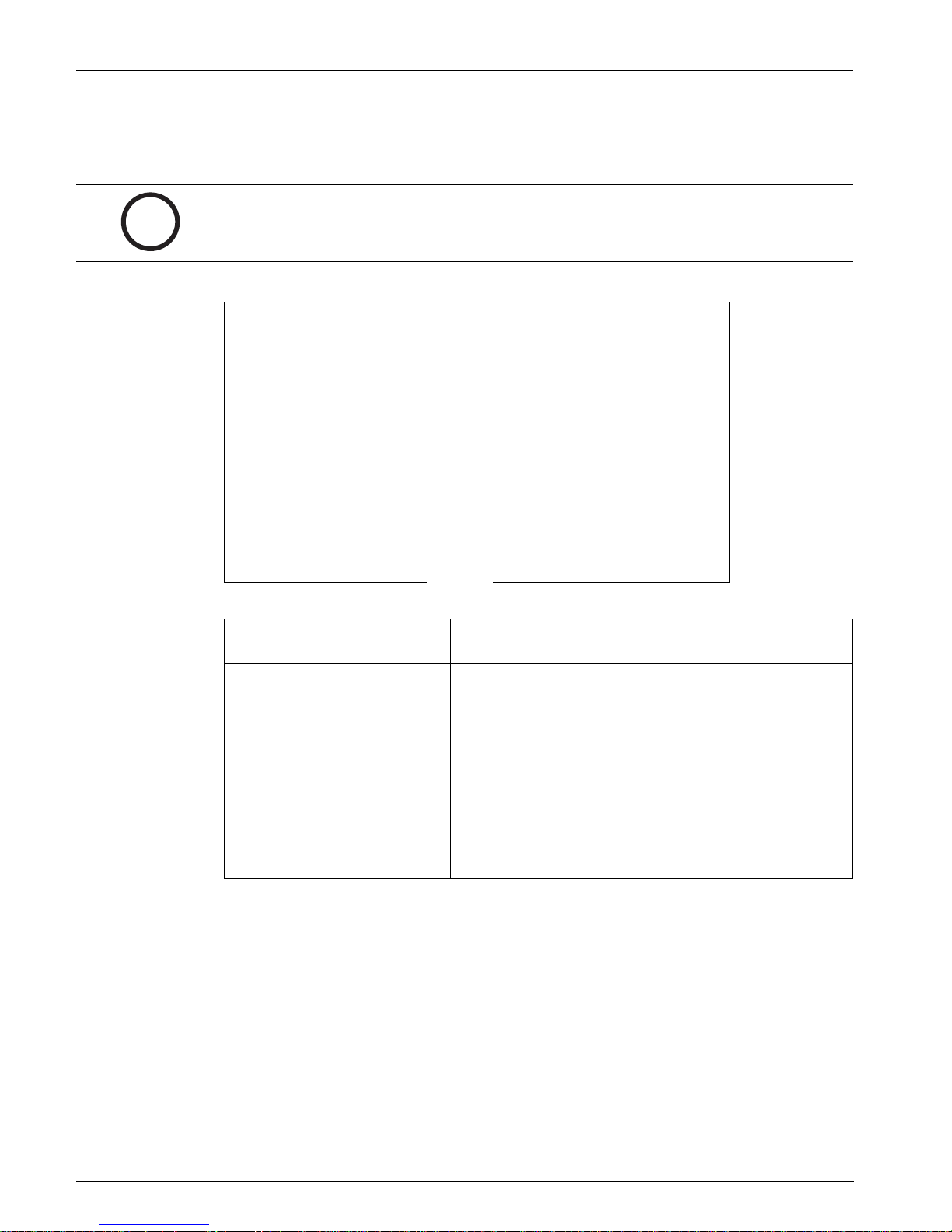
PTZ Setup
Exit...
*Autopan: 30 deg/
sec
* Tour 1 Period: 5 sec
* Tour 2 Period: 5 sec
* PTZ Fixed Speed: 4
*Inactivity: OFF
*Inact. Period 2 min
*AutoPivot: ON
* AutoDome Orientation NORMAL
* Freeze Frame on
Preposition
Tilt Up Limit...
Restore Defaults
ON
* = Factory Setting
Focus / Iris: Select
PTZ Menu Choices:
Menu Description Sub-menu / Description Default
Setting
Exit Exits the menu.
AutoPan Adjusts speed of camera
during AutoPan and
AutoScan.
Tour 1 Period Changes dwell time
between presets during
the tour.
Tour 2 Period
(not available
with 200 Series
models)
PTZ Fixed Speed Sets pan and tilt speed
Inactivity Selects the mode that an
Inactivity Period Sets the time period of
Changes dwell time
between presets during
the tour.
when controlled by a fixed
speed controller.
AutoDome reverts to after
the period of inactivity set
in the inactivity period.
inactivity before the above
action occurs.
Sliding scale: – (1º/sec. to 60º/sec.) +30º/sec.
Sliding scale: – (3 sec. to 10 min.) + 5 sec.
Sliding scale: – (3 sec. to 10 min.) + 5 sec.
Sliding scale: – (1 to 15) + 4
Scene 1: Returns to Preset 1.
Prev Aux: Returns to previous
activity, such as Aux commands 1, 2,
7, 8, 50, or 52.
OFF: Remains on the current scene
indefinitely.
Sliding scale: – (3 sec. to 10 min.) + 2 min.
OFF
F01U073308 | 3.0 | 2007.09 VG4-200, VG4-300, VG4-500i Series User’s Manual Bosch Security Systems, Inc.

AutoDome Modular Camera System On-Screen Display Menu Navigation | en 11
Menu Description Sub-menu / Description Default
Setting
AutoPivot Automatically rotates the
camera 180º when
following a subject
traveling directly beneath
the camera.
AutoDome
Orientation
(not available
with 18x color
camera)
Freeze Frame
On Preposition
(not available
with 18x color
camera)
Tilt Up Limit... Sets the upper tilt limit of
Restore Defaults Restores the default
Automatically rotates the
video 180º.
Holds a preposition video
frame while moving to
another preposition.
the camera.
setting for this menu only.
OFF or ON ON
INVERTED or NORMAL NORMAL
OFF or ON ON
Use joystick to move to a scene
2.5 Display Setup Menu
Provides access to display settings that can be changed or customized. Menu items with an *
are the default settings.
Display Setup
Exit...
*Title OSD: MOMENTARY
* Camera OSD: ON
Display Adjust:
Sector Blanking...
Privacy Masking...
Restore Defaults
* = Factory Setting
Focus / Iris: Select
Bosch Security Systems, Inc. VG4-200, VG4-300, VG4-500i Series User’s Manual F01U073308 | 3.0 | 2007.09

12 en | On-Screen Display Menu Navigation AutoDome Modular Camera System
Display Setup Menu Choices:
Menu Description Sub-menu / Description Default
Setting
Exit Saves and exits the menu.
Title OSD Controls how the OSD
displays sector or shot
titles.
OFF: Titles are hidden.
ON: Titles are displayed continuously.
MOMENTARY: Titles are displayed for a
MOMENTA
RY
few seconds then disappear from the
screen.
Camera
OSD
Controls how the OSD
displays camera response
OFF or ON ON
information, such as
Digital Zoom, Iris open /
close, and Focus near/far.
Display
Adjust
Adjusts the text brightness
and vertical position of the
on-screen title.
Exit: Exits the menu.
Up: Moves screen title up.
Down: Moves screen title down.
Brighter: Brightens the intensity of the
on-screen text.
Darker: Darkens the intensity of the onscreen text.
Sector
Blanking
(not
available
with 200
Allows video blanking of
selected sectors. Available
sectors are 1 through 16.
Follow the on-screen
instructions.
Exit: Exits the menu.
Sector (1-16): Press Focus/Iris to blank
or clear a sector.
Series
models)
Privacy
Masking
(not
available
with 200
Series
models)
Restore
Defaults
Allows masking of
sensitive areas. Up to 24
privacy masks are
available, with a maximum
limit of eight (8) to a
scene.
Restores the default
setting for this menu only.
Exit: Saves and exits menu.
Mask: 1 to 24 masking areas. Follow the
on-screen instructions to set a mask. See
Section 7.4 Privacy Masking (300 and 500i Series
, page 37.
Only)
Restore Defaults: Restores the default
settings for this menu only.
F01U073308 | 3.0 | 2007.09 VG4-200, VG4-300, VG4-500i Series User’s Manual Bosch Security Systems, Inc.
AutoDome Modular Camera System On-Screen Display Menu Navigation | en 13
2.6 Communication Setup Menu
The Communication Setup Menu provides access to baud rate and Bilinx control settings.
Menu items with an * are the default settings.
Communication Setup
Exit...
*AutoBaud: ON
* Baud Rate 9600
* Bilinx: ON
Restore Defaults...
* = Factory Setting
Focus / Iris: Select
Communication Setup Menu Choices:
Menu Description Sub-menu / Description Defaul
t
Setting
Exit Saves and exits the menu.
AutoBaud Turns AutoBaud detection on. Toggles ON or OFF.
ON automatically accepts baud
rates from 2400 to 57600.
(Note: If stepping from 2400 to
57600, you must first set the
controller to 19200 for AutoBaud to
detect the higher baud rate.)
Baud Rate Manually sets the baud rate when
AutoBaud is set to OFF.
Bilinx Turns on Bilinx control
communication,
(Only available when not connected
to a Bilinx data interface unit).
NOTICE! Bilinx protocol is not available on IP cameras.
Choices are 2400, 4800, 9600,
19200, 38400, and 57600. Then
follow the OSD to confirm the
selection.
Toggles ON or OFF. ON
ON
9600
i
Bosch Security Systems, Inc. VG4-200, VG4-300, VG4-500i Series User’s Manual F01U073308 | 3.0 | 2007.09
14 en | On-Screen Display Menu Navigation AutoDome Modular Camera System
2.7 Alarm I/O Setup
The Alarm Setup Menu provides access to the Alarm I/O Setup Menu to establish the alarm
inputs and outputs and to configure alarm rules.
Alarm I/O Setup Inputs Setup
Exit... Exit...
Inputs Setup... 1. Alarm Input 1 N.C.S.
Outputs Setup... 2. Alarm Input 2 N.O.S.
Rule Setup... 3. Alarm Input 3 N.O.
Restore Defaults... 4. Alarm Input 4 N.C.
5. Alarm Input 5 N.O.
6. Alarm Input 6 N.C.
7. Alarm Input 7 N.O.
8. NONE
9. NONE
10. NONE
11. NONE
12. NONE
1-7
Physical
Inputs
8-12
Comman
d Inputs
Focus / Iris: Select Right / Left: Select Mode
Alarm Setup Menu Choices:
Menu Description Sub-menu / Description Default
Exit Saves and exits the menu.
Inputs
Setup
Inputs 1-7 Defines the type of physical
Inputs 8-12 Defines input commands that
Defines physical inputs or
events and commands that can
be used in a rule. There are
twelve (12) alarm inputs
available.
input.
can be used in a rule. Command
inputs can also be customized
by using non-assigned keyboard
command numbers.
Focus / Iris: Select Type
N.O.: Normally open dry contact.
N.C.: Normally closed dry contact.
N.C.S.: Normally closed supervised
contact.
N.O.S.: Normally open supervised
contact.
NONE: No command defined.
Aux On: Responds to a standard or
custom keyboard ON (1-99)
command.
Aux Off: Responds to a standard or
custom keyboard OFF (1-99)
command.
Shot: Responds to a Preset shot or
scene from 1-99. (200 Series 1-64).
AutoTrack: Triggers an alarm when
set to ON. (Available with 500i Series
only).
Motion Detection: Triggers an alarm
when set to ON. (Available with 500i
Series only).
Setting
N.O.
NONE
F01U073308 | 3.0 | 2007.09 VG4-200, VG4-300, VG4-500i Series User’s Manual Bosch Security Systems, Inc.
AutoDome Modular Camera System On-Screen Display Menu Navigation | en 15
NOTICE! Alarm inputs 1 and 2 provide tamper detection, if programmed as supervised, for
breaks or shorts in an alarm circuit. See the AutoDome Modular Camera System Installation
i
Manual for wiring instructions.
Outputs Setup Menu
Outputs Setup...
Exit...
1. Alarm Output 1 N.O. 1-4
2. Alarm Output 2 N.O.
3. Alarm Output 3 N.O. Outputs
4. Alarm Relay N.O.
5. NONE
6. Aux On 1
7. Aux Off 8
8. Shot 99
9. OSD
10. Transmit
11. NONE
12. NONE
Focus / Iris: Select Type
Right / Left: Select Mode
Physical
5-12
Command
Outputs
Outputs Setup Menu Choices
Menu Description Sub-menu / Description Default
Setting
Exit Saves and exits the menu.
Outputs Setup Defines physical outputs
and keyboard commands
for use in a rule.
Outputs 1-3 Defines a physical output. N.O.: Normally open circuit
N.C.: Normally closed circuit
Alarm Relay A fixed output available
for use in a rule.
Outputs 5-12 Defines a command
output for use in a rule.
Aux On: A keyboard ON command.
Aux Off: A keyboard OFF
command.
Shot: Recalls a preset shot.
OSD: An on screen display.
Transmit: Transmits a message
back to the head end (available
with RS-232 serial connections,
Bilinx, and IP AutoDome models).
AutoTrack: Turns AutoTrack on or
off as an output. (Available with
500i Series only).
NONE: No command defined.
N.O.
NONE.
Outputs 5 and
6 set to OSD
and Shot 1
Bosch Security Systems, Inc. VG4-200, VG4-300, VG4-500i Series User’s Manual F01U073308 | 3.0 | 2007.09
16 en | On-Screen Display Menu Navigation AutoDome Modular Camera System
2.8 Rule Setup Menu
The Rule Setup Menu shows the status of the rules and lets you add new rules or modify an
existing rule. The default setting is Empty.
NOTICE! You can program a total of 12 rules. You must define the inputs and outputs before
you program a rule. See Section 2.7 Alarm I/O Setup, page 14 for instructions on configuring
i
alarm inputs and outputs.
Rule Setup... Rule 1
Exit... Exit...
1. Rule 1 Enabled Enabled YES
2. Rule 2 Disabled Input:
3. Rule 3 Invalid Alarm Input 1
4. Rule 4 Empty NONE
5. Rule 5 Empty NONE
6. Rule 6 Empty NONE
7. Rule 7 Empty Output:
8. Rule 8 Empty OSD
9. Rule 9 Empty Shot 2
10. Rule 10 Empty Alarm Relay 2 sec
11. Rule 11 Empty NONE
12. Rule 12 Empty
Focus / Iris: Select Focus / Iris: Select Type
Rule Setup Menu Choices
Menu Description Sub-menu / Description Default
Exit Saves and exits the
menu.
Rule 1-12 Displays the status
of a rule on the right
side of the menu.
There are four (4)
possible rule
statuses.
Selecting a Rule number provides access to its configuration menu. The Rule # Menu allows
you to configure a rule from previously defined alarm inputs and outputs. Once an alarm is
configured with valid inputs and outputs, it can be turned on or off (enabled or disabled)
through its configuration menu.
Right / Left: Select Period Time
Enabled: The rule inputs and outputs are
properly defined and the rule is turned on.
Disabled: The rule inputs and outputs are
defined but the rule is turned off.
Invalid: The rule has a missing or invalid
input or output.
Empty: The rule has no inputs or outputs
defined.
Setting
Empty
F01U073308 | 3.0 | 2007.09 VG4-200, VG4-300, VG4-500i Series User’s Manual Bosch Security Systems, Inc.
AutoDome Modular Camera System On-Screen Display Menu Navigation | en 17
Rule # Choices:
Menu Description Sub-menu / Description Default
Setting
Exit Saves and exits the menu.
Enabled Turns the rule on or off after
its inputs and outputs have
been defined.
Input Toggles through a list of valid
inputs set in the Alarm I/O
Setup > Inputs Setup Menu
that define the rule's inputs. A
rule can have up to four (4)
inputs.
Output Toggles through a list of valid
outputs set in the Alarm I/O
Setup > Outputs Setup Menu
that defines a rule's outputs.
YES to enable or NO to disable NO
Alarm Inputs 1 – 7 and any
additional inputs which were set in
the Inputs Setup Menu, including
Aux On/Off (1-99), Shot, and NONE.
Alarm Outputs 1 – 3 and any
additional outputs set in the
Outputs Setup Menu including:
Alarm Relay, Aux On/Off (1-99),
Shot, OSD, Transmit, and NONE.
Some outputs, such as Alarm
Outputs 1-3, Alarm Relay, and Aux
On/Off can be set to be active for a
specific duration of time as follows:
Seconds: 1-5, 10, 15, or 30
Minutes: 1-5 or 10
Latched: The alarm stays active until
acknowledged.
Follows: The alarm follows the alarm
rule.
NONE
NONE
NOTICE! You can include up to four (4) Input and Output events in a single rule. Each input
and output, however, must be true for the alarm's rule to be valid and enabled.
i
2.9 Language Menu
The Language Menu provides access to a list of languages to display the on-screen menus.
Language
Exit...
English
Spanish
French
German
Portuguese
Polish
Italian
Dutch
Focus / Iris: Save and Exit
Bosch Security Systems, Inc. VG4-200, VG4-300, VG4-500i Series User’s Manual F01U073308 | 3.0 | 2007.09

18 en | On-Screen Display Menu Navigation AutoDome Modular Camera System
Language Menu Choices:
Menu Description Default
Setting
Exit Saves and exits the menu.
Choose a language Select a language in which the system displays the on-
screen menus.
2.10 Advanced Feature Setup Menu (available with Series 500i only)
The Advanced Menu provides access to the Advanced Features Setup menus such as image
Stabilization, AutoTrack Sensitivity and Virtual Masking.
Advanced Feature Setup
Exit...
*Stabilization OFF
* AutoTrack Sensitivity Auto
AutoTrack TImeout OFF
AutoTrack TImeout Period 5 min
* Camera Height: 12
Virtual Masking...
Restore Defaults...
Focus / Iris: Save and Exit
Advanced Feature Setup Menu Choices:
Menu Description Sub-menu / Description Default
Setting
Exit Saves and exits the menu.
Stabilization Turns on video stabilization. OFF
AutoTrack
Sensitivity
AutoTrack
Timeout
AutoTrack
Timeout Period
Sets the sensitivity level of
AutoTrack.
Turns on/off the AutoTrack
Timeout feature.
Enters the AutoTrack Timeout
Period set menu
Sliding scale: -(Auto, 1 to 20)+
Where 1 is more sensitive, and 20
is less sensitive. Auto varies the
sensitivity level based on various
lighting conditions.
When On, AutoTrack will “give up”
after the Timeout Period if tracking
in a confined area, i.e., a tree, flag,
etc.
Sliding scale 30 sec, 1 to 30 min. 5 min
Auto
OFF
F01U073308 | 3.0 | 2007.09 VG4-200, VG4-300, VG4-500i Series User’s Manual Bosch Security Systems, Inc.

AutoDome Modular Camera System On-Screen Display Menu Navigation | en 19
Menu Description Sub-menu / Description Default
Setting
Camera Height Defines the height of the
camera for AutoTrack.
Virtual Masking Enters the Virtual Mask menu.
See Section 7.3 Virtual Masking
(500i Series Only), page 37.
Restore Defaults Restores the default settings
for this menu.
A range from 8 ft (2.4 m) to 100 ft
(30.7m)
Allows up to 24 virtual masks using
five anchor points.
12 ft
(3.6 m)
2.11 Diagnostics Menu
The Diagnostics menu provides access to a list of diagnostic tools and events.
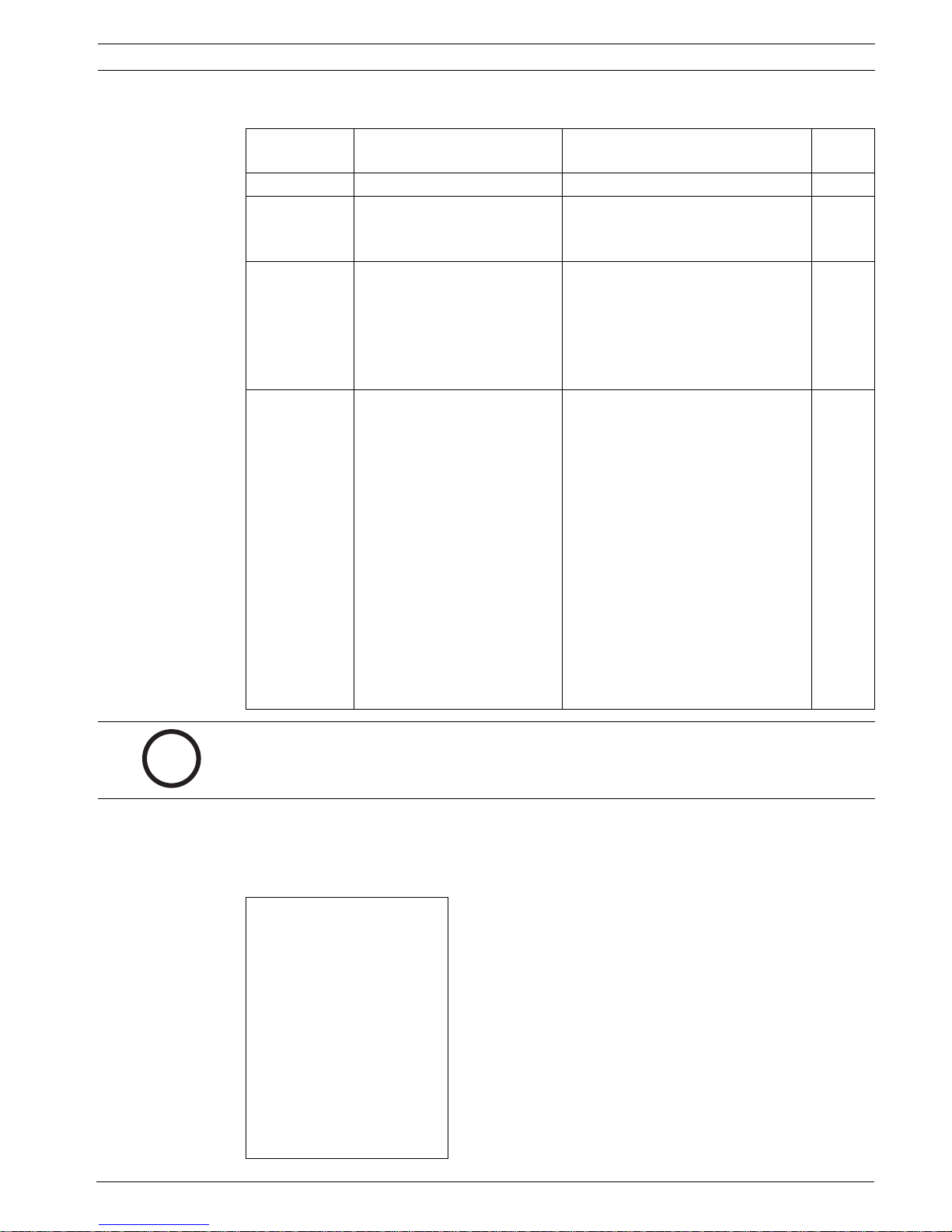
Diagnostics
Exit...
Alarm Status...
BIST...
Internal Temp: Deg F / Deg C
High Temp Events: Deg F / Deg C
Highest Temp Deg F / Deg C
Low Temp Events: Deg F / Deg C
Lowest Temp Deg F / Deg C
Security Access: 0
CTFID Access: 0
Homing Events: 0
Homing Failed: 0
Restart Events: 0
Low Volt Events: 0
Power Up Events: 0
Video Loss Events: 0
Focus / Iris: Save and Exit
Bosch Security Systems, Inc. VG4-200, VG4-300, VG4-500i Series User’s Manual F01U073308 | 3.0 | 2007.09

20 en | On-Screen Display Menu Navigation AutoDome Modular Camera System
Diagnostic Events
Menu Description Sub-menu / Description
Exit Saves and exits the menu.
Alarm Status Enters the Alarm Status menu and
displays the real time status of
Alarm Inputs 1 to 7, Alarm
Outputs 1 to 3, and Alarm Relay
alarm inputs and outputs.
BIST Enters the Perform Built-in Self
Tests menu. If confirmed, the BIST
tests start and the results
displayed.
YES to start test. NO to exit the
menu.
Typical results displayed as
follows:
BIST
Exit...
Data Flash:
PASS
Bilinx:
PASS
FPGA:
PASS
Digital I/O 1:
PASS
Digital I/O2:
PASS
VCA:
PASS
Homing:
PASS
Internal Temp. Displays the current dome
temperature.
High Temp Events Displays the number of times the
high temperature threshold is
exceeded.
Highest Temp Displays the highest temperature
reached.
Low Temp Events Displays the number of times the
low temperature threshold is
exceeded.
Lowest Temp Displays the lowest temperature
reached.
Security Access Displays the number of times the
locked-command menu is
unlocked.
CTFID Access Displays the number of times the
Configuration Tool is accessed.
Homing Events Displays the number of times the
AutoDome was rebooted.
Homing Failed Displays the number of times the
AutoDome failed to home
properly.
F01U073308 | 3.0 | 2007.09 VG4-200, VG4-300, VG4-500i Series User’s Manual Bosch Security Systems, Inc.

AutoDome Modular Camera System On-Screen Display Menu Navigation | en 21
Menu Description Sub-menu / Description
Loss Home Events: Displays the number of times the
AutoDome lost the home position.
Home Position Good Displays if the current AutoDome
home position is good. Displays
YES if good.
Restart Events Displays the number of restart
events.
Low Volt Events Displays the number of times the
AutoDome dropped below the
acceptable voltage limit.
Power Up Events Displays the number of power up
events.
Video Loss Events Displays the number of time that
video was lost.
ExtComm Error
Events:
(IP comm modules
only.)
Displays the number of times that
the IP communications module
lost internal communication with
the System Controller.
Bosch Security Systems, Inc. VG4-200, VG4-300, VG4-500i Series User’s Manual F01U073308 | 3.0 | 2007.09

22 en | On-Screen Display Menu Navigation AutoDome Modular Camera System
F01U073308 | 3.0 | 2007.09 VG4-200, VG4-300, VG4-500i Series User’s Manual Bosch Security Systems, Inc.

AutoDome Modular Camera System Common AutoDome User Commands (unlocked) | en 23
3 Common AutoDome User Commands (unlocked)
This chapter details the commonly used BOSCH keyboard setup commands. See
Section 6 Keyboard Commands by Number, page 31 for a complete list of commands.
3.1 Setting AutoPan Mode
AutoPan mode pans a PTZ camera 360º or pans between user defined limits (when
programmed). The PTZ camera continues to pan until stopped by moving the joystick.
To pan 360º:
1. Press ON-1-ENTER.
2. Move the joystick to stop the pan.
To set left and right pan limits:
1. Move the camera to the starting position and press SET-101-ENTER to set the left limit.
2. Move the camera to the end position and press SET-102-ENTER to set right limit.
To start Auto-pan between limits:
1. Press ON-2-ENTER.
2. Move the joystick to stop the pan.
3.2 Setting Preset Shots
Preset shots are saved camera positions. Shots are saved as scenes, therefore, the terms
SHOT and SCENE are used interchangeably.
To set a Shot:
1. Move the camera to the position you want to save.
2. Press SHOT-#-ENTER where # can be a number from 1 to 99 that identifies the camera
position of the scene. (shots 1-64 for a 200 Series AutoDome.)
To view a Shot:
X Press SHOT-#-ENTER where # is the number of the scene position you want to view.
To store or clear a Shot:
1. Press SET-100-ENTER to access the Store/Clear Scene Menu.
2. Follow the on-screen instructions.
3.3 Configuring Preposition Tours
A Preposition Tour automatically moves the camera through a series of preset or saved shots.
The 200 Series has one (1) standard preset tour available, while the 300 and 500i Series has
two (2) standard preset tours and two (2) customized preset tours. Tour 1 is a standard tour
that moves the camera through a series of shots in the sequence they were set. Tour 2 is a
custom tour that allows you to change the sequence of shots in the tour by inserting and
deleting scenes.
To start Preposition Tour 1: (200, 300, and 500i Series)
1. Set a series of preset shots in the order that you want the AutoDome to cycle through.
2. Press ON-8-ENTER to start the tour. The tour then cycles through the series of shots until
it is stopped.
To stop a Preposition Tour:
X Press OFF-8-ENTER or move the joystick to stop either type of tour.
Bosch Security Systems, Inc. VG4-200, VG4-300, VG4-500i Series User’s Manual F01U073308 | 3.0 | 2007.09

24 en | Common AutoDome User Commands (unlocked) AutoDome Modular Camera System
To add or remove scenes to Preposition Tour 1:
1. Press SHOT-900-ENTER to access the Add/Remove Scenes Menu.
2. Use the Focus/Iris buttons to add or remove the selected scene from the tour.
To start custom Preposition Tour 2: (300 and 500i Series Only)
X Press ON-7-ENTER to start a tour. The tour cycles through the series of shots in the order
they were defined until it is stopped.
To edit a custom Preposition Tour 2:
1. Press SET-900-ENTER to access the Add/Remove Menu.
2. Press the Focus/Iris buttons to add or remove the selected scene.
To change the dwell period of a tour:
1. Press ON-15-ENTER to access the Tour Period Menu.
2. Select the tour (Tour 1 or Tour 2) and follow the on-screen instructions.
3.4 Programming the Inactivity Operation
You can program the AutoDome to automatically change its operating mode after a period of
inactivity.
To access the Inactivity mode (locked command):
1. Press OFF-90-ENTER to turn off the command lock.
2. Press ON-9-ENTER to access the Inactivity Mode Menu.
3. Select one of the following choices:
– Return to Scene 1: Returns the camera position back to the first scene saved in
memory.
– Recall Previous Aux: Returns the camera to the previous operating mode, such as a
Preposition Tour.
3.5 Recorded Tours (300 and 500i Series only)
The 300 and 500i Series AutoDome can make up to two (2) recorded tours. A Recorded Tour
saves all manual camera movements made during the recording, including its rate of pan, tilt
and zoom speeds and other lens setting changes.
To Record Tour A:
1. Press ON-100-ENTER to start recording a tour.
2. Press OFF-100-ENTER to stop recording.
To playback Recorded Tour A:
1. Press ON-50-ENTER to begin continuous playback.
2. Press OFF-50-ENTER or move the joystick to stop playback
To Record Tour B:
1. Press ON-101-ENTER to start recording the tour.
2. Press OFF-101-ENTER to stop the tour.
To playback Recorded Tour B:
1. Press ON-52-ENTER to begin continuous playback.
2. Press OFF-52-ENTER or move the joystick to stop playback.
F01U073308 | 3.0 | 2007.09 VG4-200, VG4-300, VG4-500i Series User’s Manual Bosch Security Systems, Inc.
 Loading...