

Bosch WAQ283S1GB Repair Instruction

R
R
R
E
E
E
P
P
P
A
A
A
I
I
I
R
R
R
I
I
I
N
N
N
S
S
S
T
T
T
R
R
R
U
U
U
C
C
C
T
T
T
I
I
I
O
O
O
N
N
N
S
S
S
F14-D
209_58300000178575_ARA_EN_C.doc – 30.06.2015 Page 1 de 70
1 SAFETY ......................................................... 3
1.1 ESD ........................................................................................ 3
1.2 Qualifications of service technicians ................................. 5
1.3 Identification of danger levels ............................................. 5
1.4 Identification of damage to property .................................. 5
1.5 General safety instructions ................................................. 6
1.6 Purpose of the document .................................................... 8
1.7 General symbols .................................................................. 8
1.8 Safety-relevant symbols ...................................................... 8
2 INSTALLATION ............................................. 9
2.1 Aligning the appliance ......................................................... 9
2.2 Water connection ................................................................. 9
2.3 Electrical connection ......................................................... 10
3 OPERATION ................................................ 11
3.1 Control Panel ...................................................................... 11
3.2 Display ................................................................................ 12
3.3 Acoustic signal ................................................................... 13
3.4 Child Lock ........................................................................... 15
3.5 Reload ................................................................................. 15
4 COMPONENTS ........................................... 16
4.1 Aqua Stop valve (Optional) ............................................... 16
4.2 Aqua Secure valve (Optional) ........................................... 17
4.3 Flow sensor ........................................................................ 18
4.4 Detergent-solution pump ................................................... 19
4.5 Heater................................................................................... 20
4.6 NTC ...................................................................................... 20
4.7 Water level sensor system ................................................. 21
4.8 Door lock ............................................................................. 22
5 FUNCTIONS ................................................. 23
5.1 Motor UMAC / motor actuation .......................................... 23
5.2 Motor BLDC / motor actuation ........................................... 23
5.3 Effectiveness of frequency inverter .................................. 24
5.4 Generation of a sinusoidal voltage ................................... 24
5.5 Motor – functional principle of BLDC................................ 24
5.6 Unbalance detection ........................................................... 25
5.7 Load detection .................................................................... 25
5.8 Foam detection ................................................................... 26
5.9 Door locking feature ........................................................... 27
5.10 Hot water (optional) ............................................................ 28
5.11 Hot water detection (optional) .......................................... 28
5.12 Energy saving ..................................................................... 28
5.13 Aqua-Stop Function............................................................ 29
5.14 Aqua Stop valve Safety System (Optional) ....................... 30
5.15 Heater function ................................................................... 31
5.16 Water level sensor system function .................................. 31
5.17 Flow sensor Function ......................................................... 32
6 REPAIR ........................................................ 33
6.1 Diagnosis / Repair aids ...................................................... 33

209_58300000178575_ARA_EN_C.doc – 30.06.2015 Page 2 de 70
6.2 Removing the top cover .................................................... 34
6.3 Disassemble the rear cover............................................... 34
6.4 Removing the fascia .......................................................... 35
6.5 Removing front panel ........................................................ 36
6.6 Removing the door lock .................................................... 38
6.7 Assembly the door lock ..................................................... 38
6.8 Disassembling Heather and NTC ...................................... 39
6.9 Removing Motor ................................................................. 40
6.10 Removing the inverter module from the bottom ............. 43
6.11 Removing the inverter module from the front side ......... 45
6.12 Removing the drainage pump ........................................... 47
6.13 Removing the Belt pulley: nut 24 or nut 18...................... 49
6.14 Removing Aqua-Stop / solenoid valves (Optional) ......... 52
6.15 Disassembling the cold water valve (optional) ................ 54
6.16 Disassembling Hot and Cold valves ................................. 55
6.17 Removing the drainage hose ............................................ 57
6.18 F14 Flashing of module ..................................................... 59
6.19 I-Service call / select .......................................................... 62
6.20 Possible error images ........................................................ 64
6.21 ................................................................................................... 65
7 FAULT DIAGNOSTICS ............................... 66
7.1 Control unit ......................................................................... 67
7.2 Wrong duration times displayed FD9208-9304 ................ 68
7.3 Heating ................................................................................ 68
7.4 Washing results ................................................................. 69
8 TECHNICAL SPECIFICATIONS .................. 70
209_58300000178575_ARA_EN_C.doc – 30.06.2015 Page 3 de 70
1 SAFETY
1.1 ESD
Term
Electrostatic
Sensitive
Devices
General
State of the art electronics achieve economic efficiency, environmental
protection, user comfort, high functionality and operating safety in
electrical domestic appliances. This high quality technology requires
professional handling and competent specialist knowledge.
All electronic modules are fitted with components which are at risk
from electrostatic voltage.
1.1.1 Components which are at risk
The following components are at risk from electrostatic voltage:
► µ processors and ICs
► Transistors, thyristors and triacs
► Diodes
1.1.2 Causes and effects
You are carrying an electrostatic voltage:
► of up to 35,000 volts if you walk across a non-conductive
carpet,
► of up to 12,000 volts if you walk across a non-conductive PVC
floor,
► of up to 1,800 volts if you are sitting on an upholstered chair.
The electrostatic voltage on your body is transferred to the electronic
components and ESDs you touch which may be damaged as a result.
Shot down!
► A ‘dead’ component
► A ‘dead’ assembly
► A ‘dead’ appliance
Wounded!
► Damaged
► Debilitated
► Early failure

209_58300000178575_ARA_EN_C.doc – 30.06.2015 Page 4 de 70
1.1.3 ESD instructions
All electronic modules and electronic assemblies feature electrostatic
sensitive devices.
The following measures must be taken in order to protect these
electrostatic sensitive devices:
Ensure that the assemblies and modules are appropriately identified.
Before you touch and measure the ESDs, put on an electrostatic
protection system (wrist band with earthing module).
Avoid touching ESDs with chargeable plastics (film, etc.).
When taking hold of assemblies, modules and printed circuit boards,
try not to touch the printed conductors or connections.
Keep ESDs away from monitors and television sets.
Only use conductive materials or the original packaging for
transportation.
1.1.4 Electrostatic protection system
The electrostatic voltage of the body is discharged via the wrist band
and the earthing module.
For reasons of safety this does not occur directly, but via a combination of resistors.
The earthing or protective conductor connection must not be
damaged!
209_58300000178575_ARA_EN_C.doc – 30.06.2015 Page 5 de 70
1.2 Qualifications of service technicians
The described activities may be carried out only by electrical engineers
and electrical engineers for specific activities if they have been trained
by BSH or an authorised establishment.
An electrical engineer is one who, on account of his specialist training,
knowledge and experience as well as his knowledge of the relevant
regulations, can asses the work assigned to him and identify potential
hazards.
An electrical enginner for specific activities is a person who is instructed and, if required, trained by an electrical engineer on the work
assigned to him and the potential hazards of improper behaviour and
who was instructed on the required protective devices and protective
measures.
Observe country-specific regulations.
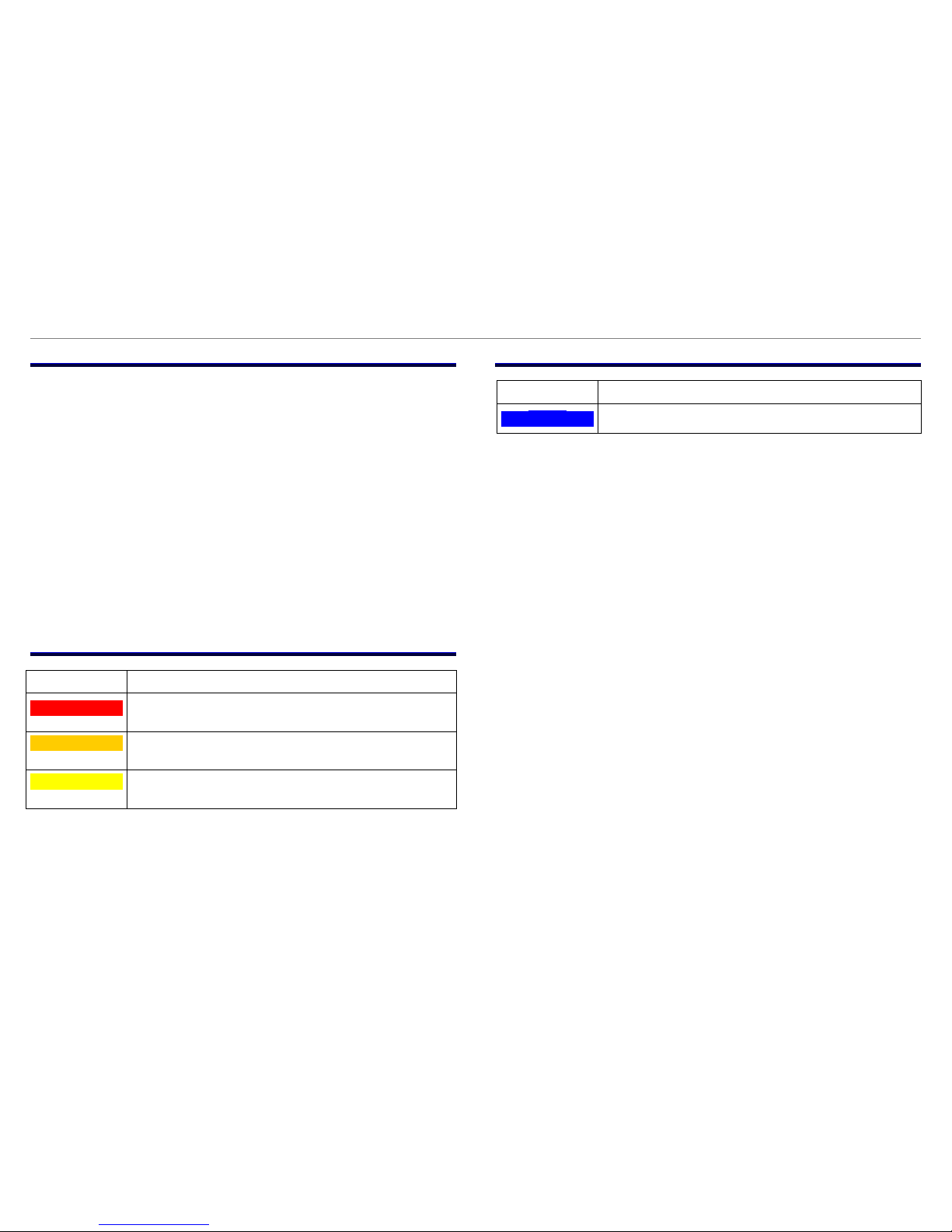
1.3 Identification of danger levels
Identification
Meaning
DANGER
Imminent danger which may result in death or
serious injury if it is not avoided.
WARNING
Potentially imminent danger which may result in
death or serious injury if it is not avoided.
CAUTION
Potentially imminent danger which may result in minor
injury or damage to property if it is not avoided
.
1.4 Identification of damage to property
Identification
Meaning
NOTE
Warning of potential damage to property
209_58300000178575_ARA_EN_C.doc – 30.06.2015 Page 6 de 70
1.5 General safety instructions
► Read repair manual and follow the instructions included in it.
► Proceed systematically and follow the instructions for
troubleshooting and repairs.
► When repairs are complete, check the effectiveness of the protect-
tive measures in accordance with VDE 0701 or the corresponding
country-specific regulations and perform a function test.
If the test is not passed, clearly identify the appliance as not safe
and inform the operator in writing.
The test for the effectiveness of the protective measures must be
documented in a suitable manner. It is recommended to write
down the measured values.
► Use only conductors which comply with the currently valid health
and safety regulations at work.
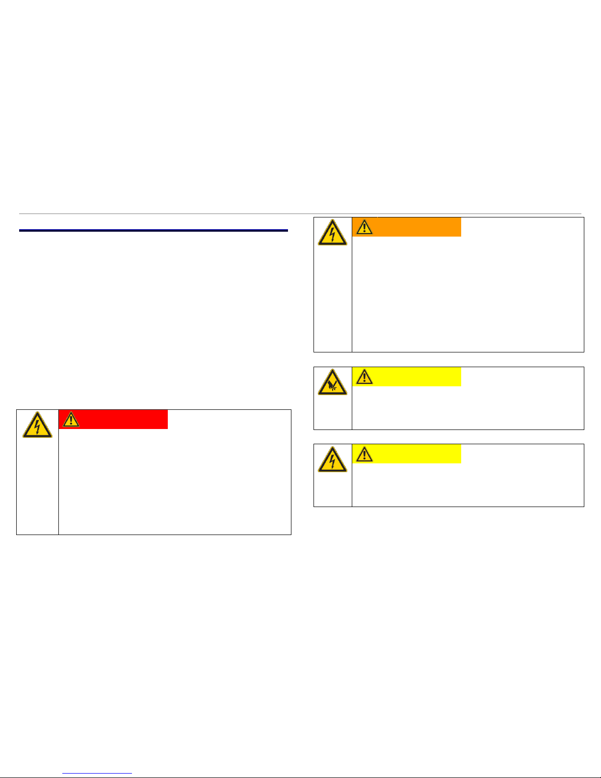
DANGER
Exposed live parts
Danger to life caused by electric shock!
► Disconnect the appliance from the power supply.
► Do not touch housing, frame or components.
► Use residual-current-operated circuit-breaker if tests
have to be conducted while the appliance is live.
► Ensure that the resistance of the protective conductor
does not exceed the standardised values.
WARNING
Exposed conductive parts may be live if a fault has
occurred.
Danger to life caused by electric shock!
► Disconnect the appliance from the power supply.
► Do not touch housing, frame or components.
► Use residual-current-operated circuit-breaker if tests
have to be conducted while the appliance is live.
► Ensure that the resistance of the protetive conductor
does not exceed the standardised values.
CAUTION
Risk of being cut on sharp edges.
► Wear protective gloves.
► Wear personal protective equipment.
CAUTION
Charged capacitors
Risk of injury from electric shock and startle response.
► Discharge capacitors before working on the appliance.

209_58300000178575_ARA_EN_C.doc – 30.06.2015 Page 7 de 70
NOTE
Components which come into contact with electrostatic voltage will be damaged beyond repair
► Before carrying out any work, apply protective system
to components susceptible to electrical discharge.
► Observe measures to protect the components suscep-
tible to electrical discharge.
NOTE
Components which are replaced haphazardly will be
damaged beyond repair
► Before replacing components, perform
troubleshooting.
► Check systematically.
► Observe Technical Documentation.
► Do not replace components without reason.
209_58300000178575_ARA_EN_C.doc – 30.06.2015 Page 8 de 70
1.6 Purpose of the document
The repair instructions:
► guide the service technician in troubleshooting and repairing
domestic appliances
► assist the technical storeman in deciding which spare parts are
probably required for the repair
► inform trainers and technical personnel about design, function,
troubleshooting and repairs
► as supporting documentation support the training of the technical
personnel
Apart from the repair instructions the service technician uses the
following documents:
► Parts list
► Exploded drawing
► Circuit diagrams
The described troubleshooting and repair may be carried out a service
technician only.
These repair instructions are assigned to specific appliances and are
valid for those appliances only.
1.7 General symbols
Symbol
Meaning
Special information
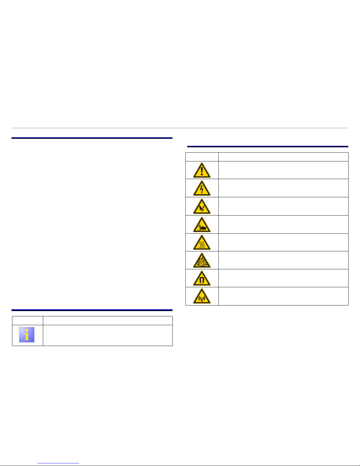
1.8 Safety-relevant symbols
Symbol
Meaning
General warning information
Danger of electric shock
Risk of being cut
Risk of crushing
Hot surfaces
Risk of explosion
Strong magnetic field
Non-ionising radiation
209_58300000178575_ARA_EN_C.doc – 30.06.2015 Page 9 de 70
2 INSTALLATION
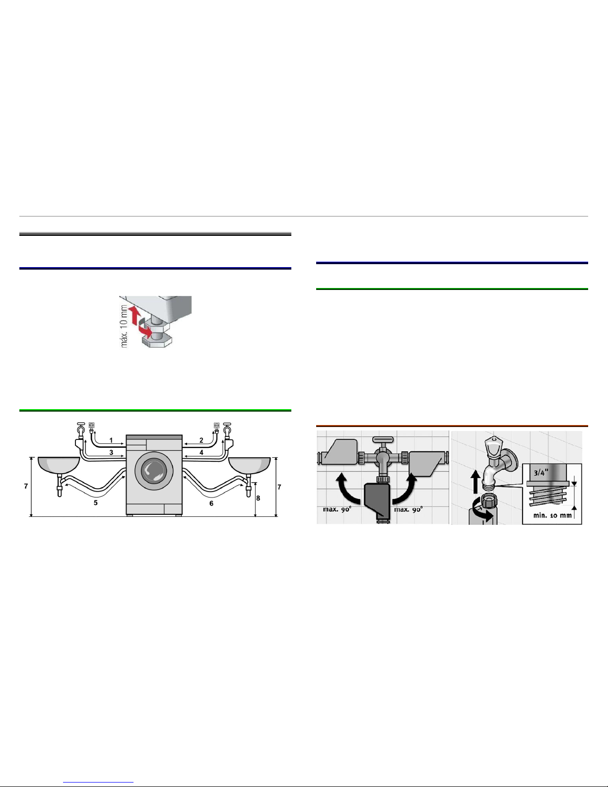
2.1 Aligning the appliance
To ensure fault-free operation, the appliance must be aligned
precisely via the height-adjustable feet.
These feet allow adjusting its height 10 mm.
If the appliance is installed on a base, the appliance must be attached
with the attachment kit, mat. no. 493529 for reasons of safety.
2.1.1 Hose and electric cable lengths
1
aprox. 100 cm
5
aprox. 90 cm
2
aprox. 145 cm
6
aprox. 135 cm
3
aprox. 145 cm
7
max. 100 cm
4
aprox. 100 cm
8
min. 60 cm
If appliances feature Aqua Stop, the supply hose can be extended by
250 cm with the Aqua Stop extension (available from customer service
Mat No. 350564).
2.2 Water connection
2.2.1 Water supply
The water connection (3/4 inch) requires a conventional water line
with a water pressure of at least 1 bar (1 at.)
The optimum water pressure in the supply network is between 2 and
10 bar.
When the tap is on, the water flow must be at least 10 l/min
If the water pressure is between 1 and 2 bar (6 l/min), the
consumption parameters cannot be assure.
If the water pressure is more than 10 bar (10 at.), a pressure reducing
valve must be installed.
2.2.1.1 Aqua Stop or Aqua Secure version (optional)
The Aqua-Stop must be installed as shown in the picture
209_58300000178575_ARA_EN_C.doc – 30.06.2015 Page 10 de 70
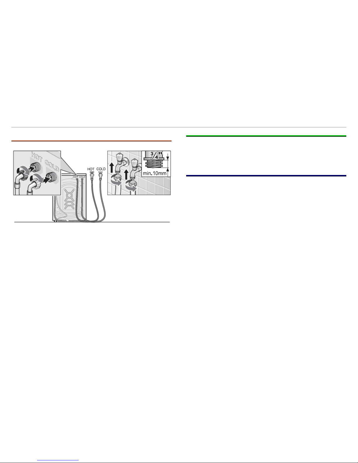
2.2.1.2 Hot Water appliances (optional)
The appliances with hot water connection have an additional water
valve.
The hot water connection is in red and can be installed to water
supply with maximum temperature of 60ºC.
If there is no hot water supply, it is not necessary to connect the hot
water hose or closet he water valve with a cover.
2.2.2 Water outlet
The waste water hose may be extended to 4 m (432060 2, 20 m), but
only if the hose is lying flat on the floor and has no more than one
connection.
2.3 Electrical connection
Connect the appliance to a correctly installed earthed socket only.
Comply with the specifications on the rating plate.
Fuse: 10 A

209_58300000178575_ARA_EN_C.doc – 30.06.2015 Page 11 de 70
3 OPERATION
3.1 Control Panel
1
Optimisation buttons
2
Spin speed selection
3
Display
4
“Ready in..” button
5
Programme selector
6
Start Reload button
7
Status LED´s
8
Spin Speed LED´s
3.1.1 Programme selector (5)
The programme selector with combined main switch has 16 positions.
Special programmes, cottons/ coloureds programmes, easy-care
programmes, delicates programmes, mix programmes and woollens
programmes can be selected.
3.1.2 Optimisation buttons (1)
The additional buttons are only optionally available depending on the
appliance model!
There is more information in the instruction book of the appliance.
3.1.2.1 TurboPerfect/ SpeedPerfect
For washing in a shorter time (60% reduction) with a washing outcome
comparable to that of the standard programme.
3.1.2.2 EcoPerfect
Saves energy (20% reduction) with a washing performance
comparable to that of the standard programme.
3.1.2.3 Reduced Ironing
Special spin sequence with subsequent fluffing. Gentle final spin:
residual moisture in
3.1.2.4 Water Plus
Increases the water level and performs an additional rinse cycle,
extended washing time. For areas with very soft water or for further
enhancing the spin result.
209_58300000178575_ARA_EN_C.doc – 30.06.2015 Page 12 de 70
3.1.2.5 Skin care
Performs an additional rinse cycle.
3.1.3 Start / Reload (6)
With this button it is possible to start the programme or to
subsequently load additional laundry, and to activate/deactivate the
childproof lock.
When it is pressed, if it is possible to reload, the display will show the
message “YES” or the door symbol will be activated.
3.1.4 Ready in (4)
When you select the programme, the relevant programme duration is
displayed. You can delay the end of the programme before it begins.
The ready in-time can be set in increments of one hour up to a
maximum of 24 hours.
Press the (Ready in) button until the required number of hours is
displayed (h = hour). Choose Start/Reload.
3.1.5 Spin speed button (rpm) (2)
Button used for the selection of spin speed for the washing program.
The maximum speed depends on the selected program.
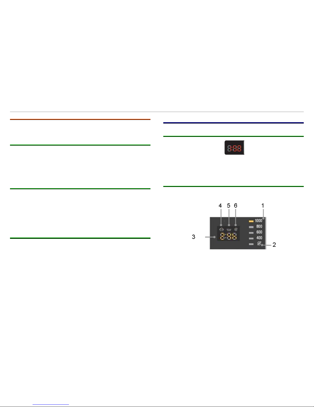
3.2 Display
3.2.1 Bosch
The Bosch display shows the following information: program duration,
end delay selection. When the child lock is activated, it shows the
message CL.
3.2.2 Siemens
The symbol display shows the program status, foam detection, spin
speed, end delay and child lock (CL).
1
Spin speed
4
Foam detection
2
FLOT
5
Rinse
3
Time display
6
spin
209_58300000178575_ARA_EN_C.doc – 30.06.2015 Page 13 de 70
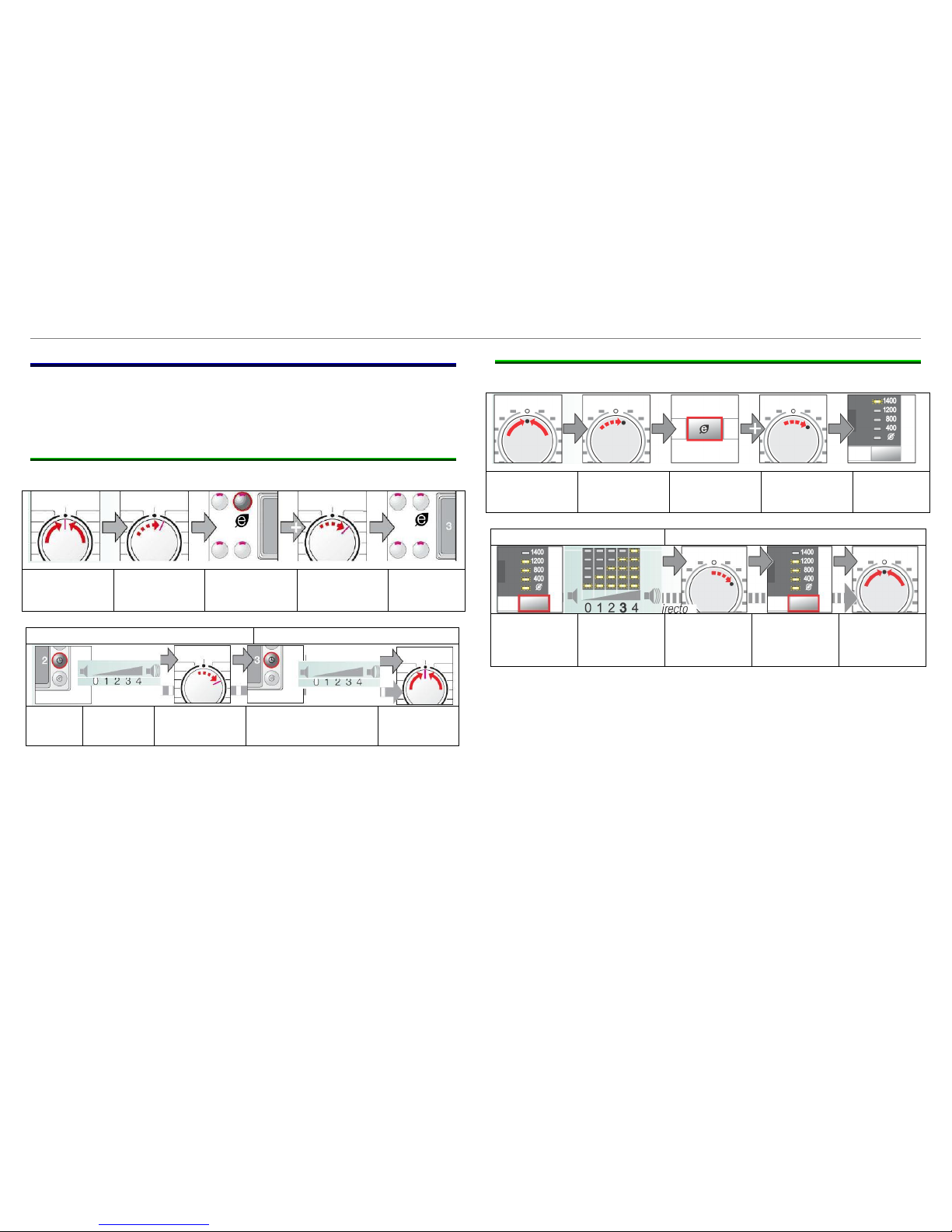
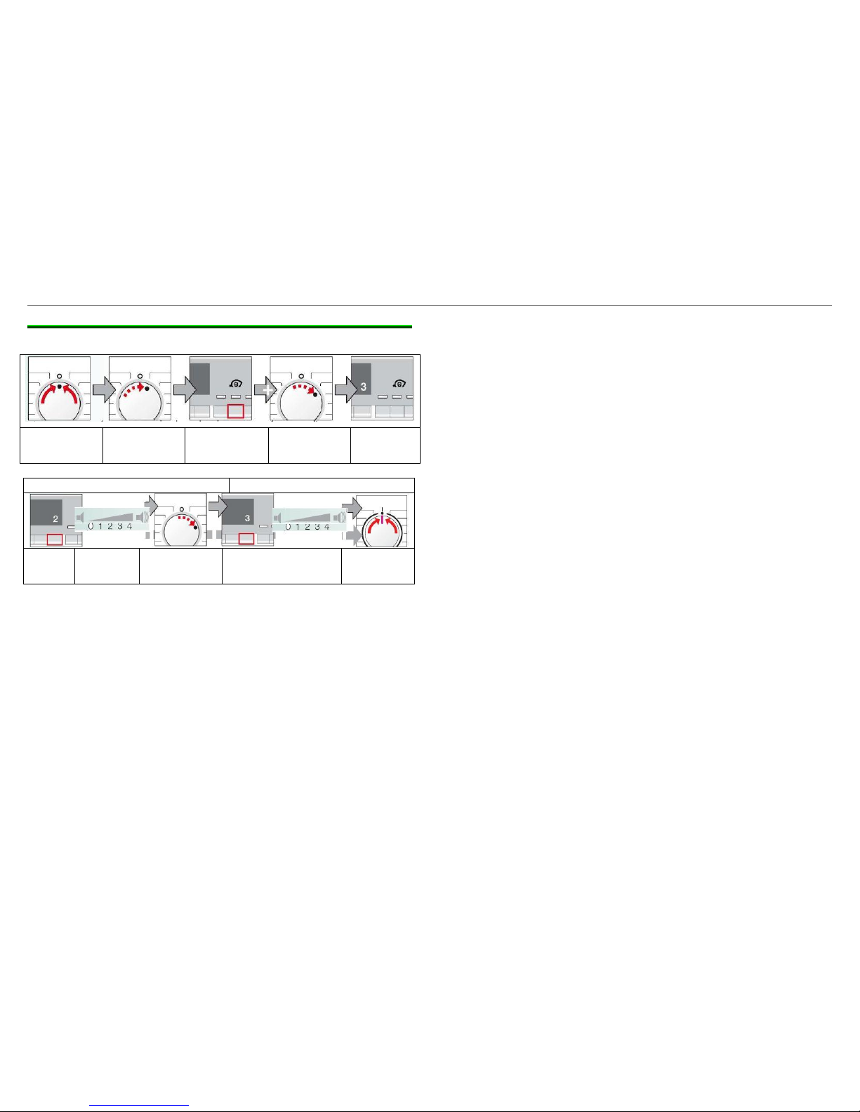
3.3 Acoustic signal
The signal can be switched on and off. The signal can be switched off
or set to a different volume before the programme starts and at the
end of the programme.
3.3.1 Setting the signal volume (Bosch)
Set to 0
Turn the
selector 1
position
Press and hold
Turn the
selector 1
position
Release the
button
Button signals
Information signals
Press
the
button
Select the
volume
Turn the
selector 1
position
Press the button to
select the volume
Set to 0
3.3.2 Setting the signal volume (Siemens):
Set to 0
Turn the
selector 1
position
Press and hold
Turn the
selector 1
position
Release the
button
Button signals
Information signals
Press the
button
Select the
volume
Turn the
selector 1
position
Press the
button to
select the
volume
Set to 0
209_58300000178575_ARA_EN_C.doc – 30.06.2015 Page 14 de 70
3.3.3 Setting the signal volume (Balay)
Press the
button
Select the
volume
Turn the
selector 1
position
Press the
button to select
the volume
Set to 0
Button signals
Information signals
Press
the
button
Select the
volume
Turn the
selector 1
position
Press the button to
select the volume
Set to 0

209_58300000178575_ARA_EN_C.doc – 30.06.2015 Page 15 de 70
3.4 Child Lock
The appliance can be locked to prevent the set functions from being
changed inadvertently.
3.4.1 Activation
After the start/end of the programme, press the Start/Reload button for
five seconds.
The child lock remains activated after the end of the washing program
and appliance disconnection.
Before starting a new program, the child lock must be deactivated.
3.4.2 Deactivation
With the program selector in the same position as for activation, press
the Start/Reload button for 5 seconds, until the child lock symbol
disappears.
The child lock symbol remains on in the activation program and
flushes in the other programs.
3.5 Reload
Press Start/Reload to add additional items of laundry after the
programme has started. The machine checks whether reloading is
possible.
The display shows different messages depending on the result of the
checking:
YES: reloading is possible.
NO flashes: wait until YES lights.
NO: it is not possible to reload.
Note: for safety reasons, the washing machine door remains locked
when the water level and/or temperature is high, or during spinning.
To continue the programme, press the Start/Reload button.
209_58300000178575_ARA_EN_C.doc – 30.06.2015 Page 16 de 70
4 COMPONENTS
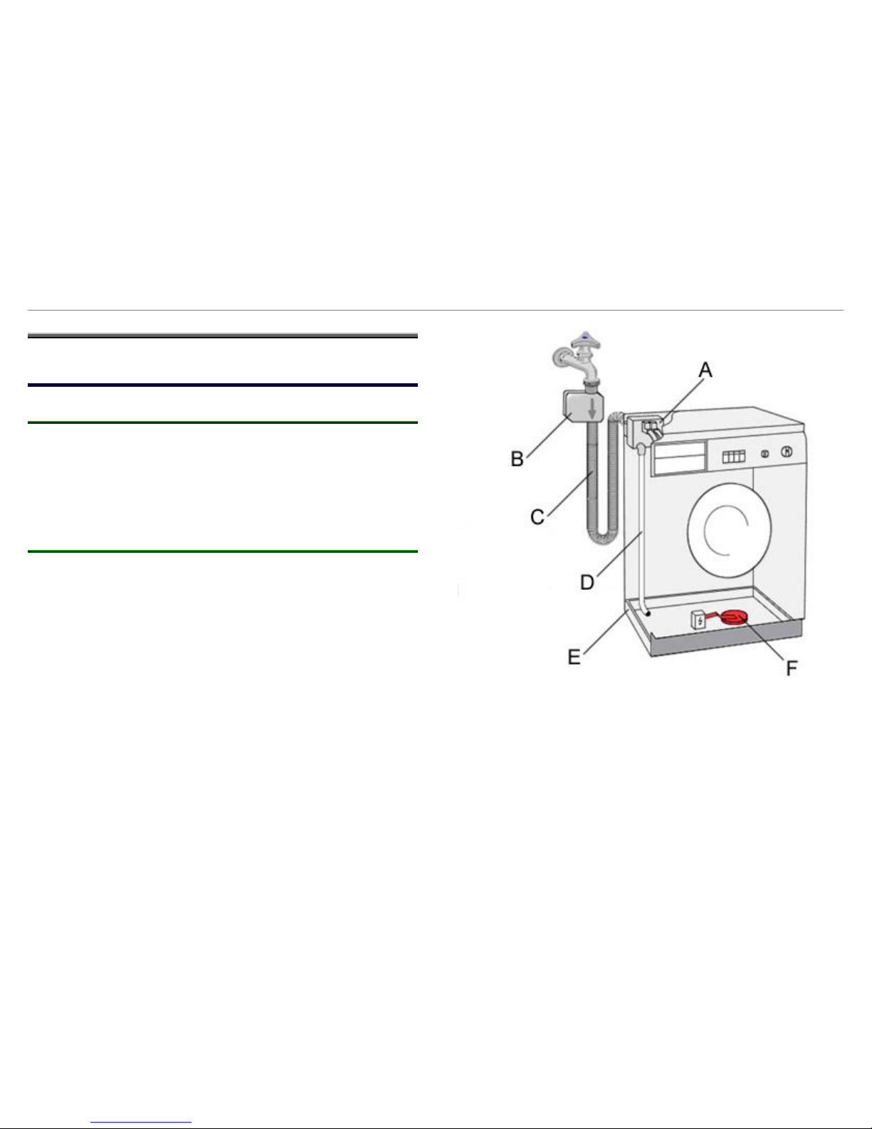
4.1 Aqua Stop valve (Optional)
4.1.1 Function:
An electric solenoid valve which is enclosed by a housing is attached
to the tap. The housing is connected to the appliance with a double
supply hose. The double supply hose contains the water supply hose
and electric control cable for the solenoid valve. The safety function is
actuated via the float in the base pan. The water flow is then stopped
mechanically.
4.1.2 Technical specifications:
► Nominal voltage 230–240 V
► Frequency 50 Hz
► Resistance 4.13 k ± 10 %
► Flow rate 10 l/min ± 10%
► Water pressure 1.0–10 bar
► Water inlet temperature max. max. 25 °C
A
Equipment valve
B
Aqua-stop
C
Double inlet hose
D
Leakage water hose
E
Drip tray
F
Soil float
209_58300000178575_ARA_EN_C.doc – 30.06.2015 Page 17 de 70
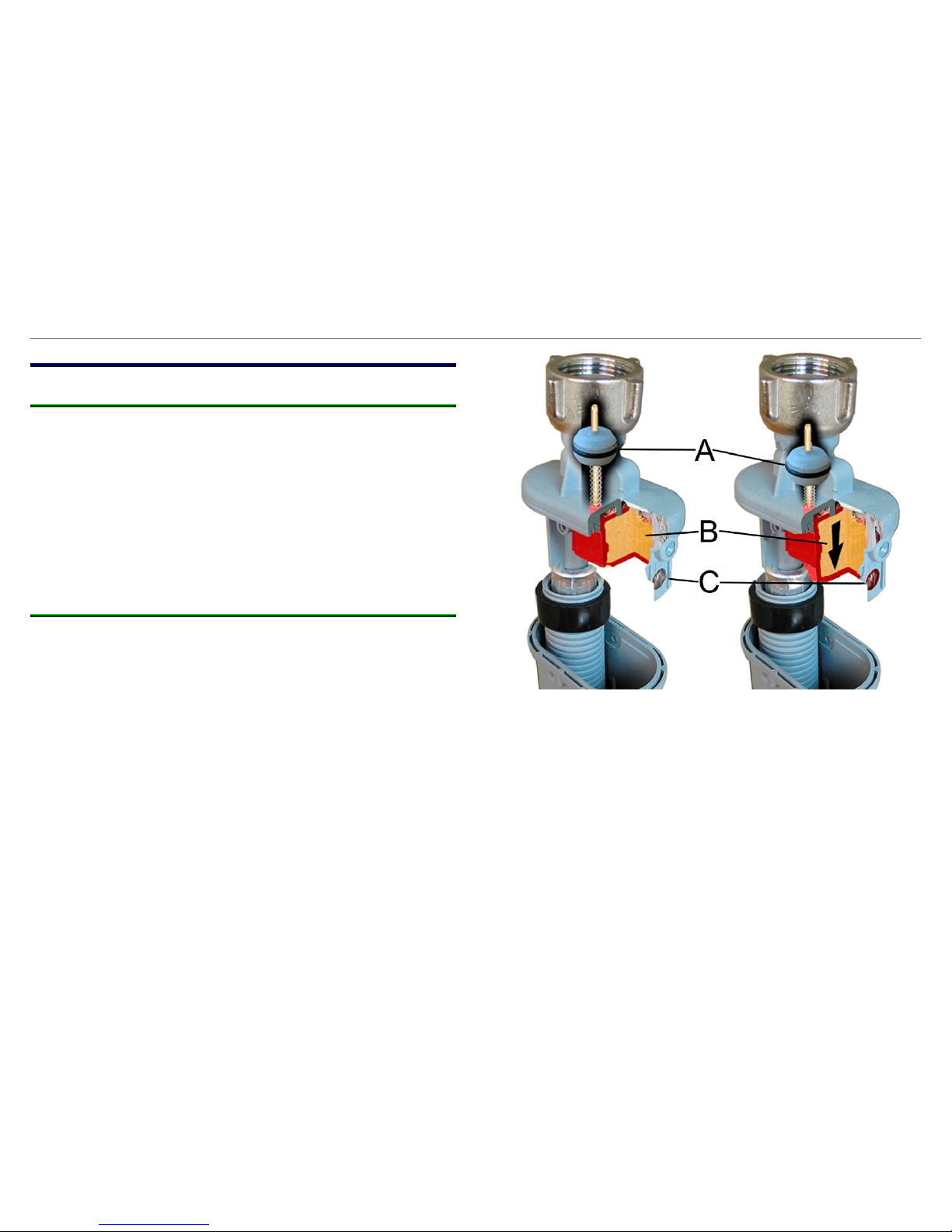
4.2 Aqua Secure valve (Optional)
4.2.1 Function:
A mechanical valve which is enclosed by the Aquastop housing is
attached to the tap. The housing is connected to the appliance with a
double supply hose. If the inner hose leaks, the water flows through
the double supply hose into the Aquastop housing. The safety function
is actuated mechanically; a sponge expands which pulls down a
plunger and closes the valve. The inspection window on the Aquastop
housing turns red. The Aquastop hose must be replaced because the
sponge does not contract when it dries.
In addition, the appliance has a float in the base pan; this float stops
the water inflow if there is a leak in the appliance.
4.2.2 Technical specifications:
► Flow rate 0.5–20 l/min
► Water pressure 0.2–10 bar
► Water supply temperature 5–93 °C
► Air temperature 5–60 °C
► Air humidity 30–95 %
Not actuated
Actuated
A
Plunger
B
Sponge
C
Inspection window
209_58300000178575_ARA_EN_C.doc – 30.06.2015 Page 18 de 70
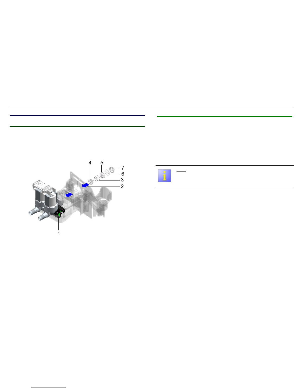
4.3 Flow sensor
4.3.1 Function
The flow sensor seizes the quantity of water, directly before the
valves. It consists of an impeller with a magnet core and a one
resounds - to hall- IC. The impeller is shifted as a function of the water
flow in turn. In the case of turn of the impeller by the magnet of
impulses to resound - to hall-IC given.
1
Hall-IC
5
nozzle
2
Flow direction
6
limiter
3
Impeller wiht a
magnet
7
Filter
4
Impeller holder
4.3.2 Datos técnicos
► Operational voltage: 12 V (3,8 V – 24 V)
► Rate of flow: 2 - 10 l/min
► Flow max.: 10 l/min
Note:
With bubbles can higher flow rates can be recognized
209_58300000178575_ARA_EN_C.doc – 30.06.2015 Page 19 de 70
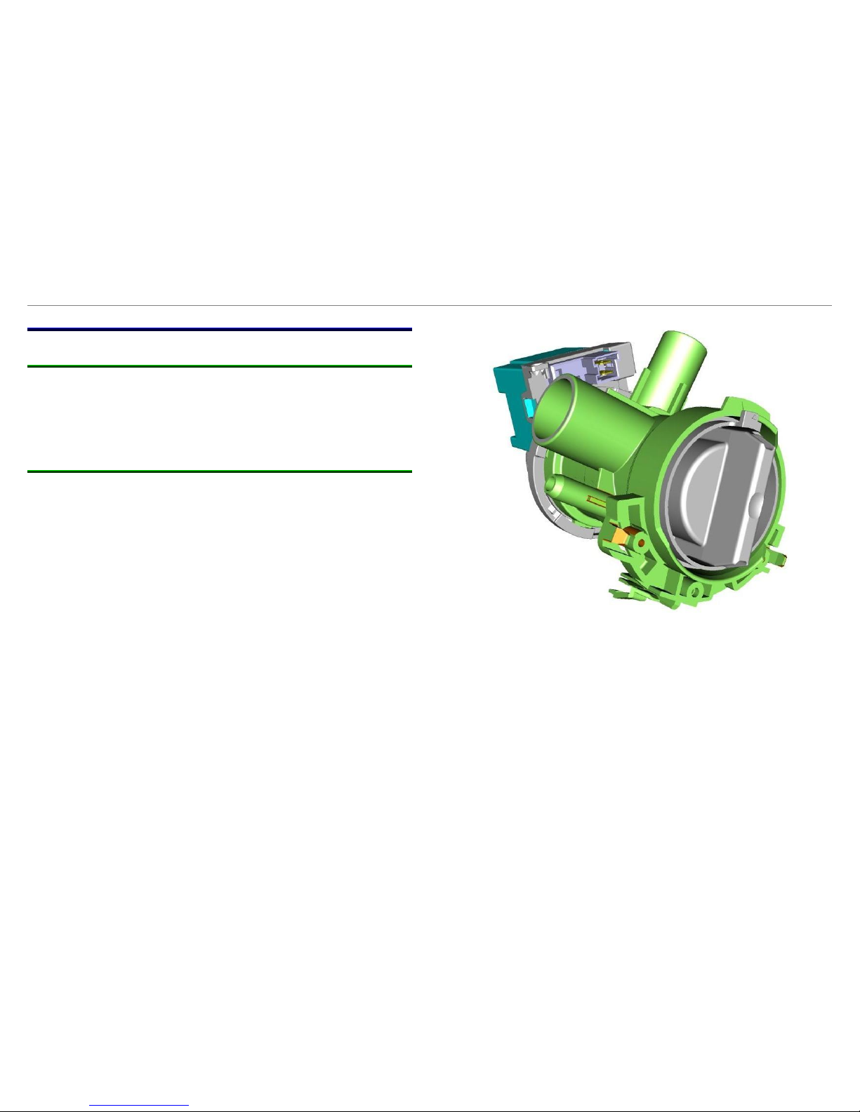
4.4 Detergent-solution pump
4.4.1 Function:
The pump is actuated by a relay.
The detergent-solution pump features a thermal protection device.
The thermal protection device is actuated when the power input is too
high.
4.4.2 Technical specifications:
► Nominal voltage 230 VAC / 50 Hz
► Delivery head 1.0 m
► Delivery rate 18 l/min
► Resistance 155Ω ±7%
► Power 30 W
209_58300000178575_ARA_EN_C.doc – 30.06.2015 Page 20 de 70
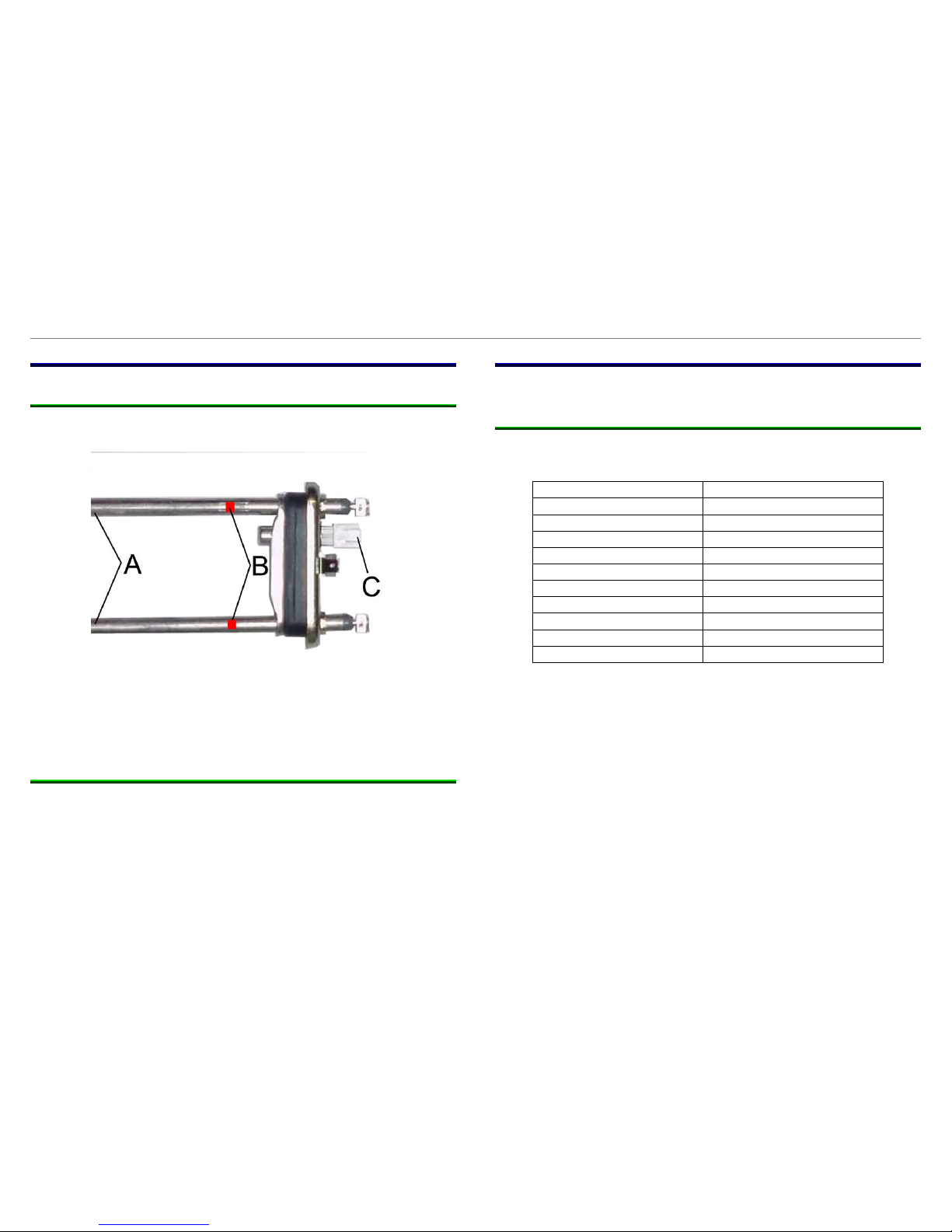
4.5 Heater
4.5.1 Function:
The heating element A has two integrated fuses B (boil-dry
protection). The fuses cannot be changed.
A
Heating elements
B
Integrated fuses
C
NTC (resistance with negative temperature coefficient)
4.5.2 Technical data:
► Nominal power 2000 W +5% / -5%
► Resistance see connection diagram
4.6 NTC
The NTC measures constantly the water temperature.
4.6.1 Technical data:
Operating range: from –5 °C to 103 °C
Temperature in °C
Resistance in kΩ
10
9,2 - 10,0
20
5,8 – 6,2
25
4,7 – 5,0
30
3,8 – 4,0
40
2,5 - 2,6
50
1,69 – 1,78
60
1,18 – 1,22
70
8,28 – 8,69
80
0,69 – 0,74
90
0,43 – 0,46
209_58300000178575_ARA_EN_C.doc – 30.06.2015 Page 21 de 70
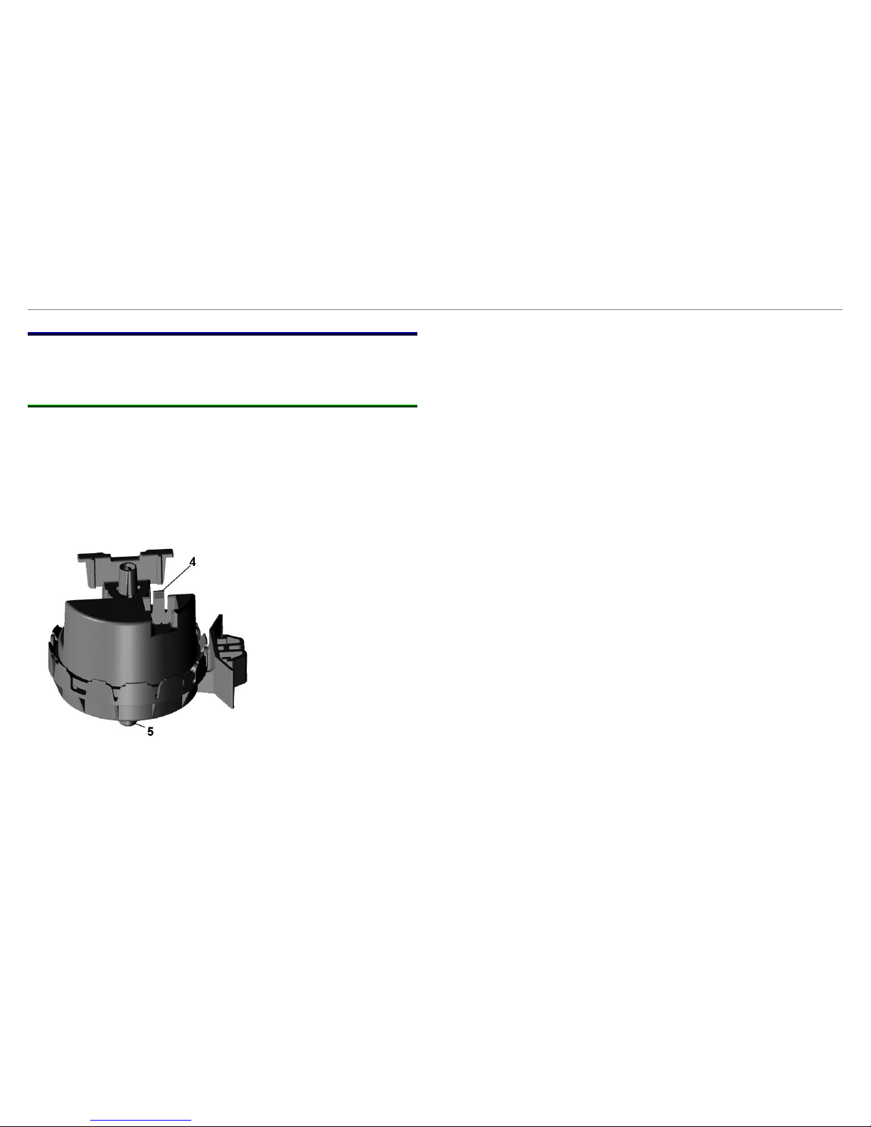
4.7 Water level sensor system
The sensor system consists of a hose, giver housing and analogue
sensor.
4.7.1 Analogue sensor
The analogue sensor is based on the piezo-electric principle and
emits a voltage between 0.5 V = and 3.5 V =. There is no point in
measuring the emitted direct voltage as the analogue value in the
customer-service test programme is indicated on the display. The
analogue sensor is responsible for the different water levels in the
various wash programmes.
4
Connecter plag
5
Analogue sensor
 Loading...