

Page 1
CTFID
VP-CFGSFT
en User’s Manual
Page 2

Page 3

CTFID Table of Contents | en 3
Table of Contents
1 Getting Started 4
1.1 System Requirements 4
1.2 Compatible Devices 5
2 Installing the CTFID 6
3 Connections 10
3.1 Connecting the VP-USB Configuration Tool 10
3.2 Connecting the VP-RS2BLNX Configuration Tool 11
3.3 Connecting the AutoDome RS-232 13
3.4 Accessing the CTFID Application 14
4 Using the Configuration Tool 17
4.1 Main Menu Buttons 18
4.1.1 Overview Window 18
4.1.2 Offline Mode Window 19
4.1.3 Online Mode Window 20
4.1.4 Virtual Keyboard Window 20
4.1.5 AUX Commands Dialog Box 22
4.1.6 Logs Window 23
4.2 Central Workspace 25
4.3 System Feedback 26
4.4 Operations Column 27
5 Configuration Settings 28
5.1 Downloading Configuration Settings 28
5.2 Uploading/Downloading Specific Setting Changes 29
5.3 Changing an Existing Configuration File 30
5.4 Uploading All Configuration Settings to a Device 30
5.5 Migrating Configuration Settings 31
5.6 Downloading Diagnostic Log Information 33
5.7 Uploading Firmware to a Device 34
5.8 Uploading Firmware to a VG4 Series AutoDome 34
6 Settings Tree Options 36
7 Troubleshooting 51
7.1 Confirm System Connection between the PC and the Device 51
7.2 Device Error 51
7.3 Accessing the Version 52
8 AUX Keyboard Commands 53
Bosch Security Systems, Inc. User’s Manual F.01U.141.545 | 3.09 | 2009.10
Page 4

4 en | Getting Started CTFID
1 Getting Started
The Configuration Tool for Imaging Devices (CTFID) includes two components:
– One (1) CD-ROM containing the software application
– Configuration Tool hardware (VP-USB, interface between your computer and an imaging
device)
1.1 System Requirements
The following are the minimum system requirements to run the Configuration Tool for Imaging
Devices software application:
– PC operating platform: Windows® 98 Second Edition, Windows® Millennium Edition,
Windows® 2000, Windows XP®, or Windows® Vista
– Processor: 200 MHz Pentium with MMX (or equivalent)
– RAM memory: 256 MB (dependent upon the operating system)
– Hard disk space: 50 MB
– Video system: 1024 x 768 with 16-bit color
– CD-ROM drive, if installing the software from a CD
– Connectivity: a free USB port (1.1 or higher)
– Connectivity through serial interface
F.01U.141.545 | 3.09 | 2009.10 User’s Manual Bosch Security Systems, Inc.
Page 5

CTFID Get ti ng S t a r te d | e n 5
1.2 Compatible Devices
The CTFID uses Bilinx technology, a bidirectional communication method, embedded in the
video signal of all of the latest Bosch AutoDome, Dinion, Dinion
FlexiDome 2X, and UnityDome cameras (see the table below for a list of compatible devices).
Compatible devices Compatible devices
AutoDome 25X Day/Night (5.2+) VG4 300 Series 18X Color
AutoDome 18X Day/Night (5.2+) VG4 200 Series 36X Day/Night
AutoDome 18X Color (5.2+) VG4 200 Series 26X Day/Night
AutoDome 18X Monochrome (5.2+) VG4 200 Series 18X Day/Night
AutoDome G3 Basic (5.2+) VG4 200 Series 18X Color
AutoDome 26X (5.2+) VG4 500 Series Fixed Day/Night
AutoDome 26X Day/Night (5.2+) VG4 500 Series Fixed Color
AutoDome 25X Day/Night (5.1) VG4 300 Series Fixed Day/Night
AutoDome 18X Day/Night (5.1) VG4 300 Series Fixed Color
AutoDome 18X Color (5.1) VG4 200 Series Fixed Day/Night
AutoDome 18X Monochrome (5.1) VG4 200 Series Fixed Color
AutoDome G3 Basic (5.1) AutoDome Easy II
Dinion XF LTC 0385 FlexiDome 2X VDN-498
Dinion XF LTC 0485 FlexiDome VF VDM-345 Series
Dinion XF LTC 0510 FlexiDome XT VDM-355 Series
Dinion XF LTC 0610 FlexiDome VF VDC-445 Series
Dinion XF LTC 0495 FlexiDome XT VDC-455 Series
Dinion XF LTC 0620 FlexiDome XF VDC-485 Series
Dinion 2X LTC 0498 FlexiDome DN VDN-495 Series
Dinion 2X LTC 0630 UnityDome DN VG4-162 & VG4-164 Series
Dinion LTC 0335 UnityDome DN VG4-152 & VG4-154 Series
Dinion LTC 0355 UnityDome XF VG4-161 & VG4-163 Series
Dinion LTC 0356 UnityDome XF VG4-151 & VG4-153 Series
Dinion LTC 0435 HSPU UPH-2D10
Dinion LTC 0455 HSPU UPH-2D10W
VG4 500 Series 36X Day/Night HSPU UPH-2D15
VG4 500 Series 26X Day/Night HSPU UPH-2D15W
VG4 500 Series 18X Day/Night HSPU UPH-3D10
VG4 500 Series 18X Color HSPU UPH-3D10W
VG4 300 Series 36X Day/Night HSPU UPH-3D15
VG4 300 Series 26X Day/Night HSPU UPH-3D15W
VG4 300 Series 18X Day/Night
XF
, Dinion 2X, FlexiDome,
NOTICE!
The only devices available for use with the BiCom over serial interface are the 200, 300, and
500 AutoDome Series.
Bosch Security Systems, Inc. User’s Manual F.01U.141.545 | 3.09 | 2009.10
Page 6
6 en | Installing the CTFID CTFID
2 Installing the CTFID
This chapter includes instructions for installing the software for the Configuration Tool for
Imaging Devices. Prior to connecting to a compatible device, install the software.
Installing the Software
1. Insert the supplied CD into your CD drive. If the InstallShield Wizard does not start
automatically, open the CD manually by clicking Start, Run, Browse. Locate and open the
autorun.exe file. The Configuration Tool for Imaging Devices prompts you to select one
of the following options: Install Configuration Tool, User Guide, View the Readme file,
and Exit.
Figure 2.1 Installing the configuration tool
2. Press Install Configuration Tool to install the firmware.
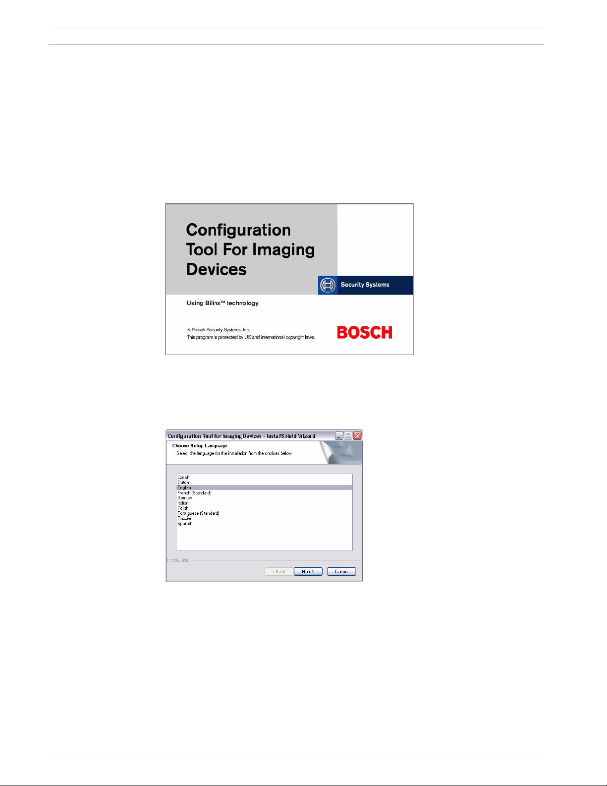
3. The Configuration Tool for Imaging Devices - InstallShield Wizard automatically prompts
you to select one of the following languages: Czech, Dutch, English, French (Standard),
German, Italian, Polish, Portuguese (Standard), Russian, and Spanish.
Figure 2.2 Choosing the setup language
F.01U.141.545 | 3.09 | 2009.10 User’s Manual Bosch Security Systems, Inc.
Page 7
CTFID Installing the CTFID | en 7
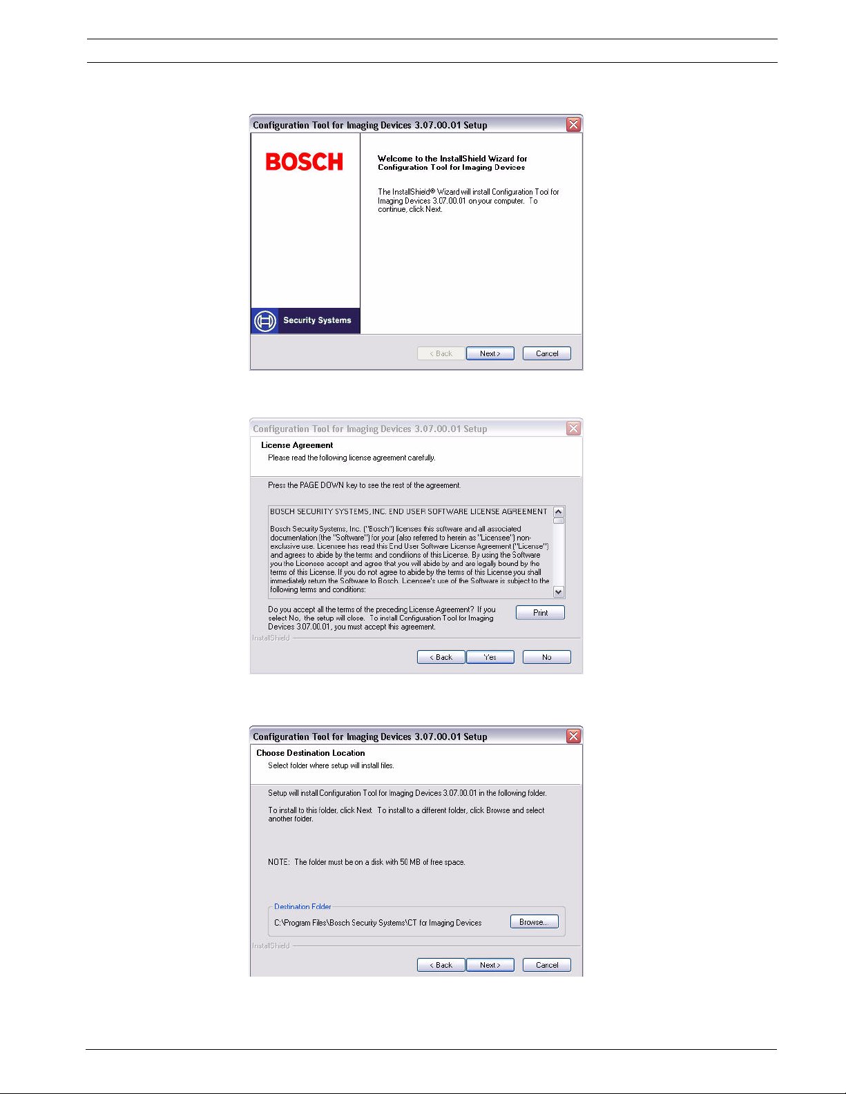
4. Select a language, then click Next.
Figure 2.3 Initiating the InstallShield Wizard setup
5. Click Next to continue installing the application, or click Cancel to discontinue.
Figure 2.4 Confirming the License Agreement
6. Click Yes to accept the terms of the License Agreement, or click No to discontinue.
Figure 2.5 Determining the destination folder
Bosch Security Systems, Inc. User’s Manual F.01U.141.545 | 3.09 | 2009.10
Page 8
8 en | Installing the CTFID CTFID
7. To accept the default choice, click Next. To change the installation directory, click
Browse and navigate to a directory. Then click Next.
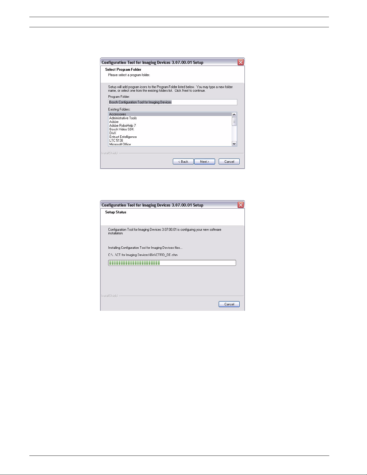
Figure 2.6 Naming the program folder
8. Click Next to accept the default program folder, Bosch Configuration Tool for Imaging
Devices, or type a new name for the folder and click Next.
Figure 2.7 Copying the files
F.01U.141.545 | 3.09 | 2009.10 User’s Manual Bosch Security Systems, Inc.
Page 9
CTFID Installing the CTFID | en 9
9. Click Next to begin copying the files to the folder indicated or click Cancel to
discontinue.
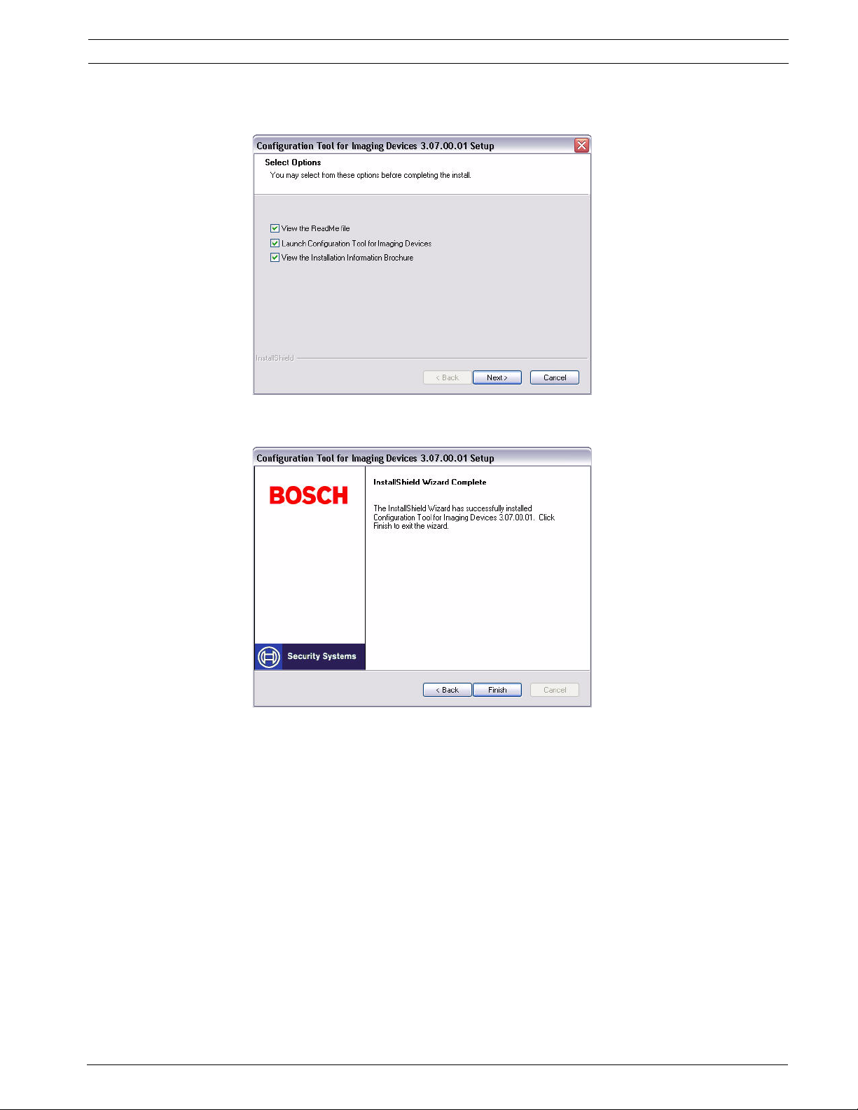
Figure 2.8 Selecting final options
10. Check the appropriate box(es), then click Next.
Figure 2.9 Completing the installation
11. Click Finish to complete the installation. The CTFID application is launched and/or the
Instruction Manual and readme file are automatically displayed if the appropriate check
box(s) are selected.
Bosch Security Systems, Inc. User’s Manual F.01U.141.545 | 3.09 | 2009.10
Page 10
10 en | Connections CTFID
3 Connections
The CTFID is supplied with a VP-USB adaptor that plugs into any USB-compliant port
supported by a Windows® operating system. Once the CTFID software is loaded, the adaptor
communicates over the video signal from any Bilinx-enabled camera or AutoDome.
There are three (3) possible connection types to link the CTFID software to the imaging
device. The first two (2) choices communicate via coax using the Bilinx protocol. These two
(2) choices connect to either the USB or serial COMM port of the PC. The third choice is
direct RS-232 connection between the PC COMM port and the imaging device (AutoDome
only).
3.1 Connecting the VP-USB Configuration Tool
It is recommended that the CTFID software be installed prior to connecting the hardware to
the USB port. Refer to Section 2 Installing the CTFID, page 6 for additional information.
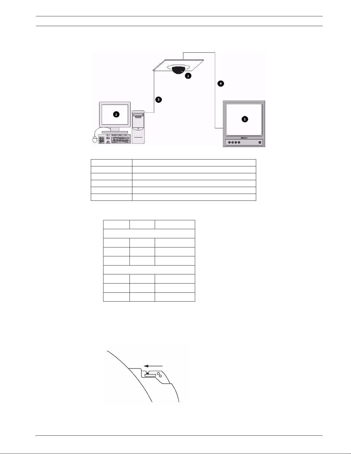
To see the device output, use a CCTV monitor with looping inputs or a T connector (not
provided) for the coaxial cable, and plug the second coaxial cable into the CCTV monitor.
Ensure that the monitor is either auto-terminating or is set to low impedance. See Figure 3.1
for an example of a typical CCTV monitor’s connections.
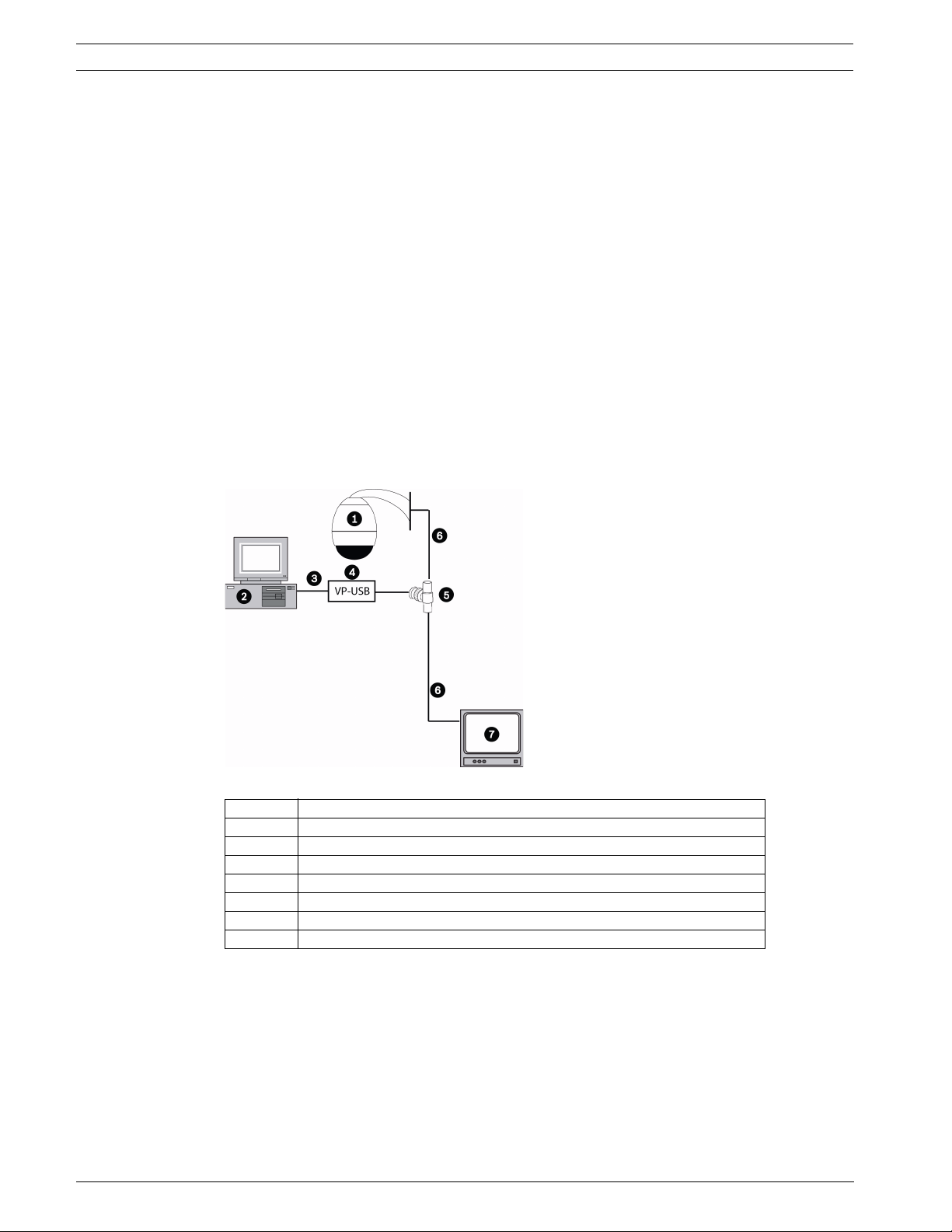
Figure 3.1 Connecting the VP-USB Configuration Tool
Number Description
1 Typical AutoDome version 5.10 or higher, and any other Bilinx device
2 PC running CTFID software
3USB port
4 VP-USB adapter
5 BNC “T” connector
6 Coax to input of monitor
7 Typical CCTV monitor
Connecting the VP-USB Configuration Tool to Your PC
1. Insert the Configuration Tool USB cable into a USB port on your computer. The other end
of the USB cable is permanently attached to the Configuration Tool hardware.
2. Connect the coax from the VP-USB to the male connection of the BNC “T” connector.
3. Connect a coaxial cable to the input of the monitor.
4. Connect the other end of the monitor’s coaxial cable into one of the female connections
on the BNC “T” connector.
5. Connect the coax from the camera to the other female connection of the BNC “T”
connector.
F.01U.141.545 | 3.09 | 2009.10 User’s Manual Bosch Security Systems, Inc.
Page 11
CTFID Connections | en 11
3.2 Connecting the VP-RS2BLNX Configuration Tool
It is recommended that the CTFID software be installed prior to connecting the hardware to
the serial port. Refer to Section 2 Installing the CTFID, page 6 for additional information.
To see the device output, use a CCTV monitor. Plug the coax connected to the imaging device
to one of the BNC connectors of the VP-RS2BLNX. Connect another coax between the second
BNC connector and the CCTV monitor. Ensure that the monitor is either auto-terminating or is
set to low impedance. See Figure 3.3 for an example of a typical CCTV monitor’s connections.
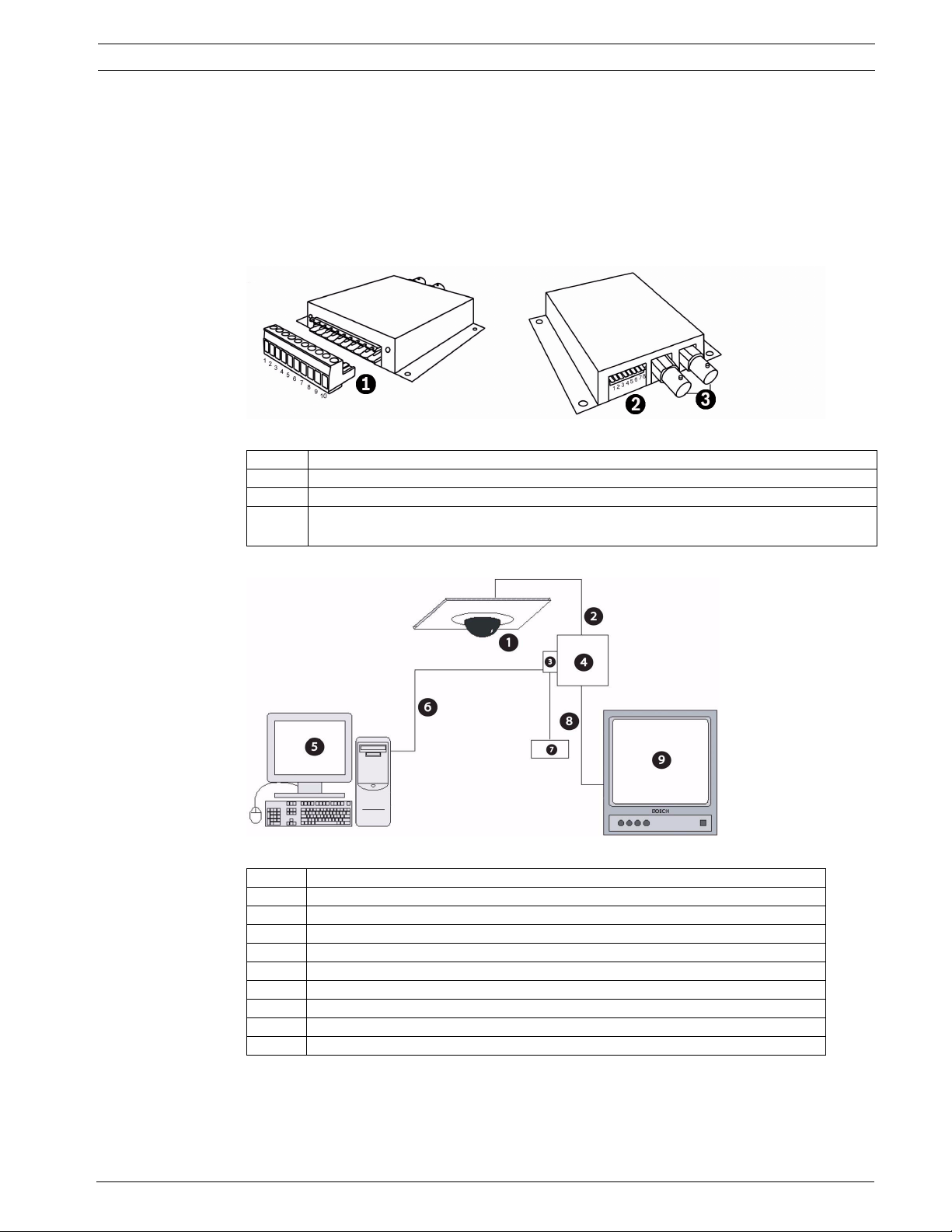
Figure 3.2 VP-RS2BLNX connections
Number Description
1 Power and serial connection
2 Selects mode and baud rate
3 BNC connections, passive loop-through, high impedance, video input 1 Vpp nominal,
2Vpp max.
Connecting the VP-RS2BLNX (Bilinx)
Figure 3.3 Connecting the VP-RS2BLNX Configuration Tool
Number Description
1 Typical AutoDome version 5.10 or higher, and any other Bilinx device
2Coax IN
3 Terminal block
4VP-RS2BLNX
5 PC running CTFID software
6 RS-232
7 Power supply (not provided)
8Coax OUT
9 Typical CCTV monitor
Bosch Security Systems, Inc. User’s Manual F.01U.141.545 | 3.09 | 2009.10
Page 12
12 en | Connections CTFID
Connecting the VP-RS2BLNX Configuration Tool to Your PC
1. Pin 1 and 2 of the terminal block are for the connections for the external power supply
not provided. The external power supply should be either 12-28 VAC (50/60 Hz) or 1240 VDC (polarity independent). Galvanically insulated from video, RS-232 ground and
encasing.
NOTICE! The Serial to Bilinx converter interface shall be supplied by a self-limited power
source of less than 15 VA. Reinforced insulation is provided between input and output by
safety transformer and distances on the PCB. USA/Canada: The Serial to Bilinx converter is a
product for INDOOR use. It is intended for use with a UL-listed Class 2 power supply.
2. Connect a cable between the terminal block of the VP-RS2BLNX Configuration Tool to
the serial port on the computer. Refer to the pin out table below for the proper
connections.
NOTICE! The VP-RS2BLNX can operate in RS-232 or RS-485 mode.
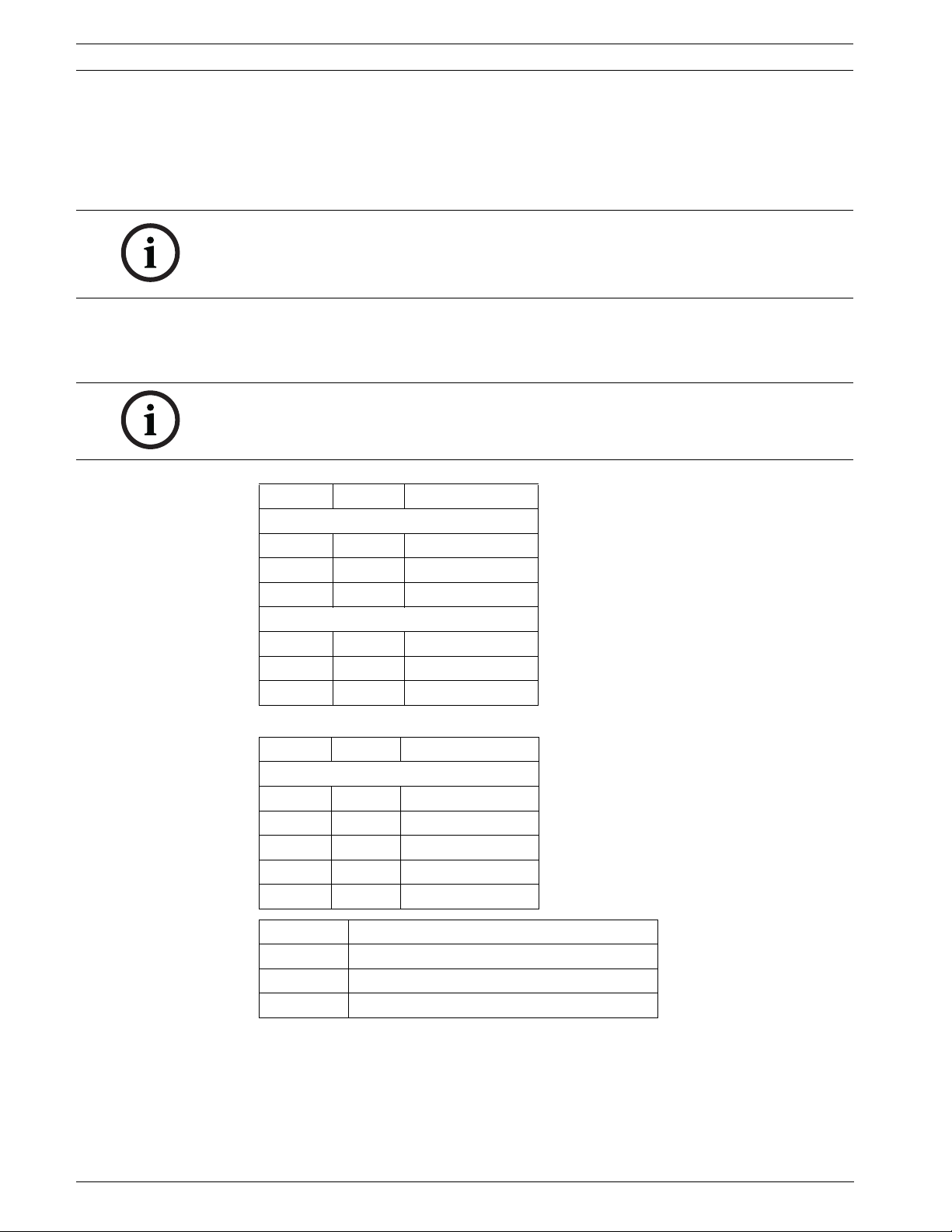
Pin # Description
PC DB9
2RxD
3TxD
5GnD
VP-RS2BLNX terminal block
Pin 3 GND
Pin 4 TxD
Pin 5 RxD
-or-
Pin # Description
VP-RS2BLNX terminal block
Pin 6 Tx/Rx+ (B)
Pin 7 Tx/Rx- (A)
Pin 8 Do not connect
Pin 9 Do not connect
Pin 10 GND
Dip switch Description
8 On: RS-485, Off: RS-232
7 RS-232 baud rate (On: 4800, Off: 9600 Bps)
7-1 RS-485 address (0 to 127)
Tab le 3 .1 Mode and Baud Rate Selections
3. Connect the coax from the Bilinx device to one of the BNCs on the VP-RS2BLNX.
4. Connect a second coaxial cable from the looping output of the VP-RS2BLNX to the input
of the CCTV monitor.
F.01U.141.545 | 3.09 | 2009.10 User’s Manual Bosch Security Systems, Inc.
Page 13
CTFID Connections | en 13
3.3 Connecting the AutoDome RS-232
Figure 3.4 Connecting the AutoDome RS-232 to the PC
Number Description
1 AutoDome 200, 300, and 500 Series
2 PC running CTFID software
3RS-232
4 Coax to input of monitor
5 Typical CCTV monitor
Connecting the AutoDome to Your PC
1. Make the RS-232 cable using the table below.
Pin # Description
PC DB9
2RxD
3 TxD
5GnD
P105 (AutoDome 200, 300, 500)
5RxD
4 TxD
6GnD
2. Connect the DB9 connector to the Com port of the PC.
3. Connect P105 to the AutoDome.
4. Use coax to connect the Video output of the AutoDome to a CCTV monitor.
5. Reposition the slide switch located on the main board of the AutoDome. Slide the switch
toward the camera head, inward and away from the LEDs. See Figure 3.5.
Figure 3.5 RS-232
Bosch Security Systems, Inc. User’s Manual F.01U.141.545 | 3.09 | 2009.10
Page 14
14 en | Connections CTFID
3.4 Accessing the CTFID Application
The CTFID uses Bilinx technology, which is a bidirectional communication method, embedded
in the video signal. Alternately, BiCom over serial interface is available to enable a connection
to the device using the serial interface.
Camera/dome settings can be changed while connected to a device in Online mode.
Alternatively, use Offline mode to download and save data so that it can be manipulated and
uploaded to the same or other similar devices.
Accessing the CTFID
1. Double-click the Configuration Tool for Imaging Devices icon located on your desktop
window.
- or -
Click the Windows Start button and select Programs. Then select the Configuration Tool
for Imaging Devices folder. Finally, select the Configuration Tool for Imaging Devices
application.
Figure 3.6 Starting the application
2. By default, the device automatically tries to connect to a device over Bilinx. The
application displays the following message for approximately 20-30 seconds:
Figure 3.7 Checking the device
F.01U.141.545 | 3.09 | 2009.10 User’s Manual Bosch Security Systems, Inc.
Page 15
CTFID Connections | en 15
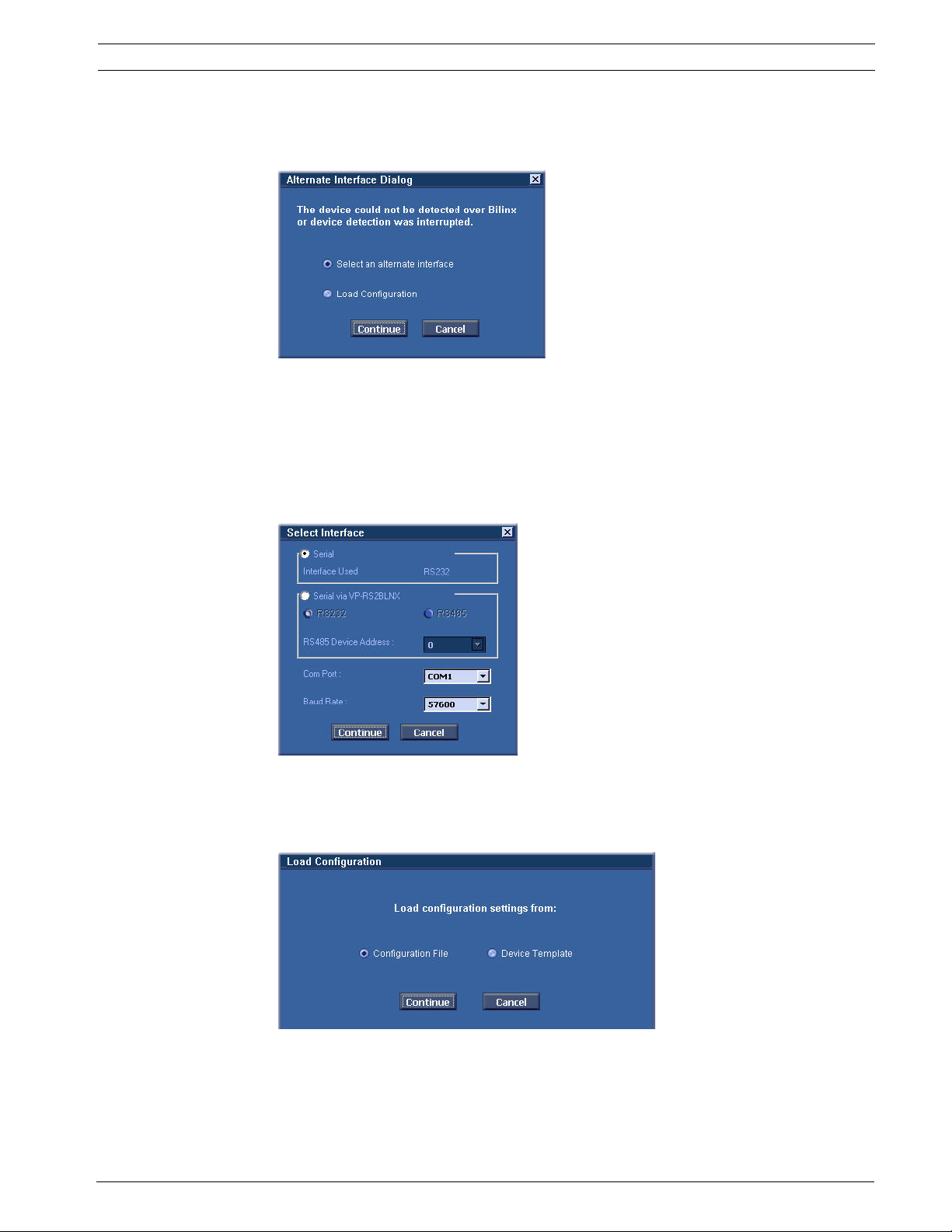
3. If a device is detected, go to Chapter 4. If a device is not detected within 1 minute, or if
the user interrupts the process by clicking the Cancel button, you are given the option to
select an alternate interface or work in an offline mode.
Figure 3.8 Alternate Interface Dialog box
4. To choose an alternate interface, click the Select an alternate interface option then,
click Continue (seeFigure 3.8, Page 15). Next, select the appropriate interface type
then, go to Step 5.
- or -
To work in an offline mode, click the Load Configuration option, then click Continue and
go to Step 6.
Figure 3.9 Select Interface
5. The application attempts to detect a device. If the application detects a device, it opens
the Overview window (see Chapter 4). If the application does not detect a device, it
opens the Load Configuration window.
Figure 3.10 Loading the configuration window
Bosch Security Systems, Inc. User’s Manual F.01U.141.545 | 3.09 | 2009.10
Page 16
16 en | Connections CTFID
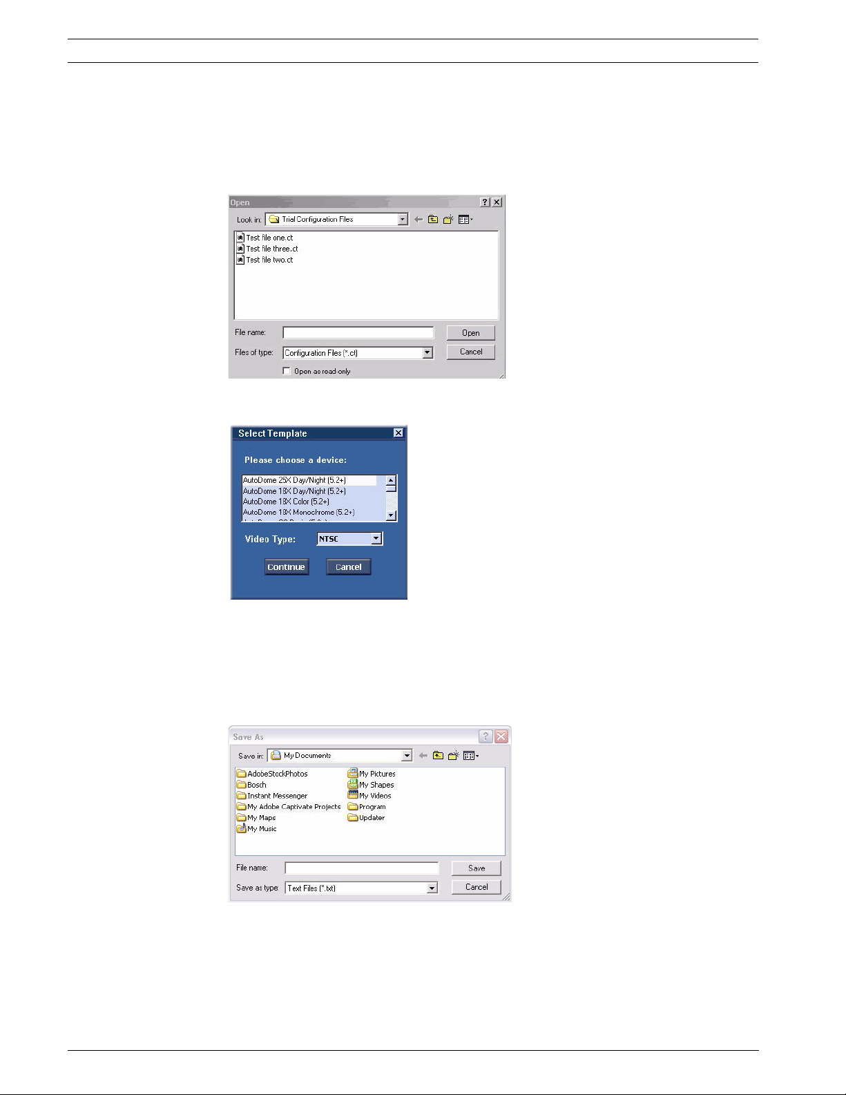
6. To open an existing configuration file, click the Configuration File option, then click
Continue and go to Step 7.
- or -
To create a new configuration file, click the Device Template option, then click Continue
and go to Step 8.
Figure 3.11 Opening the file dialog box
7. Navigate to the configuration file, then click Open. Proceed to Chapter 4.
Figure 3.12 Choosing a device
8. Select the device for which you want to create a new configuration by highlighting its
name. Then select a Video Type, NTSC or PAL, and click Continue. The application opens
the Overview window with the default settings for the device displayed.
9. Make the changes to the template and click the Save Configuration button. The
application opens the Save As dialog box.
10. Navigate to the folder where you want to save the configuration file.
11. Type a name for the configuration file in the File name field.
12. Click Save. The configuration file is saved in the specified folder.
F.01U.141.545 | 3.09 | 2009.10 User’s Manual Bosch Security Systems, Inc.
Page 17
CTFID Using the Configuration Tool | en 17
4 Using the Configuration Tool
The CTFID main screen contains all the options for changing a template, configuring a live
view, displaying specific device information, downloading information, changing device
settings, and manipulating a device. By default, the CTFID opens the Overview window in the
central workspace when started. The main screen is divided into four (4) segments, as
illustrated in Figure 4.1.
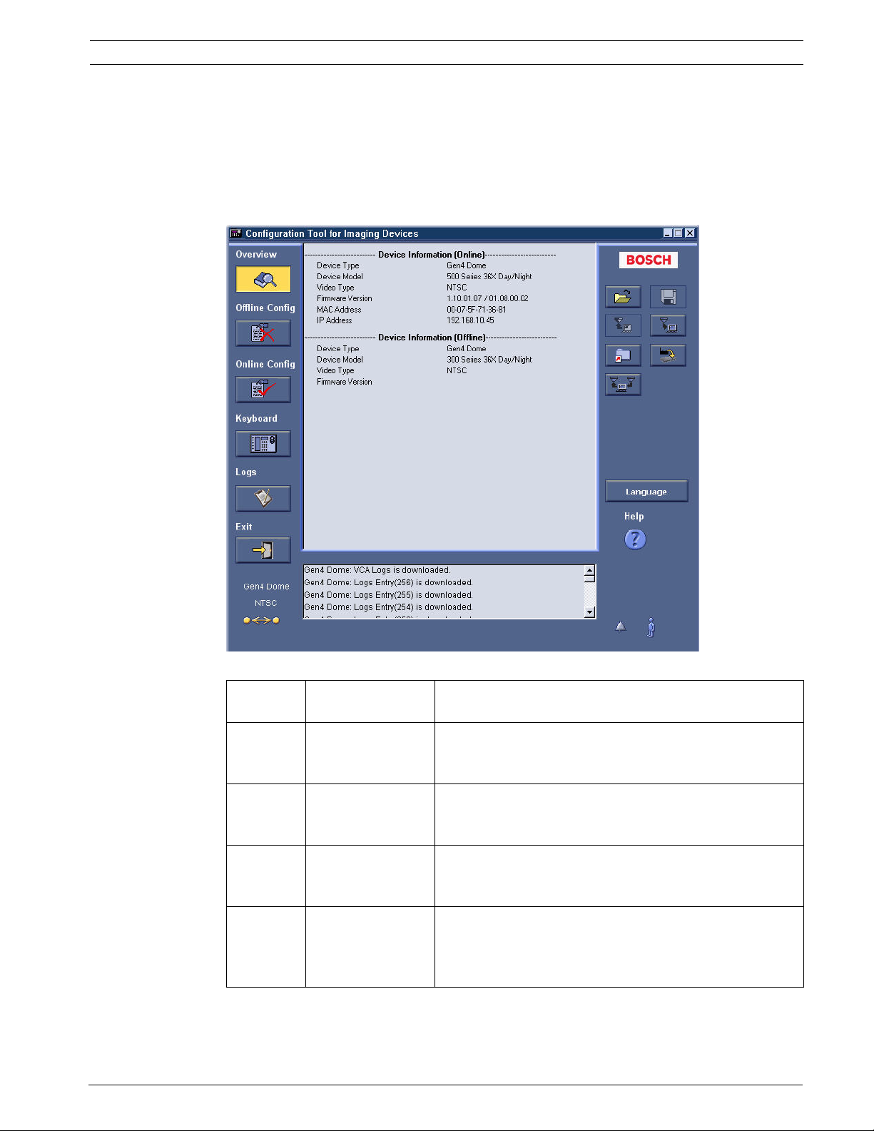
Figure 4.1 Overview/main window
Segment
reference
1 Main menu column The left-hand column represents the main menu, which
2 Central workspace The middle section represents the central workspace,
3 System feedback The bottom segment represents the system feedback,
4 Operations column The operations column includes buttons for creating,
Description Function
includes the Overview, Offline Config, Online Config,
Keyboard, Logs, and Exit buttons.
which includes device information or provides access to
user settings.
which includes device type, alarm, connectivity status, and
motion information.
saving, uploading, downloading, restoring, printing,
changing the language, and accessing the online Help
system.
Bosch Security Systems, Inc. User’s Manual F.01U.141.545 | 3.09 | 2009.10
Page 18

18 en | Using the Configuration Tool CTFID
4.1 Main Menu Buttons
Button Description
Opens the Overview window. The Overview window displays general
information about the device, the application environment, and the state of the
application. The data includes specific device information.
Opens the Offline mode window. The Offline mode window allows you to
establish settings in a new configuration file or to modify settings in an existing
configuration file.
Note: The CTFID software allows two (2) files to be open simultaneously:
– Online mode configuration file: contains the current settings for the
connected device.
– Offline mode configuration file: contains either the settings saved in a
specific configuration file or the default device settings.
Opens the Online mode window. The Online mode window displays the current
settings for the device connected to the Configuration Tool software. Changes
made to the settings in Online mode are reflected in the device.
Opens the Virtual Keyboard window. The virtual keyboard controls various
settings, depending on the device type. In Online mode, changing the settings on
this screen automatically changes the settings on the device.
Opens the Logs window. The Logs window allows you to download diagnostic
information from the connected device. The downloaded diagnostic information
can be saved as a text file.
Note: The Logs button is enabled only when the CTFID software is connected to
a VG4 Series AutoDome.
Exits the Configuration Tool for Imaging Devices.
Tab le 4 .1 Main Menu Buttons
4.1.1 Overview Window
The Overview window displays general information about the device, the application
environment, and the state of the application. The data includes specific device information
(see Figure 4.1).
F.01U.141.545 | 3.09 | 2009.10 User’s Manual Bosch Security Systems, Inc.
Page 19

CTFID Using the Configuration Tool | en 19
4.1.2 Offline Mode Window
The Offline mode window establishes settings in a new configuration file, or changes settings
in an existing configuration file. To start downloading and saving data so that it can be
manipulated and uploaded to other devices, click the Offline Config button.
Figure 4.2 Offline mode window
NOTICE! The headings and settings tree are available based on the device selected. For
detailed information about the possible settings, refer to the installation instructions manual
for the specific device.
Overwriting the Configuration Settings
If you are working in an open file and would like to open another file in Offline mode, the
following Information dialog box opens:
Figure 4.3 Information dialog box
The Information dialog box provides several options:
– Click Yes to open a Save As dialog box. Name the file and save it.
– If you click No, the changes to the file will not be saved. The Load Configuration dialog
box opens. Choose a different file or device template.
– Click Cancel and the dialog box closes.
Bosch Security Systems, Inc. User’s Manual F.01U.141.545 | 3.09 | 2009.10
Page 20

20 en | Using the Configuration Tool CTFID
4.1.3 Online Mode Window
The Online mode window allows you to view the current settings of the device connected to
the Configuration Tool for Imaging Devices. When device settings are changed in Online
mode, the changes are immediately conveyed to the remote device. To access the Online
mode window, click the Online Config button.
Figure 4.4 Online mode window
NOTICE! The headings and settings tree are available based on the device selected. For
detailed information about the possible settings, refer to the installation instructions manual
for the specific device.
4.1.4 Virtual Keyboard Window
To access the Virtual Keyboard window, click the Keyboard button. The Virtual Keyboard
window allows setting adjustments. If a PC monitor is connected to the device, the effects of
the setting changes can be viewed.
NOTICE! The layout of the Virtual Keyboard window varies depending on the device. The
functionality described below may not be available on all devices.
VG4 Series AutoDome Pan/Tilt
Place the cursor on the Pan/Tilt control (see #1 Figure 4.5), then click and hold down the left
mouse button. When used with a variable-speed device, the further the cursor is from the
center of the control, the faster the device will pan. Double-click the left mouse button to lock
the cursor to the control. Then, moving the mouse moves the device. A single left-click
releases the cursor.
F.01U.141.545 | 3.09 | 2009.10 User’s Manual Bosch Security Systems, Inc.
Page 21

CTFID Using the Configuration Tool | en 21
Figure 4.5 VG4 Series AutoDome Virtual Keyboard window
Number Button Description
1 Pan/Tilt Moves the device.
2 AUX Opens the AUX Commands dialog box.
3 Focus Widens the scope of the focus lens.
4 Focus Narrows the scope of the focus lens.
5 Zoom Zooms in on the subject of the device.
6 Zoom Zooms out and widens the field of view.
7 Iris Increases the light level for proper exposure.
8 Iris Decreases the light level for proper exposure.
Bosch Security Systems, Inc. User’s Manual F.01U.141.545 | 3.09 | 2009.10
Page 22

22 en | Using the Configuration Tool CTFID
Dinion Virtual Keyboard
Place the cursor on the Enter control (see #5 Figure 4.6), then click once to open the Mode
menu; click once to open the submenus. Click and hold to open the Install menu; click once to
open the submenus.
Figure 4.6 Dinion Virtual Keyboard window
Number Button Description
1 Pan/Tilt Moves the cursor up.
2 Pan/Tilt Moves the cursor to the right.
3 Pan/Tilt Moves the cursor down.
4 Pan/Tilt Moves the cursor to the left.
5 Enter Opens menus and functions as an enter button.
6 AUX Opens the AUX Commands dialog box.
4.1.5 AUX Commands Dialog Box
When you click the AUX button, the AUX Commands dialog box opens. The AUX Commands
dialog box is designed to simulate the hardware keypad, and allows direct entry of the AUX
command.
To enter an AUX command:
1. Select the command type radio button on the left.
2. Enter the four-digit number in the Shot # field (or click the four numerals via the keypad).
3. Click Enter.
– The command is sent to the device. For a list of AutoDome and Dinion keyboard
commands, refer to Chapter 8.
–Although the AUX button is active for the FlexiDome and Unity Dome Series, no
additional commands are available.
–The AUX button is disabled for Dinion mid-range models (Dinion LTC 0355, Dinion
LTC 0356, Dinion LTC 0435, Dinion LTC 0455, FlexiDome VF VDM-345 Series,
F.01U.141.545 | 3.09 | 2009.10 User’s Manual Bosch Security Systems, Inc.
Page 23

CTFID Using the Configuration Tool | en 23
FlexiDome XT VDM-355 Series, FlexiDome VF VDC-445 Series, FlexiDome XT VDC455 Series).
Figure 4.7 AUX Commands dialog box
Number Description
1 Initiates camera movement to a shot. The shot is selected by entering a four-digit
shot number in the Shot # field.
2 Defines a shot.
3 Turns on an auxiliary camera function.
4 Turns off an auxiliary camera function.
5Displays numerical AUX commands entered.
6 Numerical keypad.
4.1.6 Logs Window
To access the Logs window, click the Logs button. The Logs window allows you to download
and view the diagnostic log information from the connected device.
NOTICE! The Logs window is enabled only when a VG4 Series AutoDome camera is connected
to the CTFID. The functionality described below may not be available for all devices.
Bosch Security Systems, Inc. User’s Manual F.01U.141.545 | 3.09 | 2009.10
Page 24

24 en | Using the Configuration Tool CTFID
Figure 4.8 Logs Window
How to Download and Save Diagnostic Log Information
1. Click the Download button.
2. Click the Save Logs button. The Save As dialog box opens.
Figure 4.9 Save As dialog box
3. Navigate to the folder where you want to save the log file.
4. Type a name for the log file in the File name field.
5. Click Save. The configuration file is saved in the specified folder.
F.01U.141.545 | 3.09 | 2009.10 User’s Manual Bosch Security Systems, Inc.
Page 25

CTFID Using the Configuration Tool | en 25
4.2 Central Workspace
The central workspace displays the main menu windows. For example, when the Offline
Config button is clicked and a configuration file or device template has been selected, the
central workspace displays a two-pane window. The settings tree and the windows in the
central workspace vary, depending on the device selected. The settings are divided into
different groups. For detailed information about the possible settings, refer to the installation
instructions manual for the specific device.
Figure 4.10 Offline configuration, settings tree, and device settings
Bosch Security Systems, Inc. User’s Manual F.01U.141.545 | 3.09 | 2009.10
Page 26

26 en | Using the Configuration Tool CTFID
4.3 System Feedback
The system feedback section includes device, alarm, and motion information. The Status text
box displays specifics on the connected device in Online mode.
Figure 4.11 System feedback
Number Description
1 Indicates the name of the device currently connected in Online mode.
2 Indicates the video type of the device currently connected in Online mode.
3 Confirms that the device is connected to the Configuration Tool for Imaging
Devices.
When a device is not connected, a red X appears.
4 Confirms that the application is displaying the current device settings. Any
changes made to the settings are immediately applied. Other messages may
include:
– Confirmation message: When you change settings on the device, the setting
change is noted in this box. If no message appears, the device has not
received the change.
– Error message: If there is a problem with the device, an error message may
appear. Possible causes may be a connection problem or an incompatibility
issue.
5 Detects the alarm condition of a connected device (icon turns red). Click the icon
to acknowledge the alarm; the icon then returns to its normal gray color.
Note: When the VG4 Series AutoDome detects the alarm condition, the alarm icon
turns red and remains red until the alarm condition is cleared. The VG4 Series will
not acknowledge an alarm by the icon being clicked.
Note: The Alarm icon will always be present, but the associated functionality may
not be available for all devices.
6 Detects motion of a connected device (icon turns red). Click the icon to
acknowledge the motion. The icon returns to its normal gray color.
Note: The Motion icon will always be present, but the associated functionality may
not be available for all devices.
F.01U.141.545 | 3.09 | 2009.10 User’s Manual Bosch Security Systems, Inc.
Page 27

CTFID Using the Configuration Tool | en 27
4.4 Operations Column
Button Description
Creates a new or opens an existing configuration file. When in Online mode,
the configuration file opens in Offline mode by default.
Saves the configuration file on which you are working.
Uploads the open configuration file to the device. The Upload Configuration
button is only available when working in Offline mode.
Downloads the configuration file from the device to Offline mode.
Note: If you click this button when working in Offline mode and are not
connected to a device, the following error message will appear: There is no
compatible device currently connected.
Uploads a firmware upgrade directly to the device. Note: Not available on the
following models: Dinion LTC 0355, Dinion LTC 0356, Dinion LTC 0435, Dinion
LTC 0455, FlexiDome VF VDM-345 Series, FlexiDome XT VDM-355 Series,
FlexiDome VF VDC-445 Series, FlexiDome XT VDC-455 Series.
Restores all settings in the device to factory defaults. Configuration Tool for
Imaging Devices subsequently downloads all settings from the device.
Note: The functionality described above is only available when a VG4 Series
AutoDome camera is connected to Configuration Tool For Imaging Devices.
Prints the offline configuration settings when in Offline mode.
Migrates the current offline or online settings of one AutoDome to another
AutoDome.
Automatically checks all of the Select check boxes and uploads all changes to
the device (only appears when in Offline mode).
To upload only a few device settings, click the appropriate check boxes. The
Select check boxes specifically note which changes are to be uploaded to the
device. This is useful if only a few settings are to be changed. Uploading all of
the settings can be a lengthy operation.
– To upload all settings, click the Select All button; all check boxes are
automatically checked. The button changes to Deselect All.
– To remove all checks, click the Deselect All button.
Changes the language displayed by the Configuration Tool software.
Note: The application must be restarted in order to affect the language setting
change.
Accesses the Configuration Tool software online Help system.
Tab le 4 .2 Operations buttons
Bosch Security Systems, Inc. User’s Manual F.01U.141.545 | 3.09 | 2009.10
Page 28

28 en | Configuration Settings CTFID
5 Configuration Settings
The configuration buttons enable the user to upload and download setting changes from a
device. It is more efficient to only download/upload the settings that have been modified.
5.1 Downloading Configuration Settings
1. Click the Offline Config button or the Online Config button. The Offline Configuration
window or Online Configuration window opens in the central workspace.
Figure 5.1 Offline Configuration window
2. Click Select All or check the appropriate boxes for individual settings. If the Download
Configuration button is pressed before selecting the check boxes, you receive an error.
3. Click the Download Configuration button. The device settings are automatically
downloaded into the application and displayed in the Offline Configuration window.
This operation may be a lengthy process. A progress bar is displayed at the bottom of the
window, indicating the status of the operation.
Figure 5.2 Progress bar
4. The CTFID displays a confirmation message.
F.01U.141.545 | 3.09 | 2009.10 User’s Manual Bosch Security Systems, Inc.
Page 29

CTFID Configuration Settings | en 29
5.2 Uploading/Downloading Specific Setting Changes
1. In Offline mode, open the configuration file that contains the current settings for the
device.
Figure 5.3 Uploading and Downloading Specific Changes
NOTICE! If you do not have such a file, connect to the device in Online mode. The current
settings are automatically downloaded upon connection. Click the Save button to display the
Save As dialog box. Navigate to the folder where the file is to be saved. Name the file and click
OK. In Offline mode, open the configuration file you saved.
2. Navigate to the setting(s) you want to change. For example, to change the Max Gain
Level on an AutoDome Security Camera, navigate to the Offline Configuration window,
Camera Setting Group 1.
3. Move the Max Gain Level slide from 2 to 6.
4. Click the check box(es) in the Select column.
5. Click the Upload or Download Configuration button.
A confirmation dialog box opens to confirm that you want to replace the selected settings
in the offline configuration file with the specific current device settings. Only the selected
settings are uploaded or downloaded.
6. Click Yes to begin uploading or downloading the settings. Since this can be a lengthy
operation, depending on the number of configuration changes made, a progress bar is
displayed at the bottom of the window to indicate the progress status of the operation
(see Figure 5.2).
7. A confirmation message is displayed.
NOTICE! If you have a number of devices that require the same change of settings, you can
move from device to device, leaving the application open and uploading or downloading the
same Select settings from the Offline mode configuration file. The Select check boxes are
NOT saved when you save and close the configuration file.
Bosch Security Systems, Inc. User’s Manual F.01U.141.545 | 3.09 | 2009.10
Page 30

30 en | Configuration Settings CTFID
5.3 Changing an Existing Configuration File
1. Open the configuration file.
2. Navigate to the window that displays the setting(s) that you want to change.
Figure 5.4 Settings tree display window
3. Click the Save Configuration button.
5.4 Uploading All Configuration Settings to a Device
1. In Offline mode, either create a new configuration file or open the configuration file that
contains the settings to upload.
2. Click Select All. The Select check boxes are all checked.
3. Click the Upload Configuration button.
A confirmation dialog box opens to confirm you want to replace the current device
settings with those in the offline configuration file.
4. Click Yes to begin uploading the settings. Depending on the number of configuration
changes made, a progress bar is displayed at the bottom of the window to indicate the
progress status of the operation.
Figure 5.5 Progress bar indicator
5. The CTFID displays a confirmation message.
F.01U.141.545 | 3.09 | 2009.10 User’s Manual Bosch Security Systems, Inc.
Page 31

CTFID Configuration Settings | en 31
5.5 Migrating Configuration Settings
The Migration feature allows an operator to download the configuration settings of one
AutoDome then upload those settings to another AutoDome. This feature ensures that the
settings of each AutoDome in a surveillance system are configured the same way.
The CTFID saves downloaded settings in a configuration file (.ctm) on the operator’s
computer. To upload the settings stored in the .ctm file, the operator connects another
AutoDome to the computer that contains the CTFID application and has access to the
configuration file. Next, the operator uses the Migration upload utility to copy the settings in
the configuration file to the AutoDome.
Note: Migration is available for transferring settings only between AutoDomes. If you attempt
to migrate settings between an AutoDome and another imaging device or between two nonAutoDome imaging devices, the CTFID relays a message that the imaging devices are
incompatible.
1. Connect an AutoDome to a computer that contains the CTFID application.
Ensure that you can connect this computer to the AutoDome that is to upload the
configuration settings.
2. Launch the CTFID application on a computer that you can connect to different
AutoDomes.
3. Configure the offline or online settings for the AutoDome using the CTFID main screen.
4. Click the Migration button.
Figure 5.6 Migration window
5. Select the Download radio button and click OK.
The CTFID collects the parameters for each AutoDome setting, then opens the Save As
dialog box.
Figure 5.7 Migration Save As dialog box
6. Navigate to the directory in which you want to store the configuration file (.ctm).
7. Type a name for the file in the File name input box and click Save.
You return to the CTFID main screen.
8. Disconnect the AutoDome from the computer.
9. Connect the AutoDome that is to upload the settings to the computer.
10. Launch the CTFID application and ensure that the tool connects to the AutoDome.
Bosch Security Systems, Inc. User’s Manual F.01U.141.545 | 3.09 | 2009.10
Page 32

32 en | Configuration Settings CTFID
11. Click the Migration button and select the Upload radio button.
Figure 5.8 Migration window
12. Click OK.
The CTFID opens the Open dialog box.
Figure 5.9 Migration Open dialog box
13. Navigate to the directory that contains the configuration file, then select the file (.ctm)
and click Open.
The CTFID begins to upload the settings in the configuration file to the AutoDome.
F.01U.141.545 | 3.09 | 2009.10 User’s Manual Bosch Security Systems, Inc.
Page 33

CTFID Configuration Settings | en 33
5.6 Downloading Diagnostic Log Information
The Logs window allows you to download and view the diagnostic log information from the
connected device.
1. Click the Logs button.
Figure 5.10 Logs window download diagnostic log information
2. Click the Download button.
3. Click the Save Logs button.
NOTICE! The Logs window is only enabled when a VG4 Series AutoDome camera is connected
to the Configuration Tool for Imaging Devices. The functionality described may not be
available for all devices.
Bosch Security Systems, Inc. User’s Manual F.01U.141.545 | 3.09 | 2009.10
Page 34

34 en | Configuration Settings CTFID
5.7 Uploading Firmware to a Device
To upload firmware to a device, updates are available on the boschsecurity.com website or
call technical support for information on receiving a CD-ROM.
1. Click the Upload Firmware button.
Figure 5.11 Open F ile dialog box
2. Navigate to the folder that contains the .img file.
3. Double-click the .img file to execute the upgrade. The upload process erases the existing
firmware and loads the new firmware into the device.
5.8 Uploading Firmware to a VG4 Series AutoDome
To upload firmware to a device, updates are available on the boschsecurity.com website or
call technical support for information on receiving a CD-ROM. Refer to the VG4 Firmware
Update Manual for more information about upgrading a VG4 Series AutoDome with the CTFID
tool.
1. Click the Upload Firmware button.
Figure 5.12 Ser vice Pack dialog box
F.01U.141.545 | 3.09 | 2009.10 User’s Manual Bosch Security Systems, Inc.
Page 35

CTFID Configuration Settings | en 35
2. Navigate to the Service Pack folder.
3. Click the Select button.
Figure 5.13 Firmware upload selection dialog box
4. Select the subcomponents you want to update.
5. Click the Upload Firmware button. The upload process erases the existing firmware and
loads the new firmware into the device.
Bosch Security Systems, Inc. User’s Manual F.01U.141.545 | 3.09 | 2009.10
Page 36

36 en | Settings Tree Options CTFID
6 Settings Tree Options
Options available within the settings tree will vary depending on the device selected. Refer to
the table below for available features.
Feature Description Device Default Options
Action Enables the operating mode to
be selected when an alarm is
activated.
Active Controls how the alarm input is
activated.
Options include:
None: Disabled.
High: Alarm is activated when a
logic high is received.
Low: Alarm is activated when a
logic low is received.
Address Allows the appropriate dome to
be operated via the numerical
address in the control system.
The address may be set locally
using the Bilinx Configuration
Tool for Imaging Devices (CTFID)
or remotely using the Fast
Address function (see Fast
Address).
Alarm Action Selects the operating mode of
the camera when the alarm input
is active.
Alarm Input Triggers an alarm when the input
changes the condition.
Options include:
N.O. (Normally Open, dry
contact).
N.C. (Normally Closed, dry
contact).
N.C.S. (Normally Closed
Supervised contact, available
only for alarm inputs 1 and 2).
N.O.S. (Normally Open
Supervised contact, available
only for alarm inputs 1 and 2).
Alarm Inputs Select none to disable the alarm
input. Select active-high or
active-low for the alarm input
connector.
Dinion
XF
None None, Mode 1,
Mode 2, Mode 3
XF
Dinion
G3A Series, ENV Series,
None None, High, Low
0000 (none)
VG4 Series
Dinion 2X None None, Mode 1,
Mode 2, Mode 3,
Mode 4, Mode 5,
Mode 6, Mono
VG4 Series N.O. N.O., N.C.,
N.C.S., N.O.S.
Dinion 2X, UPH Series None None, High, Low,
Mode 1, Mode 2,
Mode 3
F.01U.141.545 | 3.09 | 2009.10 User’s Manual Bosch Security Systems, Inc.
Page 37

CTFID Settings Tree Options | en 37
Feature Description Device Default Options
Alarm Output VMD: Output relay closes on
VMD alarms.
External device: Make the output
relay available to remote
communication devices.
Dinion 2X, UPH Series VMD External Device,
VMD, Mono
Mode Active, IR
Filter Toggle,
Remote
Night mode active: Output relay
closes when camera is in
monochrome mode.
Filter toggle: Output relay closes
just before the IR filter starts
moving and opens when video
level has stabilized (2 to 3
seconds).
ALC Level
(Automatic Light
Control)
Automatically adjusts the camera
according to the brightness of
the scene.
Dinion 2X, Dinion
Dinion
FlexiDome, FlexiDome 2X
XF
,
0 -15 to +15
Unity, UPH Series
ALC Speed
(Automatic Light
Controls the speed for the videolevel control loop.
Control)
Area Select Controls the quadrant that you
Dinion 2X, Dinion
FlexiDome 2X,
Unity, UPH Series
XF
Dinion
, UPH Series
XF
,
Medium Fast
Medium
Slow
11 to 4
are editing.
Area State Actively checks for motion in a
Dinion
XF
, UPH Series
On On, Off
predefined area.
AutoBaud Activates AutoBaud. VG4 Series On On, Off
Auto Black Boosts the video signal level to
produce a full amplitude video
signal even when the scene
contrast is less than full range
(e.g. glare, fog, mist etc.). The
darkest part of the signal is set to
XF
Dinion
Dinion
FlexiDome 2X
FlexiDome
Unity
UPH Series
On On, Off
black and the lightest part to
white, thus increasing the
contrast.
Auto Focus Continuously adjusts the lens
automatically to the correct focus
G3A Series, ENV Series,
VG4 Series
Manual Spot,
Constant, Manual
for the sharpest picture.
Options include:
Spot: Adjusts the auto focus to
the center of the image.
Constant: Sets the auto focus to
on for the entire image.
Manual: Disables the auto focus
and sets the focus for manual
operation.
Bosch Security Systems, Inc. User’s Manual F.01U.141.545 | 3.09 | 2009.10
Page 38

38 en | Settings Tree Options CTFID
Feature Description Device Default Options
Auto Iris Automatically adjusts the lens to
allow the correct illumination of
G3A Series, ENV Series,
VG4 Series
Constant Constant, Manual
the camera sensor. This type of
lens is recommended for use
where there are low light or
changing light conditions.
Options include:
Constant: Sets the auto iris
function to a constant value for
auto iris operation.
Manual: Disables the auto iris
function and sets the iris control
for manual operation.
Auto Iris Level Increases or decreases
brightness according to the
G3A Series, ENV Series,
VG4 Series
81 to 15
amount of light.
Auto Pan Speed Continuously pans the camera at
a speed between right and left
G3A Series, ENV Series,
VG4 Series
30 1 to 60
limit settings.
Auto Pivot Tilts the camera through the
vertical position as the camera is
G3A Series, ENV Series,
VG4 Series
On On, Off
rotated to maintain the correct
orientation of the image.
Auto SensUP Max Sets the limit for sensitivity when
VG4 Series 15x 2x, 4x, 7.5x, 15x
the shutter speed is set to Auto
SensUP.
AUX Enters the Aux Command dialog
box where you send control
commands to the camera.
VG4 Series 0 0-99 See
Section 8 AUX
Keyboard
Commands,
page 53.
B-gain Adjusts the blue gain to optimize
the white point.
Dinion 2X,
XF
Dinion
0-5 to +5
LTC 0485,
LTC 0610,
LTC 0495,
LTC 0620,
Dinion LTC 0435,
LTC 0455,
FlexiDome VF VDC-445
and XT, FlexiDome 2X
VDC-455, Unity Dome,
UPH Series
Backlight
Compensation
(BLC)
Optimizes the video level for the
selected area of the image. Parts
outside this area may be
underexposed or overexposed.
G3A Series, ENV Series,
VG4 Series,
XF
Dinion
, Dinion
FlexiDome, Unity
Off On, Off
F.01U.141.545 | 3.09 | 2009.10 User’s Manual Bosch Security Systems, Inc.
Page 39

CTFID Settings Tree Options | en 39
Feature Description Device Default Options
Baud Rate The speed at which
telecommunicated data is
transmitted, measured in bytes
per second (Bps).
G3A Series, ENV Series,
VG4 Series*
9600 9600, 19200,
38400, 57600
2400*, 4800*,
9600*, 19800*,
38400*, 57600*
BiPhase/Audio Turns BiPhase/Audio on and off.
VG4 Series BiPhase BiPhase, Audio
(Note: Audio is intended for a
VG4 with an Ethernet module.
Selecting audio disables Biphase
communications.)
Black Level The level of the video signal that
corresponds to the maximum
Dinion 2X, Dinion
FlexiDome 2X, UPH Series
XF
0 -55 to +55
limits of the black areas of the
picture.
Blanking Cuts off the electron beam in a
camera pickup device or picture
G3A Series, ENV Series,
VG4 Series
Not
Blanked
Not Blanked,
Blanked
tube during the retrace period. It
is a signal that is composed of
recurrent pulses at line and field
frequencies. It is intended
primarily to make the retrace on
a pickup device or picture tube
invisible.
BLC Level Electronically compensates for
high background lighting to give
XF
Dinion
Unity, UPH Series
0 -15 to +15
detail that would normally be
silhouetted.
BLC Mode Toggles the compensation for
UPH Series Off On, Off
high background lighting to give
detail that would normally be
silhouetted
Cable Comp Level Prevents image degradation
Dinion 2X, Dinion
XF
(not active) 0 to 15
caused by signal losses when
transmitting video over long
cable lengths.
Cable Comp Type Allows you to choose the coax
being used. If unknown, select
Default. Note: Anything above
Dinion 2X, Dinion
XF
Off Off, Default,
RG59,
Coax 12, Coax 6
1,000 ft. may cause a decrease in
picture quality.
Camera Buttons Prevents unauthorized change of
the camera settings by disabling
the buttons.
Dinion 2X, Dinion
Dinion,
FlexiDome, FlexiDome 2X,
XF
,
Enabled Enabled,
Disabled
Unity, UPH Series
Camera Height The straight vertical height in
respect to the surface that you
G3A Series, ENV Series,
VG4 500 Series
12 ft. 8 to 100 ft.
are tracking.
Bosch Security Systems, Inc. User’s Manual F.01U.141.545 | 3.09 | 2009.10
Page 40

40 en | Settings Tree Options CTFID
Feature Description Device Default Options
Camera ID 16-character camera name that
may be displayed according to
Dinion 2X, Dinion
FlexiDome 2X, UPH Series
XF
(blank
field)
(blank field)
the ID position.
Camera ID
Position
Identifies the location of the
camera ID label on the output
screen.
Dinion 2X, FlexiDome 2X Off Off
Top Left
Top Right
Bottom Left
Bottom Right
Camera OSD Enables or disables the camera
on-screen display information
G3A Series, ENV Series,
VG4 Series
On On, Off
from the live video image.
Color Burst Off: The color burst in the video
signal is switched Off in
Dinion 2X,
FlexiDome 2X
Off On, Off
monochrome mode.
On: The color burst remains
active even in monochrome mode
(required by some DVRs and IP
encoders).
Custom Tour
Period
Defines the length of time for a
custom camera tour.
VG4 Series 3 sec. 3-5 sec, 10, 15,
20, 25, 30, 40, 50
sec, 1-5 min., 10
min.
Day/Night Camera is equipped with a
motorized IR filter. The
mechanical IR filter can be
removed in low-light or IR
illuminated applications by
configuration settings.
Dinion 2X,
XF
Dinion
LTC 0495,
LTC 0610,
FlexiDome 495,
FlexiDome 2X,
UnityDome DN VG4-162
Auto Auto, Color,
Monochrome
and VG4-164, DN VG4-152
and VG4-154
Default Shutter Allows the shutter speed to be
set to a fast speed to eliminate
motion blur and provides
detailed and clear images of fastmoving objects while there is
sufficient light. When light levels
fall and other adjustments have
been exhausted, the shutter
speed reverts to the standard
G3A Series, ENV Series,
Dinion 2X
XF
Dinion
,
FlexiDome,
FlexiDome 2X,
Unity, UPH Series
1/60 1/60,
1/100,
1/120,
1/250,
1/500,
1/1000,
1/2000,
1/5000,
1/10000
setting to maintain sensitivity.
Digital Zoom Enables or disables the ability to
enlarge or reduce the size of an
G3A Series, ENV Series,
VG4 Series
On On, Off
image.
Display Position Controls the position for the OSD
stamping.
G3A Series, ENV Series,
VG4 Series
0 0 to 16
F.01U.141.545 | 3.09 | 2009.10 User’s Manual Bosch Security Systems, Inc.
Page 41

CTFID Settings Tree Options | en 41
Feature Description Device Default Options
DVR/IP Encoder On: The camera output is
optimized for connection to a
Dinion 2X,
FlexiDome 2X
Off On, Off
DVR or IP encoder to compensate
for compression methods.
Off: The camera output is
optimized for connection to an
analog system (matrix switcher
or monitor.
Dynamic Noise
Reduction
Measures the noise (image
artifacts) in the picture and
automatically reduces it.
Dynamic Engine Off: Turns off all automatic scene
detail and enhancements (only
recommended for testing).
XF-DYN: Extra internal
processing is enabled for lowlight applications (traffic, etc.).
2X-DYN: 2X-Dynamic adds dual
sensor exposure to the XF-DYN
Dinion 2X, Dinion
FlexiDome 2X,
Unity, UPH Series
Dinion 2X,
FlexiDome 2X
XF
,
Auto Auto, Off
Off,
XF Dyn,
2X-Dyn,
(2X-DYN is
available only in
LTC 0498
models)
SmartBLC
features. In harsh lighting
conditions pixels from each
exposure are mixed to give a
more detailed image (use 2X-DYN
when SmartBLC is not required).
SmartBLC: BLC window and
weighting factor are
automatically defined. Camera
dynamically adjusts these for
changing light conditions.
Includes all the benefits of 2XDYN.
Filtermove Activated when the filter
Dinion
XF
changes.
Focus Polarity Capability to reverse the
operation of the focus button on
G3A Series, ENV Series,
VG4 Series
Normal Normal, Reverse
the controller.
Focus Speed Controls how fast the auto focus
will readjust when the focus
G3A Series, ENV Series,
VG4 Series
21 to 8
becomes blurred.
Freeze Frame Holds a preposition video frame
VG4 Series On On, Off
while moving to another
preposition. The video is
unfrozen once the new scene is
reached.
Bosch Security Systems, Inc. User’s Manual F.01U.141.545 | 3.09 | 2009.10
Page 42

42 en | Settings Tree Options CTFID
Feature Description Device Default Options
G-Gain Adjusts the green gain to
optimize the white point.
XF
Dinion
LTC 0610,
LTC 0485,
0 -50 to +50
LTC 0495,
LTC 0620, Unity,
UPH Series
Gain An increase in voltage or power,
usually expressed in dB.
Dinion 2X, Dinion
XF
,
FlexiDome 2X, Unity,
AGC AGC, Fixed
UPH Series
Gain Control Automatically sets the gain to the
lowest possible value needed to
maintain a good picture.
G3A Series, ENV Series,
VG4 Series,
Dinion, FlexiDome
On On, Off
Go to Shot Switches to a predefined shot. G3A Series, ENV Series 1 0 to 99
Heater An internal heater that
compensates for outdoor
FlexiDome,
FlexiDome 2X
Off On, Off
environments.
Horizontal Phase Adjusts the horizontal phase
offset.
Inactivity Selects the time period for which
the dome must be not controlled
Dinion 2X, Dinion
Dinion
G3A Series, ENV Series,
VG4 Series
XF
,
0 -25 to 125
Off Off, Scene 1,
Previous Aux
before the inactivity event is
executed.
Options include:
Off: Select Off when the dome
should remain in the position.
Scene 1: Select Scene 1 when
the dome should go to Scene 1.
Previous Aux: Select Previous
Aux when the dome should go to
the previous Aux value.
Inactivity Period Determines the behavior of the
dome when the control for dome
is inactive.
G3A Series, ENV Series,
VG4 Series
2 min. 3-5 sec, 10, 15,
20, 25, 30, 40, 50
sec, 1-5 min., 10
min.
ID Border Places a border around the
Dinion 2X, FlexiDome 2X Off On, Off
camera ID on the output screen.
ID Position Determines the position of the
Dinion
XF
, UPH Series
Off Off, Top, Bottom
camera ID name.
IR Contrast Optimizes the camera’s contrast.
Options include:
Enhanced: The camera optimizes
contrast in applications with high
IR illumination levels.
Normal: The camera optimizes
contrast in mono application with
visible light illumination.
Dinion 2X,
XF
Dinion
LTC 0495,
LTC 0610,
FlexiDome 495, Flexidome
2X, UnityDome DN VG4162
and VG4-164,
DN VG4-152 and
Normal Enhanced,
Normal
VG4-154
F.01U.141.545 | 3.09 | 2009.10 User’s Manual Bosch Security Systems, Inc.
Page 43

CTFID Settings Tree Options | en 43
Feature Description Device Default Options
Iris Polarity Capability to reverse the
operation of the iris button on
G3A Series, ENV Series,
VG4 Series
Normal Normal, Reverse
the controller.
Iris Speed Controls how fast the iris will
adjust the opening according to
G3A Series, ENV Series,
VG4 Series
51 to 10
the illumination of the scene.
Input Selects the alarm input type. G3A Series, ENV Series Disabled Disabled, N.O.,
N.C.
Input #/Output # Defines the type of physical
VG4 Series 1 1 to 4
input/output.
Input/Output
Option
Defines a list of alarm inputs/
outputs for an alarm rule.
VG4 Series None Alarm Inputs 1-7,
Alarm Output 13, Alarm Relay,
OSD, Shot None,
None Note:
options vary
based on the
VG4
configuration
In Tour Determines if the scene is
included in a preposition tour.
Language Controls the language for the
OSD.
G3A Series, ENV Series,
VG4 Series
G3A Series, ENV Series,
VG4 Series*,
Dinion 2X, FlexiDome 2X
No Yes, No
English English, French,
Spanish,
German,
Portuguese,
Polish,
Italian*, Dutch*,
Czech, Russian
Line Lock Delay Adjusts the vertical line lock
phase delay from 0° to 359°.
Low Pressure Indicates if the unit is
pressurized.
G3A Series, ENV Series,
VG4 Series
VG4 Series with
pressurized environmental
0 0 to 359°
On On
housing
MAC Address Shows MAC address (factory set,
Dinion 2X, Flexidome 2X no default no selections
cannot be changed).
Mask Active Turns each of the four masks on
Dinion 2X, FlexiDome 2X Off On, Off
or off.
Mask Select Identifies one of the four
Dinion 2X, FlexiDome 2X 1 1, 2, 3, 4
different areas to be masked.
Max Zoom Speed Controls the zoom speed. G3A Series, ENV Series,
VG4 Series
Max Gain Level Controls the maximum value the
gain can have during AGC
operation.
G3A Series, ENV Series,
VG4 Series,
Dinion 2X, Dinion
XF
,
FlexiDome 2X, Unity,
Slow Slow, Medium,
Fast
6
6
20
20
1 to 6
1 to 6
0 to 30
0 to 28
UPH Series
Bosch Security Systems, Inc. User’s Manual F.01U.141.545 | 3.09 | 2009.10
Page 44

44 en | Settings Tree Options CTFID
Feature Description Device Default Options
Mode ID 10-character title.
Dinion
XF
, Dinion 2X, UPH
24 Hour
Series
Mode ID Position Identifies the location of the
mode ID label on the output
screen.
Dinion 2X, FlexiDome 2X Off Off
Top Left
Top Right
Bottom Right
Bottom Left
Mono Burst Adjusts the color burst.
Options include:
On: The color burst remains
active even when the camera is in
monochrome mode.
Off: The color burst in the video
XF
Dinion
LTC 0495,
LTC 0610,
FlexiDome 495,
UnityDome DN VG4-162
and VG4-164,
DN VG4-152 and VG4-154
Off On, Off
signal is switched OFF when the
camera is in monochrome mode.
Motion The sensitivity number the
Dinion
XF
0None
camera detects in an active area.
Night Mode Adjusts the filter operation of the
camera.
Options include*:
Auto: Switches the filter
G3A Series, ENV Series,
VG4 Series,
Dinion,
Unity
Auto
Auto
Auto
Auto
Off, On, Auto
Off, On, Auto
Off, On, Auto
Off, Forced, Auto
depending on the scene
illumination level.
On: Removes the IR filter
allowing full IR sensitivity.
Off: Allows the IR filter to be
available for color mode
operation.
Night Mode Color Switches an Auto IR filter in
monochrome operation.
Night Mode
Threshold (IRE)
Adjusts the auto level at which
the camera switches to
G3A Series, ENV Series,
VG4 Series
G3A Series, ENV Series,
VG4 Series
Off On, Off
30 10 to 55
monochrome operation.
NightSense Activates the method of boosting
UPH Series Auto Off, Forced, Auto
the sensitivity of high-resolution
Bosch color cameras by 9db (a
factor of 3) by combining the
signal of the color image in a
single monochrome picture.
Notch Filter Switches notch filter on or off.
Dinion 2X, FlexiDome 2X Off On, Off
The notch filter can remove a
Moiré pattern or color artifacts
caused by closely spaced vertical
lines or objects (e.g. vertical
security bars over windows).
F.01U.141.545 | 3.09 | 2009.10 User’s Manual Bosch Security Systems, Inc.
Page 45

CTFID Settings Tree Options | en 45
Feature Description Device Default Options
Orientation Reverses the image 180 degrees
VG4 Series Normal Normal, Inverted
(ideal when mounting upside
down).
OSD (on-screen
display)
Text for on-screen display alarm
(16 characters maximum).
G3A Series, ENV Series,
XF
Dinion
, Dinion,
On On, Off
FlexiDome, Unity
OSD Alarm Text 17-character text displayed on a
monitor when the camera
Dinion 2X, FlexiDome 2X no default MOTION
DETECTED
triggers a motion detection
alarm.
OSD Brightness Adjusts the brightness for the
OSD. The value 0 is for a dark
G3A Series, ENV Series,
VG4 Series
00 to 10
display and 10 is for a bright
display.
OSD Feedback Dinion 2X, FlexiDome 2X,
On On, Off
UPH Series
Output Period Controls the length of time the
output relay is activated.
Follow: Alarm output will remain
activated for the same amount of
G3A Series, ENV Series,
VG4 Series
Follow Follow, 1-5 sec,
10, 15, 30 sec, 1-
5 min., 10 min.
Latched
time the alarm input is activated.
Latched: Alarm stays on until the
operator clears it.
Password Controls access to locked
command menus.
G3A Series, ENV Series,
VG4 Series
0000 (none)
Pattern Selects pattern for all masks. Dinion 2X, FlexiDome 2X Black Black, Grey,
White, Noise
Peak Average Adjusts the balance between
peak and average video control.
At 0 the camera controls the
average video level, at +15 the
Dinion 2X,
XF
Dinion
,
FlexiDome 2X,
Unity, UPH Series
0 -15 to +15
camera controls the peak video
level.
Peak White Invert Use Peak White Invert to reduce
glare from the CRT/LCD display.
Dinion 2X,
FlexiDome 2X
Off On, Off
Use in ANPR/LPR applications to
reduce headlight glare. (Test onsite to ensure that it does benefit
the application and is not
distracting for operators of the
security system.)
Pre-Comp Amplifies the video gain to
VG4 Series 1 1-10
compensate for long distance
cable runs.
Bosch Security Systems, Inc. User’s Manual F.01U.141.545 | 3.09 | 2009.10
Page 46

46 en | Settings Tree Options CTFID
Feature Description Device Default Options
Priority Only available in day/night auto
mode. The higher priority as
selected below as light level
decreases.
Options include:
Color: Camera gives a color
image as long as the light level
permits.
Motion: The camera avoids
Dinion 2X,
XF
Dinion
LTC 0495,
LTC 0610
FlexiDome 495,
FlexiDome 2X, UnityDome
DN VG4-162
and VG4-164,
DN VG4-152 and
VG4-154
Color Motion, Color
motion blur as long as the light
level permits.
PTZ Fixed Speed Controls the pan, tilt, zoom with
a fixed speed value.
R-gain Adjusts the red gain to optimize
the white point.
G3A Series, ENV Series,
VG4 Series
Dinion 2X,
XF
Dinion
LTC 0485,
41 to 15
0-5 to +5
LTC 0610, LTC 0495,
LTC 0620,
Dinion LTC 0435,
LTC 0455,
FlexiDome VF VDC-455
and XT VDC-455,
FlexiDome 2X, Unity,
UPH Series
Saturation Adjusts the color saturation. A
setting of -15 leads to a
monochrome image.
Dinion 2X,
XF
Dinion
LTC 0485,
LTC 0610, LTC 0495,
0 -15 to +5
LTC 0620,
FlexiDome 2X, Unity,
UPH Series
Scene # Switches between scenes. G3A Series, ENV Series,
11 to 99
VG4 Series
Sector # Switches between sector names. G3A Series, ENV Series,
11 to 16
VG4 Series
Select The trigger for the alarm output.
Sensitivity Determines the amount of
XF
Dinion
Dinion 0 0 to 100
VMD VMD, Remote
motion detected in a predefined
area required to trigger the alarm
output.
Sensitivity Up Increases camera sensitivity by
increasing the integration time on
the CCD. This is accomplished by
XF
Dinion
,
Unity, UPH Series
4x Off, 2x, 3x, 4x,
5x, 6x, 7x, 8x, 9x,
10x
integrating the signal from a
number of consecutive video
frames to reduce signal noise.
F.01U.141.545 | 3.09 | 2009.10 User’s Manual Bosch Security Systems, Inc.
Page 47

CTFID Settings Tree Options | en 47
Feature Description Device Default Options
SensUp (Auto
SensUp)
Increases camera sensitivity by
increasing the integration time on
the CCD. This is accomplished by
Dinion 2X,
FlexiDome 2X,
VG4 Series
4x
15x
15x, 10x, 9x, 8x,
7.5x, 7x, 6x, 5x,
4x, 3x, 2x, Off
integrating the signal from a
number of consecutive video
frames to reduce signal noise.
Sharpness Adjusts the sharpness of the
picture.
G3A Series, ENV Series,
VG4 Series,
6
1 to 16
6
Dinion 2X, FlexiDome 2X
Sharpness Level Adjusts the sharpness of the
picture.
Show Camera ID Displays the camera ID on the
Dinion
XF
,
0 -15 to +15
Unity, UPH Series
Dinion 2X, FlexiDome 2X Off On, Off
monitor.
Show Test
Patterns
Select the desired test pattern to
help installation and fault-finding.
Dinion 2X, FlexiDome 2X Color Bar 100%,
UV Plane,
Sawtooth 2H,
Greyscale 11-
Step,
Cross Hatch,
Checkerboard
Shutter/AGC Adjusts the electronic shutter
speed (AES). Controls the time
period for which light is gathered
by the collecting device.
Options include*:
Auto: Allows the camera to
automatically set the shutter
speed.
AES: Camera maintains the
selected shutter speed as long as
the light level of the scene
permits.
FL: Flickerless mode avoids
interference from light sources
(recommended for use with
video iris or DC iris lenses only).
G3A Series, ENV Series,
VG4 300 and 500 Series,
Dinion 2X, Dinion,
XF
Dinion
FlexiDome,
FlexiDome 2X
Unity, UPH Series
1/60
1/60
AES
AES
Fixed
AES
Auto, 60x, 30x,
15x, 7.5x, 4x, 2x,
1/1,
1/2, 1/4, 1/8,
1/15, 1/30, 1/60,
1/90, 1/100,
1/125, 1/180,
1/250, 1/350,
1/500, 1/1000,
1/1500,
1/2000,
1/3000,
1/4000,
1/6000,
1/10000, Fixed,
AES, FL*
Fixed: Allows a user-defined
shutter speed.
Shutter Mode Turns Auto SensUP on or off. VG4 Series Auto
Auto SensUp, Off
SensUp
(VG4 Series
300 and
500 Series)
Bosch Security Systems, Inc. User’s Manual F.01U.141.545 | 3.09 | 2009.10
Page 48

48 en | Settings Tree Options CTFID
Feature Description Device Default Options
Stabilization An algorithm that virtually
eliminates camera shake in both
G3A Series, ENV Series,
VG4 Series
On On, Off
the vertical and horizontal axes,
resulting in exceptional image
clarity (see also Image
Stabilization).
Standard Tour
Period
Changes dwell time between
presets during the tour.
VG4 Series 5 sec 3-5 sec, 10, 15,
20, 25, 30, 40, 50
sec, 1-5 min., 10
min.
Sub Carrier Phase When in Genlock, adjusts the sub
carrier offset in 1-degree
Dinion 2X, Dinion
Dinion
XF
,
0 0 to 358
increments. Only available when
in Genlock.
Switch Level Adjusts the auto level at which
the camera switches to
monochrome operation.
Dinion 2X,
XF
Dinion
LTC 0495,
LTC 0610,
0 -15 to 15
FlexiDome 495,
FlexiDome 2X, UnityDome
DN VG4-162
and VG4-164,
DN VG4-152 and
VG4-154
Sync In Electronic pulses that are
inserted in the video signal for
Dinion 2X, Dinion
UPH Series
XF
,
High High,
75 Ohm
the purpose of assembling the
picture information in the correct
position.
Sync Mode Selects the synchronization
method for the camera.
Options include:
Crystal: Synchronizes the camera
to an internal crystal (default).
Line Lock: Synchronizes the
G3A Series, ENV Series,
VG4 Series
XF
Dinion
,
Dinion,
FlexiDome,
Unity
Internal Line Lock,
Crystal - I,
Internal,
Genlock*
camera to AC power and
eliminates picture roll in multicamera systems.
Synchronization Selects the synchronization
method for the camera.
Dinion 2X, Dinion
Dinion, FlexiDome, Unity
XF
,
0 Line Lock,
Internal,
Genlock,
HV Lock*
Ticker Bar The ticker bar moves
Dinion 2X, FlexiDome 2X Off On, Off
continuously to show that the
image is live and not frozen or
played back.
F.01U.141.545 | 3.09 | 2009.10 User’s Manual Bosch Security Systems, Inc.
Page 49

CTFID Settings Tree Options | en 49
Feature Description Device Default Options
Title 16-character scene name that is
displayed when the Dome moves
G3A Series, ENV Series,
VG4 Series
(blank
field)
(blank field)
to a scene (must be enabled or
disabled via the Title OSD).
Title OSD Controls how the camera
displays the on-screen Sector
G3A Series, ENV Series,
VG4 Series
Momentary On, Off,
Momentary
and Scene titles.
Options include:
Off: No on-screen titles are
displayed.
On: Always displays on-screen
titles.
Momentary: On-screen titles
displayed for a few seconds, then
hidden (default).
Tour Period Controls the waiting time until
the dome moves to the next
G3A Series, ENV Series,
VG4 Series
5 sec. 3 sec. to 10 min.
scene.
Track Alarm input option that turns the
G3A Series, ENV Series Off On, Off
tracker on when the alarm is
activated.
Tracker Automated motion tracking
system.
Tracker
Communication
Enables or disables
communication between the
G3A Series, ENV Series,
Off On, Off
VG4 500 Series
G3A Series, ENV Series On On, Off
camera and tracker module.
Tracker Period Controls the length of time the
tracker is activated.
Follow Input: Tracker remains
G3A Series, ENV Series, Follow
Input
Follow Input,
1 sec. to 10 min.,
Latched
activated for the same amount of
time the alarm input is activated.
Latched: Tracker stays on until
the operator clears it.
Transmit Alarm input option that enables a
G3A Series, ENV Series Off On, Off
Bilinx alarm message to be
transmitted to the head end
equipment.
Trigger Alarm output option that selects
the input to control the alarm
G3A Series, ENV Series (none
selected)
Input 1, Input 2,
Input 3, Input 4
output.
Vertical Phase Adjusts the vertical phase offset.
Dinion 2X, Dinion
XF
,
00 to 358
FlexiDome, FlexiDome 2X,
Unity
Bosch Security Systems, Inc. User’s Manual F.01U.141.545 | 3.09 | 2009.10
Page 50

50 en | Settings Tree Options CTFID
Feature Description Device Default Options
VMD (Video
Motion Detection)
Mode
Compares the current image with
a reference image and counts the
number of pixels that have
Dinion 2X, Dinion
XF
Dinion,
FlexiDome 2X, UPH Series
Off On, Off, Silent,
OSD
changed between the two
images. An alarm is generated
when the number of pixel
changes exceeds a userconfigured threshold.
VMD Area The current area is displayed
Dinion 2X, FlexiDome 2X
with the upper left corner
flashing. The flashing corner of
the image can be moved with the
Up, Down, Left, Right arrow keys.
Pressing the Select key moves
the flashing cursor to the
opposite corner, which can now
be moved. Pressing Select again
freezes the area and exits the
area menu.
White Balance Adjusts the color settings to
maintain the quality of the white
areas of the image.
G3A Series, ENV Series,
VG4 Series
Unity, Dinion 2X, Dinion,
FlexiDome 2X, UPH Series
Auto ATW, Indoor,
Outdoor, AWB
Hold, Extended
ATW ATW,
AWB Hold,
Manual*
White Balance
Speed
Wide Dynamic
Range
XF-Dynamic Optimally captures the detail in
Adjusts the speed of the white
balance control loop.
Turns the wide dynamic range
feature on or off.
both the high and low light areas
Dinion 2X, FlexiDome 2X,
UPH Series
Medium Fast, Medium,
Slow
VG4 300 and 500 Series Off On, Off
XF
Dinion
,
Unity, UPH Series
Medium Off, Low,
Medium, High
of the scene simultaneously,
maximizing the information
visible in the picture.
Zoom Polarity Capability to reverse the
operation of the zoom button on
G3A Series, ENV Series,
VG4 Series
Normal Normal, Reverse
the controller.
*Models and/or options may vary depending on the product.
F.01U.141.545 | 3.09 | 2009.10 User’s Manual Bosch Security Systems, Inc.
Page 51

CTFID Troub l esh o oti ng | e n 51
7 Troubleshooting
The following section details information to confirm that the CTFID application is properly
functioning.
7.1 Confirm System Connection between the PC and the Device
When the Configuration Software is started, the application automatically detects and
connects to the attached device. The Online Configuration button is enabled when a
connected device is detected. Settings for that device should download into the application.
To confirm that the device is connected to the application on the PC:
1. Verify that you are in Online mode (the Online Configuration button should have a yellow
background).
2. Verify that the Connection Status Indicator icon (displayed in the System Feedback area)
indicates that a connection has been made.
If the application is not detecting a connected device:
1. Check the device to ensure that it is working properly.
2. Verify that there are no loose connections between the Configuration Tool hardware and
the PC and the Configuration Tool hardware and the device.
3. Verify that the green light on the Configuration Tool hardware is illuminated.
4. If necessary, disconnect the Configuration Tool hardware from the PC and reconnect it.
5. Review the Status text box in the System Feedback section (lower text box in the main
screen). If the application is connected to a device, download confirmation messages are
displayed.
Figure 7.1 Online configuration window, status text box
7.2 Device Error
If you attempt to open a file that has been configured for a different device, a warning
message is displayed. Click OK and open a file that has been correctly configured.
Figure 7.2 Device type error
Bosch Security Systems, Inc. User’s Manual F.01U.141.545 | 3.09 | 2009.10
Page 52

52 en | Troubleshooting CTFID
7.3 Accessing the Version
1. The CTFID software version can be found by pressing the top left-hand icon within the
CTFID application.
Figure 7.3 CTFID Icon
2. Scroll down and click About.
For example, if the current version of the CTFID is 3.01.00.01, the About screen displays
it as 3.01.
Figure 7.4 About screen
F.01U.141.545 | 3.09 | 2009.10 User’s Manual Bosch Security Systems, Inc.
Page 53

CTFID AUX Keyboard Commands | en 53
8 AUX Keyboard Commands
Locked Function
key
Comm
no.
Command Description Series
200
Series
300
Series
500i
G3A
ENV
On/Off 1 Scan 360° Autopan without limits ••• •
On/Off 2 Autopan Autopan between limits ••• •
• On/Off 3 Iris Control Enters menu (auto, manual) ••• •
• On/Off 4 Focus Control Enters menu (spot, auto, manual) ••• •
On/Off 7 Play Custom Pre-
Activate/Deactivate ••
position Tour
On/Off 8 Play Pre-position Tour Activate/Deactivate ••• •
• On/Off 9 Inactivity Mode Enters menu (Off, Return to
••• •
Scene 1, Recall Previous PTZ
Command)
• On/Off 11 Auto Iris Level adjust Enters Iris Level Adjustment
••• •
menu
On/Off 14 Set Autopan and Scan
Speed
On/Off 15 Set Pre-position Tour
Period (dwell)
On—increase
Off—decrease or adjust slide bar
On—increase dwell
Off—decrease dwell
••• •
••• •
• On/Off 18 AutoPivot Enable Enables/disables AutoPivot ••• •
On/Off 20 Backlight Comp Backlight Compensation ••• •
• On/Off 23 Electronic Shutter Enters Shutter Speed menu ••• •
On/Off 24 Stabilization Electronic Stabilization ••
• On/Off 35 White Balance Mode Enters White Balance menu ••• •
• On 40 Restore Camera
Settings
• On/Off 41 Line Lock Phase Adjust On—increase Line Lock delay
Restores all settings to their
original defaults
••• •
••• •
Off—decrease Line Lock delay
• On/Off 42 Sync Mode On—Line Lock
••• •
Off—Internal
• On/Off 43 Auto Gain Control AGC—On, Auto, Off ••• •
• On/Off 44 Sharpness Enters Sharpness menu ••• •
• On 46 Advanced menu Enters Main Setup menu ••• •
On 47 View Factory Settings View all menu default settings ••• •
On/Off 50 Playback A, continuous Activate/Deactivate •• •
On/Off 51 Playback A, single Activate/Deactivate •• •
On/Off 52 Playback B, continuous Activate/Deactivate •• •
On/Off 53 Playback B, single Activate/Deactivate •• •
On/Off 56 Night Mode menu On, Off, Auto (Day/Night only) ••• •
On/Off 57 Night Mode setting On, Off, Auto (Day/Night only) ••• •
• On/Off 58 Day/Night Threshold On—menu (Day/Night only) ••• •
• On/Off 60 On Screen Display On—enable
••• •
Off—disable
• On 61 Display Adjust Adjust on-screen display
••• •
Bosch Security Systems, Inc. User’s Manual F.01U.141.545 | 3.09 | 2009.10
Page 54

54 en | AUX Keyboard Commands CTFID
Locked Function
key
Comm
no.
Command Description
Series
200
Series
300
Series
500i
G3A
ENV
On 62 Pre-position Title menu Enters Pre-position Title menu ••• •
• On 63 Zone Title menu Enters Zone Title menu ••• •
On 64 Alarm Status Enters Alarm Status menu •• •
Off 65 Alarm Acknowledge Acknowledge alarm or deactivate
•• •
physical outputs
On 66 Display software version Displays software version
••• •
number
On 72 Re-initialize camera Performs camera/lens re-
••• •
initialization functions
On/Off 78 AutoTrack Turns AutoTrack on or off ••
• On 79 Camera Height Enters the Camera Height menu ••
• On/Off 80 Digital Zoom Lock Turns digital zoom on and off •• •
On/Off 81 Physical output 1 On—activates output
••
Off—deactivates output
On/Off 82 Physical Output 2 On—activates output
••
Off—deactivates output
On/Off 83 Physical Output 3 On—activates output
••
Off—deactivates output
On/Off 84 Physical Output 4 On—activates output
••
Off—deactivates output
• On/Off 86 Sector Blanking Enters Sector Blanking menu •• •
• On/Off 87 Privacy Masking Enters Privacy Masking menu •• •
On/Off 90 Command Lock/Unlock On—lock on
••• •
Off—lock off
• On/Off 91 Lens Polarity menu On—reverse
••• •
Off—normal
• On/Off 92 Lens Polarity menu On—reverse
••• •
Off—normal
• On/Off 93 Lens Polarity menu On—reverse
••• •
Off—normal
On/Off 100 Record A Activate/Deactivate •• •
On/Off 101 Record B Activate/Deactivate •• •
On 997 FastAddress, display Display current address ••• •
On 998 FastAddress, all units Display and program current
••• •
address
On 999 FastAddress,
unaddressed domes
Set “1-99” Pre-position
Display and program
••• •
unaddressed AutoDomes
Set ##—programs a preset view 1-64 •• •
programming
Shot “1-99” Pre-position recall Shot ##—recalls programmed
1-64 •• •
preset
Set 100 Pre-position menu Enters the Pre-position menu ••• •
F.01U.141.545 | 3.09 | 2009.10 User’s Manual Bosch Security Systems, Inc.
Page 55

CTFID AUX Keyboard Commands | en 55
Locked Function
key
Set/Shot 101 Autopan left limit Set—programs left limit
Comm
no.
Command Description
Series
200
Series
300
Series
500i
G3A
ENV
••• •
Shot—shows limit
Set/Shot 102 Autopan right limit Set—programs right limit
••• •
Shot—shows limit
Set 110 Factory P/T home
Set—recalibrates home position ••• •
position
• Set 802 Edit Password Enters the Edit Password menu •• •
• Set 899 Reset ALL Restores all settings to original
••• •
defaults and clears all userprogrammed settings
Set 900 Edit Tour 1 (Standard) Enters the Standard Tour Scene
••
menu
Shot 900 Edit Tour 2 (Custom) Enters the Custom Tour Scene
••• •
menu
Set/Shot 901-
999
Adds/Removes a preposition shot from Tour
Set ###—adds preset
Shot ###—removes preset
901964
•• •
1
Comm no. Description
142 VLH debug values on the screen
143 WBH debug values on the screen
144 VLH/WBH debug values on screen
145 Color chart
146 White balance pixels
NOTICE! Although the AUX button is active on both the FlexiDome and Unity Dome Series, no
additional commands are available.
Bosch Security Systems, Inc. User’s Manual F.01U.141.545 | 3.09 | 2009.10
Page 56

56 en | AUX Keyboard Commands CTFID
F.01U.141.545 | 3.09 | 2009.10 User’s Manual Bosch Security Systems, Inc.
Page 57

Page 58

www.boschsecurity.com
© Bosch Security Systems, Inc., 2009
 Loading...