

Page 1
VOT-320
VOT-320V0xxx
en Installation and Operating Manual
Page 2

Page 3

VOT-320 Table of Contents | en 3
Table of Contents
1 Preface 6
1.1 About this manual 6
1.2 Conventions in this manual 6
1.3 Intended use 6
1.4 EU Directives 7
1.5 Rating plate 7
2 Safety information 8
2.1 Electric shock hazard 8
2.2 Installation and operation 8
2.3 Maintenance and repair 9
3 Product description 10
3.1 Parts included 10
3.2 System requirements 11
3.3 Overview of functions 12
3.4 Controls and displays on the camera module 15
3.5 Connections on the camera module 16
4 Installation 17
4.1 Preparations 17
4.2 Mounting 17
4.3 Connections 19
4.4 Power on/power off 21
4.5 Adjusting the lens (only WFOV lenses) 22
4.6 Final assembly 22
4.7 Setup using Bosch Video Client 22
5 Configuration using a Web browser 24
5.1 Connecting 24
5.2
Configuration menu 26
5.3 Basic Mode: Device Access 28
5.4 Basic Mode: Date/Time 29
5.5 Basic Mode: Network 30
5.6 Basic Mode: Encoder 31
5.7 Basic Mode: Recording 32
5.8 Basic Mode: System Overview 32
5.9 Advanced Mode: Identification 33
5.10 Advanced Mode: Password 34
5.11 Advanced Mode: Date/Time 35
5.12 Advanced Mode: Display Stamping 36
5.13 Advanced Mode: Appearance 37
5.14 Advanced Mode: LIVEPAGE Functions 38
5.15 Advanced Mode: Logging 39
5.16 Advanced Mode: Picture Settings 40
Bosch Sicherheitssysteme GmbH Installation and Operating Manual
Doc | V4.6 | 2014.02
Page 4

4 en | Table of Contents VOT-320
5.17 Advanced Mode: Encoder Profile 40
5.18 Advanced Mode: Encoder Streams 43
5.19 Advanced Mode: Storage Management 45
5.20 Advanced Mode: Recording Profiles 48
5.21 Advanced Mode: Retention Time 50
5.22 Advanced Mode: Recording Scheduler 51
5.23 Advanced Mode: Recording Status 53
5.24 Advanced Mode: Alarm Connections 53
5.25 Advanced Mode: VCA 56
5.26 Advanced Mode: VCA profiles 57
5.27 Advanced Mode: VCA Scheduled 60
5.28 Advanced Mode: VCA Event triggered 62
5.29 Advanced Mode: Alarm E-Mail 63
5.30 Advanced Mode: Alarm Task Editor 65
5.31 Advanced Mode: Alarm Inputs 66
5.32 Advanced Mode: Relay 66
5.33 Advanced Mode: COM1 68
5.34 Advanced Mode: Network 69
5.35 Advanced Mode: Advanced 73
5.36 Advanced Mode: Multicast 75
5.37 Advanced Mode: FTP Posting 76
5.38 Advanced Mode: Encryption 77
5.39 Advanced Mode: Maintenance 77
5.40 Advanced Mode: Licenses 79
5.41 Advanced Mode: System Overview 80
5.42 Function test 81
6 Operation 82
6.1
Operation with Microsoft Internet Explorer 82
6.2 The LIVEPAGE 84
6.3 Saving snapshots 87
6.4 Recording video sequences 87
6.5 Running recording program 87
6.6 The RECORDINGS page 88
6.7 Hardware connections between video servers 90
6.8 Operation using software decoders 92
7 Maintenance and upgrades 93
7.1 Testing the network connection 93
7.2 Camera reset 93
7.3 Fuse replacement 94
7.4 Repairs 94
7.5 Transfer and disposal 94
7.6 Export limitations 94
8 Appendix 95
8.1 Troubleshooting 95
8.2 General malfunctions 95
8.3 Malfunctions with iSCSI connections 97
Doc | V4.6 | 2014.02 Installation and Operating Manual Bosch Sicherheitssysteme GmbH
Page 5

VOT-320 Table of Contents | en 5
8.4 LEDs 97
8.5 Processor load 98
8.6 Network connection 98
8.7 Serial interface 98
8.8 Terminal blocks 99
8.9 Communication with terminal program 101
8.10 Copyrights 103
9 Specifications 104
9.1 Camera 104
9.2 Detector 104
9.3 Protocols/standards 105
Glossary 106
Index 111
Bosch Sicherheitssysteme GmbH Installation and Operating Manual
Doc | V4.6 | 2014.02
Page 6
6 en | Preface VOT-320
1 Preface
1.1
1.2
About this manual
This manual is intended for persons responsible for the installation and operation of the
thermal IP camera VOT-320. International, national and any regional electrical engineering
regulations must be followed at all times. Relevant knowledge of network technology is
required. The manual describes the installation and operation of the camera.
Conventions in this manual
In this manual, the following symbols and notations are used to draw attention to special
situations:
CAUTION!
This symbol indicates that failure to follow the safety instructions described may endanger
persons and cause damage to the unit or other equipment.
It is associated with immediate, direct hazards.
NOTICE!
This symbol refers to features and indicates tips and information for easier, more convenient
use of the unit.
1.3
Intended use
The thermal IP camera VOT-320 transfers video and control signals over data networks
(Ethernet LAN, Internet). There are various memory options for recording the captured
images. The camea is intended for use with CCTV systems. Various functions can be triggered
automatically by incorporating external alarm sensors. Other applications are not permitted.
In the event of questions concerning the use of the unit which are not answered in this
manual, please contact your sales partner or:
Bosch Sicherheitssysteme GmbH
Werner-von-Siemens-Ring 10
85630 Grasbrunn
Germany
www.boschsecurity.com
Doc | V4.6 | 2014.02 Installation and Operating Manual Bosch Sicherheitssysteme GmbH
Page 7

VOT-320 Preface | en 7
1.4
EU Directives
The thermal IP camera VOT-320 complies with the requirements of EU Directives 89/336
(Electromagnetic Compatibility) and 73/23, amended by 93/68 (Low Voltage Directive).
1.5
Rating plate
For exact identification, the model name and serial number are inscribed on the back of the
housing. Please make a note of this information before installation, if necessary, so as to have
it to hand in case of questions or when ordering spare parts.
Bosch Sicherheitssysteme GmbH Installation and Operating Manual
Doc | V4.6 | 2014.02
Page 8

8 en | Safety information VOT-320
2 Safety information
2.1
Electric shock hazard
– Never attempt to connect the camera to any power network other than the type for which
it is intended.
– Use only SELV power supply units with UL approval.
– Never open the cover of the camera module.
– Never open the housing of the power supply unit.
– If a fault occurs, disconnect the power supply unit from the power supply and from all
other units.
– Install the power supply only in a dry, weather-protected location.
– If safe operation of the camera cannot be ensured, remove it from service and secure it to
prevent unauthorized operation. In such cases, have the unit checked by Bosch Security
Systems.
Safe operation is no longer possible in the following cases:
– if there is visible damage to the unit or power cables,
– if the unit no longer operates correctly,
– if internal components have been exposed to rain or moisture,
– if foreign bodies have penetrated the unit,
– after long storage under adverse conditions, or
– after exposure to extreme stress in transit.
2.2
Installation and operation
– The relevant electrical engineering regulations and guidelines must be complied with at
all times during installation.
– Relevant knowledge of network technology is required to install the camera.
– Before installing or operating the camera, make sure you have read and understood the
documentation for the other equipment connected to it, such as pan/tilts. The
documentation contains important safety instructions and information about permitted
uses.
– Perform only the installation and operation steps described in this manual. Any other
actions may lead to personal injury, damage to property or damage to the equipment.
– Ensure a secure footing whenever working in elevated positions (e.g. on roofs or poles).
Use only safety ladders. If necessary, use a safety harness or railings.
– Use only adequate cabes, e.g. marked “Outdoor Cable” or “Water Resistant” for outdoor
installation. For the US, cables must comply with NATIONAL ELECTRICAL CODE,
NFPA 70.
Doc | V4.6 | 2014.02 Installation and Operating Manual Bosch Sicherheitssysteme GmbH
Page 9
VOT-320 Safety information | en 9
2.3
Maintenance and repair
– Never open the cover of the camera module inside. The unit does not contain any user-
serviceable parts.
– Never open the housing of the power supply unit. The power supply unit does not contain
any user-serviceable parts.
– Ensure that all maintenance or repair work is carried out only by qualified personnel
(electrical engineers or network technology specialists).
CAUTION!
If the camera is mounted to a pan/tilt, ensure that your hands do not get caught or crushed
between camera and pan/tilt.
Bosch Sicherheitssysteme GmbH Installation and Operating Manual
Doc | V4.6 | 2014.02
Page 10
10 en | Product description
3 Product description
3.1
Parts included
– VOT-320 thermal IP camera
– 1 pre-installed IVA Intelligent Video Analysis
– 5 terminal blocks
– 1 focussing tool (to be used with WFOV lenses)
– 10 screws, 2 washers and 2 lock washers to fasten the housing
– 3 tamper resistant torx screws to lock the latches
– 1 torx wrench
– 4 cable glands
– 3 nuts for cable glands
– 3 plugs for unused cable glands
– 1 shielded RJ45 plug
– 1 Quick Installation Guide
– Product CD with the following content:
– Quick Installation Guide
– Manual
– System Requirements document
– Further documentation on Bosch Security Systems products
– Bosch Video Client
– MPEG ActiveX control
– DirectX control
– Sun JVM
– Adobe Acrobat Reader
NOTICE!
Check that the delivery is complete and in perfect condition. Arrange for the unit to be
checked by Bosch Security Systems if you find any damage.
VOT-320
Doc | V4.6 | 2014.02 Installation and Operating Manual Bosch Sicherheitssysteme GmbH
Page 11
VOT-320 Product description | en 11
3.2
System requirements
General requirements
– Computer with Windows XP or Windows Vista operating system
– Network access (Intranet or Internet)
– Screen resolution at least 1,024 × 768 pixels
– 16- or 32-bit color depth
– Installed Sun JVM
NOTICE!
Also note the information in the System Requirements document on the product CD
supplied. If necessary, you can install the required programs and controls from the product
CD supplied (see Section 3.1 Parts included, page 10).
The Web browser must be configured to enable Cookies to be set from the IP address of the
unit.
In Windows Vista, deactivate protected mode on the Security tab under Internet Options.
You can find notes on using Microsoft Internet Explorer in the online Help in Internet Explorer.
Additional configuration requirements
– Microsoft Internet Explorer (version 7.0 or higher)
or
– Installed Bosch Video Client program (version 1.0 or higher)
Additional operational requirements
– Microsoft Internet Explorer (version 7.0 or higher)
or
– Receiver software, for example Bosch Video Client (version 1.0 or higher) or Bosch Video
Management System (version 2.3 or higher)
or
– H.264 compatible hardware decoder from Bosch Security Systems (for example VIP XD)
as a receiver and connected video monitor
– For playing back recordings: connection to storage medium
Bosch Sicherheitssysteme GmbH Installation and Operating Manual
Doc | V4.6 | 2014.02
Page 12

12 en | Product description
3.3
VOT-320
Overview of functions
Thermal IP camera
The thermal IP camera VOT-320 is a complete network video surveillance system inside a
weather-proof housing. It provides high sensitivity, uncooled long wave thermal images. Six
choices of lenses are available (both narrow and wide field of view) and frame rates of 8.33 or
30 Hz.
VOT-320 is designed to combine the benefits of thermal imaging with the well-proven Bosch
IVA features. Thus a unique product was created that offers early detection and display of
irregularities over large areas even with poor visibility or absolute darkness. Neither dense
smoke nor bad weather conditions as heavy fog or snow affect visibility. With a VOT-320 there
is no need for natural or artificial lighting of the area of interest.
The camera incorporates a network video server. Its primary function is to encode video and
control data for transmission over an IP network. With its H.264 encoding, it is ideally suited
for IP communication and for remote access to digital video recorder and IP systems. The use
of existing networks means that integration with CCTV systems or local networks can be
achieved quickly and easily. Video images from a single camera can be simultaneously
received on several receivers.
Outstanding image quality
The camera uses a Vanadium Oxide (VOx) focal plane array with an image resolution of
320 × 240 pixels that delivers outstanding image quality and sensitivity. The Bosch designed
digital video processing system optimally handles the thermal image format without
compromise. Temperature differences of 50 mK or less are made visible. Video processing
features include multiple automatic, dynamic image optimization algorithms, as well as
polarity control (white hot/black hot). Automatic flat-field correction (FFC) grants proper
calibration of the detector throughout the operation.
Receiver
Compatible H.264 enabled hardware decoders (for example the VIP XD) can be used as
receivers. Computers with decoding software such as Bosch Video Client or computers with
the Microsoft Internet Explorer Web browser can also be used as receivers.
Video encoding
The VOT-320 uses the H.264 compression standards. Thanks to efficient encoding, the data
rate remains low even with high image quality and can also be adapted to local conditions
within wide limits.
Tri-streaming
Tri-streaming allows the data stream to be encoded simultaneously according to three
different, individually customized profiles. This creates two full H.264 streams that can serve
different purposes and an additional M-JPEG stream.
Multicast
In suitably configured networks, the multicast function enables simultaneous real-time video
transmission to multiple receivers. The UDP and IGMP V2 protocols must be implemented on
the network for this function.
Encryption
The VOT-320 offers a variety of options for protection against unauthorized reading. Web
browser connections can be protected using HTTPS. You can protect the control channels via
the SSL encryption protocol. With an additional license, the user data itself can be encrypted.
Doc | V4.6 | 2014.02 Installation and Operating Manual Bosch Sicherheitssysteme GmbH
Page 13

VOT-320 Product description | en 13
Remote control
For remote control of external units such as pan/tilts, control data is transmitted via the
VOT-320's bidirectional serial interface, or directly via the control outputs. The serial interface
can also be used to transmit transparent data.
Tamper detection and video content analysis
The VOT-320 offers a wide range of configuration options for alarm signaling in the event of
tampering with the camera. Two algorithms for detecting movement in the video image,
MOTION+ and IVA are integrated offering extended video content analysis.
Snapshots
Individual video frames (snapshots) from the VOT-320 can be called up as JPEG images,
stored on the computer's hard drive or displayed in a separate browser window.
Recordings
The camera provides local SD card storage for shorter storage times and temporary
recordings. Attached to the network, the camera can use iSCSI targets to store long-term
recordings. The iSCSI storage target support enables the camera to function as a conventional
DVR, while streaming high-performance live video across the network.
Backup
A function for storing the video images displayed on the hard drive of your computer is
available on the LIVEPAGE. Video sequences can be stored by means of a mouse click.
ONVIF (Open Network Video Interface Forum)
The camera complies to the ONVIF standard which means that it is easier to install and
integrate into larger systems. The ONVIF standard is a global standard for the interface of
network video products.
Bosch Sicherheitssysteme GmbH Installation and Operating Manual
Doc | V4.6 | 2014.02
Page 14

14 en | Product description
VOT-320
Summary
The thermal IP camera VOT-320 provides the following main functions:
– Outstanding image quality with 320 × 240 VOx sensor
– Video and data transmission over IP data networks
– Tri-streaming function for the encoder for simultaneous encoding with three individually
definable profiles
– Multicast function for simultaneous image transmission to multiple receivers
– One analog BNC composite video output for set-up procedure (NTSC)
– Video encoding to international standard H.264
– Integrated Ethernet port (10/100 Base-T)
– SD slot for SD cards for local storage
– Transparent, bidirectional data channel via RS-232/RS-422/RS-485 serial interface
– Outputs for direct control of Bosch pan/tilts
– Configuration and remote control of all internal functions via TCP/IP, also secured via
HTTPS
– Pre-installed IVA video content analysis algorithm
– Password protection to prevent unauthorized connection or configuration changes
– Extensive, flexible storage options
– Two alarm inputs and two relay outputs
– Built-in video sensor for motion and tamper alarms
– Event-controlled automatic connection
– Convenient maintenance via uploads
– Flexible encryption of control and data channels
– Authentication according to international standard 802.1x
– TEC-less operation without thermo-electric cooler
– Automatic flat-field correction (FFC)
Doc | V4.6 | 2014.02 Installation and Operating Manual Bosch Sicherheitssysteme GmbH
Page 15
VOT-320 Product description | en 15
3.4
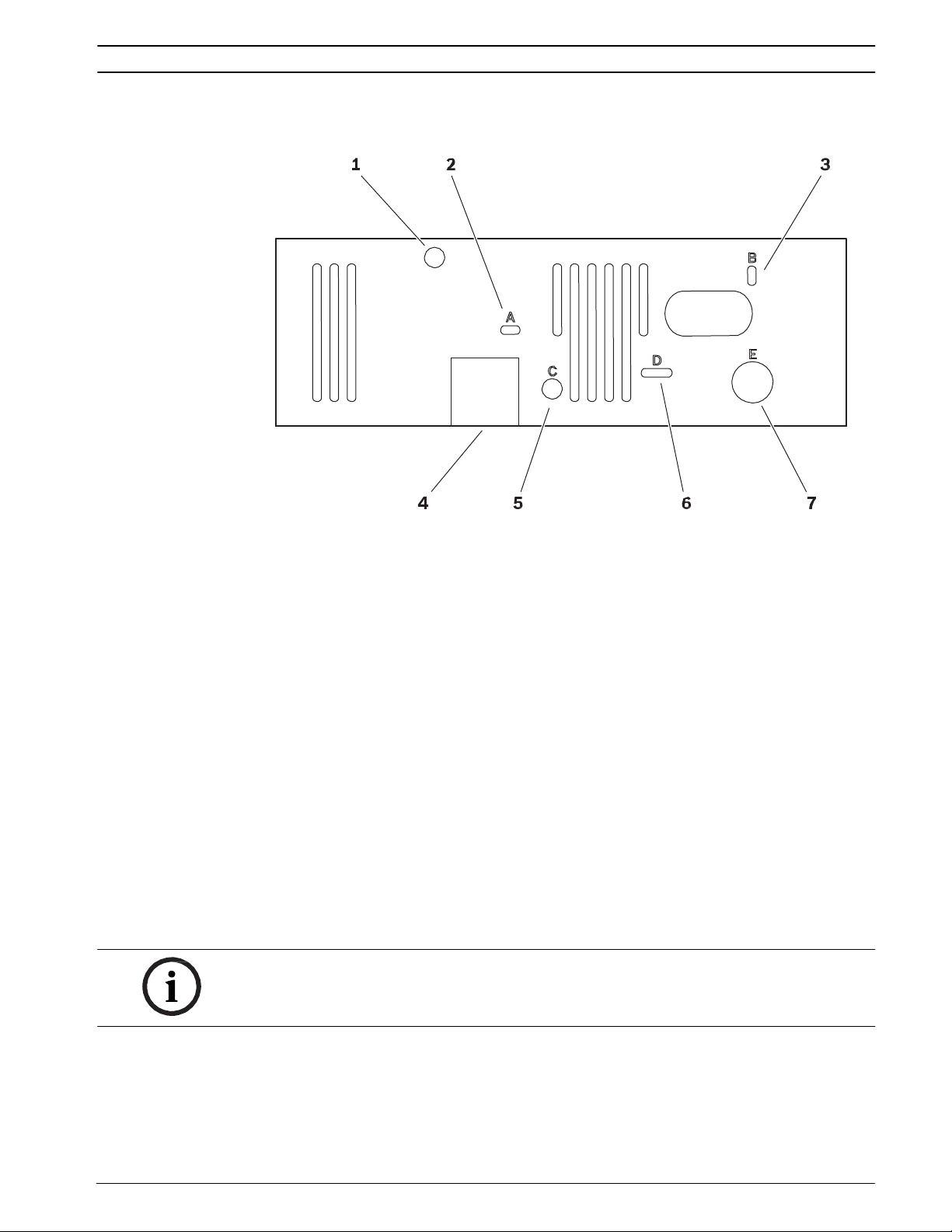
Controls and displays on the camera module
1 Tamper switch
detects every attempt to open the housing
2 Opening A: CONNECT LED
lights up green when ready for operation
3 Opening B: ACT and LINK LEDs
green LED (link): network connection established,
orange LED (activity): data transmission via network connection
4 SD slot
for an SD card
5 Opening C: factory reset button
to restore factory default settings
6 Opening D: LED group D
information on camera and pan/tilt functions
7 Opening E: fuse holder F501
NOTICE!
For more information about the LEDs, see Section 8.4 LEDs, page 97.
Bosch Sicherheitssysteme GmbH Installation and Operating Manual
Doc | V4.6 | 2014.02
Page 16
16 en | Product description
3.5
VOT-320
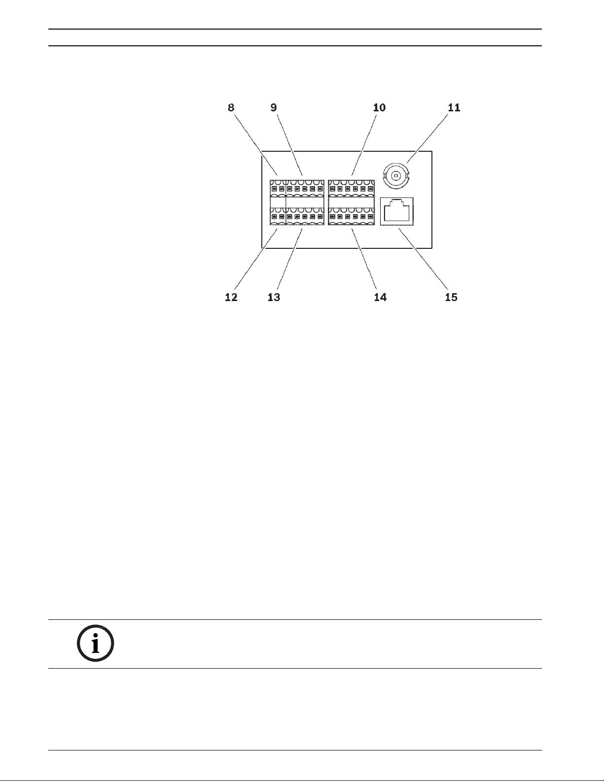
Connections on the camera module
8 Upper 2-pin terminal block
for power supply
9 Upper 5-pin terminal block
for pan/tilt connections
10 Upper 6-pin terminal block
for serial interface connections
11 Video output
BNC socket for connecting a service monitor during camera set-up
12 Lower 2-pin terminal block
for window defroster
13 Lower 5-pin terminal block
for pan/tilt connections
14 Lower 6-pin terminal block
for alarm inputs and relay outputs
15 RJ45 socket
for connecting to an Ethernet LAN (local network), 10/100 MBit Base-T
NOTICE!
For terminal block assignment, see Section 8.8 Terminal blocks, page 99.
Doc | V4.6 | 2014.02 Installation and Operating Manual Bosch Sicherheitssysteme GmbH
Page 17
VOT-320 Installation | en 17
4 Installation
4.1
Preparations
CAUTION!
The camera is intended for indoor and outdoor use.
Select a suitable location for installation that guarantees to meet the environmental
conditions. The ambient temperature must be between -50 and +55 °C (-58 and +131 °F). The
relative humidity must not exceed 93%.
Please ensure the following installation conditions:
– Do not install the unit close to heat sources. Avoid locations exposed to direct sunlight.
– Allow sufficient space for running cables.
– Ensure that the unit has adequate ventilation.
– When making connections, use only the cables supplied or use appropriate cables
immune to electromagnetic interference.
– Ensure to use cables matching the installation location. For example, use cables marked
“Outdoor Cable” or “Water Resistant” for outdoor installation. For the US, cables must
comply with NATIONAL ELECTRICAL CODE, NFPA 70.
– Position and run all cables so that they are protected from damage, and provide
adequate cable strain relief where needed.
– Avoid impacts, blows and severe vibrations that exceed the specification limits (see
Section 9 Specifications, page 104), as these can irreparably damage the unit.
4.2
Mounting
You can mount the camera to mounts or pan/tilts and place it to walls, below ceilings, on roof
tops or poles or any other load-bearing locations.
CAUTION!
The camera must be properly and securely mounted to a supporting structure capable of
sustaining the unit weight. Use care when selecting mounts or pan/tilts (not supplied) for
installation; the mounting surface and unit's weight should be carefully considered.
CAUTION!
If the camera is mounted to a pan/tilt, ensure that your hands do not get caught or crushed
between camera and pan/tilt.
Bosch Sicherheitssysteme GmbH Installation and Operating Manual
Doc | V4.6 | 2014.02
Page 18
18 en | Installation
VOT-320
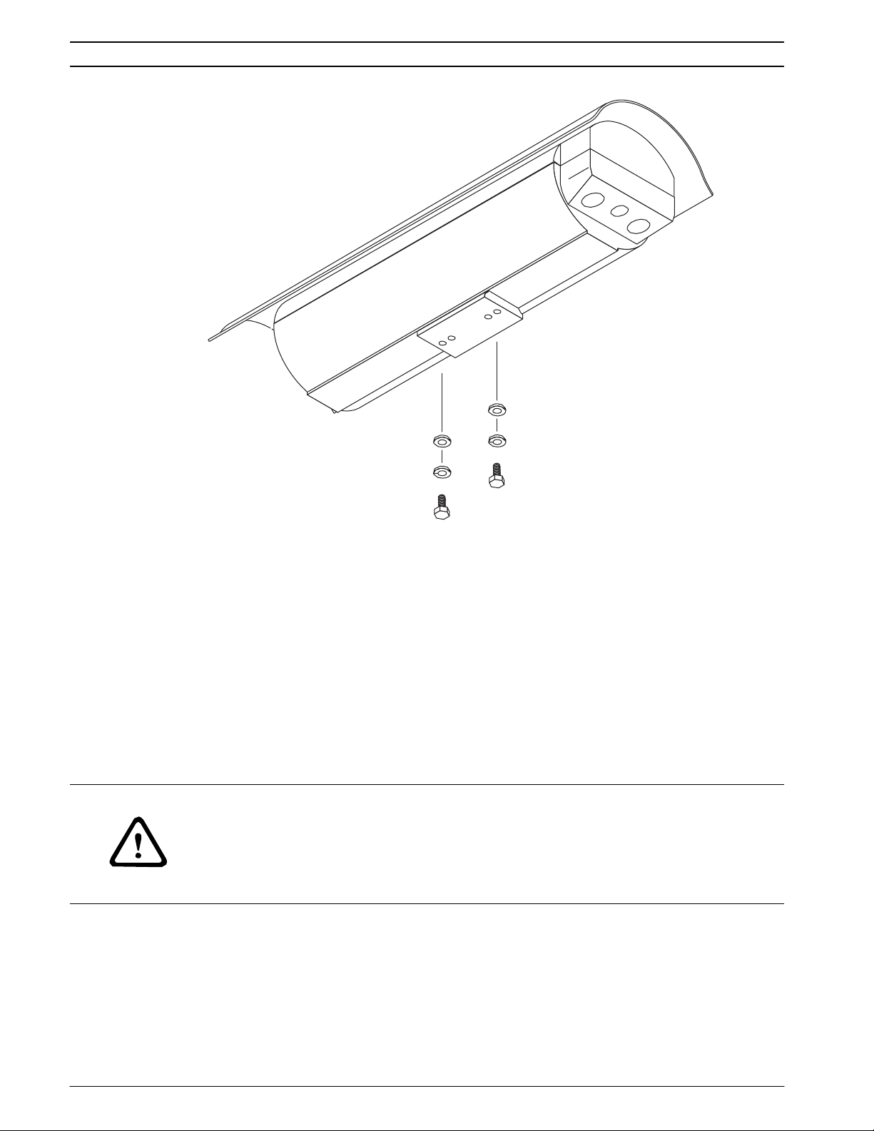
1. Use two appropriate screws, washers and spring washers to mount the camera to a
mount or a pan/tilt. The spring washers must be used for the screws to thread properly.
2. Open the cover by unlatching the three latches on the side of the housing.
3. Choose the appropriate cable glands. The following cable glands are provided:
– 1 × NPT 3/8’’ for cable diameters from 4 to 8 mm
– 1 × NPT 3/8’’ for cable diameters from 2 to 6 mm
– 2 × NPT 1/2’’ for cable diameters from 6 to 12 mm
The identical cable glands are for the outer two openings in the housing. For the middle
opening, choose the NPT 3/8’’ cable gland with the correct diameter for your cabeling to
prevent water from entering.
4. Fasten the required cable glands. Tighten the glands to a torque of at least 1.6 Nm.
5. Run the required cables through the cable glands and close the glands.
CAUTION!
Always securely tighten all cable glands to ensure a liquid-tight seal. Failure to do so could
allow water to enter the housing and damage the camera module and electronic parts. If a
sealant is used, be sure it is a neutral cure type. Sealants that release acetic acid may harm
camera electronics. Use of drip loops is recommended on the wiring outside of the rear end
cap.
Doc | V4.6 | 2014.02 Installation and Operating Manual Bosch Sicherheitssysteme GmbH
Page 19
VOT-320 Installation | en 19
4.3
Connections
Network
You can connect the VOT-320 to a 10/100 Base-T network using a standard UTP category 5
cable with RJ45 plugs.
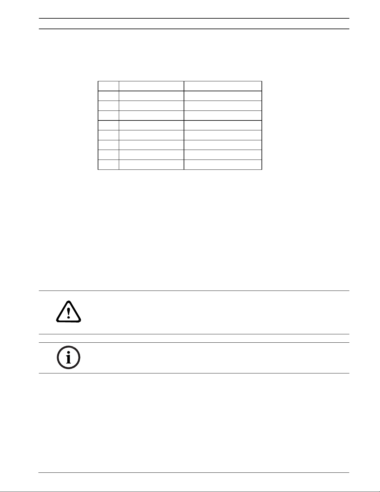
Pin EIA/TIA-568-A EIA/TIA-568-B
1 white/green white/orange
2 green orange
3 white/orange white/green
4 blue blue
5 white/blue white/blue
6 orange green
7 white/brown white/brown
8 brown brown
1. First crimp the wires according to the EIA/TIA standard you are using.
2. Connect the VOT-320 to the network via the RJ45 socket on the back of the camera
module.
Data interface
The bidirectional data interface is used to control units connected to the VOT-320, such as
pan/tilts that are not connected directly to the P/T connections (see Section Pan/tilt
connection, page 20). The connection supports the RS-232, RS-422 and RS-485 transmission
standards.
The VOT-320 offers the serial interface via the upper 6-pin terminal block (see
Section 8.8 Terminal blocks, page 99).
The range of controllable equipment is expanding constantly. The manufacturers of the
relevant equipment provide specific information on installation and control.
CAUTION!
Please take note of the appropriate documentation when installing and operating the unit to
be controlled.
The documentation contains important safety instructions and information about permitted
uses.
NOTICE!
A video connection is necessary to transmit transparent data.
Bosch Sicherheitssysteme GmbH Installation and Operating Manual
Doc | V4.6 | 2014.02
Page 20
20 en | Installation
VOT-320
Pan/tilt connection
The pan/tilt connections are used to control a suitable Bosch pan/tilt.
Other pan/tilts may be controlled via the serial interface (see Section Data interface, page 19).
The connections are located on the two 5-pin terminal blocks (see Section 8.8 Terminal blocks,
page 99).
NOTICE!
The release letter for the current firmware version includes a list of compatible Bosch pan/
tilts.
CAUTION!
Please take note of the appropriate documentation when installing and operating the unit to
be controlled.
The documentation contains important safety instructions and information about permitted
uses.
Alarm inputs
The VOT-320 has two alarm inputs on the lower 6-pin terminal block (see Section 8.8 Terminal
blocks, page 99). The alarm inputs are used to connect to external alarm devices such as door
contacts or sensors. With the appropriate configuration, an alarm sensor can automatically
connect the VOT-320 to a remote location, for example.
A zero potential closing contact or switch can be used as the actuator.
NOTICE!
If possible, use a bounce-free contact system as the actuator.
Connect the lines to the appropriate terminals on the lower 6-pin terminal block (IN1 and
IN2) and check that the connection is secure.
Relay outputs
The VOT-320 has two relay outputs for switching external units such as lamps or alarm sirens.
You can operate these relay outputs manually while there is an active connection to the
VOT-320. The outputs can also be configured to automatically activate sirens or other alarm
units in response to an alarm signal. The relay outputs are also located on the lower 6-pin
terminal block (see Section 8.8 Terminal blocks, page 99).
CAUTION!
A maximum load of 30 V
Connect the lines to the appropriate terminals on the lower 6-pin terminal block (R1 and
R2) and check that the connection is secure.
(SELV) and 200 mA may be applied to the relay contacts.
p-p
Doc | V4.6 | 2014.02 Installation and Operating Manual Bosch Sicherheitssysteme GmbH
Page 21
VOT-320 Installation | en 21
SD slot
You can insert an SD card into the slot on the side of the camera module to enable recordings
to be saved locally. SD cards are the ideal solution for shorter storage times and temporary
recordings, for example alarm recordings or local buffering in the event of network
interruptions.
NOTICE!
The release letter for the current firmware version includes a list of compatible SD cards.
Playing back recordings is also possible using a different VOT-320 camera.
CAUTION!
If the card is formatted, all existing data is deleted from the card.
You should therefore check whether the SD card contains any data that needs to be backed
up before it is inserted.
1. Carefully slide the SD card into the slot as far as it will go, until it locks into place.
2. To remove the SD card, push carefully in the direction of insertion until the mechanical
catch releases and then remove the card.
4.4
Power on/power off
Power supply
The VOT-320 does not have a power switch. Power is supplied via a separate unit. Connect
the VOT-320 to the power supply unit and plug this into the mains. The camera is now ready
for use. The VOT-320 does not come supplied with a power supply unit.
CAUTION!
Use only SELV power supply units with UL approval (power supply unit UPA-2450-50 or
similar is recommended to meet all EMI requirements).
Where necessary, use suitable equipment to ensure that the power supply is free from
interference such as voltage surges, spikes or voltage drops.
Do not connect the VOT-320 to the power supply until all other connections have been made.
1. Plug the terminal block with the PSU cable connected to it into the upper 2-pin socket on
the back of the camera module.
2. Connect the power supply unit to the mains. The VOT-320 is ready for use as soon as the
CONNECT LED changes from a red light, indicating the start-up procedure, to a green
light.
Provided the network connection has been correctly made, the green LINK LED also lights up.
The lit orange ACTIVITY LED signals that data packets are being transmitted via the network.
Bosch Sicherheitssysteme GmbH Installation and Operating Manual
Doc | V4.6 | 2014.02
Page 22
22 en | Installation
4.5
4.6
VOT-320
Adjusting the lens (only WFOV lenses)
Cameras with 9 mm, 13 mm, and 19 mm cover a wide field of view (WFOV). For these lenses
you may need to adjust the camera focus. You connect a service monitor in order to set-up the
camera and adjust the lens. Any monitors that support a standard NTSC signal are suitable.
1. Connect the monitor to the BNC socket on the back of the camera module using a video
cable (75 Ohm, BNC plug).
2. Check the image on the monitor.
3. If the camera focus needs to be adjusted, loosen the four fixing screws of the camera
module.
4. Lift the camera module and slide it backwards in order to reach the lens.
5. Attach the focussing tool to the lens and turn it to set the focus.
6. Remove the focussing tool.
7. Lift the camera module and slide it back to the original position.
8. Refasten the four screws.
9. Disconnect the monitor after set-up.
All other lenses are preset and do not need to be adjusted.
Final assembly
1. Close unused holes with suitable plugs.
2. Close the cover and secure the latches using the tamper resistant screws and the
provided torx wrench.
3. Loosen the two sunshield screws (M4 × 10) on the top of the housing.
4. Slide the sunshield to the desired position. It has a range of 50 mm (2 in).
5. Tighten the screws to lock the sunshade into position.
4.7
Setup using Bosch Video Client
The Bosch Video Client program can be found on the product CD supplied. This program
allows you to implement and set up the camera in the network quickly and conveniently.
NOTICE!
Using Bosch Video Client to set all parameters in the VOT-320 is an alternative to
configuration by means of a Web browser, as described in chapter 5 of this manual.
Installing the program
1. Insert the product disc into the optical drive of the PC;
– The installation program should start automatically.
2. If installation does not start automatically, locate the BVC_installer.exe file on the disk
and double-click it.
3. Follow the instructions on the screen to complete the installation.
Configuring the camera
You can start Bosch Video Client immediately after installation.
1. Double-click the icon on the desktop to start the program. Alternatively, start the
application via the Start button and the Programs menu (path: Start/Programs/Bosch
Video Client/Bosch Video Client).
2. When the program is started for the first time, a wizard opens to help you detect and
configure devices on the network.
Doc | V4.6 | 2014.02 Installation and Operating Manual Bosch Sicherheitssysteme GmbH
Page 23
VOT-320 Installation | en 23
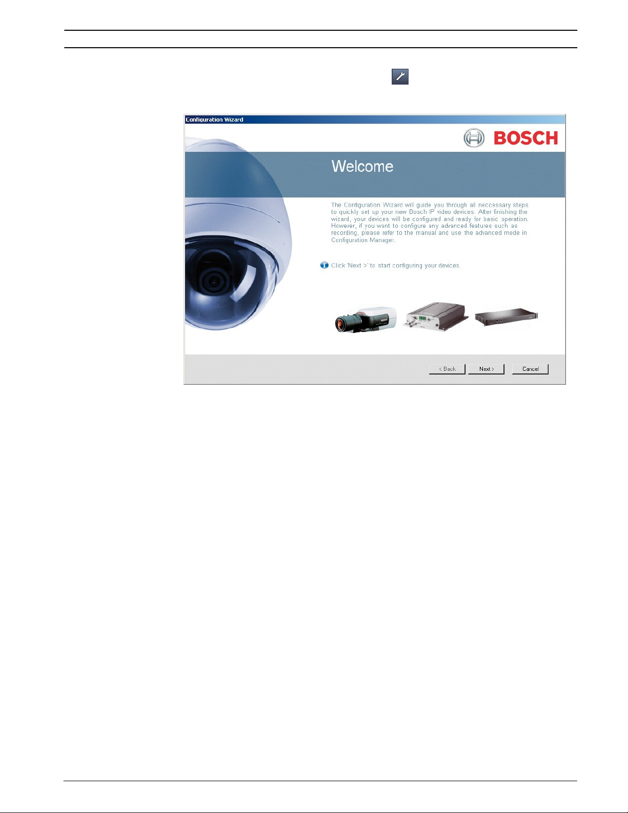
3. If the wizard does not start automatically, click to open the Configuration Manager
application. Then, click Configuration Wizard... on the Tools menu.
4. Follow the instructions given in the Configuration Wizard window.
Additional parameters
You can check and set additional parameters with the assistance of the Configuration
Manager application in Bosch Video Client. You can find detailed information on this in the
documentation for these applications.
Bosch Sicherheitssysteme GmbH Installation and Operating Manual
Doc | V4.6 | 2014.02
Page 24
24 en | Configuration using a Web browser
5 Configuration using a Web browser
5.1
Connecting
The integrated HTTP server in the VOT-320 provides you with the option to configure the
camera over the network with a Web browser. This option is an alternative to configuration
using the Configuration Manager application in Bosch Video Client and is considerably richer
in function and more convenient than configuration using the terminal program.
System requirements
– Computer with Windows XP or Windows Vista operating system
– Network access (Intranet or Internet)
– Microsoft Internet Explorer (version 7.0 or higher)
– Screen resolution at least 1,024 × 768 pixels
– 16- or 32-bit color depth
– Installed Sun JVM
NOTICE!
Also note the information in the System Requirements document on the product CD
supplied. If necessary, you can install the required programs and controls from the product
CD supplied (see Section 3.1 Parts included, page 10).
The Web browser must be configured to enable Cookies to be set from the IP address of the
camera.
In Windows Vista, deactivate protected mode on the Security tab under Internet Options.
You can find notes on using Microsoft Internet Explorer in the online Help in Internet Explorer.
Installing MPEG ActiveX
Suitable MPEG ActiveX software must be installed on the computer to allow the live video
images to be played back. If necessary, you can install the program from the product CD
supplied.
1. Insert the product CD into the computer's CD-ROM drive. If the CD does not start
automatically, open the root directory of the CD in Windows Explorer and double-click
MPEGAx.exe.
2. Follow the on-screen instructions.
VOT-320
Doc | V4.6 | 2014.02 Installation and Operating Manual Bosch Sicherheitssysteme GmbH
Page 25
VOT-320 Configuration using a Web browser | en 25
Establishing the connection
Before you can operate the VOT-320 within your network, it must have a valid IP address for
your network and a compatible subnet mask.
The following default address is preset at the factory: 192.168.0.1
1. Start the Web browser.
2. Enter the IP address of the VOT-320 as the URL.
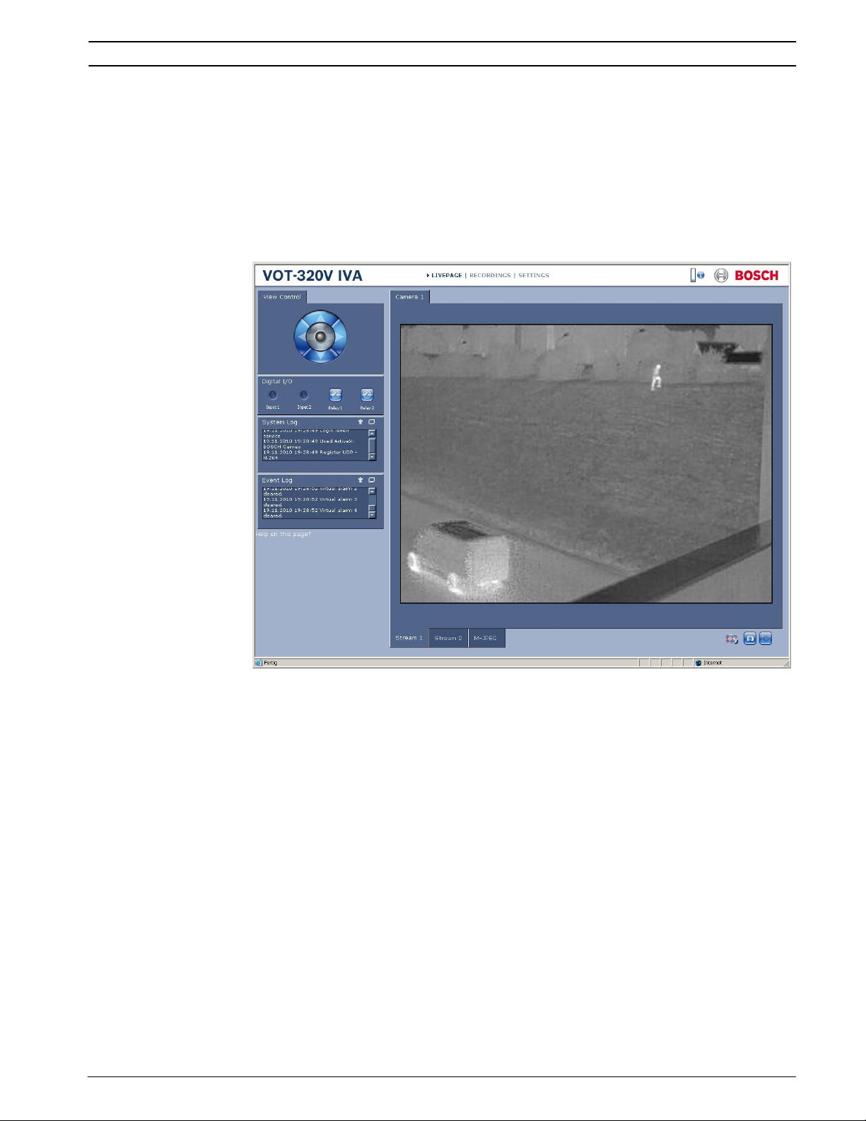
3. During initial installation, confirm the security questions that appear. The connection is
established and after a short time you will see the LIVEPAGE with the video image.
Maximum number of connections
If you do not connect, the camera may have reached its maximum number of connections.
Depending on the unit and network configuration, each VOT-320 can have up to 25 Web
browser connections or up to 50 connections via Bosch Video Client or Bosch Video
Management System.
Bosch Sicherheitssysteme GmbH Installation and Operating Manual
Doc | V4.6 | 2014.02
Page 26
26 en | Configuration using a Web browser
Protected camera
If the VOT-320 is password protected against unauthorized access, the Web browser displays
a corresponding message and prompts you to enter the password when you attempt to
access protected areas.
NOTICE!
The VOT-320 offers the option to limit the extent of access using various authorization levels
(see Section 5.10 Advanced Mode: Password, page 34).
1. Enter the user name and associated password in the corresponding text fields.
2. Click OK. If the password is entered correctly, the Web browser displays the page that
was called up.
Protected network
If a RADIUS server is employed in the network for managing access rights (802.1x
authentication), the VOT-320 must be configured accordingly, otherwise no communication is
possible.
To configure the camera, you must connect the VOT-320 directly to a computer using a
network cable. This is because communication via the network is not enabled until the
Identity and Password parameters have been set and successfully authenticated (see
Section Authentication, page 74).
VOT-320
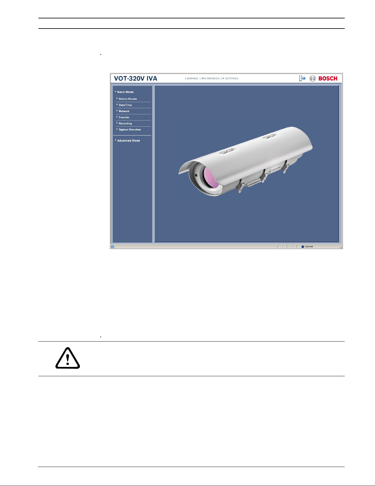
5.2
Configuration menu
The SETTINGS page provides access to the configuration menu, which contains all the
camera's parameters arranged in groups. You can view the current settings by opening one of
the configuration screens. You can change the settings by entering new values or by selecting
a predefined value from a list field.
There are two options for configuring the camera or checking the current settings:
– Basic Mode
– Advanced Mode
In Basic Mode the most important parameters are arranged in seven groups. This allows you
to change the basic settings with just a few entries and then put the device into operation.
Advanced Mode is recommended for expert users or system support personnel. You can
access all device parameters in this mode. Settings that affect the fundamental functionality
of the device (such as firmware updates) can only be altered in Advanced Mode.
All parameter groups are described in this chapter in the order in which they are listed in the
configuration menu, from the top of the screen to the bottom.
CAUTION!
The settings in the Advanced Mode should only be processed or modified by expert users or
system support personnel.
All settings are backed up in the VOT-320 memory so they are not lost even if the power fails.
The exception is the time settings, which are lost after 72 hours without power if no central
time server is selected (see Section 5.4 Basic Mode: Date/Time, page 29).
Doc | V4.6 | 2014.02 Installation and Operating Manual Bosch Sicherheitssysteme GmbH
Page 27
VOT-320 Configuration using a Web browser | en 27
Starting configuration
・
Click the SETTINGS link in the upper section of the window. The Web browser opens a
new page with the configuration menu.
Navigation
1. Click one of the menu items in the left window margin. The corresponding submenu is
displayed.
2. Click one of the entries in the submenu. The Web browser opens the corresponding
page.
Making changes
Each configuration screen shows the current settings. You can change the settings by entering
new values or by selecting a predefined value from a list field.
・
After each change, click Set to save the change.
CAUTION!
Save each change with the associated Set button.
Clicking the Set button saves the settings only in the current field. Changes in any other fields
are ignored.
Bosch Sicherheitssysteme GmbH Installation and Operating Manual
Doc | V4.6 | 2014.02
Page 28
28 en | Configuration using a Web browser
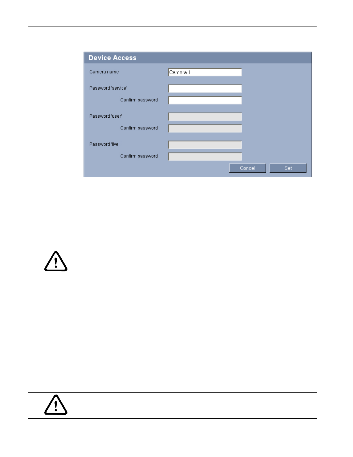
5.3
Basic Mode: Device Access
VOT-320
Camera name
The camera name makes it easier to identify the remote camera location, in the event of an
alarm for example. It will be displayed in the video screen if configured to do so (see
Section Camera name stamping, page 36). The camera name makes the task of administering
cameras in larger video monitoring systems easier, for example using the Bosch Video Client
or Bosch Video Management System programs.
Enter a unique, unambiguous name for the camera in this field.
CAUTION!
Do not use any special characters, for example &, in the name.
Special characters are not supported by the system's internal management.
Password
A VOT-320 is generally protected by a password to prevent unauthorized access to the
camera. You can use different authorization levels to limit access.
The VOT-320 operates with three authorization levels: service, user and live.
The highest authorization level is service. After entering the correct password, you can access
all the functions of the VOT-320 and change all configuration settings.
With the user authorization level, you can operate the camera, play back recordings and also
control cameras, for example, but you cannot change the configuration.
The lowest authorization level is live. It can only be used to view the live video image and
switch between the different live image displays.
You can define and change a password for each authorization level if you are logged in as
service or if the camera is not password protected.
Enter the password for the appropriate authorization level here. The maximum password text
length is 19 characters.
CAUTION!
Do not use any special characters, for example &, in the password.
Special characters are not supported by the system's internal management.
Doc | V4.6 | 2014.02 Installation and Operating Manual Bosch Sicherheitssysteme GmbH
Page 29
VOT-320 Configuration using a Web browser | en 29
NOTICE!
Proper password protection is only guaranteed when all higher authorization levels are also
protected with a password. If a live password is assigned, for example, a service and a user
password must also be set. When assigning passwords, you should therefore always start
from the highest authorization level, service, and use different passwords.
Confirm password
In each case, enter the new password a second time to eliminate typing mistakes.
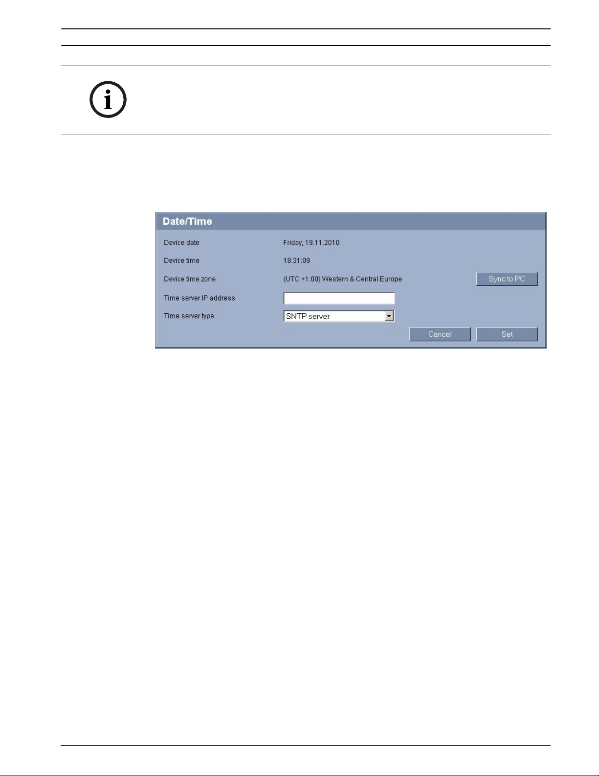
5.4
Basic Mode: Date/Time
Device date / Device time / Device time zone
If there are multiple devices operating in your system or network, it is important to
synchronize their internal clocks. For example, it is only possible to identify and correctly
evaluate simultaneous recordings when all units are operating on the same time. If necessary,
you can synchronize the camera with your computer's system settings.
Click the Sync to PC button to copy your computer's system time to the VOT-320.
Time server IP address
The VOT-320 can receive the time signal from a time server using various time server
protocols, and then use it to set the internal clock. The camera polls the time signal
automatically once every minute.
Enter the IP address of a time server here.
Time server type
Select the protocol that is supported by the selected time server. Preferably, you should
select SNTP server as the protocol. This supports a high level of accuracy and is required for
special applications and subsequent function extensions.
Select Time server for a time server that works with the protocol RFC 868.
Bosch Sicherheitssysteme GmbH Installation and Operating Manual
Doc | V4.6 | 2014.02
Page 30
30 en | Configuration using a Web browser
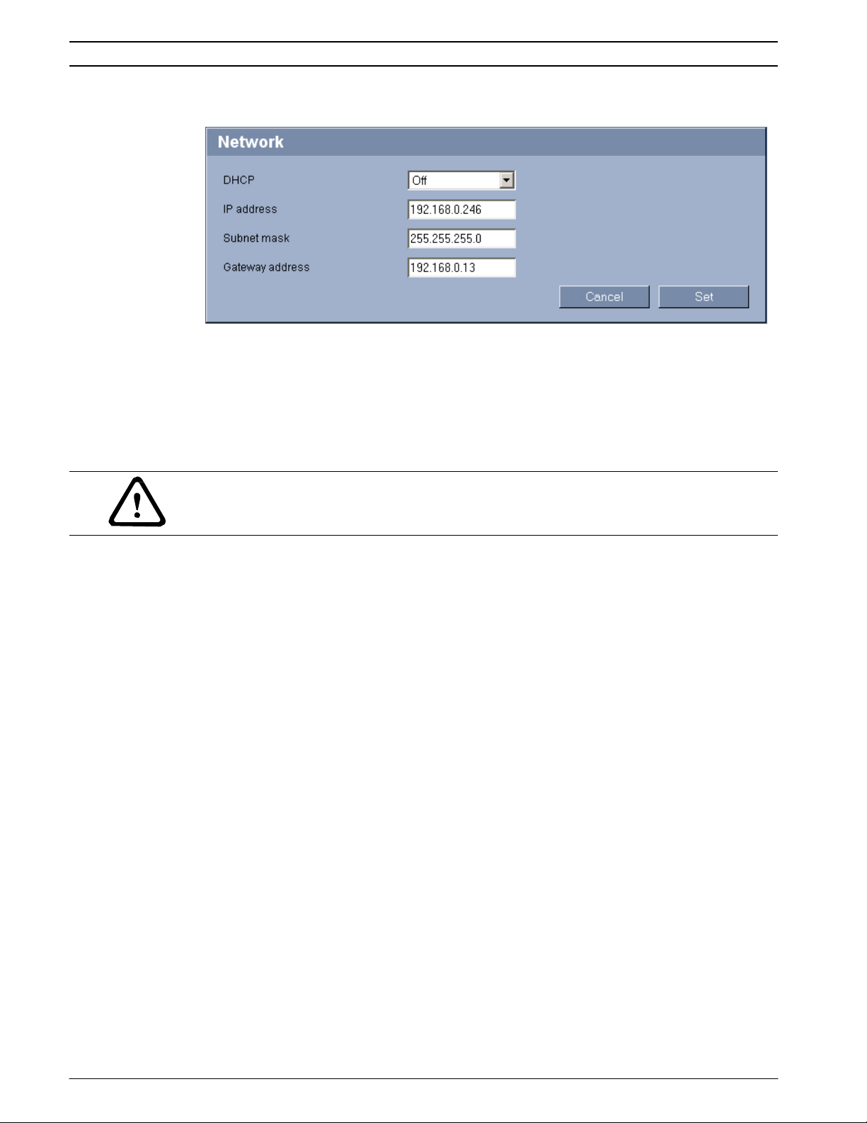
5.5
Basic Mode: Network
VOT-320
The settings on this page are used to integrate the VOT-320 into an existing network.
Some changes only take effect after the camera is rebooted. In this case, the Set button
changes to Set and Reboot.
1. Make the desired changes.
2. Click the Set and Reboot button. The VOT-320 is rebooted and the changed settings are
activated.
CAUTION!
If you change the IP address, subnet mask or gateway address, the VOT-320 is only available
under the new addresses after the reboot.
DHCP
If a DHCP server is employed in the network for the dynamic assignment of IP addresses, you
can activate acceptance of IP addresses automatically assigned to the VOT-320.
Certain applications (Bosch Video Client, Bosch Video Management System) use the IP
address for the unique assignment of the camera. If you use these applications, the DHCP
server must support the fixed assignment between IP address and MAC address, and must be
appropriately set up so that, once an IP address is assigned, it is retained each time the
system is rebooted.
IP address
Enter the desired IP address for the VOT-320 in this field. The IP address must be valid for the
network.
Subnet mask
Enter the appropriate subnet mask for the selected IP address here.
Gateway address
If you want the camera to establish a connection to a remote location in a different subnet,
enter the IP address of the gateway here. Otherwise leave the box blank (0.0.0.0).
Doc | V4.6 | 2014.02 Installation and Operating Manual Bosch Sicherheitssysteme GmbH
Page 31

VOT-320 Configuration using a Web browser | en 31
5.6
Basic Mode: Encoder
Non-recording profile
You can select a profile for encoding the video signal.
You can use this to adapt the video data transmission to the operating environment (for
example network structure, bandwidth, data load).
Pre-programmed profiles are available, each giving priority to different perspectives. When
selecting a profile, details are displayed in the list field. Below is a brief description of the
factory default settings for the encoder profiles.
NOTICE!
The names and the technical details for the encoder profiles depend on the configuration of
the device.
– High quality 1
For high bandwidth connections with IBBP GOP structure
– High quality 2
For high bandwidth connections with IP GOP structure
– Low bandwidth
For low bandwidth connections with lP GOP structure
– DSL
For DSL connections with 500 kbps
– ISDN (2B)
For ISDN connections via two B-channels
– ISDN (1B)
For ISDN connections via one B-channel
– MODEM
For analog modem connections with 20 kbps
– GSM
For GSM connections at 9,600 baud
Bosch Sicherheitssysteme GmbH Installation and Operating Manual
Doc | V4.6 | 2014.02
Page 32

32 en | Configuration using a Web browser
5.7
Basic Mode: Recording
VOT-320
5.8
You can record the images from the camera on the local SD card. SD cards are the ideal
solution for shorter storage times. Here you can start or stop the recording.
Basic Mode: System Overview
The data on this page are for information purposes only and cannot be changed. Keep a
record of these numbers in case technical assistance is required.
NOTICE!
You can select all required text on this page with the mouse and copy it to the clipboard with
the [Ctrl]+[C] key combination, for example if you want to send it via e-mail.
Doc | V4.6 | 2014.02 Installation and Operating Manual Bosch Sicherheitssysteme GmbH
Page 33

VOT-320 Configuration using a Web browser | en 33
5.9
Advanced Mode: Identification
Camera ID
Each VOT-320 should be assigned a unique identifier that you can enter here as an additional
means of identification.
Camera name
The camera name makes it easier to identify the remote camera location, in the event of an
alarm for example. It will be displayed in the video screen if configured to do so (see
Section Camera name stamping, page 36). The camera name makes the task of administering
cameras in larger video monitoring systems easier, for example using the Bosch Video Client
or Bosch Video Management System programs.
Enter a unique, unambiguous name for the camera in this field. You can use both lines for this.
CAUTION!
Do not use any special characters, for example &, in the name.
Special characters are not supported by the system's internal management.
You can use the second line for entering additional characters; these can be selected from a
table.
1. Click the icon next to the second line. A new window with the character map is opened.
2. Click the required character. The character is inserted into the Result field.
3. In the character map, click the << and >> icons to move between the different pages of
the table, or select a page from the list field.
4. Click the < icon to the right of the Result field to delete the last character, or click the X
icon to delete all characters.
5. Now click the OK button to apply the selected characters to the second line of the
Camera 1 parameters. The window will close.
Initiator extension
You can attach your own text to the initiator name of the VOT-320 to make the camera easier
to identify in large iSCSI systems. This text is added to the initiator name, separated from it by
a full stop. You can see the initiator name in the system overview (see Section 5.8 Basic Mode:
System Overview, page 32).
Bosch Sicherheitssysteme GmbH Installation and Operating Manual
Doc | V4.6 | 2014.02
Page 34

34 en | Configuration using a Web browser
5.10
Advanced Mode: Password
VOT-320
A VOT-320 is generally protected by a password to prevent unauthorized access to the
camera. You can use different authorization levels to limit access.
NOTICE!
Proper password protection is only guaranteed when all higher authorization levels are also
protected with a password. If a live password is assigned, for example, a service and a user
password must also be set. When assigning passwords, you should therefore always start
from the highest authorization level, service, and use different passwords.
Password
The VOT-320 operates with three authorization levels: service, user and live.
The highest authorization level is service. After entering the correct password, you can access
all the functions of the VOT-320 and change all configuration settings.
With the user authorization level, you can operate the camera, play back recordings and also
control cameras, for example, but you cannot change the configuration.
The lowest authorization level is live. It can only be used to view the live video image and
switch between the different live image displays.
You can define and change a password for each authorization level if you are logged in as
service or if the camera is not password protected.
Enter the password for the appropriate authorization level here. The maximum password text
length is 19 characters.
CAUTION!
Do not use any special characters, for example &, in the password.
Special characters are not supported by the system's internal management.
Confirm password
In each case, enter the new password a second time to eliminate typing mistakes.
Doc | V4.6 | 2014.02 Installation and Operating Manual Bosch Sicherheitssysteme GmbH
Page 35

VOT-320 Configuration using a Web browser | en 35
5.11
Advanced Mode: Date/Time
Date format
Select your required date format.
Device date / Device time
If there are multiple devices operating in your system or network, it is important to
synchronize their internal clocks. For example, it is only possible to identify and correctly
evaluate simultaneous recordings when all units are operating on the same time.
1. Enter the current date. Since the camera time is controlled by the internal clock, there is
no need to enter the day of the week – it is added automatically.
2. Enter the current time or click the Sync to PC button to copy your computer's system
time to the VOT-320.
Device time zone
Select the time zone in which your system is located.
Daylight saving time
The internal clock can switch automatically between normal and daylight saving time (DST).
The camera already contains the data for DST switch-overs up to the year 2018. You can use
these data or create alternative time saving data if required.
NOTICE!
If you do not create a table, there will be no automatic switching. When changing and clearing
individual entries, remember that two entries are usually related to each other and dependent
on one another (switching to summer time and back to normal time).
1. First check whether the correct time zone is selected. If it is not correct, select the
appropriate time zone for the system, and click the Set button.
2. Click the Details button. A new window will open and you will see the empty table.
3. Select the region or the city that is closest to the system's location from the list field
below the table.
4. Click the Generate button to generate data and enter it into the table.
5. Make changes by clicking an entry in the table. The entry is selected.
6. Clicking the Delete button will remove the entry from the table.
7. Select other values from the list fields below the table to change the entry. Changes are
made immediately.
Bosch Sicherheitssysteme GmbH Installation and Operating Manual
Doc | V4.6 | 2014.02
Page 36

36 en | Configuration using a Web browser
8. If there are empty lines at the bottom of the table, for example after deletions, you can
add new data by marking the row and selecting required values from the list fields.
9. Now click the OK button to apply and activate the table.
Time server IP address
The VOT-320 can receive the time signal from a time server using various time server
protocols, and then use it to set the internal clock. The camera polls the time signal
automatically once every minute.
Enter the IP address of a time server here.
Time server type
Select the protocol that is supported by the selected time server. Preferably, you should
select SNTP server as the protocol. This supports a high level of accuracy and is required for
special applications and subsequent function extensions.
Select Time server for a time server that works with the protocol RFC 868.
5.12
Advanced Mode: Display Stamping
VOT-320
Various overlays or "stamps" in the video image provide important supplementary information.
These overlays can be enabled individually and are arranged on the image in a clear manner.
Camera name stamping
This field sets the position of the camera name overlay. It can be displayed at the Top, at the
Bottom, or at a position of your choice that you can then specify using the Custom option. Or
it can be set to Off for no overlay information.
1. Select the desired option from the list.
2. If you select the Custom option, additional fields are displayed where you can specify the
exact position (Position (XY)).
3. In the Position (XY) fields, enter the values for the desired position.
Time stamping
This field sets the position of the time overlay. It can be displayed at the Top, at the Bottom,
or at a position of your choice that you can then specify using the Custom option. Or it can be
set to Off for no overlay information.
1. Select the desired option from the list.
2. If you select the Custom option, additional fields are displayed where you can specify the
exact position (Position (XY)).
3. In the Position (XY) fields, enter the values for the desired position.
Doc | V4.6 | 2014.02 Installation and Operating Manual Bosch Sicherheitssysteme GmbH
Page 37

VOT-320 Configuration using a Web browser | en 37
Display milliseconds
You can only select this option if the Time stamping function is activated. If necessary, you
can also display milliseconds. This information can be useful for recorded video images;
however, it does increase the processor's computing time. Select Off if you do not need to
display milliseconds.
Alarm mode stamping
Select On to display a text message overlay in the image in the event of an alarm. It can be
displayed at a position of your choice that you can then specify using the Custom option. Or it
can be set to Off for no overlay information.
1. Select the desired option from the list.
2. If you select the Custom option, additional fields are displayed where you can specify the
exact position (Position (XY)).
3. In the Position (XY) fields, enter the values for the desired position.
Alarm message
Enter the message to be displayed in the image in the event of an alarm. The maximum text
length is 31 characters.
Video watermarking
Choose On if you wish the transmitted video images to be "watermarked". After activation, all
images are marked with an icon. The icon indicates if the sequence (live or saved) has been
manipulated (see Section Display stamping, page 84).
5.13
Advanced Mode: Appearance
On this page you can adapt the appearance of the web interface and change the website
language to meet your requirements. If necessary, you can replace the manufacturer's logo
(top right) and the product name (top left) in the top part of the window with individual
graphics.
NOTICE!
You can use either GIF or JPEG images. The file paths must correspond to the access mode
(for example C:\Images\Logo.gif for access to local files, or
http://www.mycompany.com/images/logo.gif for access via the Internet/Intranet).
When accessing via the Internet/Intranet, ensure that a connection is always available to
display the image. The image file is not stored in the VOT-320.
Website language
Select the language for the user interface here.
Bosch Sicherheitssysteme GmbH Installation and Operating Manual
Doc | V4.6 | 2014.02
Page 38

38 en | Configuration using a Web browser
Company logo
Enter the path to a suitable graphic if you want to replace the manufacturer's logo. The image
file can be stored on a local computer, in the local network or at an Internet address.
Device logo
Enter the path to a suitable graphic if you want to replace the product name. The image file
can be stored on a local computer, in the local network or at an Internet address.
NOTICE!
If you want to use the original graphics again, simply delete the entries in the Company logo
and Device logo fields.
JPEG interval
You can specify the interval at which the individual images should be generated for the MJPEG image on the LIVEPAGE.
5.14
Advanced Mode: LIVEPAGE Functions
VOT-320
On this page you can adapt the LIVEPAGE functions to your requirements. You can choose
from a variety of different options for displaying information and controls.
1. Check the box for the items that are to be made available on the LIVEPAGE. The selected
items are indicated by a check mark.
Doc | V4.6 | 2014.02 Installation and Operating Manual Bosch Sicherheitssysteme GmbH
2. Check whether the required functions are available on the LIVEPAGE.
Show alarm inputs
Alarm inputs are shown next to the video image as icons, along with their assigned names. If
an alarm is active, the corresponding icon changes color.
Show relay outputs
Relay outputs are shown next to the video image as icons, along with their assigned names. If
the relay is switched, the icon changes color.
Page 39

VOT-320 Configuration using a Web browser | en 39
Show VCA trajectories
The trajectories (motion lines of objects) from the video content analysis are displayed in the
live video image if a corresponding analysis type is activated (see Section 5.28 Advanced Mode:
VCA Event triggered, page 62).
Show VCA metadata
When the analysis function is activated, the additional information from the video content
analysis (VCA) will be displayed in the live video image (see Section 5.28 Advanced Mode: VCA
Event triggered, page 62). With the MOTION+ analysis type, for example, the sensor fields in
which motion is recorded will be marked with rectangles.
Show event log
The event messages are displayed along with the date and time in a field next to the video
image.
Show system log
The system messages are displayed along with the date and time in a field next to the video
image and provide information about establishing and ending connections, for example.
Allow snapshots
Here you can specify whether the icon for saving individual images should be displayed below
the live image. Individual images can only be saved if this icon is visible.
Allow local recording
Here you can specify whether the icon for saving video sequences on the local memory should
be displayed below the live image. Video sequences can only be saved if this icon is visible.
Path for JPEG and video files
1. Enter the path for the storage location of individual images and video sequences that you
can save from the LIVEPAGE.
2. If necessary, click Browse to find a suitable directory.
5.15
Advanced Mode: Logging
Save event log
Check this option to save event messages in a text file on your local computer.
You can then view, edit and print this file with any text editor or the standard Office software.
File for event log
1. Enter the path for saving the event log here.
2. If necessary, click Browse to find a suitable directory.
Save system log
Check this option to save system messages in a text file on your local computer.
Bosch Sicherheitssysteme GmbH Installation and Operating Manual
Doc | V4.6 | 2014.02
Page 40

40 en | Configuration using a Web browser
You can then view, edit and print this file with any text editor or the standard Office software.
File for system log
1. Enter the path for saving the system log here.
2. If necessary, click Browse to find a suitable directory.
5.16
Advanced Mode: Picture Settings
VOT-320
5.17
You can set the polarity of the thermal image of the camera to suit your requirements. The
current video image is displayed in the small window next to the radio buttons as
confirmation. Your changes are effective immediately.
1. Select the required polarity.
2. Click View Control... under the video window to control the camera when mounted on a
pan/tilt.
Advanced Mode: Encoder Profile
You can change the names and individual parameter values for the encoder profiles.
You can use this to adapt the video data transmission to the operating environment (for
example network structure, bandwidth, data load).
Doc | V4.6 | 2014.02 Installation and Operating Manual Bosch Sicherheitssysteme GmbH
Page 41

VOT-320 Configuration using a Web browser | en 41
Pre-programmed profiles are available, each giving priority to different perspectives. Below is
a brief description of the factory default settings for the encoder profiles.
– High quality 1
For high bandwidth connections with IBBP GOP structure
– High quality 2
For high bandwidth connections with IP GOP structure
– Low bandwidth
For low bandwidth connections with lP GOP structure
– DSL
For DSL connections with 500 kbps
– ISDN (2B)
For ISDN connections via two B-channels
– ISDN (1B)
For ISDN connections via one B-channel
– MODEM
For analog modem connections with 20 kbps
– GSM
For GSM connections at 9,600 baud
CAUTION!
Change the profiles only once you are fully familiar with all the configuration options.
In the default setting, Stream 1 is transmitted for alarm connections and automatic
connections. Bear this fact in mind when assigning the profile.
NOTICE!
All parameters combine to make up a profile and are dependent on one another. If you enter a
setting that is outside the permitted range for a particular parameter, the nearest permitted
value will be substituted when the settings are saved.
Profile name
You can enter a new name for the profile. The name is then displayed in the Non-recording
profile list field on the Encoder Streams page in the lists of selectable profiles.
CAUTION!
Do not use any special characters, for example &, in the name.
Special characters are not supported by the system's internal management.
Target bit rate
You can limit the bit rate for the VOT-320 to optimize utilization of the bandwidth in your
network. The target bit rate should be set according to the desired picture quality for typical
scenes with no excessive motion.
For complex images or frequent changes of image content due to frequent movements, this
limit can be temporarily exceeded up to the value entered in the Maximum bit rate field.
Maximum bit rate
This maximum bit rate is not exceeded under any circumstances. Depending on the video
quality settings for the I and P-frames, this fact can result in individual images being skipped.
The value entered here must be at least 10% higher than the value entered in the Target bit
rate field. If the value entered here is too low, it will automatically be adjusted.
Bosch Sicherheitssysteme GmbH Installation and Operating Manual
Doc | V4.6 | 2014.02
Page 42

42 en | Configuration using a Web browser
Encoding interval
The setting selected here determines the interval at which images are encoded and
transmitted. The image rate in ips (images per second) is displayed next to the text field.
Video resolution
Here you can select the desired resolution for the video image. At present only the following
resolution is available:
– QVGA
320 × 240 pixels
Expert Settings
You can use the expert settings to adapt the I-frame quality and the P-frame quality to specific
requirements, if necessary. The setting is based on the H.264 quantization parameter (QP).
GOP structure
Select the structure you require for the Group of Pictures here. Depending on whether you
place greater priority on having the lowest possible delay (IP frames only) or using as little
bandwidth as possible, you can choose between IP, IBP, and IBBP.
I-frame distance
This parameter allows you to set the intervals in which the I-frames will be coded. With the
Auto setting, the encoder inserts I-frames as necessary. An entry of 3 indicates that only every
third image is an I-frame; the frames in between are coded as P-frames.
I-frame quality
This setting sets the image quality of the I-frames. Select Auto to ensure that the maximum bit
rate is not exceeded. Auto automatically follows the P-frame image quality.
P-frame quality
This setting adjusts the maximum image quality of the P-frames. Auto automatically adjusts to
the optimum combination of movement and image definition (focus).
The value 9 represents maximum image quality, a value of 51 represents minimum quality.
With the slide control, define a control range from a chosen value to 51. The encoder delivers
the best possible quality within this control range while maintaining the maximum bit rate.
Default
Click Default to return the profile to the factory default values.
VOT-320
Doc | V4.6 | 2014.02 Installation and Operating Manual Bosch Sicherheitssysteme GmbH
Page 43

VOT-320 Configuration using a Web browser | en 43
5.18
Advanced Mode: Encoder Streams
The VOT-320 simultaneously generates two H.264 data streams (Dual Streaming); you can
select the relevant property for these here and connect them to an encoder profile, for
example one for transmissions to the Internet and one for LAN connections.
Two settings with different encoder properties are available:
– H.264 BP+ bit-rate-limited
Select this setting when using hardware decoders or the Divar XF digital video recorder.
The bit rate is limited to 1.2 Mbps.
CABAC: off
CAVLC: on
GOP structure: IP
I-frame distance: 15
Deblocking filter: on
– H.264 MP SD
Select this setting when using software decoders, PT and for rapid movements in the
images.
CABAC: on
CAVLC: off
GOP structure: IP
I-frame distance: 30
Deblocking filter: on
CAUTION!
Hardware decoders VIP XD and VIP X1600 XFMD can only process algorithm H.264 BP+. Bear
this in mind when configuring profile settings.
1. Select the required encoder properties and one of the encoder profiles for each data
stream.
2. Click the Preview button. The preview screens for both data streams are shown.
Bosch Sicherheitssysteme GmbH Installation and Operating Manual
Doc | V4.6 | 2014.02
Page 44

44 en | Configuration using a Web browser
3. Click the 1:1 Live View button below the preview screen to open a new window with the
original data stream and to check the image quality and the transmission rate.
Property
Select the required encoder properties for the relevant data stream here.
Non-recording profile
Select the required encoder profile here. The properties of the profiles are defined on the
Encoder Profile page (see Section 5.17 Advanced Mode: Encoder Profile, page 40).
JPEG stream
You can set up the separate JPEG stream in this area. These settings are independent of the
H.264 settings. The resolution corresponds to the highest setting from the two data streams.
Max. frame rate
You can select the maximum frame rate for transmitting the JPEG images.
Picture quality
This setting allows you to define the picture quality. Low quality requires a lower bandwidth
in the network.
VOT-320
Doc | V4.6 | 2014.02 Installation and Operating Manual Bosch Sicherheitssysteme GmbH
Page 45

VOT-320 Configuration using a Web browser | en 45
5.19
Advanced Mode: Storage Management
You can record the images from the camera on the local SD card or on an appropriately
configured iSCSI system.
SD cards are the ideal solution for shorter storage times and temporary recordings, for
example alarm recordings or local buffering in the event of network interruptions.
For long-term, authoritative images, it is essential that you use an appropriately sized iSCSI
system.
It is also possible to let the VRM Video Recording Manager control all recording when
accessing an iSCSI system. This is an external program for configuring recording tasks for
videos. For further information please contact your local customer service at Bosch Security
Systems.
Device manager
If you activate the VRM option in this screen, the VRM Video Recording Manager will manage
all recording and you will not be able to configure any further settings here.
CAUTION!
Activating or deactivating VRM causes the current settings to be lost; they can only be
restored through reconfiguration.
Bosch Sicherheitssysteme GmbH Installation and Operating Manual
Doc | V4.6 | 2014.02
Page 46

46 en | Configuration using a Web browser
Recording media
Select the required recording media here so that you can then activate them and configure
the recording parameters.
iSCSI Media
If you want to use an iSCSI system as a recording medium, you must set up a connection to
the required iSCSI system and set the configuration parameters.
NOTICE!
The iSCSI storage system selected must be available on the network and completely set up.
Amongst other things, it must have an IP address and be divided into logical drives (LUN).
1. Enter the IP address of the required iSCSI target in the iSCSI IP address field.
2. If the iSCSI target is password protected, enter this into the Password field.
3. Click the Read button. The connection to the IP address will be established. In the
Storage overview field, you can see the corresponding logical drives.
Local Media
The supported local recording media are displayed in the Storage overview field.
Activating and configuring storage media
The storage overview displays the available storage media. You can select individual media or
iSCSI drives and transfer these to the Managed storage media list. You can activate the
storage media in this list and configure them for storage.
VOT-320
CAUTION!
Each storage medium can only be associated with one user. If a storage medium is already
being used by another user, you can decouple the user and connect the drive with the
VOT-320. Before decoupling, make absolutely sure that the previous user no longer needs the
storage medium.
1. In the Recording media section, click the iSCSI Media and Local Media tabs to display
the applicable storage media in the overview.
2. In the Storage overview section, double-click the required storage medium, an iSCSI
LUN or one of the other available drives. The medium is then added to the Managed
storage media list. In the Status column, newly added media are indicated by the status
Not active.
3. Click the Set button to activate all media in the Managed storage media list. In the
Status column, these are indicated by the status Online.
4. Check the box in the Rec. 1 or Rec. 2 column to specify which data stream should be
recorded on the storage media selected. Rec. 1 stores Stream 1, Rec. 2 stores Stream 2.
This means that you can record the standard data stream on a hard drive and record
alarm images on the local SD card, for example.
5. Check the boxes for the Overwrite older recordings option to specify which older
recordings can be overwritten once all the available memory capacity has been used.
Recording 1 corresponds to Stream 1, Recording 2 corresponds to Stream 2.
CAUTION!
If older recordings are not allowed to be overwritten when the available memory capacity has
been used, the recording in question will be stopped. You can specify limitations for
overwriting old recordings by configuring the retention time (see Section 5.21 Advanced Mode:
Retention Time, page 50).
Doc | V4.6 | 2014.02 Installation and Operating Manual Bosch Sicherheitssysteme GmbH
Page 47

VOT-320 Configuration using a Web browser | en 47
Formatting storage media
You can delete all recordings on a storage medium at any time.
CAUTION!
Check the recordings before deleting and back up important sequences on the computer's
hard drive.
1. Click a storage medium in the Managed storage media list to select it.
2. Click the Edit button below the list. A new window will open.
3. Click the Formatting button to delete all recordings in the storage medium.
4. Click OK to close the window.
Deactivating storage media
You can deactivate any storage medium from the Managed storage media list. It is then no
longer used for recordings.
1. Click a storage medium in the Managed storage media list to select it.
2. Click the Remove button below the list. The storage medium is deactivated and removed
from the list.
Bosch Sicherheitssysteme GmbH Installation and Operating Manual
Doc | V4.6 | 2014.02
Page 48

48 en | Configuration using a Web browser
5.20
Advanced Mode: Recording Profiles
VOT-320
You can define up to ten different recording profiles. You will then use these recording
profiles in the recording scheduler, where they are linked with the individual days and times
(see Section 5.22 Advanced Mode: Recording Scheduler, page 51).
NOTICE!
You can change or add to the recording profile description on the tabs on the Recording
Scheduler page (see Section Time periods, page 52).
1. Click one of the tabs to edit the corresponding profile.
2. If necessary, click the Default button to return all settings to their default values.
3. Click the Copy Settings button if you want to copy the currently visible settings to other
profiles. A new window will open and you can select the profiles in which you want to
copy the settings.
4. For each profile, click the Set button to save the settings in the camera.
Stream profile settings
You can select the profile setting that is to be used for each data stream in the event of
recordings. This selection is independent of the selection for live data stream transmission
(see Section 5.18 Advanced Mode: Encoder Streams, page 43).
The properties of the profiles are defined on the Encoder Profile page (see
Section 5.17 Advanced Mode: Encoder Profile, page 40).
Doc | V4.6 | 2014.02 Installation and Operating Manual Bosch Sicherheitssysteme GmbH
Page 49

VOT-320 Configuration using a Web browser | en 49
Settings for selected streams
The settings in this settings group only refer to the streams selected in the list field. You can
select both streams.
Recording includes
You can specify whether, in addition to video data, metadata (for example alarms, VCA data
and serial data) should also be recorded. Including metadata could make subsequent
searches of recordings easier but it requires additional memory capacity.
CAUTION!
Without metadata, it is not possible to include video content analysis in recordings.
Standard recording
Here you can select the mode for standard recordings.
If you select Continuous, the recording proceeds continuously. If the maximum memory
capacity is reached, older recordings will automatically be overwritten. If you select the Pre-
alarm option, the unit uses a special recording mode for optimal usage of storage capacity: As
soon as a time window for alarm recording begins, recording takes place continuously on one
segment that corresponds in size to a complete alarm sequence (pre- and post-alarm time).
This segment functions in a similar manner to a ring buffer and is overwritten until an alarm is
actually triggered. Then, recording occurs on the segment only for the duration of the preset
post-alarm time and a new segment is subsequently used in the same manner.
If you select Off, no automatic recording takes place.
CAUTION!
You can specify limitations for overwriting older recordings in Continuous mode by
configuring the retention time (see Section 5.21 Advanced Mode: Retention Time, page 50).
Stream
Here you can select the data stream that is to be used for standard recordings. You can select
the data stream for alarm recordings separately and independently of this (see Section Alarm
stream, page 49).
Pre-alarm time
You can select the required pre-alarm time from the list field. This parameter is only
accessible if you have selected the Pre-alarm option under Standard recording.
Post-alarm time
You can select the required post-alarm time from the list field.
Alarm stream
Here you can select the data stream that is to be used for alarm recordings. You can select the
data stream for standard recordings separately and independently of this (see
Section Stream, page 49).
with encoding interval from profile
You can select an alternative encoding interval for the data stream for alarm recordings.
Otherwise the encoding interval of the selected encoder profile is used (see
Section 5.17 Advanced Mode: Encoder Profile, page 40).
Bosch Sicherheitssysteme GmbH Installation and Operating Manual
Doc | V4.6 | 2014.02
Page 50

50 en | Configuration using a Web browser
Export to FTP
Select this parameter if you want all alarm recordings to be exported to an FTP server
automatically. Make sure to have inserted all relevant data for FTP posting (see
Section 5.37 Advanced Mode: FTP Posting, page 76).
Alarm input / Motion/Audio alarm / Video loss alarm
Here you can select the alarm sensor that is to trigger a recording.
NOTICE!
The alarm inputs are configured and activated on the Alarm Inputs page (see
Section 5.31 Advanced Mode: Alarm Inputs, page 66).
The numbering of the checkboxes for the alarm inputs corresponds to the labeling of the
alarm inputs on the VOT-320.
The motion alarm is configured and activated on the VCA page (see Section 5.25 Advanced
Mode: VCA, page 56 onwards).
Virtual alarm
Here you can select the virtual alarm sensors that are to trigger a recording, via RCP+
commands or alarm scripts, for example.
NOTICE!
For more information, please see the Alarm Task Script Language document and the RCP+
documentation. These documents can be found on the product CD supplied.
VOT-320
5.21
Advanced Mode: Retention Time
You can specify the retention times for recordings. If the available memory capacity of a
medium has been used, older recordings are only overwritten if the retention time entered
here has expired.
NOTICE!
Make sure that the retention time corresponds with the available memory capacity. A rule of
thumb for the memory requirement is as follows: 1 GB per hour retention time with 4CIF for
complete frame rate and high image quality.
Recording 1 / Recording 2
Enter the required retention time in hours or days for each recording. Recording 1
corresponds to Stream 1, Recording 2 corresponds to Stream 2.
Doc | V4.6 | 2014.02 Installation and Operating Manual Bosch Sicherheitssysteme GmbH
Page 51

VOT-320 Configuration using a Web browser | en 51
5.22
Advanced Mode: Recording Scheduler
The recording scheduler allows you to link the created recording profiles with the days and
times at which the camera's images are to be recorded in the event of an alarm.
You can link any number of 15-minute intervals with the recording profiles for each day of the
week. Moving the mouse cursor over the table displays the time below it. This aids
orientation.
In addition to the normal weekdays, you can define holidays that are not in the standard
weekly schedule on which recordings are to apply. This allows you to apply a schedule for
Sundays to other days with dates that fall on varying weekdays.
1. Click the profile you want to link in the Time periods field.
2. Click in a field in the table, hold down the mouse button and drag the cursor over all the
periods to be assigned to the selected profile.
3. Use the right mouse button to deselect any of the intervals.
4. Click the Select All button to link all time intervals to the selected profile.
5. Click the Clear All button to deselect all of the intervals.
6. When you are finished, click the Set button to save the settings in the camera.
Bosch Sicherheitssysteme GmbH Installation and Operating Manual
Doc | V4.6 | 2014.02
Page 52

52 en | Configuration using a Web browser
Holidays
You can define holidays that are not in the standard weekly schedule on which recordings are
to apply. This allows you to apply a schedule for Sundays to other days with dates that fall on
varying weekdays.
1. Click the Holidays tab. Any days that have already been selected will be shown in the
table.
2. Click the Add button. A new window will open.
3. Select the desired date from the calendar. You can select several consecutive calendar
days by holding down the mouse button. These will later be displayed as a single entry in
the table.
4. Click OK to accept the selection. The window will close.
5. Assign the individual holidays to the recording profiles, as described above.
Deleting holidays
You can delete holidays you have defined yourself at any time.
1. Click the Delete button. A new window will open.
2. Click the date you wish to delete.
3. Click OK. The item will be deleted from the table and the window will close.
4. The process must be repeated for deleting additional days.
Time periods
You can change the names of the recording profiles.
1. Click a profile and then the Rename button.
2. Enter your chosen name and then click the Rename button again.
Activating the recording
After completing configuration you must activate the recording scheduler and start the
recording. The configuration can be changed at any time.
1. Click Start to activate the recording scheduler.
2. Click Stop to deactivate the recording scheduler. Running recordings are interrupted.
Recording status
The graphic indicates the recording activity of the VOT-320. You will see an animated graphic
while recording is taking place.
VOT-320
Doc | V4.6 | 2014.02 Installation and Operating Manual Bosch Sicherheitssysteme GmbH
Page 53

VOT-320 Configuration using a Web browser | en 53
5.23
Advanced Mode: Recording Status
5.24
Certain details on the recording status are displayed here for information purposes. You
cannot change any of these settings.
Advanced Mode: Alarm Connections
You can select how the VOT-320 responds to an alarm. In the event of an alarm, the camera
can automatically connect to a pre-defined IP address. You can enter up to ten IP addresses to
which the VOT-320 will connect in sequence in the event of an alarm, until a connection is
made.
Bosch Sicherheitssysteme GmbH Installation and Operating Manual
Doc | V4.6 | 2014.02
Page 54

54 en | Configuration using a Web browser
Connect on alarm
Select On so that the VOT-320 automatically connects to a predefined IP address in the event
of an alarm.
By setting Follows input 1 the camera maintains the connection that has been automatically
established for as long as an alarm exists on alarm input 1.
NOTICE!
In the default setting, Stream 1 is transmitted for alarm connections. Bear this fact in mind
when assigning the profile (see Section 5.17 Advanced Mode: Encoder Profile, page 40).
Number of destination IP address
Specify the numbers of the IP addresses to be contacted in the event of an alarm. The camera
contacts the remote stations one after the other in the numbered sequence until a connection
is made.
Destination IP address
For each number, enter the corresponding IP address for the desired remote station.
Destination password
If the remote station is password protected, enter the password here.
In this page, you can save a maximum of ten destination IP addresses and hence up to ten
passwords for connecting to remote stations. If connections to more than ten remote stations
are to be possible, for example when initiating connections via higher-ranking systems such as
Bosch Video Client or Bosch Video Management System, you can store a general password
here. The VOT-320 can use this general password to connect to all remote stations protected
with the same password. In this case, proceed as follows:
1. In the Number of destination IP address list field, select 10.
2. Enter the address 0.0.0.0 in the Destination IP address field.
3. Enter your chosen password in the Destination password field.
4. Define this password as the user password for all remote stations to which a connection
is to be possible.
NOTICE!
If you enter the destination IP address 0.0.0.0 for destination 10, the VOT-320 will no longer
use this address for the tenth attempt at automatic connection in the event of an alarm. The
parameter is then used only to save the general password.
Video transmission
If the camera is operated behind a firewall, TCP (HTTP port) should be selected as the
transfer protocol. For use in a local network, select UDP.
CAUTION!
Please note that in some circumstances, a larger bandwidth must be available on the network
for additional video images in the event of an alarm, in case multicast operation is not
possible. To enable multicast operation, select the UDP option for the Video transmission
parameter here and on the Network page (see Section Video transmission, page 70).
Stream
Select the stream for transmission in case of an alarm.
VOT-320
Doc | V4.6 | 2014.02 Installation and Operating Manual Bosch Sicherheitssysteme GmbH
Page 55

VOT-320 Configuration using a Web browser | en 55
Remote port
Depending on the network configuration, select a browser port here. The ports for HTTPS
connections will be available only if the On option is selected in the SSL encryption
parameter.
Video output
If you know which unit is being used as the receiver, you can select the analog video output to
which the signal should be switched. If the destination unit is unknown, it is advisable to
select the First available option. In this case, the image is placed on the first free video
output. This is an output on which there is no signal. The connected monitor only displays
images when an alarm is triggered. If you select a particular video output and a split image is
set for this output on the receiver, you can also select from Decoder the decoder in the
receiver that is to be used to display the alarm image.
NOTICE!
Refer to the destination unit documentation concerning image display options and available
video outputs.
Decoder
Select a decoder of the receiver to display the alarm image. The decoder selected has an
impact on the position of the image in a split screen. For example, you can specify that the
upper-right quadrant should be used to display the alarm image on a VIP XD by selecting
Decoder 2.
SSL encryption
The data for the connection, for example the password, can be securely transmitted with SSL
encryption. If you have selected the On option, only encrypted ports are offered in the
Remote port parameter.
NOTICE!
Please note that the SSL encryption must be activated and configured at both ends of a
connection. This requires the appropriate certificates to be uploaded onto the VOT-320 (see
Section SSL certificate, page 79).
You can activate and configure encryption of the media data (video and metadata) on the
Encryption page (see Section 5.38 Advanced Mode: Encryption, page 77).
Auto-connect
Select the On option to automatically re-establish a connection to one of the previously
specified IP addresses after each reboot, after a connection breakdown or after a network
failure.
NOTICE!
In the default setting, Stream 1 is transmitted for automatic connections. Bear this fact in
mind when assigning the profile (see Section 5.17 Advanced Mode: Encoder Profile, page 40).
Bosch Sicherheitssysteme GmbH Installation and Operating Manual
Doc | V4.6 | 2014.02
Page 56

56 en | Configuration using a Web browser
5.25
Advanced Mode: VCA
VOT-320
The VOT-320 contains an integrated video content analysis (VCA), which can detect and
analyze changes in the signal using image processing algorithms. Such changes can be due to
movements in the camera's field of view.
You can select various VCA configurations and adapt these to your application as required.
The Silent MOTION+ configuration is active by default. In this configuration, metadata is
created to facilitate searches of recordings; however, no alarm is triggered.
You can switch off the video content analysis completely if the device's full power is to be
made available for the encoder.
1. Select a VCA configuration and make the required settings.
2. If necessary, click the Default button to return all settings to their default values.
Doc | V4.6 | 2014.02 Installation and Operating Manual Bosch Sicherheitssysteme GmbH
Page 57

VOT-320 Configuration using a Web browser | en 57
5.26
Advanced Mode: VCA profiles
You can configure two profiles with different VCA configurations. You can save profiles on
your computer's hard drive and load saved profiles from there. This can be useful if you want
to test a number of different configurations. Save a functioning configuration and test new
settings. You can use the saved configuration to restore the original settings at any time.
1. Select a VCA profile and enter the required settings.
2. If necessary, click the Default button to return all settings to their default values.
3. Click the Save... button to save the profile settings to a file. A new window is opened, in
which you can specify where you want to save the file and what name you want to save it
under.
4. Click the Load... button to load a saved profile. A new window opens in which you can
select the profile file and specify where to save the file.
Bosch Sicherheitssysteme GmbH Installation and Operating Manual
Doc | V4.6 | 2014.02
Page 58

58 en | Configuration using a Web browser
VCA configuration
Select one of the profiles here to activate it or edit it.
You can rename the profile.
CAUTION!
Do not use any special characters, for example &, in the name.
Special characters are not supported by the system's internal management.
1. To rename the file, click the icon to the right of the list field and enter the new profile
name in the field.
2. Click the icon again. The new profile name is saved.
Alarm status
The alarm status is displayed here for information purposes. This means you can check the
effects of your settings immediately.
Aggregation time [s]
You can set an aggregation time of between 0 and 20 seconds if necessary. The aggregation
time always starts when an alarm event occurs. It extends the alarm event by the value set.
This prevents alarm events that occur in quick succession from triggering several alarms and
successive events in a rapid sequence. No further alarm is triggered during the aggregation
time.
Note that the value for the pre-alarm time must be greater than the value for the aggregation
time, so that also the alarm event is recorded. The post-alarm time set for alarm recordings
only starts once the aggregation time has expired (see Section 5.20 Advanced Mode: Recording
Profiles, page 48).
Analysis type
Select the required analysis algorithm. By default, MOTION+ and IVA are available.
IVA is an analysis algorithm with comprehensive functions. One of the benefits of using IVA is
that it postpones the automatic flat-field correction FFC if an object is tracked to up to
1.5 hours or 3 Kelvin temperatur difference. For further information on IVA refer to the
relevant manual on the product CD supplied.
MOTION+ offers a motion detector and essential recognition of tampering. The corresponding
parameters are described in the text below.
Metadata is always created for a video content analysis, unless this was explicitly excluded.
Depending on the analysis type selected and the relevant configuration, additional
information overlays the video image in the preview window next to the parameter settings.
With the MOTION+ analysis type, for example, the sensor fields in which motion is recorded
will be marked with rectangles.
NOTICE!
On the LIVEPAGE Functions page, you can also enable additional information overlays for the
LIVEPAGE (see Section 5.14 Advanced Mode: LIVEPAGE Functions, page 38).
VOT-320
Doc | V4.6 | 2014.02 Installation and Operating Manual Bosch Sicherheitssysteme GmbH
Page 59

VOT-320 Configuration using a Web browser | en 59
Motion detector (MOTION+ only)
For the detector to function, the following conditions must be met:
– Analysis must be activated.
– At least one sensor field must be activated.
– The individual parameters must be configured to suit the operating environment and the
desired responses.
– The sensitivity must be set to a value greater than zero.
CAUTION!
Reflections of light (off glass surfaces, etc.), switching lights on or off or changes in the light
level caused by cloud movement on a sunny day can trigger unintended responses from the
motion detector and generate false alarms. Run a series of tests at different times of the day
and night to ensure that the video sensor is operating as intended.
For indoor surveillance, ensure constant lighting of the areas during the day and at night.
Sensitivity (MOTION+ only)
The basic sensitivity of the motion detector can be adjusted for the environmental conditions
to which the camera is subject.
The sensor reacts to variations in the brightness of the video image. The darker the
observation area, the higher the value that must be selected.
Minimum object size (MOTION+ only)
You can specify the number of sensor fields that a moving object must cover to generate an
alarm. This is to prevent objects that are too small from triggering an alarm.
A minimum value of 4 is recommended. This value corresponds to four sensor fields.
Debounce time 1 s (MOTION+ only)
The debounce time is intended to prevent very brief alarm events from triggering individual
alarms. If the Debounce time 1 s option is activated, an alarm event must last at least one
second to trigger an alarm.
Select Area (MOTION+ only)
The areas of the image to be monitored by the motion detector can be selected. The video
image is subdivided into square sensor fields. Each of these fields can be activated or
deactivated individually. If you wish to exclude particular regions of the camera's field of view
from monitoring due to continuous movement (by a tree in the wind, etc.), the relevant fields
can be deactivated.
1. Click Select Area to configure the sensor fields. A new window will open.
2. If necessary, click Clear All first to clear the current selection (fields marked yellow).
3. Left-click the fields to be activated. Activated fields are marked yellow.
4. If necessary, click Select All to select the entire video frame for monitoring.
5. Right-click any fields you wish to deactivate.
6. Click OK to save the configuration.
7. Click the close button X in the window title bar to close the window without saving the
changes.
Global change
You can set how large the global change in the video image must be for an alarm to be
triggered. This setting is independent of the sensor fields selected under Select Area. Set a
high value if fewer sensor fields need to change to trigger an alarm. With a low value, it is
necessary for changes to occur simultaneously in a large number of sensor fields to trigger an
alarm.
Bosch Sicherheitssysteme GmbH Installation and Operating Manual
Doc | V4.6 | 2014.02
Page 60

60 en | Configuration using a Web browser
This option allows you to detect, independently of motion alarms, manipulation of the
orientation or location of a camera resulting from turning the camera mount bracket, for
instance.
Global change
Activate this function if the global change, as set with the Global change slide control, should
trigger an alarm.
Scene too noisy
Activate this function if tampering associated with EMC interference (noisy scene as the result
of a strong interference signal in the vicinity of the video lines), as an example, should trigger
an alarm.
5.27
Advanced Mode: VCA Scheduled
VOT-320
This configuration allows you to link the created VCA profile with the days and times at which
the video content analysis is to be active.
Doc | V4.6 | 2014.02 Installation and Operating Manual Bosch Sicherheitssysteme GmbH
Page 61

VOT-320 Configuration using a Web browser | en 61
You can link any number of 15-minute intervals with the VCA profiles for each day of the week.
Moving the mouse cursor over the table displays the time below it. This aids orientation.
In addition to the normal weekdays, you can define holidays that are not in the standard
weekly schedule on which recordings are to apply. This allows you to apply a schedule for
Sundays to other days with dates that fall on varying weekdays.
1. Click the profile you want to link in the Time periods field.
2. Click in a field in the table, hold down the mouse button and drag the cursor over all the
periods to be assigned to the selected profile.
3. Use the right mouse button to deselect any of the intervals.
4. Click the Select All button to link all time intervals to the selected profile.
5. Click the Clear All button to deselect all of the intervals.
6. When you are finished, click the Set button to save the settings in the camera.
Holidays
You can define holidays on which a profile should be active that are different to the standard
weekly schedule. This allows you to apply a schedule for Sundays to other days with dates
that fall on varying weekdays.
1. Click the Holidays tab. Any days that have already been selected will be shown in the
table.
2. Click the Add button. A new window will open.
3. Select the desired date from the calendar. You can select several consecutive calendar
days by holding down the mouse button. These will later be displayed as a single entry in
the table.
4. Click OK to accept the selection. The window will close.
5. Assign the individual holidays to the VCA profiles, as described above.
Deleting holidays
You can delete holidays you have defined yourself at any time.
1. Click the Delete button. A new window will open.
2. Click the date you wish to delete.
3. Click OK. The item will be deleted from the table and the window will close.
4. The process must be repeated for deleting additional days.
Bosch Sicherheitssysteme GmbH Installation and Operating Manual
Doc | V4.6 | 2014.02
Page 62

62 en | Configuration using a Web browser
5.28
Advanced Mode: VCA Event triggered
VOT-320
This configuration allows you stipulate that the video content analysis is only to be activated
when triggered by an event. As long as no trigger is activated, the Silent MOTION+
configuration in which metadata is created is active; this metadata facilitates searches of
recordings, but does not trigger an alarm.
Trigger
You can select one of the physical alarms on the device's alarm inputs or one of the virtual
alarms as a trigger. A virtual alarm is created using software, with RCP+ commands or alarm
scripts, for example.
NOTICE!
For more information, please see the Alarm Task Script Language document and the RCP+
documentation. You can find these documents on the product CD supplied (see
Section 3.1 Parts included, page 10).
Doc | V4.6 | 2014.02 Installation and Operating Manual Bosch Sicherheitssysteme GmbH
Page 63

VOT-320 Configuration using a Web browser | en 63
Trigger active
Select the VCA configuration here that is to be enabled via an active trigger. A green check
mark to the right of the list field indicates that the trigger is active.
Trigger inactive
Select the VCA configuration here that is to be activated if the trigger is not active. A green
check mark to the right of the list field indicates that the trigger is inactive.
Delay [s]
Select the delay period here for the reaction of the video content analysis to trigger signals.
The alarm is only triggered after a set time interval in seconds has elapsed and then only if the
triggering condition still exists. If the original condition has been restored before this time
interval elapses, the alarm is not triggered. A delay period may be useful in avoiding false
alarms or frequent triggering, for example. During the delay period, the Silent MOTION+
configuration is always enabled.
5.29
Advanced Mode: Alarm E-Mail
As an alternative to automatic connecting, alarm states can also be documented by e-mail. In
this way it is possible to notify a recipient who does not have a video receiver. In this case, the
VOT-320 automatically sends an e-mail to a previously defined e-mail address.
Send alarm e-mail
Select On if you want the camera to automatically send an alarm e-mail in the event of an
alarm.
Mail server IP address
Enter the IP address of a mail server that operates on the SMTP standard (Simple Mail
Transfer Protocol). Outgoing e-mails are sent to the mail server via the address you entered.
Otherwise leave the box blank (0.0.0.0).
SMTP user name
Bosch Sicherheitssysteme GmbH Installation and Operating Manual
Enter a registered user name for the chosen mailserver here.
SMTP password
Enter the required password for the registered user name here.
Doc | V4.6 | 2014.02
Page 64

64 en | Configuration using a Web browser
Format
You can select the data format of the alarm message.
– Standard (with JPEG)
E-mail with JPEG image file attachment.
– SMS
E-mail in SMS format to an e-mail-to-SMS gateway (for example, to send an alarm by cell
phone) without an image attachment.
CAUTION!
When a cell phone is used as the receiver, make sure to activate the e-mail or SMS function,
depending on the format, so that these messages can be received.
You can obtain information on operating your cell phone from your cell phone provider.
Attach JPEG from camera
Click the checkbox to specify that JPEG images are sent from the camera.
Destination address
Enter the e-mail address for alarm e-mails here. The maximum address length is
49 characters.
Sender name
Enter a unique name for the e-mail sender, for example the location of the camera. This will
make it easier to identify the origin of the e-mail.
Test e-mail
You can test the e-mail function by clicking the Send Now button. An alarm e-mail is
immediately created and sent.
VOT-320
Doc | V4.6 | 2014.02 Installation and Operating Manual Bosch Sicherheitssysteme GmbH
Page 65

VOT-320 Configuration using a Web browser | en 65
5.30
Advanced Mode: Alarm Task Editor
CAUTION!
Editing scripts on this page overwrites all settings and entries on the other alarm pages. This
procedure cannot be reversed.
In order to edit this page, you must have programming knowledge and be familiar with the
information in the Alarm Task Script Language document. You can find the document on the
product CD supplied (see Section 3.1 Parts included, page 10).
As an alternative to the alarm settings on the various alarm pages, you can enter your desired
alarm functions in script form here. This will overwrite all settings and entries on the other
alarm pages.
1. Click the Examples link under the Alarm Task Editor field to see some script examples. A
new window will open.
2. Enter new scripts in the Alarm Task Editor field or change existing scripts in line with
your requirements.
3. When you are finished, click the Set button to transmit the scripts to the camera. If the
transfer was successful, the message Script successfully parsed. is displayed over the
text field. If it was not successful, an error message will be displayed with further
information.
Bosch Sicherheitssysteme GmbH Installation and Operating Manual
Doc | V4.6 | 2014.02
Page 66

66 en | Configuration using a Web browser
5.31
Advanced Mode: Alarm Inputs
VOT-320
5.32
You can configure the alarm inputs of the VOT-320.
Alarm input
Select N.O. if the alarm is to be triggered when the contact closes. Select N.C. if the alarm is
to be triggered when the contact opens.
Name
You can enter a name for each alarm input, which is then displayed below the icon for the
alarm input on the LIVEPAGE if configured correctly (see Section 5.14 Advanced Mode:
LIVEPAGE Functions, page 38). You can also use the name in the Forensic Search program
function as a filter option for quick search in recordings.
CAUTION!
Do not use any special characters, for example &, in the name.
Special characters are not supported by the system's internal management.
Advanced Mode: Relay
You can configure the switching behavior of the relay outputs. For each relay, you can specify
an open switch relay (normally closed contact) or a closed switch relay (normally open
contact).
You can also specify whether an output should operate as a bistable or monostable relay. In
bistable mode, the triggered state of the relay is maintained. In monostable mode, you can set
the time after which the relay will return to the idle state.
You can select different events that automatically activate an output. It is possible, for
example, to turn on a floodlight by triggering a motion alarm and then turning the light off
again when the alarm has stopped.
Doc | V4.6 | 2014.02 Installation and Operating Manual Bosch Sicherheitssysteme GmbH
Page 67

VOT-320 Configuration using a Web browser | en 67
Idle state
Select Open if you want the relay to operate as an NO contact, or select Closed if the relay is
to operate as an NC contact.
Operating mode
Select an operating mode for the relay.
For example, if you want an alarm-activated lamp to stay on after the alarm ends, select
Bistable. If you wish an alarm-activated siren to sound for ten seconds, for example, select
10 s.
Relay follows
If required, select a specific event that will trigger the relay. The following events are possible
triggers:
– Off
Relay is not triggered by events
– Connection
Triggering when connection established
– Video alarm
Triggering by interruption of the video signal
– Motion alarm
Triggering by motion alarm, as configured on the VCA page (see Section 5.28 Advanced
Mode: VCA Event triggered, page 62)
– Local input
Triggering by corresponding external alarm input
– Remote input
Triggering by remote station's corresponding switching contact (only if a connection
exists)
NOTICE!
The numbers in the lists of selectable events relate to the corresponding connections on the
camera, Local input 1, for example to the IN1 connection.
Relay name
You can assign a name for the relay here. The name is shown on the button next to Trigger
relay. The Livepage can also be configured to display the name under the relay icon. You can
also use the name in the Forensic Search program function as a filter option for quick search
in recordings.
CAUTION!
Do not use any special characters, for example &, in the name.
Special characters are not supported by the system's internal management.
Trigger relay
Click the button to trigger the relay manually (for testing or to operate a door opener, for
example).
Bosch Sicherheitssysteme GmbH Installation and Operating Manual
Doc | V4.6 | 2014.02
Page 68

68 en | Configuration using a Web browser
5.33
Advanced Mode: COM1
VOT-320
You can configure the serial interface parameters (upper 6-pin terminal block) to meet your
requirements.
NOTICE!
If the VOT-320 is working in multicast mode (see Section 5.36 Advanced Mode: Multicast,
page 75), the first remote location to establish a video connection to the camera is also
assigned the transparent data connection. However, after about 15 seconds of inactivity the
data connection is automatically terminated and another remote location can exchange
transparent data with the camera.
Serial port function
Select a controllable unit from the list. If you wish to use the serial port to transmit
transparent data, select Transparent. Select Terminal if you wish to operate the unit from a
terminal.
NOTICE!
After selecting a unit, the remaining parameters in the window are set automatically and
should not be changed.
Camera ID
If necessary, enter the ID of the peripheral you wish to control (for example a pan/tilt).
Baud rate
Select the value for the transmission rate in bps.
Data bits
The number of data bits per character cannot be changed.
Stop bits
Select the number of stop bits per character.
Parity check
Select the type of parity check.
Interface mode
Select the desired protocol for the serial interface.
Doc | V4.6 | 2014.02 Installation and Operating Manual Bosch Sicherheitssysteme GmbH
Page 69

VOT-320 Configuration using a Web browser | en 69
5.34
Advanced Mode: Network
The settings on this page are used to integrate the VOT-320 into an existing network.
Some changes only take effect after the camera is rebooted. In this case, the Set button
changes to Set and Reboot.
1. Make the desired changes.
2. Click the Set and Reboot button. The VOT-320 is rebooted and the changed settings are
activated.
Bosch Sicherheitssysteme GmbH Installation and Operating Manual
Doc | V4.6 | 2014.02
Page 70

70 en | Configuration using a Web browser
CAUTION!
If you change the IP address, subnet mask or gateway address, the VOT-320 is only available
under the new addresses after the reboot.
Automatic IP assignment
If a DHCP server is employed in the network for the dynamic assignment of IP addresses, you
can activate acceptance of IP addresses automatically assigned to the VOT-320.
Certain applications (Bosch Video Client, Bosch Video Management System) use the IP
address for the unique assignment of the camera. If you use these applications, the DHCP
server must support the fixed assignment between IP address and MAC address, and must be
appropriately set up so that, once an IP address is assigned, it is retained each time the
system is rebooted.
IP address
Enter the desired IP address for the VOT-320 in this field. The IP address must be valid for the
network.
Subnet mask
Enter the appropriate subnet mask for the selected IP address here.
Gateway address
If you want the camera to establish a connection to a remote location in a different subnet,
enter the IP address of the gateway here. Otherwise leave the box blank (0.0.0.0).
DNS server address
The camera can use a DNS server to resolve a mail or FTP server address specified as a name.
Enter the IP address of the DNS server here.
Video transmission
If the camera is operated behind a firewall, TCP (HTTP port) should be selected as the
transfer protocol. For use in a local network, select UDP.
CAUTION!
Multicast operation is only possible with the UDP protocol. The TCP protocol does not
support multicast connections.
The MTU value in UDP mode is 1,514 bytes.
HTTP browser port
Select a different HTTP browser port from the list if required. The default HTTP port is 80. If
you want to allow only secure connections via HTTPS, you must deactivate the HTTP port. In
this case, select Off.
VOT-320
Doc | V4.6 | 2014.02 Installation and Operating Manual Bosch Sicherheitssysteme GmbH
Page 71

VOT-320 Configuration using a Web browser | en 71
HTTPS browser port
If you wish to allow browser access on the network via a secure connection, select an HTTPS
browser port from the list if necessary. The default HTTPS port is 443. Select the Off option
to deactivate HTTPS ports; only unsecured connections will now be possible.
The VOT-320 uses the TLS 1.0 encryption protocol. You may have to activate this protocol via
your browser configuration. You must also activate the protocol for the Java applications (via
the Java control panel in the Windows control panel).
NOTICE!
If you want to allow only secure connections with SSL encryption, you must select the Off
option for each of the parameters HTTP browser port, RCP+ port 1756 and Telnet support.
This deactivates all unsecured connections. Connections will then only be possible via the
HTTPS port.
You can activate and configure encryption of the media data (video and metadata) on the
Encryption page (see Section 5.38 Advanced Mode: Encryption, page 77).
RCP+ port 1756
To exchange connection data, you can activate the unsecured RCP+ port 1756. If you want
connection data to be transmitted only when encrypted, select the Off option to deactivate
the port.
Telnet support
If you want to allow only secure connections with encrypted data transmission, you must
select the Off option to deactivate Telnet support. The camera will then no longer be
accessible using the Telnet protocol.
Interface mode ETH
If necessary, select the Ethernet link type for the Ethernet interface. Depending on the unit
connected, it may be necessary to select a special operation type.
Network MSS [Byte]
You can set the maximum segment size for the IP packet's user data. This gives you the option
to adjust the size of the data packets to the network environment and to optimize data
transmission. Please comply with the MTU value of 1,514 bytes in UDP mode.
iSCSI MSS [Byte]
You can specify a higher MSS value for a connection to the iSCSI system than for the other
data traffic via the network. The potential value depends on the network structure. A higher
value is only useful if the iSCSI system is located in the same subnet as the VOT-320.
Enable DynDNS
DynDNS.org is a DNS hosting service that stores IP addresses in a database ready for use. It
allows you to select the VOT-320 via the Internet using a host name, without having to know
the current IP address of the camera. You can enable this service here. To do this, you must
have an account with DynDNS.org and you must have registered the required host name for
the camera on that site.
NOTICE!
Information about the service, registration process and available host names can be found at
DynDNS.org.
Host name
Enter the host name registered on DynDNS.org for the VOT-320 here.
Bosch Sicherheitssysteme GmbH Installation and Operating Manual
Doc | V4.6 | 2014.02
Page 72

72 en | Configuration using a Web browser
User name
Enter the user name you registered at DynDNS.org here.
Password
Enter the password you registered at DynDNS.org here.
Force registration now
You can force the registration by transferring the IP address to the DynDNS server. Entries
that change frequently are not provided in the Domain Name System. It is a good idea to force
the registration when you are setting up the device for the first time. Only use this function
when necessary and no more than once a day, to avoid the possibility of being blocked by the
service provider. To transfer the IP address of the VOT-320, click the Register button.
Status
The status of the DynDNS function is displayed here for information purposes. You cannot
change any of these settings.
VOT-320
Doc | V4.6 | 2014.02 Installation and Operating Manual Bosch Sicherheitssysteme GmbH
Page 73

VOT-320 Configuration using a Web browser | en 73
5.35
Advanced Mode: Advanced
The settings on this page are used to implement advanced settings for the network.
Some changes only take effect after the camera is rebooted. In this case, the Set button
changes to Set and Reboot.
1. Make the desired changes.
2. Click the Set and Reboot button. The VOT-320 is rebooted and the changed settings are
activated.
SNMP
The VOT-320 supports the SNMP V2 (Simple Network Management Protocol) for managing
and monitoring network components, and can send SNMP messages (traps) to IP addresses.
The camera supports SNMP MIB II in the unified code. If you wish to send SNMP traps, enter
the IP addresses of one or two required target devices here.
If you select On for the SNMP parameter and do not enter an SNMP host address, the
VOT-320 does not send the SNMP traps automatically, but only replies to SNMP requests. If
you enter one or two SNMP host addresses, SNMP traps are sent automatically. Select Off to
deactivate the SNMP function.
Bosch Sicherheitssysteme GmbH Installation and Operating Manual
Doc | V4.6 | 2014.02
Page 74

74 en | Configuration using a Web browser
1. SNMP host address / 2. SNMP host address
If you wish to send SNMP traps automatically, enter the IP addresses of one or two required
target units here.
SNMP traps
You can select which traps are to be sent.
1. Click Select. A list is opened.
2. Click the checkboxes to select the required traps. All the checked traps will be sent.
3. Click Set to accept the selection.
Authentication
If a RADIUS server is employed in the network for managing access rights, authentication
must be activated here to allow communication with the camera. The RADIUS server must
also contain the corresponding data.
To configure the camera, you must connect the VOT-320 directly to a computer. This is
because communication via the network is not enabled until the Identity and Password
parameters have been set and successfully authenticated.
Identity
Enter the name that the RADIUS server is to use for identifying the VOT-320.
Password
Enter the password that is stored in the RADIUS server.
RTSP port
If necessary, select a different port for the exchange of the RTSP data from the list. The
standard RTSP port is 554. Select Off to deactivate the RTSP function.
UPnP
You can activate the Universal Plug and Play (UPnP) function. If the function is turned on, the
camera responds to requests from the network and is automatically registered on the
requesting computers as a new network device. For example, access to the camera can then
be made using Windows Explorer without knowledge of the IP address of the camera.
NOTICE!
To use the UPnP function on a computer, both the Universal Plug and Play Device Host and
SSDP Discovery Service must be active in Windows XP and Windows Vista.
This function should not be used in large installations because of the variety of potential
registration notifications.
TCP port
The device can receive data from an external TCP sender, for example an ATM or POS device,
and store it as metadata. Select the port for TCP communication. Select Off to deactivate the
TCP metadata function.
Sender IP address
Enter the IP address of the TCP metadata sender here.
VOT-320
Doc | V4.6 | 2014.02 Installation and Operating Manual Bosch Sicherheitssysteme GmbH
Page 75

VOT-320 Configuration using a Web browser | en 75
5.36
Advanced Mode: Multicast
In addition to a 1:1 connection between an encoder and a single receiver (unicast), the VOT320 can enable multiple receivers to receive the video signal from an encoder
simultaneously. The device either duplicates the data stream itself and then distributes it to
multiple receivers (Multi-unicast) or it sends a single data stream to the network, where the
data stream is simultaneously distributed to multiple receivers in a defined group (Multicast).
You can enter a dedicated multicast address and port for each stream. You can switch
between the streams by clicking the appropriate tabs.
NOTICE!
Multicast operation requires a multicast-enabled network that uses the UDP and the Internet
Group Management IGMP protocols. Other group management protocols are not supported.
The TCP protocol does not support multicast connections.
A special IP address (class D address) must be configured for multicast operation in a
multicast-enabled network.
The network must support group IP addresses and the Internet Group Management Protocol
(IGMP V2). The address range is from 225.0.0.0 to 239.255.255.255.
The multicast address can be the same for multiple streams. However, it will be necessary to
use a different port in each case so that multiple data streams are not sent simultaneously
using the same port and multicast address.
NOTICE!
The settings must be made individually for each stream.
Enable
To enable simultaneous data reception on several receivers you need to activate the multicast
function. To do this, check the box. You can then enter the multicast address.
Multicast Address
Enter a valid multicast address for each stream to be operated in multicast mode (duplication
of the data streams in the network).
With the setting 0.0.0.0 the encoder for the relevant stream operates in multi-unicast mode
(copying of data streams in the camera). The VOT-320 supports multi-unicast connections for
up to five simultaneously connected receivers.
Bosch Sicherheitssysteme GmbH Installation and Operating Manual
Doc | V4.6 | 2014.02
Page 76

76 en | Configuration using a Web browser
NOTICE!
Duplication of data places a heavy demand on the camera and can lead to impairment of the
image quality under certain circumstances.
Port
Assign a different port to each data stream if there are simultaneous data streams at the same
multicast address.
Enter the port address of the required stream here.
Streaming
Click the checkbox to activate multicast streaming mode for the relevant stream. An enabled
stream is indicated by a check mark. The device streams multicast data even if there is no
active connection.
Streaming is typically not required for standard multicast operation.
Multicast packet TTL
You can enter a value to specify how long the multicast data packets are active on the
network. This value must be greater than one if multicast is to be run via a router.
VOT-320
5.37
Advanced Mode: FTP Posting
You can save individual JPEG images on an FTP server at specific intervals. You can then
retrieve these images at a later date to reconstruct alarm events if required. Furthermore, you
can export selected recordings manually from the RECORDINGS page or activate the
automatic export of alarm recordings on the Recording Profiles settings page.
File name
You can select how file names will be created for the individual images that are transmitted.
– Overwrite
The same file name is always used and any existing file will be overwritten with the
current file.
Doc | V4.6 | 2014.02 Installation and Operating Manual Bosch Sicherheitssysteme GmbH
Page 77

VOT-320 Configuration using a Web browser | en 77
– Increment
A number from 000 to 255 is added to the file name and automatically incremented by 1.
When it reaches 255 it starts again from 000.
– Date/time suffix
The date and time are automatically added to the file name. When setting this parameter,
ensure that the camera's date and time are always correctly set. Example: the file
snap011005_114530.png was stored on October 1, 2005 at 11:45 and 30 seconds.
Posting interval
Enter the interval in seconds at which the images will be sent to an FTP server. Enter zero if
you do not want any images to be sent.
FTP server IP address
Enter the IP address of the FTP server.
FTP server login
Enter your login name for the FTP server.
FTP server password
Enter the password that gives you access to the FTP server.
Path on FTP server
Enter the exact path on the FTP server.
Max. bit rate
You can limit the bit rate for FTP posting.
5.38
5.39
Advanced Mode: Encryption
A special license, with which you will receive a corresponding activation key, is required to
encrypt user data. You can enter the activation key to release the function on the Licenses
page (see Section 5.40 Advanced Mode: Licenses, page 79).
Advanced Mode: Maintenance
Firmware
The VOT-320 is designed in such a way that its functions and parameters can be updated with
firmware. To do this, transfer the current firmware package to the camera via the selected
network. It will then be automatically installed there.
Bosch Sicherheitssysteme GmbH Installation and Operating Manual
Doc | V4.6 | 2014.02
Page 78

78 en | Configuration using a Web browser
In this way, a VOT-320 can be serviced and updated remotely without a technician having to
change the installation on site.
You obtain the current firmware from your customer service or from the download area at
www.boschsecurity.com.
CAUTION!
Before launching the firmware upload make sure that you have selected the correct upload
file. Uploading the wrong files can result in the camera no longer being addressable, in which
case you must replace the camera.
You should never interrupt the installation of firmware. An interruption can lead to the flashEPROM being incorrectly programmed. This in turn can result in the camera no longer being
addressable, in which case it will have to be replaced. Even changing to another page or
closing the browser window leads to an interruption.
1. First store the firmware file on your hard drive.
2. Enter the full path of the firmware file in the field or click Browse to locate and select the
file.
3. Next, click Upload to begin transferring the file to the camera. The progress bar allows
you to monitor the transfer.
The new firmware is unpacked and the Flash EPROM is reprogrammed. The time remaining is
shown in the message going to reset Reconnecting in ... seconds. The camera reboots
automatically once the upload has successfully completed.
If the CONNECT LED then flashes red, the upload has failed and must be repeated. To
perform the upload you must now switch to a special page:
1. In the address bar of your browser, enter /main.htm after the IP address of the VOT-320
(for example 192.168.0.10/main.htm).
2. Repeat the upload.
Configuration
You can save configuration data for the VOT-320 on a computer and then load saved
configuration data from a computer to the camera.
Upload
1. Enter the full path of the file to upload or click Browse to select the required file.
2. Make certain that the file to be loaded comes from the same camera type as the camera
you want to configure.
3. Next, click Upload to begin transferring the file to the camera. The progress bar allows
you to monitor the transfer.
Once the upload is complete, the new configuration is activated. The time remaining is shown
in the message going to reset Reconnecting in ... seconds. The camera reboots automatically
once the upload has successfully completed.
Download
1. Click the Download button. A dialog box opens.
2. Follow the on-screen instructions to save the current settings.
VOT-320
Doc | V4.6 | 2014.02 Installation and Operating Manual Bosch Sicherheitssysteme GmbH
Page 79

VOT-320 Configuration using a Web browser | en 79
SSL certificate
To be able to work with an SSL encrypted data connection, both ends of a connection must
hold the relevant certificates. You can upload the SSL certificate, comprising one or multiple
files, onto the VOT-320.
If you wish to upload multiple files onto the VOT-320, you must select them consecutively.
NOTICE!
The certificate must be created in the format *.pem so that it can be accepted by the camera.
1. Enter the full path of the file to upload or click Browse to select the required file.
2. Next, click Upload to begin transferring the file to the camera.
3. Once all files have been successfully uploaded, the camera must be rebooted. In the
address bar of your browser, enter /reset after the IP address of the VOT-320 (for
example 192.168.0.10/reset).
The new SSL certificate is valid.
Maintenance log
You can download an internal maintenance log from the camera to send it to Customer
Service for support purposes. When doing this, ensure that HTTPS browser port is not set to
Off and TLS 1.0-support is activated for your browser (see Section HTTPS browser port,
page 71). Click Download and select a storage location for the file.
5.40
Advanced Mode: Licenses
You can enter the activation key to release additional functions or software modules.
NOTICE!
The activation key cannot be deactivated again and is not transferable to other cameras.
Bosch Sicherheitssysteme GmbH Installation and Operating Manual
Doc | V4.6 | 2014.02
Page 80

80 en | Configuration using a Web browser
5.41
Advanced Mode: System Overview
VOT-320
The data on this page are for information purposes only and cannot be changed. Keep a
record of these numbers in case technical assistance is required.
NOTICE!
You can select all required text on this page with the mouse and copy it to the clipboard with
the [Ctrl]+[C] key combination, for example if you want to send it via e-mail.
Doc | V4.6 | 2014.02 Installation and Operating Manual Bosch Sicherheitssysteme GmbH
Page 81

VOT-320 Configuration using a Web browser | en 81
5.42
Function test
The VOT-320 offers a variety of configuration options. You should therefore check that it is
functioning correctly after installation and configuration.
The function test is the only way to ensure that the VOT-320 operates as expected in the event
of an alarm.
Your check should include the following functions:
– Can the VOT-320 be called up remotely?
– Does the VOT-320 transmit all the required data?
– Does the VOT-320 respond to alarm events as required?
– Do the recordings occur as intended?
– Is it possible to control peripherals if necessary?
Bosch Sicherheitssysteme GmbH Installation and Operating Manual
Doc | V4.6 | 2014.02
Page 82

82 en | Operation
6 Operation
6.1
Operation with Microsoft Internet Explorer
A computer with Microsoft Internet Explorer (version 7.0 or higher) can receive live images
from the VOT-320, control a pan/tilt and replay stored video sequences.
System requirements
– Computer with Windows XP or Windows Vista operating system
– Network access (Intranet or Internet)
– Microsoft Internet Explorer (version 7.0 or higher)
– Screen resolution at least 1,024 × 768 pixels
– 16- or 32-bit color depth
– Installed Sun JVM
– For playing back recordings: connection to storage medium
NOTICE!
Also note the information in the System Requirements document on the product CD
supplied. If necessary, you can install the required programs and controls from the product
CD supplied (see Section 3.1 Parts included, page 10).
The Web browser must be configured to enable Cookies to be set from the IP address of the
camera.
In Windows Vista, deactivate protected mode on the Security tab under Internet Options.
You can find notes on using Microsoft Internet Explorer in the online Help in Internet Explorer.
Installing MPEG ActiveX
Suitable MPEG ActiveX software must be installed on the computer to allow the live video
images to be played back. If necessary, you can install the program from the product CD
supplied.
1. Insert the product CD into the computer's CD-ROM drive. If the CD does not start
automatically, open the root directory of the CD in Windows Explorer and double-click
MPEGAx.exe.
2. Follow the on-screen instructions.
VOT-320
Doc | V4.6 | 2014.02 Installation and Operating Manual Bosch Sicherheitssysteme GmbH
Page 83

VOT-320 Operation | en 83
Establishing the connection
Before you can operate the VOT-320 within your network, it must have a valid IP address for
your network and a compatible subnet mask.
The following default address is preset at the factory: 192.168.0.1
1. Start the Web browser.
2. Enter the IP address of the VOT-320 as the URL.
3. During initial installation, confirm the security questions that appear. The connection is
established and after a short time you will see the LIVEPAGE with the video image.
Bosch Sicherheitssysteme GmbH Installation and Operating Manual
Doc | V4.6 | 2014.02
Page 84

84 en | Operation
6.2
VOT-320
The LIVEPAGE
Once the connection is established, the Web browser displays the LIVEPAGE. It shows the
live video image on the right of the browser window. Depending on the configuration, various
text overlays may be visible on the live video image (see Section 5.12 Advanced Mode: Display
Stamping, page 36).
Other information may be shown next to the live video image on the LIVEPAGE. The display
depends on the settings on the LIVEPAGE Functions page (see Section 5.14 Advanced Mode:
LIVEPAGE Functions, page 38).
Maximum number of connections
If you do not connect, the camera may have reached its maximum number of connections.
Depending on the unit and network configuration, each VOT-320 can have up to 25 Web
browser connections or up to 50 connections via Bosch Video Client or Bosch Video
Management System.
Protected camera
If the VOT-320 is password protected against unauthorized access, the Web browser displays
a corresponding message and prompts you to enter the password when you attempt to
access protected areas.
NOTICE!
A VOT-320 offers the option to limit the extent of access using various authorization levels
(see Section 5.10 Advanced Mode: Password, page 34).
1. Enter the user name and associated password in the corresponding text fields.
2. Click OK. If the password is entered correctly, the Web browser displays the page that
was called up.
Protected network
If a RADIUS server is employed in the network for managing access rights (802.1x
authentication), the VOT-320 must be configured accordingly, otherwise no communication is
possible (see Section Authentication, page 74).
Image selection
You can view the image of the camera in different displays.
・
Click one of the tabs Stream 1, Stream 2 or M-JPEG below the video image to toggle
between the different displays of the camera image.
Display stamping
Various overlays or "stamps" in the video image provide important status information. The
overlays provide the following information:
Decoding error. The frame might show artefacts due to decoding errors. If
subsequent frames reference this corrupted frame, they might also show
decoding errors as well but won’t be marked with the “decoding error” icon.
Alarm flag set on media item
Communication error. Any kind of communication error is visualized by this
icon. Cause can be a connection failure to the storage medium, a protocol
violation with a sub component or simply a timeout. An automatic reconnection
procedure is started in the background in order to recover from this error.
Doc | V4.6 | 2014.02 Installation and Operating Manual Bosch Sicherheitssysteme GmbH
Page 85

VOT-320 Operation | en 85
Gap; no video recorded
Watermarking not valid
Watermarking flag set on media item
Motion flag set on media item
View Control
Control options for peripherals (for example a pan/tilt) depend on the type of unit installed
and on the configuration of the VOT-320.
If a controllable unit is configured and connected to the VOT-320, the controls for the
peripheral are displayed next to the video image.
Discovery of storage not completed. If the information about recorded video is
not cached, a discovery procedure is started in order find all recorded video.
During this time, the “discovery” symbol is shown. While discovery is executed,
gaps might be shown in places which the discovery has not yet reached. The gap
will automatically be replaced by the true video, as soon as the correct
information is available.
Automatic flat-field correction (FFC) is active. During FFC, a small calibration
flag (a shutter) rotates in front of the detector array, presenting a uniform
temperature (a flat field) to every detector element. While imaging the flat field,
the camera updates correction coefficients, resulting in a more uniform array
output. The video image is frozen during the entire process, which takes less
than a second, and it resumes automatically thereafter. Repeating the FFC
operation often prevents the imagery from appearing “grainy”. This is
especiallyimportant when the camera temperature is fluctuating, such as
immediately after turn-on or when ambient temperature is drifting.
The camera performs FFC whenever its temperature changes by more than
2 Kelvin or once an hour (whichever comes first). IVA is able to postpone FFC if
an object is tracked to up to 1.5 hours or 3 Kelvin temperatur difference.
1. To control a peripheral, click the appropriate controls.
2. Move the mouse cursor over the video image. Additional options for controlling
peripherals are displayed with the mouse cursor.
Bosch Sicherheitssysteme GmbH Installation and Operating Manual
Doc | V4.6 | 2014.02
Page 86

86 en | Operation
VOT-320
Digital I/O
The alarm icons Input 1 and Input 2 are for information purposes and indicate the status of an
alarm input: When an alarm is triggered, the corresponding icon lights up blue. The camera's
configuration determines whether the alarm is displayed, as well as additional details (see
Section 5.14 Advanced Mode: LIVEPAGE Functions, page 38).
Triggering relay
You can switch connected units using the relays in the VOT-320 (for example lights or door
openers).
・
To activate this, click the icon for the corresponding relay next to the video image. The
icon will be red when the relay is activated.
System Log / Event Log
The System Log field contains information about the operating status of the VOT-320 and the
connection. You can save these messages automatically in a file (see Section 5.14 Advanced
Mode: LIVEPAGE Functions, page 38).
Events such as the triggering or end of alarms are shown in the Event Log field. You can save
these messages automatically in a file (see Section 5.14 Advanced Mode: LIVEPAGE Functions,
page 38).
1. If you want to delete the entries, click the delete icon in the top right-hand corner of the
relevant field.
2. If you want to view a detailed log, click the icon in the top right-hand corner of the
relevant field. A new window will open.
Doc | V4.6 | 2014.02 Installation and Operating Manual Bosch Sicherheitssysteme GmbH
Page 87

VOT-320 Operation | en 87
6.3
Saving snapshots
You can save individual images from the video sequence currently shown on the LIVEPAGE in
JPEG format on your computer's hard drive. The icon for recording single images is only
visible if the camera is configured to enable this process (see Section Allow snapshots,
page 39).
Click the icon. The image is saved at a resolution of 320 × 240 pixels (QVGA). The storage
location depends on the configuration of the VOT-320 (see Section Path for JPEG and
video files, page 39).
6.4
6.5
Recording video sequences
You can save sections of the video sequence currently shown on the LIVEPAGE on your
computer's hard drive. The icon for recording video sequences is only visible if the camera is
configured to enable this process (see Section Allow local recording, page 39).
1. Click the icon to start recording. The storage location depends on the configuration of
the VOT-320 (see Section Path for JPEG and video files, page 39). A red dot in the icon
indicates that recording is in progress.
2. Click the icon again to stop recording.
Image resolution
Sequences are saved at a resolution of 320 × 240 pixels (QVGA).
Running recording program
The hard drive icon below the camera image on the LIVEPAGE changes during an automatic
recording.
A moving graphic will appear to indicate a running recording. If no recording is taking place, a
static icon is displayed.
Bosch Sicherheitssysteme GmbH Installation and Operating Manual
Doc | V4.6 | 2014.02
Page 88

88 en | Operation
6.6
VOT-320
The RECORDINGS page
The RECORDINGS page for playing back recorded video sequences can be accessed from the
LIVEPAGE and from the SETTINGS menu.
The RECORDINGS link is only visible if a storage medium has been selected (see
Section 5.19 Advanced Mode: Storage Management, page 45).
Click the RECORDINGS link in the navigation bar in the upper section of the window. The
playback page appears.
Selecting recordings
All recordings that are saved are displayed in the list. A running number (track) is assigned to
each recording. Start time and stop time, recording duration, number of alarms, and
recording type are displayed.
1. Select 1 or 2 from the Recording list. (The contents for 1 and 2 are identical, only the
quality and location may be different.)
2. Use the arrow buttons below the list to browse the list.
3. Select the number of entries that are displayed simultaneously.
4. Click a list entry. The playback for the selected track starts immediately in the video
window.
Exporting recordings
You can export tracks or sequences to an FTP server. The FTP server is defined on the FTP
Posting settings page.
1. In the list, select the tracks you want to export.
2. If required, change the times within the selected range. To do so, drag the mouse over
the time bar or enter the values in the text fields next to the Export to FTP button.
3. Click Export to FTP to send the selected recordings to the FTP server. The information
below the button allows you to monitor the export.
Doc | V4.6 | 2014.02 Installation and Operating Manual Bosch Sicherheitssysteme GmbH
Page 89

VOT-320 Operation | en 89
Controlling a playback
You will see a time bar below the video image for quick orientation. A green arrow above the
bar indicates the position of the image currently being played back within the sequence.
The time bar offers various options for navigation.
Red bars indicate the points in time where alarms were triggered. Drag the green arrow to
navigate to these points quickly.
1. You can change the time interval by clicking the zoom keys (magnifying glass icons). The
display can span a range from two months to a few seconds.
2. Drag the green arrow to the point in time at which playback should begin. The date and
time display below the bar provides orientation to the second.
Buttons
You can control playback by means of the buttons below the video image. The buttons have
the following functions:
Start or pause playback
Leap to the start of the active video sequence or to the previous sequence
Leap to the start of the next video sequence
Slide controls
Use the slide control below the Start button to control playback speed. The default value of
100% represents real time speed. Higher values speed up the playback, lower values slow it
down.
Use the slide control below the time bar to control playback direction. Drag the rectangle to
the right for fast forwarding the playback. Drag it to the left for rewinding.
Bosch Sicherheitssysteme GmbH Installation and Operating Manual
Doc | V4.6 | 2014.02
Page 90

90 en | Operation
6.7
VOT-320
Bookmarks
In addition, you can set markers in the sequences, so-called bookmarks, and leap directly to
these. These bookmarks are indicated as small yellow arrows above the time interval. Use the
bookmarks as follows:
Jump to the previous bookmark
Set bookmark
Jump to the following bookmark
NOTICE!
Bookmarks are only valid while you are in the RECORDINGS page; they are not saved with the
sequences. As soon as you leave the page all bookmarks are deleted.
Hardware connections between video servers
A VOT-320 can be used as a sender and a compatible hardware decoder (such as the VIP XD)
with a connected monitor as a receiver using an Ethernet network connection. In this way it is
possible to cover long distances without the need for major installation or cabling work.
NOTICE!
The sender and receiver must be located in the same subnet to establish a hardware
connection.
Installation
Compatible video servers are designed to connect to one another automatically, provided
they are correctly configured. They only need to be part of a closed network. Proceed as
follows to install the units:
1. Connect the units to the closed network using Ethernet cables.
2. Connect them to the power supply.
NOTICE!
Make sure that the units are configured for the network environment and that the correct IP
address for the remote location to be contacted in the event of an alarm is set on the Alarm
Connections configuration page (see Section 5.24 Advanced Mode: Alarm Connections,
page 53).
Connecting
There are three options for establishing a connection between a sender and a compatible
receiver in a closed network:
– an alarm,
– a terminal program, or
– Internet Explorer.
Doc | V4.6 | 2014.02 Installation and Operating Manual Bosch Sicherheitssysteme GmbH
Page 91

VOT-320 Operation | en 91
NOTICE!
Connecting with a Web browser is described in the manual of the relevant unit that is to be
used as the receiver, for example VIP XD.
Connecting on alarm
With the appropriate configuration, a connection between a sender and a receiver is made
automatically when an alarm is triggered (see Section 5.24 Advanced Mode: Alarm Connections,
page 53). After a short time the live video image from the sender appears on the connected
monitor.
This option can also be used to connect a sender and a compatible receiver using a switch
connected to the alarm input. You do not need a computer to make the connection in this
case.
Connecting with a terminal program
Various requirements must be met in order to operate with a terminal program (see
Section 8.9 Communication with terminal program, page 101).
1. Start the terminal program and enter the command 4 in the main menu to switch to the
Rcp+ menu.
2. Enter the command c in the Rcp+ menu to change the remote IP address, then enter the
IP address of the unit you wish to connect to.
3. In the Rcp+ menu, enter command 1 to activate automatic connection.
Closing the connection with a terminal program
1. Start the terminal program and enter the command 4 in the main menu to switch to the
Rcp+ menu.
2. In the Rcp+ menu, enter command 3 to deactivate automatic connection.
Bosch Sicherheitssysteme GmbH Installation and Operating Manual
Doc | V4.6 | 2014.02
Page 92

92 en | Operation
6.8
VOT-320
Operation using software decoders
The camera VOT-320 provides a highly efficient systems solution together with the Bosch
Video Client software.
Bosch Video Client is a software package for operating, controlling and managing CCTV
installations (such as surveillance systems) at remote locations. It runs under Microsoft
Windows operating systems. It is primarily designed for decoding video, audio and control
data received from a remote sender.
There are many options available for operation and configuration when using a VOT-320 with
Bosch Video Client. Please refer to the software documentation for more details.
Another program that supports the VOT-320 is Bosch Video Management System.
Bosch Video Management System is an IP video security solution that enables the seamless
management of digital video, audio and data over any IP network. It was developed for use
with Bosch CCTV products as one component of an extensive video security management
system. It allows you to integrate your existing components into a simple-to-control system or
into the entire Bosch range, benefiting from a complete security solution based on the latest
technology and years of experience.
The camera VOT-320 is also designed for use with the DiBos 8 digital recorder.
DiBos 8 records up to 32 video and audio streams and is available as IP software or hybrid
DVR with additional analog camera and audio inputs. DiBos supports the most diverse
functions on the VOT-320, for example relay activation, remote control of peripherals and
remote configuration. DiBos 8 can use the alarm inputs for event triggering and, on release of
the MOTION+ motion detector, record the activated cells to enable intelligent motion search.
Doc | V4.6 | 2014.02 Installation and Operating Manual Bosch Sicherheitssysteme GmbH
Page 93

VOT-320 Maintenance and upgrades | en 93
7 Maintenance and upgrades
7.1
7.2
Testing the network connection
You can use the ping command to check the connection between two IP addresses. This
allows you to test whether a unit in the network is active.
1. Open the DOS command prompt.
2. Type ping followed by the IP address of the camera.
If the camera is found, the response appears as Reply from ... followed by the number of
bytes sent and the transmission time in milliseconds. If not, the camera cannot be accessed
over the network. This might be because:
– The camera is not correctly connected to the network. Check the cable connections in
this case.
– The camera is not correctly integrated into the network. Check the IP address, subnet
mask and gateway address.
Camera reset
You can use the Factory Reset button to restore the camera to its original settings. Any
changes to the settings are overwritten by the factory defaults. A reset may be necessary, for
example, if the camera has invalid settings that prevent it from functioning as desired.
CAUTION!
Disconnect the power supply from the mains before opening the housing of the camera.
All configured settings will be discarded during a reset.
If necessary, back up the current configuration using the Download button on the
Maintenance configuration page (see Section 5.39 Advanced Mode: Maintenance, page 77).
NOTICE!
After a reset, the camera can only be addressed via the factory default IP address. The IP
address can be changed as described in the Installation chapter (see Section 4.7 Setup using
Bosch Video Client, page 22).
1. If necessary, back up the current configuration using the Download button on the
Maintenance configuration page (see Section 5.39 Advanced Mode: Maintenance,
page 77).
2. Open the cover of the housing, press the Factory Reset button located on the camera
module beside the SD slot until the CONNECT LED flashes red (see Section 3.4 Controls
and displays on the camera module, page 15). All settings will revert to their defaults.
3. Change the IP address of the VOT-320 if necessary.
4. Configure the camera to meet your requirements.
Bosch Sicherheitssysteme GmbH Installation and Operating Manual
Doc | V4.6 | 2014.02
Page 94

94 en | Maintenance and upgrades
7.3
Fuse replacement
There is a spare fuse inside the housing.
CAUTION!
Disconnect the power supply from the mains before opening the housing of the camera.
1. Open the cover of the housing.
2. Open the F501 fuse holder (opening E on camera module) by means of a screwdriver
3. Replace the fuse with a 5 × 20 mm fuse that has the same current rating: medium, 250 V,
7.4
Repairs
CAUTION!
Never open the camera module of the VOT-320.
The camera module does not contain any user-serviceable parts.
Ensure that all maintenance or repair work is carried out only by qualified personnel
(electrical engineers or network technology specialists). In case of doubt, contact your
dealer's technical service center.
VOT-320
(see Section 3.4 Controls and displays on the camera module, page 15).
3.15 A. The following fuses may be used:
– Littelfuse 0218 3.15 MXP or
– COOPER Bussmann S506-3.15A-R
7.5
7.6
Transfer and disposal
The VOT-320 should only be passed on together with this installation and operating manual.
Your Bosch product is designed and manufactured with high-quality materials and
components which can be recycled and reused.
This symbol means that electrical and electronic equipment, at their end-of-life, should be
disposed of separately from your household waste.
In the European Union, there are separate collection systems for used electrical and
electronic products. Please dispose of this equipment at your local community waste
collection/recycling center.
Export limitations
The camera model VOT-320-V xxH with 30 ips frame rate is governed by the United States
Export Administration Regulations. When re-selling the VOT-320 the seller is responsible for
applying for the required licenses. He commits himself to compliance with applicable export
control regulations. The seller is specifically advised to check the applicability of the US reexport control legislation.
Doc | V4.6 | 2014.02 Installation and Operating Manual Bosch Sicherheitssysteme GmbH
Page 95

VOT-320 Appendix | en 95
8 Appendix
8.1
8.2
Troubleshooting
If you are unable to resolve a malfunction, please contact your supplier or systems integrator,
or go directly to Bosch Security Systems Customer Service.
You can view a range of information about your unit version on the System Overview page
(see Section 5.41 Advanced Mode: System Overview, page 80). Make a note of this information
before contacting Customer Service. You can download an internal maintenance log from the
unit on the Maintenance page if you wish to send it to Customer Service by e-mail (see
Section Maintenance log, page 79).
The following tables are intended to help you identify the causes of malfunctions and correct
them where possible.
General malfunctions
Malfunction Possible causes Recommended solution
No connection between
the camera and terminal
program.
No image transmission to
remote station.
Incorrect cable connections. Check all cables, plugs,
contacts, terminals and
connections.
The computer's serial interface
is not connected.
Interface parameters do not
match.
Camera error. Connect local monitor to the
Faulty cable connections. Check all cables, plugs, contacts
Incorrect encoder stream
property set for connection to
hardware decoder.
Check the other serial interface.
If necessary select a different
interface and make sure that the
computer's interface parameters
match those of the unit. Try the
following standard parameters:
19,200 baud, 8 data bits, no
parity, 1 stop bit. Next,
disconnect the unit from the
power supply and reconnect it
again after a few seconds.
camera and check the camera
function.
and connections.
Select the H.264 BP+ (HW
decoder) option on the Encoder
Streams configuration page.
Bosch Sicherheitssysteme GmbH Installation and Operating Manual
Doc | V4.6 | 2014.02
Page 96

96 en | Appendix
Malfunction Possible causes Recommended solution
No connection
established, no image
transmission.
The camera does not
report an alarm.
Control of pan/tilt or
other units is not
possible.
The camera is not
operational after a
firmware upload.
Placeholder with a red
cross instead of the
ActiveX components.
Web browser contains
empty fields.
The CONNECT LED
flashes red.
The unit's configuration. Check all configuration
parameters.
Faulty installation. Check all cables, plugs, contacts
and connections.
Wrong IP address. Check the IP addresses
(terminal program).
Faulty data transmission within
the LAN.
The maximum number of
connections has been reached.
Alarm source is not selected. Select possible alarm sources on
No alarm response specified. Specify the desired alarm
The cable connection between
the serial interface and the
connected unit is not correct.
The interface parameters do not
match those of the other unit
connected.
Power failure during
programming by firmware file.
Incorrect firmware file. Enter the IP address of the unit
JVM not installed on your
computer or not activated.
Active proxy server in network. Create a rule in the local
Firmware upload failed. Repeat firmware upload.
Check the data transmission
with ping.
Wait until there is a free
connection and then call the
sender again.
the Alarm Inputs configuration
page.
response on the Alarm
Connections configuration page,
change the IP address if
necessary.
Check all cable connections and
ensure all plugs are properly
fitted.
Make sure that the settings of all
units involved are compatible.
Have the unit checked by
Customer Service and replace if
necessary.
followed by /main.htm in your
Web browser and repeat the
upload.
Install Sun JVM from the
product CD.
computer's proxy settings to
exclude local IP addresses.
VOT-320
Doc | V4.6 | 2014.02 Installation and Operating Manual Bosch Sicherheitssysteme GmbH
Page 97

VOT-320 Appendix | en 97
8.3
Malfunctions with iSCSI connections
Malfunction Possible causes Recommended solution
After connecting to the
iSCSI target, no LUNs are
displayed.
After connecting to the
iSCSI target, "LUN FAIL"
appears below a node.
LUN mapping is not
possible.
Incorrect LUN mapping during
iSCSI system configuration.
The LUN list could not be read,
as it was assigned to the wrong
network interface.
Some iSCSI systems do not
support the use of an initiator
extension.
Check the iSCSI system
configuration and reconnect.
Check the iSCSI system
configuration and reconnect.
Delete the initiator extension on
the Identification configuration
page.
8.4
LEDs
The VOT-320 has LEDs on its camera module that show the operating status and can give
indications of possible malfunctions (see Section 3.4 Controls and displays on the camera
module, page 15):
CONNECT (opening A)
Does not light up: VOT-320 is switched off.
Lights up green: VOT-320 is running.
Lights up red: Startup in progress.
Flashes green: Video transmission.
Flashes red: Firmware upload failed.
LINK and ACT (opening B)
Green LED lights up: Link: Network connection established.
Orange LED lights up: Activity: Data transmission via network connection.
LED group D (opening D)
UP (red): Pan/tilt is moving up.
LEFT (red): Pan/tilt is moving left.
RIGHT (red): Pan/tilt is moving right.
DOWN (red): Pan/tilt is moving down.
WND (red): Window heater is switched on.
HTR (red): Printed circuit board heating is switched on.
PWR (orange): VOT-320 is switched on.
Bosch Sicherheitssysteme GmbH Installation and Operating Manual
Doc | V4.6 | 2014.02
Page 98

98 en | Appendix
8.5
VOT-320
Processor load
If the VOT-320 is accessed via the Web browser, you will see the processor load indicator in
the top left of the window next to the manufacturer's logo.
8.6
8.7
You can obtain additional information to help you when troubleshooting or fine tuning the
unit. The values indicate the proportions of the individual functions on the encoder load,
shown as percentages.
・
Move the cursor over the graphic indicator. Some additional numerical values are also
displayed.
Network connection
You can display information about the network connection. To do this, move the cursor over
the i icon.
Link Ethernet link type
UL Uplink, speed of the outgoing data traffic
DL Downlink, speed of the incoming data traffic
Serial interface
Options for using the serial interface include transferring transparent data, controlling
connected units or operating the unit with a terminal program.
The serial interface supports the RS-232, RS-422 and RS-485 transmission standards. The
mode used depends on the current configuration (see Section 5.33 Advanced Mode: COM1,
page 68). Connection is via the upper 6-pin terminal block.
Doc | V4.6 | 2014.02 Installation and Operating Manual Bosch Sicherheitssysteme GmbH
Page 99

VOT-320 Appendix | en 99
8.8
Terminal blocks
The VOT-320 offers three pairs of terminal blocks arranged in an upper (U) and lower (L) row:
– X-block: 2-pin blocks for power supply and window defroster
– Y-block: 5-pin blocks for PT control
– Z-block: 6-pin blocks for serial data transmission, relay outputs and alarm inputs
Power supply (upper 2-pin terminal block)
Connect the power supply to the upper 2-pin terminal block (UX1 and UX2).
Window defroster (lower 2-pin terminal block)
The window defroster by default is connected to the lower 2-pin terminal block (LX1 and LX2)
PT control (upper and lower 5-pin terminal blocks)
Pan/tilts are connected to the Y-block as follows:
Row Pin No. Contact Function
U 1 Pan Right Panning to the right
U 2 Pan Left Panning to the left
U 3 P/T Common Return path for P/T motors
U 4 Pan Position Analog feedback on position
U 5 Tilt Position Analog feedback on position
L 1 Tilt Up Tilting up
L 2 Tilt Down Tilting down
L 3 P/T Common Return path for P/T motors
L 4 PP Return (-) Supply for analog feedback of position
L 5 PP Supply (+) Supply for analog feedback of position
Bosch LTC 9418/11 and LTC 9418/21 are recommended as pan/tilts. For additional
information and wiring diagrams refer to the corresponding manuals.
CAUTION!
Please take note of the appropriate documentation when installing and operating the unit to
be controlled.
The documentation contains important safety instructions and information about permitted
uses.
Bosch Sicherheitssysteme GmbH Installation and Operating Manual
Doc | V4.6 | 2014.02
Page 100

100 en | Appendix
VOT-320
Serial interface (upper 6-pin terminal block)
The pin assignment of the serial interface depends on the interface mode used (see
Section 5.33 Advanced Mode: COM1, page 68).
Pin No. Contact RS-232 mode RS-422 mode RS-485 mode
1 RXD RxD (receive data) RxD+ (receive data plus) Data+
2 CTS CTS (clear to send) RxD– (receive data minus) Data–
3 RTS RTS TxD+ (transmit data plus) Data+
4 TXD TxD (transmit data) TxD– (transmit data minus) Data–
5 GND GND (ground) — —
6 GND — — —
Relay and alarm (lower 6-pin terminal block)
Pin No. Contact Function
1 R1 Relay output 1
2 R1 Relay output 1
3 R2 Relay output 2
4 R2 Relay output 2
5 IN1 Input alarm 1
6 IN2 Input alarm 2
Connect each alarm input to a ground contact (GND) on the upper 6-pin terminal block when
connecting alarm inputs.
Doc | V4.6 | 2014.02 Installation and Operating Manual Bosch Sicherheitssysteme GmbH
 Loading...