

Bosch SV007, SV012, SV009, SV018, SV024 Installation, Operation And Maintenance Manual
...
Model SV - i Series Geothermal Heat Pump
SV007 Thru SV070
Installation, Operation and Maintenance Manual
Made in Florida
8 733 914 818 (2014/08)
2 | SV Heat PumpSeries
CONTENTS
Model Nomenclature.......................................................... 3
General Description........................................................... 4
Moving and Storage...........................................................4
Initial Inspection................................................................5
Location............................................................................ 5
Water Quality ....................................................................6
Installation........................................................................ 7
Duct Flanges ...............................................................7
Mounting Vertical Units................................................. 7
Mounting Horizontal Units .............................................7
Hanging Bracket Kit.......................................................8
Converting Horizontal Supply Air Configuration .................. 9
Condensate Connections ................................................... 9
Duct System...................................................................... 9
Piping .............................................................................10
Electrical - High Voltage ...................................................11
Models with Dual Power Supplies.................................11
460 V Models with Constant Air Flow Motors .................11
Transformer Settings for 208/230 V Units ....................11
Constant CFM ECM Blower Motor......................................30
Unit Start Up................................................................... 31
Maintenance................................................................... 31
Unit Check Out Sheet................................................. 32
Troubleshooting.............................................................. 33
Temperature/Pressure Table ........................................... 38
Waterside Pressure Drop Table........................................ 44
Water Coil Volume......................................................44
Compressor Characteristics ............................................ 45
Corner Weights (HZ) ....................................................... 46
Wiring Diagrams ............................................................. 47
Dimensional Drawings..................................................... 54
Vertical .................................................................... 54
Horizontal ................................................................ 55
Counter-Flow............................................................ 56
Notes ............................................................................. 57
Electrical - Low Voltage ....................................................11
Unit Controls - UPM ......................................................... 12
ECM Interface Board .................................................. 12
Airflow selector..........................................................13
Dehumidification Method Selector ............................... 13
Sequence of Operation............................................... 14
General ....................................................................15
Cooling and Heating Modes .........................................15
UPM Safety Features..................................................15
Options...........................................................................19
Extended Range Option ..............................................19
Unit Mounted Non-Fused Disconnect Switch.................. 19
Hot Gas Reheat.......................................................... 19
DDC Controls ............................................................19
Internal 2-Way Water Valve ......................................... 19
Application Considerations ..............................................20
Boiler/Cooling Tower Systems .....................................20
Geothermal Closed Loop Systems................................21
Certified Performance Table ............................................ 22
Fan Motor Options ...........................................................23
Permanent Split Capacitor Motors (PSC).......................23
Constant Torque Motors (ECM).................................... 24
Constant Airflow Motors (ECM).................................... 26
Standard Blower Motor ....................................................28
Constant torque ECM blower Motor....................................29
SV Heat Pump Series8 733 914 818 (2014?08) Subject to change without prior notice
MODEL NOMENCLATURE
SV 018 - 1
VT
C - F L T P U A- XXSAMXXXX 5A X X
X
1XXX X
SV AIR FILTRATION
1 - STANDARD THROWAWAY FILTER w/
Size 2-SIDED FILTER RACK 1"
007
009
012
015
018
024
H - Hot Gas Reheat - On/Off
030 036
041
A - EMS relay
042
048
J - Disconnect Switch
060
N - Comfort Alert
07
T - Fault LED
X - As default for non used electrical codes
Voltage
1 208-230/60/1 Application
2 277/60/1 S - STANDARD RA NGE (Boiler/Tower)
3 208-230/60/3 G - EXTENDED RANGE (Geothermal)
4 460/60/3
Cabinet Construction
A - G90 Steel / 1/2" Standard 1.5LB Dual Density Fiberglass
C - G90 Steel / 1/2" Closed Cell Foam
Cabinet Configuration D - G90 Steel / 1/2" Standard 1.5LB
HZ - Horizontal Dual Density Fiberglass, Extra Quiet
VT - Vertical
F - G90 Steel / 1/2" Closed Cell Foam, Extra Quiet
CF - Downflow (Counterflow)
Electric Heat
X - None
Coax Options
A - Current
C - Copper
N - Cupro-Nickel
Air Coil
U - Uncoated
D - DuoGuard
Water Connections
F - Front Fan/Motor Options
P - Standard PSC
A - Constant Airflow ECM
T - Constant Torque ECM
Return Air Configuration
L - Left
R - Right
S - Straight
B - Bottom
4 - MERV 8 - 2" w/ 4-SIDED FILTER RACK
5 - MERV13 - 2" w/ 4-SIDED FILTER RACK
X - None
Refrigeration Circuit Options
E - Pump/valve relay
General Electrical Options (up to 5 available per unit)
Model Nomenclature | 3Revised 08/14
T - Top
Revision Level
E - End
Discharge Air Configuration
8 733 914 818 (2014/08)SV Heat Pump Series
4 | General Description SV Heat PumpSeries
SAFETY CONSIDERATIONS GENERAL DESCRIPTION
WARNING: Installation and servicing of this
equipment can be hazardous due to system
pressure and electrical components. Only
trained and qualified personnel should
install, repair, or service the equipment.
DANGER: Before performing service or
maintenance operations on the system, turn
off main power to the unit. Electrical shock
could cause personal injury or death.
CAUTION: When working on equipment,
always observe precautions described in
the literature, tags, and labels attached to
the unit. Follow all safety codes. Wear
safety glasses and work gloves. Use a
quenching cloth for brazing, and place a fire
extinguisher close to the work area.
NOTE: To avoid the release of refrigerant
into the atmosphere, the refrigerant circuit
of this unit must be serviced only by
technicians who meet local, state, and
federal proficiency requirements.
NOTE: All refrigerant discharged from this
unit must be recovered WITHOUT
EXCEPTION. Technicians must follow
industry accepted guidelines and all local,
state, and federal statutes for the recovery
and disposal of refrigerants. If a compressor
is removed from this unit, refrigerant circuit
oil will remain in the compressor. To avoid
leakage of compressor oil, refrigerant lines
of the compressor must be sealed after it is
removed.
The SV series water-to-air heat pump provides an
unmatched combination of performance, features
and flexibility for both high performance new
construction applications and replacement of
existing water-to-air heat pumps. All units are
certified by the Air conditioning, Heating and
Refrigeration Institute (AHRI) to AHRI/ANSI/
ASHRAE/ISO standard 13256-1 for water-to-air
and brine-to-air heat pumps at both Water Loop
Heat Pump and Ground Loop Heat Pump
application points.
All Water-to-Air Heat Pumps conform to UL 1995
standard and are certified to CAN/CSA C22.2 No
236 by Intertek-ETL.
These units meet all current applicable
requirements of ASHRAE 90.1.
SV series units are designed to operate with
entering fluid temperatures between 60°F and
100°F in cooling and 50°F and 80°F in heating with
the base configuration. With the extended range
option, SV series models can operate with entering
fluid temperatures between 50°F and 110°F in
cooling and between 20°F and 80°F in heating. SV
units can accommodate a wide range of air
temperatures, however, standard SV models
should not be used for 100% outside air without
consulting the factory applications group. 100%
outside air routinely requires higher levels of
dehumidification than is available from equipment
designed for return air applications.
SV series units are available in three basic
configurations: vertical top supply air (VT),
horizontal end supply air or straight through
supply air (HZ) and counter flow down supply air
(CF). Each of these configurations are available
with either left or right hand return air. HZ models
can have the supply air field converted from end
discharge air to straight through with no extra
parts required.
NOTE: To avoid equipment damage, DO
NOT use these units as a source of heating
or cooling during the construction process.
Doing so may affect the unit’s warranty. The
mechanical components and filters will
quickly become clogged with construction
dirt and debris, which may cause system
damage.
SV units are designed and rated for indoor
installation only. SV units should not be installed in
environments that fall below freezing or exceed
100°F ambient. SV cabinets are constructed of
heavy gauge G-90 galvanized steel and will resist
most common types of corrosion for the life of the
equipment.
SV Heat Pump Series8 733 914 818 (2014?08) Subject to change without prior notice

Moving and Storage | 5Revised 08/14
SV series units are offered with a wide range of
factory installed options including: PSC, constant
torque ECM or constant air flow ECM fan motors,
hot gas reheat, tin plated air coils, on board DDC
controls, copper or cupro nickel water coils and
more.
Some options are offered in limited sizes and/or
voltages.
On board safety features will protect the major
unit components from damage under most
foreseeable installation and operation problems.
MOVING AND STORAGE
If the equipment is not needed for immediate
installation upon arrival at the job site, it should be
left in its packaging and stored in a clean, dry area.
Units must be moved and stored in the normal
upright position at all times.
Use caution to avoid damage to filter racks and
duct flanges when storing or handling units.
NOTE: Never lift or move units by filter
racks, external piping or attached options/
accessories.
NOTE: Never stack units when
transporting them.
NOTE: When storing units:
Do not stack units larger than 6 tons
capacity!
Do not stack vertical or counter flow units
under 6 tons capacity more than 2 high
Do not stack horizontal units 6 tons capacity
more than 3 high
INITIAL INSPECTION
Be certain to inspect all cartons or crates on each
unit as received at the job site before signing the
freight bill. Verify that all items have been received
and that there is no visible damage. Note any
damage or shortage on all copies of the freight bill.
In the event of damage or a shortage it is the
responsibility of the purchaser to file the
necessary claims with the carrier. Concealed
damage not discovered until after removing the
units from packaging must be reported to the
carrier within 24 hours of receipt.
LOCATION
Locate the unit in an indoor area that allows easy
access to the filter, front access panel and blower
access panel, and has enough room for service
personnel to perform maintenance and repair
work. Provide sufficient room to make fluid,
electrical and duct work connections.
Locate the unit in conditioned space and avoid
installation in corrosive environments.
If the unit is installed in a confined space, such as
a closet, provisions must be made for return air to
freely enter the face of the unit’s air coil.
Unit condensate drains are not internally trapped.
Allow room below the unit base for horizontal and
counter flow models for an adequate condensate
trap.
NOTE: Do not locate the unit above supply
piping.
Do not locate the unit in areas subject to
freezing or in areas subject to temperature
or humidity extremes.
NOTE: SV series packaged units are not
approved for outdoor installation. Units
must be installed in conditioned space that
is not subject to extremes of temperature or
humidity to avoid cabinet sweating and/or
equipment damage.
NOTE: Do not use SV series units for
temporary heating, air conditioning or
ventilation during construction, especially
when plastering, sanding or painting. Care
should be taken to avoid introduction of
dust, paint or debris into the air coil.
8 733 914 818 (2014/08)SV Heat Pump Series
6 | Water Quality Table SV Heat PumpSeries
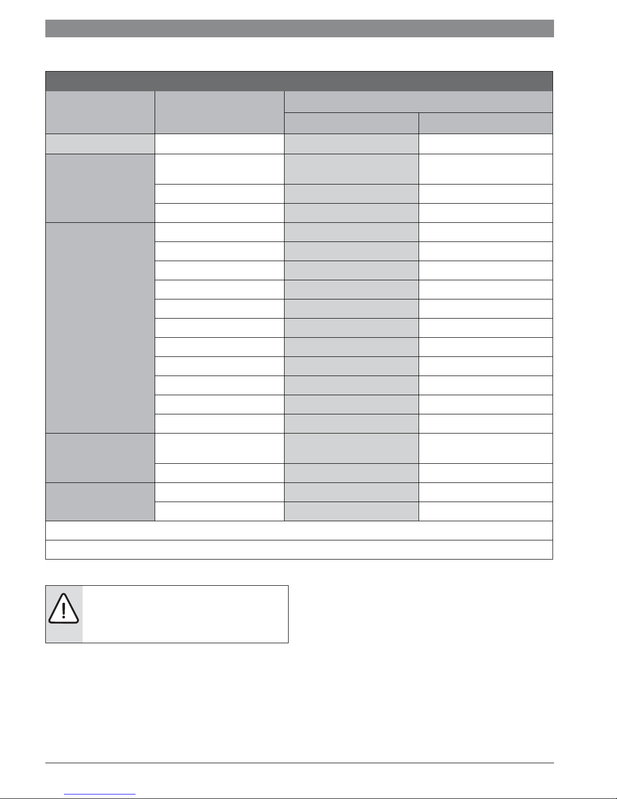
WATER QUALITY TABLE
Table 1: Water Quality
POTENTIAL
PROBLEM
SCALING
CORROSION
Water Characteristic Acceptable Value
Copper Cupro-Nickel
pH (Acidity/Alkalinity) 7-9 7-9
Hardness (CaCO3,
MgCO3)
Ryznar Stability Index
Langelier Saturation Index -0.5 - +0.5 -0.5 - +0.5
Hydrogen Sulfide (H2S) < 0.5 ppm * 10-50 ppm
Sulfates
Chlorine
Chlorides
Carbon Dioxide
Ammonia
Ammonia Chloride
Ammonia Nitrate
Ammonia Hydroxide
< 350 ppm < 350 ppm
6.0 - 7.5 6.0 - 7.5
< 125 ppm < 125 ppm
< 0.5 ppm < 0.5 ppm
< 20 ppm < 150 ppm
< 50 ppm < 50 ppm
< 2 ppm < 2 ppm
< 0.5 ppm < 0.5 ppm
< 0.5 ppm < 0.5 ppm
< 0.5 ppm < 0.5 ppm
Ammonia Sulfate
Dissolved Solids
Iron (Fe2+ Iron Bacteria
IRON FOULING
EROSION
* No "rotten egg" smell present at < 0.5 ppm H2S.
** Equivalent to 30 mesh strainer
Potential)
Iron Oxide
Suspended Solids < 10 ppm, < 600 µm size ** < 10 ppm, < 600 µm size **
Maximum Water Velocity
WATER QUALITY
NOTE: Failure to insure proper water quality
and flow rates can shorten the life of the
heat pump and potentially void the unit
warranty.
Maintaining proper water quality is important for
insuring a long and trouble free service life for an
SV series heat pump.
< 0.5 ppm < 0.5 ppm
< 1,000 ppm < 1,500 ppm
< 0.2 ppm < 0.2 ppm
< 1 ppm < 1 ppm
6 ft/sec 6 ft/sec
For closed loop and boiler/tower systems water
chemistry can be checked and easily maintained to
insure that corrosive elements, dissolved oxygen
and pH levels are kept in check. It is important to
insure that any additive, antifreeze or corrosion
inhibitor that is added to the water loop is
compliant with all applicable laws and regulations
and is compatible with copper, brass and bronze
alloys. Insure that all recommended safety
precautions are followed when handling or adding
chemicals to the water loop.
SV Heat Pump Series8 733 914 818 (2014?08) Subject to change without prior notice
Installation | 7Revised 08/14
For open loop systems, water quality is very
important. Table #1 shows acceptable ranges for a
variety of water quality factors. The three main
concerns in open loop installations are scaling,
corrosion and fouling.
In installations with hard water, scaling due to a
buildup of carbonates on the heat exchanger wall
can gradually degrade the heat pump performance
over time. Heat pumps that are affected by scaling
may exhibit low suction pressures in heating and
high head pressures in cooling with a gradual loss
of capacity and efficiency. Scaled heat exchangers
can be cleaned by a qualified technician but care
should be taken to avoid scaling in the first place.
To limit scaling, water flow rates should be kept at
3 gallons/minute per nominal cooling ton (a 10°F
temperature rise in cooling) and care should be
taken to avoid air in the water lines from suction
side leaks. Cupro-nickel coils are generally
recommended.
In installations with high hydrogen sulfide, chlorine
or ammonia, corrosion is a potential problem. In
these installations a cupro-nickel heat exchanger is
recommended along with maintaining proper flow
and keeping air out of the system. If water quality
is outside of the values in Table #1, then a closed
loop is recommended.
Fouling due to iron bacteria can also pose
problems in some open loop installations. Iron
bacteria fouling can quickly degrade system
performance and plug heat exchangers.
Air in the water system will greatly accelerate the
fouling or corrosion process.
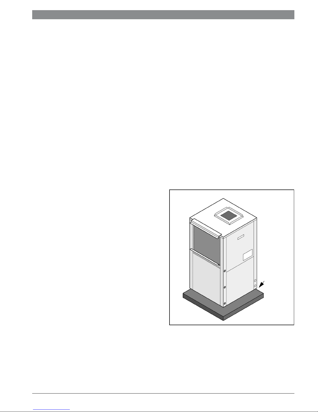
Mounting Vertical Units
SV Series vertical and counter flow units should be
mounted level on a vibration absorbing pad slightly
larger than the unit base in order to minimize
vibration transmission from the unit to the building
structure. See Figure #1. It is generally not
necessary to anchor the unit unless required by
local code.
All major service access for the SV Series vertical
and counter flow models is from the front side of
the unit. When installing the unit in a confined
space such as a closet, insure that the service
panel screws are accessible, that the filter can be
replaced without damage and that water and
electrical connections are accessible. For models
with a unit mounted disconnect switch, make sure
the switch can be easily seen and operated.
To reduce sound transmission, units should be
installed using flexible electrical conduit and hose
kits. Care should be taken to insure that no part of
the unit cabinet is touching part of the building
structure. For ducted return applications, a
flexible duct connection should be used. Refer to
Figure’s #14, #15 and #13.
INSTALLATION
The following are instructions to follow for
installation of all SV Series components.
Duct Flanges
SV heat pumps feature fold-out return and supply
air duct flanges. These fold-out flanges allow the
heat pumps to more easily fit through doorways
and other tight spaces, and also prevent damage in
shipping and handling.
It is recommended that all fold-out flanges be
folded-out once the heat pump is installed to
insure that return and supply air flow is not
obstructed. These flanges can be easily folded
using standard or duckbill pliers. Once folded out
these flanges can be used to support light duct
work loads.
Vibration
Mounting
Pad
Figure # 1 Mounting Vertical Units
Mounting Horizontal Units
While horizontal units may be installed on any level
surface strong enough to hold their weight, they
are typically suspended above a ceiling by
threaded rods. The rods are usually attached to the
unit corners by hanger bracket kits (P/N 930-008).
8 733 914 818 (2014/08)SV Heat Pump Series
8 | Hanging Bracket Kit SV Heat PumpSeries
Units larger than six tons include an integral
angle iron frame with mounting holes present.
(See unit horizontal detail drawing).
Horizontal units installed above the ceiling must
conform to all local codes. An auxiliary drain pan if
required by code, should be at least four inches
larger than the bottom of the heat pump.
Plumbing connected to the heat pump must not
come in direct contact with joists, trusses, walls,
etc. Some applications require an attic floor
installation of the horizontal unit. In this case the
unit should be set in a full size secondary drain pan
on top of a vibration absorbing mesh.
The secondary drain pan prevents possible
condensate overflow or water leakage damage to
the ceiling. The secondary drain pan is usually
placed on a plywood base isolated from the ceiling
joists by additional layers of vibration absorbing
mesh. In both cases, a 3/4" drain connected to this
secondary pan should be run to an eave at a
location that will be noticeable.
NOTE: If the unit is located in a crawl space,
the bottom of the unit must be at least 4"
above grade to prevent flooding of the
electrical parts due to heavy rains.
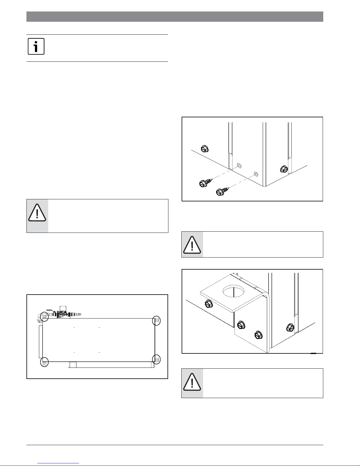
HANGING BRACKET KIT
Installation Instructions
All horizontal units come with Hanging Bracket kit
to facilitate suspended unit mounting using
threaded rod. Hanging Brackets are to be installed
as shown in figure # 2
(10) Bolts 1/4-28x1/2” Hex Bolt ( not used on this
model)
The following are needed and are to be field
provided:
Threaded rod (3/8” max dia)
Hex Nuts
Washers (1-3/4” min O.D.)
1. Remove and discard factory provided screws
from location where Hanging Brackets will be
installed shown in Figure#3
Figure # 3
2. Mount 5 brackets to unit corner post using the
bolts provided in the kit as shown on Figure # 4
WARNING: Do not re-use screws removed
from the unit on step 1 to mount the
hanging Brackets to the unit.
Figure # 2
This kit includes the following:
(5) Brackets.
(5) Rubber Vibrators Isolators.
(8) Screws # 10x1/2”
Figure # 4
WARNING: Follow all applicable codes
requirements when hanging this unit.
Selecting threaded rod material, etc.
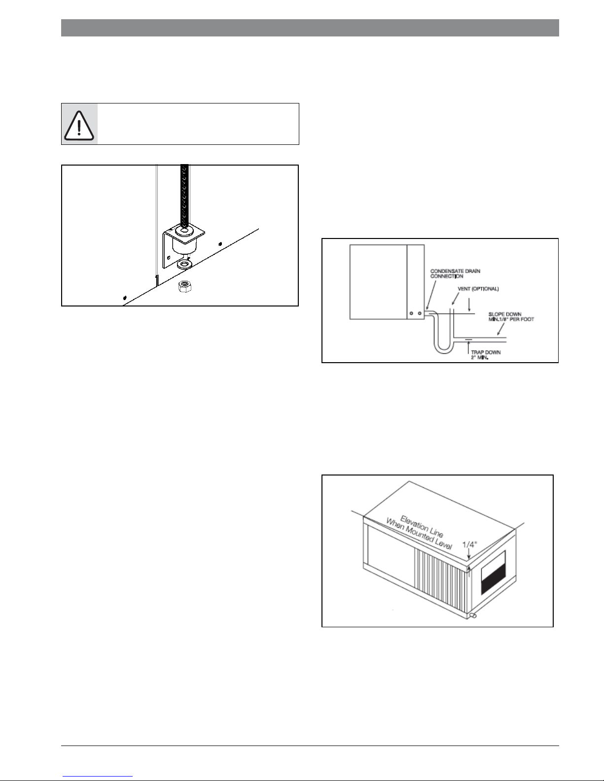
3. Install Rubber Grommet on the Bracket as
shown in Figure#5
SV Heat Pump Series8 733 914 818 (2014?08) Subject to change without prior notice
Converting Horizontal Supply Air Configuration | 9Revised 08/14
4. Hang the unit and assemble the field provided
Thread Rod, Nuts and washers on to the Brackets
as shown in Figure#5
CAUTION: Rods must be securely anchored
to the ceiling.
CONVERTING HORIZONTAL SUPPLY AIR
CONFIGURATION
The supply air location on SV Series Horizontal
units can be quickly field converted from end blow
to straight through or vice-versa. To convert the
supply air direction, follow the steps below:
1. If connected to power, shut off the unit and
disconnect switch or circuit breaker.
2. Unscrew and remove the blower access panel.
3. Disconnect the wires from the unit electrical
box to the blower motor. Note which speed
taps are wired for units with PSC or constant
torque motors.
4. Unscrew and carefully remove the blower
panel with the blower and motor attached. Be
careful not to damage the refrigerant coils or
any other internal unit components.
5. Remove the blower support brackets from the
bottom of the blower housing and relocate
them to the top of the blower housing.
6. Turn the blower panel 180° so that the blower
support brackets are now at the bottom of the
blower.
7. Insert the blower panel with the blower and
motor into the desired location. Be careful not
to damage the refrigerant coils or any other
internal unit components. Screw the panel into
place.
8. Replace the wires between the blower motor
and electrical box. Make sure to connect wires
to the proper speed taps.
9. Replace the blower access panel.
10. Reconnect power to the unit.
CONDENSATE CONNECTIONS
A drain line must be connected to the heat pump
and pitched away from the unit a minimum of 1/8”
per foot to allow the condensate to flow away from
the unit.
This connection must be in conformance with local
plumbing codes. A trap must be installed in the
condensate line to insure free condensate flow.
(Heat Pumps are not internally trapped).
A vertical air vent is sometimes required to avoid
air pockets.(See Figure #6).
Figure # 5 Condensate Drain
The depth of the trap depends on the amount of
positive or negative pressure on the drain pan. A
second trap must not be included.
The horizontal unit should be pitched
approximately 1/4” towards the drain in both
directions, to facilitate condensate removal. (See
Figure #6)
Figure # 6 Pitched Unit
DUCT SYSTEM
All SV Series models are provided with a return air
duct flange and supply air duct connections.
Refer to unit Dimensional Drawings for physical
dimensions of the collar and flange. (Pg#50)
8 733 914 818 (2014/08)SV Heat Pump Series
10 | Piping SV Heat PumpSeries
A flexible connector is recommended for supply
and return air duct connections on metal duct
systems. All metal ducting should be insulated
with a minimum of 1” (one inch) duct insulation to
avoid heat loss or gain and prevent condensate
from forming during the cooling operation.
Application of the unit to no insulated duct work is
not recommended as the unit’s performance will
be adversely affected.
NOTE: Do not connect discharge ducts
directly to the blower outlet.
The factory filter rack should be left in place
on a free return system.
If the unit will be installed in a new installation with
new duct work, the installation should be designed
using current ASHRAE procedures for duct sizing.
If the unit will be connected to an existing duct
system, a check should be made to assure that the
duct system has the capacity to handle the air
required for the unit application. If the duct system
is too small, larger duct work must be installed. Be
certain to check for existing leaks and repair.
The duct system and all diffusers should be sized
to handle the designed air flow quietly. To
maximize sound attenuation of the unit blower, the
supply and return air plenums should be insulated.
There should be no direct straight air path through
the air grill into the heat pump. The return air inlet
to the heat pump must have at least one 90° turn
away from the space return air grill. If air noise or
excessive air flow are a problem, the blower speed
can be changed to a lower speed to reduce air
flow.
In conditions anticipating moderate scale
formation or in brackish water a cupro-nickel heat
exchanger is recommended. Both the supply and
discharge water lines will sweat if subjected to low
water temperature. These lines should be
insulated to prevent damage from condensation.
All manual flow valves used in the system must be
ball valves. Globe and gate valves must not be used
due to high pressure drop and poor throttling
characteristics. Always check carefully for water
leaks and repair appropriately. Units are equipped
with female pipe thread fittings. Consult the
specification sheets for sizes.
Teflon tape sealer should be used when
connecting water piping connections to the units
to insure against leaks and possible heat
exchanger fouling. Do not overtighten the
connections. Flexible hoses should be used
between the unit and the rigid system to avoid
possible vibration. Ball valves should be installed
in the supply and return lines for unit isolation and
unit water flow balancing.
Pressure/temperature ports are recommended in
both the supply and return lines for system flow
balancing. The water flow can be accurately set by
measuring the water-to- refrigerant heat
exchangers water side pressure drop. See the unit
specification sheets for the water flow and
pressure drop information.
NOTE: Water piping exposed to extreme,
low ambient temperatures is subject to
freezing
PIPING
Supply and return piping must be as large as the
unit connections on the heat pump (larger on long
runs). Never use flexible hoses of a smaller inside
diameter than that of the water connections on the
unit. SV Units are supplied with either a copper or
optional cupro-nickel condenser. Copper is
adequate for ground water that is not high in
mineral content. Refer to Table #1.
Should your well driller express concern
regarding the quality of the well water available
or should any known hazards exist in your area,
we recommend proper testing to assure the well
water quality is suitable for use with water
source equipment. (Refer to Table #1)
NOTE: Never exceed the recommended
water flow rates. Serious damage or erosion
of the water to refrigerant heat exchanger
could occur.
SV Heat Pump Series8 733 914 818 (2014?08) Subject to change without prior notice
Electrical - High Voltage | 11Revised 08/14
ELECTRICAL - HIGH VOLTAGE
All field installed wiring must comply with the
National Electric Code as well as all applicable
local codes. Refer to the unit electrical data on the
unit name plate for wire and branch circuit
protection sizing. Supply power voltage and
phasing should match the required voltage and
phasing shown on the unit name plate. Operating
the unit below the minimum voltage, above the
maximum voltage or with incorrect phasing can
result in poor system performance or damage to
the heat pump. All field wiring should be installed
by qualified and trained personnel. Refer to the
unit wiring diagram for field connection
requirements.
NOTE: All power connections must be
properly torque to avoid the risk of
overheating.
Power wiring to the heat pump should be enclosed
in flexible conduit to minimize the transmission of
vibration from the unit cabinet to the building.
For heat pumps with unit mounted disconnect
switches, field power should be connected to the
marked terminals on the disconnect switch. For
heat pumps without unit mounted disconnect
switches (except for 460 volt units noted below
and units with dual power supply), power is
connected to the line (L) side of the compressor
contactor and the ground lug in the unit electrical
box.
Models with Dual Power Supplies
For models with dual power supplies, one power
supply feeds the compressor and a second power
supply feeds the unit fan motor and control circuit.
The compressor power supply should be
connected to the line (L) side of the compressor
contactor. The fan motor and control circuit
power supply should be connected to a provided
terminal block. Care should be taken to insure that
each power supply meets the voltage, amperage
and phase requirements of its load. Refer to the
unit nameplates for requirements.
460 V Models with Constant Air Flow
Motors (SV015-SV070)
460 volt SV heat pumps with the constant airflow
motor option require a properly sized neutral wire
with the power supply wiring in addition to the
three high voltage wires and the ground wire.
These units employ a 265 V motor that requires
power from one phase of the 460 V supply and the
neutral wire.
WARNING: The power supply ground wire
should never be used as a neutral wire.
For 460 V models with constant air flow motors
and a unit mounted disconnect switch, the power
wires and neutral wire should be connected to the
appropriate terminals on the disconnect switch
and its enclosure. For units without a disconnect
switch, power and neutral wires should be
connected to a provided 4 pole terminal block in
the unit electrical box
Transformer Settings for 208/230 V Units
As factory built, all 208/230 V units are wired for
230 V operation. For job sites with a 208 V power
supply, the primary leads on the unit transformer
will need to be changed from 240 V to 208 V. Refer
to the unit wiring diagram for details.
ELECTRICAL - LOW VOLTAGE
For heat pumps with PSC or constant torque fan
motors, all thermostat wiring is connected to a
terminal block located in the unit electrical box.
For heat pumps with a constant air flow fan motor,
thermostat wiring is connected to a removable
terminal strip located on the ECM motor control
board located in the electrical box. Refer to the
unit wiring diagram for connection details.
WARNING: Never route control wiring
through the same conduit as power supply
wiring.
Unless provided with DDC controls, the SV heat
pump can be controlled by most commonly
available single stage heat pump thermostats.
Note that the reversing valve on the SV series is
energized when the unit is in the cooling mode.
Thermostats should be located on an interior wall
away from supply ducts. Avoid locations subject to
direct sunlight or drafts, or external walls.
Thermostat wiring should be 18 AWG. Refer to the
installation instructions for the thermostat for
further details.
Exceptionally long runs of thermostat wire
should be avoided to prevent voltage drops in
the control circuit.
SV heat pumps are supplied with a 75 VA control
transformer as standard. The VA capacity of the
transformer should be considered when
connecting low voltage accessories to the heat
pump such as thermostats or solenoid valves.
8 733 914 818 (2014/08)SV Heat Pump Series
12 | Unit Controls - UPM SV Heat PumpSeries
Table #2 shows the VA draw of factory mounted
components in the SV heat pump. The total VA
draw of the heat pump internal components plus
any attached accessories must be lower than the
VA capacity of the unit control transformer.
NOTE: Exceeding the transformer capacity
can result in low control voltage, erratic unit
operation or damage to the heat pump.
Table 2: Low Voltage VA Draw
Standard
Hot Gas Reheat
Construction
Component
Blower Relay
(PSC motors only)
Reversing Valve
Solenoid
Compressor
Contactor
VA
6-7
8-9
6-8
Component
Total from
‘Standard’
Additional
Control
Relays
Hot Gas
Reheat
Solenoid
VA
22-26
12-14
8-9
10
8
9
7
1
546
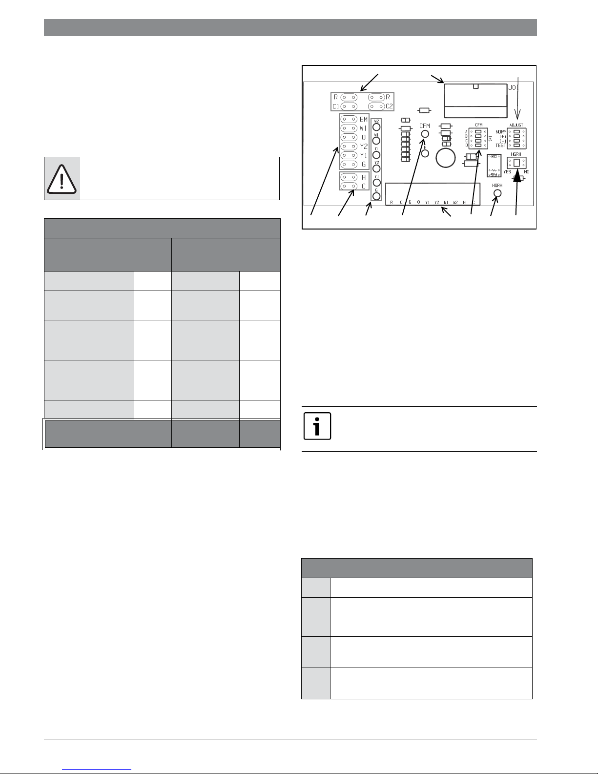
Figure # 7
[1] Motor harness plug
[2] Blower CFM adjustment
[3] Motor settings
[4] Dehumidification indication
[5] Thermostat contact inputs
[6] CFM count indicator
[7] Thermostat input status indication
[8] Reheat digital outputs
[9] Thermostat outputs
[10] 24 VAC
[11] Dehumidification method selector
3
11
UPM board
Total VA draw
2
22-26
Total VA
draw
42-49
UNIT CONTROLS - UPM
ECM Interface Board
Thermostat wiring is connected to the 10 pin
screw type terminal block on the lower center
portion of the ECM Interface Board (Refer to
Figure #7, item [5]). In addition to providing a
connecting point for thermostat wiring, the
interface board also translates thermostat inputs
into control commands for the Electronic
Commutated Motor (ECM) DC fan motor and
displays an LED indication of operating status. The
thermostat connections and their functions are as
Follows.
CFM LED indication is an approximation. Utilize
conventional Test and Balance equipment for
accurate airflow measurement.
• CFM Count Indicator (Figure #7, Item [5])
blinks to indicate approximate airflow in CFM
and may flicker when unit is off. Each blink of
the LED represents approximately 100 CFM of
air delivery, for example, if the LED blinks 12
times, pauses, blinks 12 times, etc. the blower
is delivering approximately 1200 CFM.
Thermostat Options
Y1 First Stage Compressor Operation
G Fan
O Reversing Valve (energized in cooling)
W1 Auxiliary Electric Heat (runs in
conjunction with compressor)
NC Transformer 24 VAC Common (extra
connection)
SV Heat Pump Series8 733 914 818 (2014?08) Subject to change without prior notice
Unit Controls - UPM | 13Revised 08/14
Thermostat Options
Y1 First Stage Compressor Operation
C1 Transformer 24 VAC Common (primary
connection)
R Transformer 24 VAC Hot
H Dehumidification Mode
Airflow Selector
The airflow selector (Figure #7, items [2] & [3])
allows airflow adjustment to meet application
requirements and to ease troubleshooting.
Only one switch can be enabled at a time. Refer
to Figure #9 for each airflow setting.
NOTE: CFM Selector (FIg #7, Item [2]) must
remain with only “A” being enabled.
ADJUST Selector can be adjusted to NOM, (+), (-),
or TEST. NOM, (+) and (-) can be adjusted as
needed by application. TEST is used for
troubleshooting to override unit airflow to 100%
NOTE: Always disconnect power before
changing jumper positions on the interface
board and reset the unit afterward.
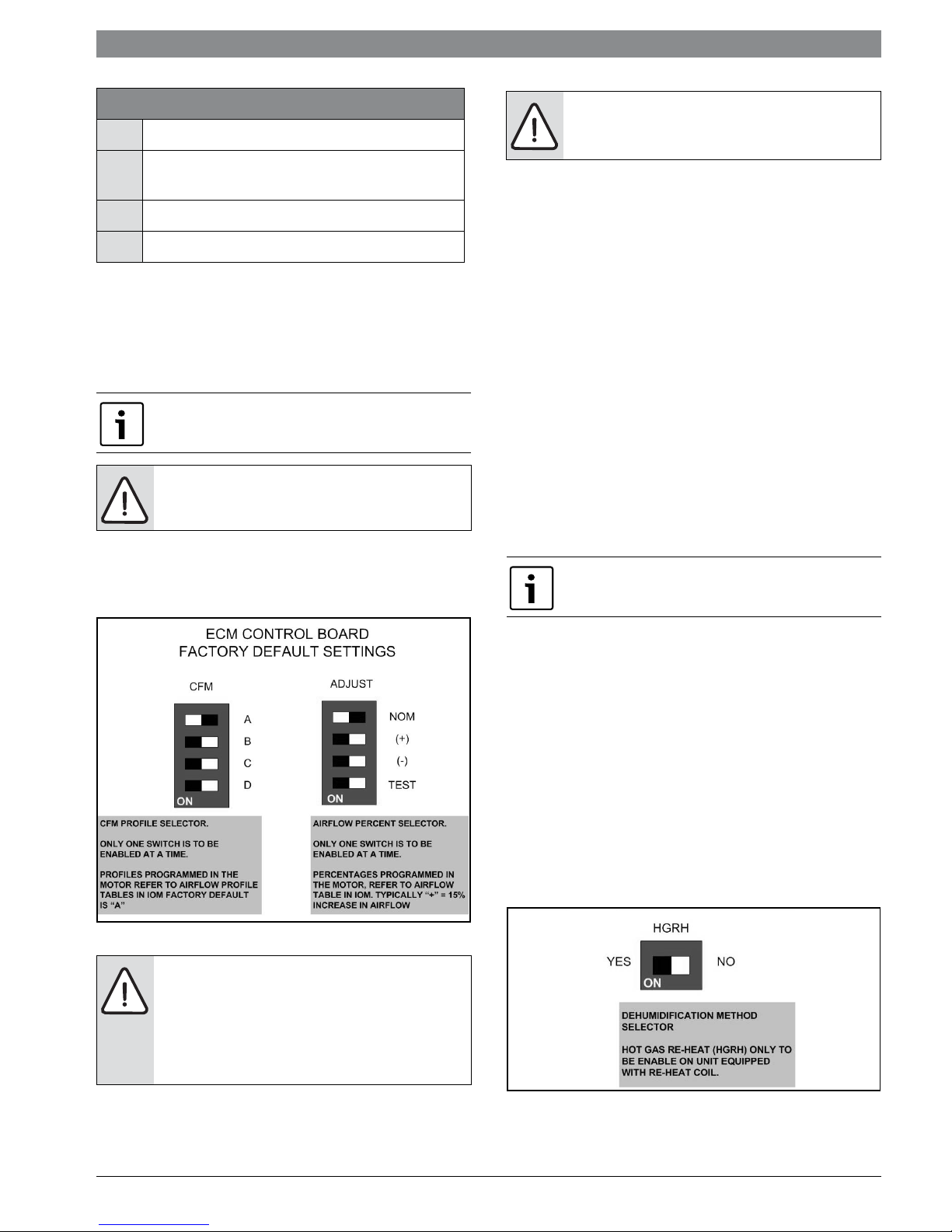
Dehumidification Method Selector
Dehumidification method selector (Figure #7, item
[11]) is used to select between the following two
methods:
1. Units equipped with optional Hot Gas Reheat,
on dehumidification call (the “H” terminal on
the thermostat is energized) the reheat
outputs will energize the hot gas reheat valve
in the circuit and the heat pump will start in
dehumidification mode. Dehumidification
selector (Figure #7, item [11]) should be
selected to ‘YES’.
2. Units without optional Hot Gas Reheat, on
dehumidification call, the heat pump fan will
operate at a lower speed to increase
dehumidification while cooling.
Dehumidification selector ((Figure #7, item
[11]) should be selected to ‘NO’.
In this mode, the heat pump will only dehumidify
the space when it is running in cooling mode.
Figure # 8
NOTE: Do not set the ADJ DIP switch to the
(-) setting when electric heaters are
installed. Doing so may cause the heaters to
cycle on their thermal overload switches,
potentially shortening the life of the
switches.
3. To the left of the red and green status LED’s is
a row of 1/4” male quick connects. These are
used to pass thermostat inputs on to the rest
of the control circuit. Remember to always turn
off unit power at the circuit breaker before
attaching or disconnecting any wiring from
these connections to avoid accidental short
circuits that can damage unit control
components.
Dehumidification indicator LED (Figure #7, item
[4]) will energize when dehumidification call is
present. Refer to Figure #9.
The other DIP switch bank is used to select the
proper program in the ECM motor for the unit.
Figure # 9
8 733 914 818 (2014/08)SV Heat Pump Series

14 | Unit Controls - UPM SV Heat PumpSeries
Sequence of Operation
START
YES
Y1 = ON
NO
RESET ON
Y
NO
RESET ON R
R = 24VAC
YES
POWER/ SWITCHES/SENSOR
STATUS CHECK
V > 18VAC
NO
YES
HPC =
CLOSED
NO
YES
LPC
=CLOSED
NO
YES
FRZ >TEMP
LIMIT
NO
START
TIMER
START
TIMER
YES
CLEAR FAULTS
TIME > 120
NO
TIME > 30
BLINK CODE ON STATUS LED
SOFT LOCKOUT
RECORD ALARM
START COUNTER (IF APPLICABLE)
LOCKOUT CAN BE SET
TO 4 VIA DIP SWITCH
BLINK CODE
SEC
SEC
YES
ON STATUS LED
YES
NO
COUNTER
NEEDED?
YES
COUNT = 2
OR
COUNT = 4
NO
YES
NO
HARD
LOCKOUT?
YES
BLINK CODE ON STATUS LED
DISPLAY OUTPUT = PULSE
ALR OUTPUT = ON/PULSE
NO
YES
CON > 0
YES
INITIAL
POWER UP
YES
NO
NO
NO
START
ANTI SHORT CYCLE
START
RANDOM START UP
NO
T > ASC OR
RS SEC
CC OUTPUT = OFF
YES
CC
CC OUTPUT = ON
LEGEND:
HPC - HIGH PRESSURE CUTOUT
LPC - LOW PRESSURE CUTOUT
FRZ - FREEZE PROTECTION CONDITION
CON - CONDENSATE OVERFLOW CONDITION
CC - COMPRESSOR COIL
ASC - ANTI SHORT CYCLE
RS - RANDDOM START
SV Heat Pump Series8 733 914 818 (2014?08) Subject to change without prior notice
Unit Controls - UPM | 15Revised 08/14
General
SV series heat pumps are designed to be
controlled by a standard 1 heat / 1 cool heat pump
thermostat. The heat pump control circuit
operates on 24 VAC control voltage regardless of
the unit supply voltage. If direct digital control is
required then the heat pump needs to be supplied
with a DDC control option.
Fan operation is controlled by the “G” terminal on
the heat pump thermostat terminal block. When
“G” is energized the unit fan motor will start
operating. For heat pumps with PSC motors, the
fan will immediately ramp up to 100% air flow. For
heat pumps with constant torque ECM motors, the
fan will ramp up to 100% air flow over a 30 second
period. For heat pumps with constant air flow ECM
motors the fan will ramp up to 70% air flow over a
30 second period if there is no call for compressor
operation (“Y”). If there is a call for compressor
operation along with a call for fan operation, then
the fan will ramp to 100% air flow.
Compressor operation is controlled by the “Y”
terminal on the heat pump thermostat terminal
block. When “Y” is energized, a signal to start the
compressor is sent to the Unit Protection Module
(UPM). The UPM checks a number of safety
features before then starting the compressor. If
any of the safety features connected to the UPM is
in a fault condition, the UPM will not start the
compressor and will flash a fault code on the red
status LED indicating the nature of the fault.
Additionally the UPM will delay compressor
operation randomly on initial start up (random
start delay) and will prevent the compressor from
restarting with less than 5 minutes of off time (anti
short cycle delay). Once all faults are cleared and
the time delays are satisfied, the UPM will energize
the compressor. The compressor will operate as
long as the thermostat calls for “Y” and there are
no faults. Refer to the troubleshooting chart for
fault diagnostics.
Cooling and Heating Modes
SV series heat pumps operate in cooling with the
reversing valve energized. When the “O” terminal is
energized, the heat pump will be in the cooling
mode, however, will not be actively cooling until
the “Y” and “G” terminals are also energized. If the
“Y” and “G” terminals are energized without the
“O” terminal, then the heat pump will operate in
the heating mode.
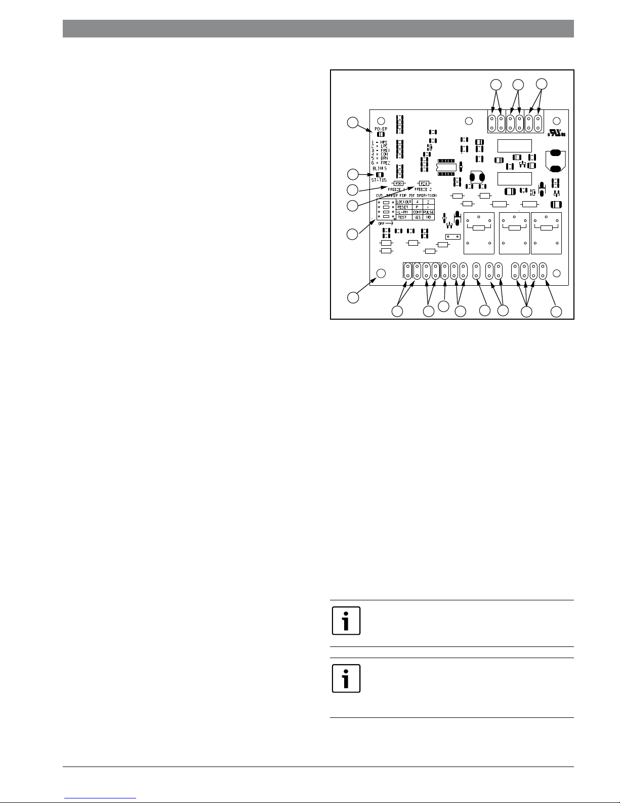
UPM Safety Features
11
1213
1
2
3
4
5
17
6
[1] Board Power Indicator
[2] UPM Status LED Indicator
[3] Water Coil Freeze Protection Temperature
Selection
[4] Air Coil Freeze Protection Temperature
Selection
[5] UPM Board Settings
[6] Water Coil Freeze Connection
[7] Air Coil Freeze Connection
[8] LED Unit Display Connection
[9] 24VAC Power Input
[10] Compressor Contact Output
[11] High Pressure Switch Connection
[12] Call for Compressor Y1
[13] Low Pressure Switch Connection
[14] 24VAC Power Common
[15] Condensate Overflow Sensor
[16] Dry Contact
[17] UPM Ground Standoff
If the unit is being connected to a thermostat
with a malfunction light, this connection is made
at the unit malfunction output or relay.
If the thermostat is provided with a malfunction
light powered off of the common (C) side of the
transformer, a jumper between “R” and “COM”
terminal of “ALR” contacts must be made.
15
14
7
Figure # 10
8
16
9
10
8 733 914 818 (2014/08)SV Heat Pump Series
16 | Unit Controls - UPM SV Heat PumpSeries
If the thermostat is provided with a malfunction
light powered off of the hot (R) side of the
transformer, then the thermostat malfunction
light connection should be connected directly to
the (ALR) contact on the unit’s UPM board.
Each unit is factory provided with a Unit Protection
Module (UPM) that controls the compressor
operation and monitors the safety controls that
protect the unit.
Safety controls include the following:
• High pressure switch located in the refrigerant
discharge line and wired across the HPC
terminals on the UPM
• Low pressure switch located in the unit
refrigerant suction line and wired across
terminals LPC1 and LPC2 on the UPM.
UPM Board Dry Contacts are Normally Open
(NO)
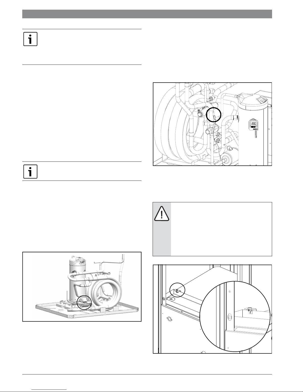
• Water side freeze protection sensor, mounted
close to condensing water coil, monitors
refrigerant temperature between condensing
water coil and expansion valve or capillary
tube. If temperature drops below or remains at
freeze limit trip for 30 seconds, the controller
will shut down the compressor and enter into
a soft lockout condition. The default freeze
limit trip is 26°F, however this can be changed
to 15°F by cutting the R30 or Freeze1 resistor
located on top of DIP switch SW1.
• Evaporator freeze protection sensor, mounted
after the thermal expansion device and the
evaporator, monitors refrigerant temperature
between the evaporator coil and thermal
expansion valve. If temperature drops below or
remains at freeze limit trip for 30 seconds, the
controller will shut down the compressor and
enter into a soft lockout condition. The default
freeze limit trip is 26°F. (Figures #11 and #12)
Figure # 12
• The condensate overflow protection sensor is
located in the drain pan of the unit and
connected to the ‘COND’ terminal on the UPM
board. (Figure #13)
NOTE: If unit is employing a fresh water
system (no anti-freeze protection), it is
extremely important to have the Freeze1
R30 resistor set to 26°F in order to shut
down the unit at the appropriate leaving
water temperature and protect your heat
pump from freezing if a freeze sensor is
included.
Figure # 11
Figure # 13
SV Heat Pump Series8 733 914 818 (2014?08) Subject to change without prior notice
Unit Controls - UPM | 17Revised 08/14
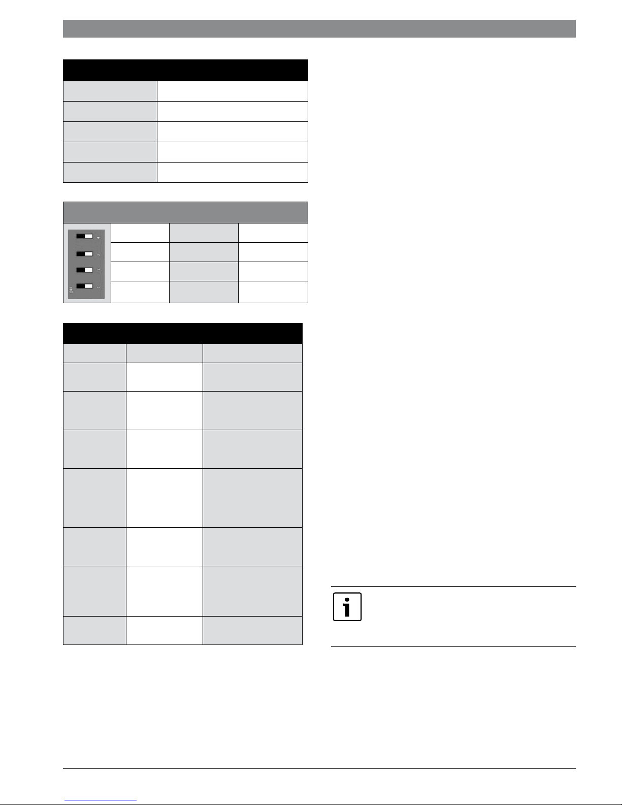
UPM Board Factory Default Settings
TEMP
LOCKOUT
RESET
ALARM
TEST
26°F
2
Y
PULSE
NO
UPM DIP SWITCH DEFAULT POSITION
lockout 42
reset
alarm
test
Table 3: UPM Fault Blink Codes
LED Blinks Fault Fault Criteria
None None
1 High Pressure
2 Low Pressure
Water Coil
Freeze
3
4
5
6 Brown Out
Condition
Condensate
Overflow
Air Coil Freeze
Condition
RY
Cont pulse
yes no
All fault conditions
nominal
Refrigerant discharge
pressure has
exceeded 600 PSIG
Refrigerant suction
pressure has fallen
below 40 PSIG
Refrigerant
temperature to the
water coil has fallen
below 30°F for 30
seconds
Condensate levels in
the unit drain pan are
too high
Refrigerant
temperature to the air
coil has fallen below
30°F for 30 seconds
Control voltage has
fallen below 18 VAC
• RANDOM START: Each controller has an unique
random start delay ranging from 270 to 300 seconds
on initial power up to reduce the chance of multiple
unit simultaneously starting at the same time after
power up or after a power interruption, thus
avoiding creating large electrical spike.
• LOW PRESSURE BYPASS TIMER: If the
compressor is running and the low pressure switch
opens, the controller will keep the compressor ON
for 120 seconds. After 120 seconds if the low
pressure switch remains open, the controllers will
shut down the compressor and enter a soft lockout.
The compressor will not be energized until the low
pressure switch closes and the anti-short cycle time
delay expires. If the low pressure switch opens 2-4
times in 1 hour, the unit will enter a hard lockout. In
order to exit hard lockout power to the unit would
need to be reset.
• BROWNOUT/SURGE/POWER
INTERRUPTION PROTECTION: The brownout
protection in the UPM board will shut does the
compressor if the incoming power falls below 18
VAC. The compressor will remain OFF until the
voltage is above 18 VAC and ANTI-SHORT CYCLE
TIMER (300 seconds) times out. The unit will not go
into a hard lockout.
• MALFUNCTION OUTPUT: Alarm output is
Normally Open (NO) dry contact.
If pulse is
selected the alarm output will be pulsed. The
fault output will depend on the dip switch
setting for "ALARM". If it is set to "CONST", a
constant signal will be produced to indicate a
fault has occurred and the unit requires
inspection to determine the type of fault. If it is
set to "PULSE", a pulse signal is produced and
a fault code is detected by a remote device
indicating the fault. See L.E.D Fault Indication
below for blink code explanation. The remote
device must have a malfunction detection
capability when the UPM board is set to
"PULSE".
If 24 VAC output is needed R must be wired to
ALR-COM terminal; 24 VAC will be available o
the ALR-OUT terminal when the unit is in the
alarm condition.
The UPM Board includes the following features:
• ANTI-SHORT CYCLE TIMER: 5 minute delay on
break timer to prevent compressor short cycling.
• DISPLAY OUTPUT: The Display output is a pulse
output connected to the Unit Diagnostic Display
(UDD) and it pulses 24VAC when the unit is in an
lockout alarm condition.
8 733 914 818 (2014/08)SV Heat Pump Series
 Loading...