

Bosch SST150-40, SST250-65, SST300-80, SST450-119 Installation And Operating Manual
Indirect Fired Water Heaters
Installation and Operating Manual
Models: SST150-40
SST250-65
SST300-80
SST450-119
CAUTION
The heat transfer medium must be water or other nontoxic uid
having a toxicity rating or class of 1, as listed in Clinical
Toxicology of Commercial Products, 5th edition
The pressure of the heat transfer medium must be limited to a
maximum of 30 PSIG by an approved safety or relief valve.
®
C
US
WARNING
This manual must only be used by a trained heating installer /
service technician. Read all instructions before installing.
Perform steps in the order given. Failure to comply could result
in severe personal injury, death, or substantial property
damage.

Installation & Operating Manual
2 |
Indirect Fired Water Heaters Installation and Operating Manual

Table of Contents
1 General Information 6
Installation & Operating Manual
2 Pre-installation 7
3 Boiler Side Piping 8
4 Domestic Side (Tank) Piping 13
5 Wiring 17
6 Start-up and Check-out 18
7 Maintenance 19
8 Performance Data 21
Limited Lifetime Warranty 25
Indirect Fired Water Heaters Installation and Operating Manual
| 3
Installation & Operating Manual
Hazard Denitions
The following dened terms are used throughout this
manual to bring attention to the presence of hazards of
various risk levels or to important information concerning
the life of the product.
DANGER
DANGER indicates an imminently hazardous situation
which, if not avoided, will result in death or serious
injury.
WARNING
WARNING indicates a potentially hazardous situation
which, if not avoided, could result in death or serious
injury.
CAUTION
CAUTION indicates a potentially hazardous situtation
which, if not avoided, may result in minor or
moderate injury.
CAUTION
CAUTION used without the safety alert symbol
indicates a potentially hazardous situation which, if
not avoided, may result in property damage.
NOTICE
NOTICE indicates special instructions on installation,
operation, or maintenance that are important but not
related to personal injury or property damage.
4 |
Indirect Fired Water Heaters Installation and Operating Manual
Installation & Operating Manual
Please Read Before Proceeding
WARNING
Installer – Read all instructions before installing.
Perform steps in the order given. Have this indirect
water heater serviced/inspected by a qualified
service technician, at least annually. Failure to comply
with the above could result in severe personal injury,
death or substantial property damage.
NOTICE
When calling or writing about the appliance
– Please have the indirect water heater model and
serial number from the indirect water heater rating
plate.
– Consider piping and installation when determining
appliance location.
– Any claims for damage or shortage in shipment
must be filed immediately against the
transportation company by the consignee.
– Factory warranty does not apply to appliances
improperly installed or improperly operated.
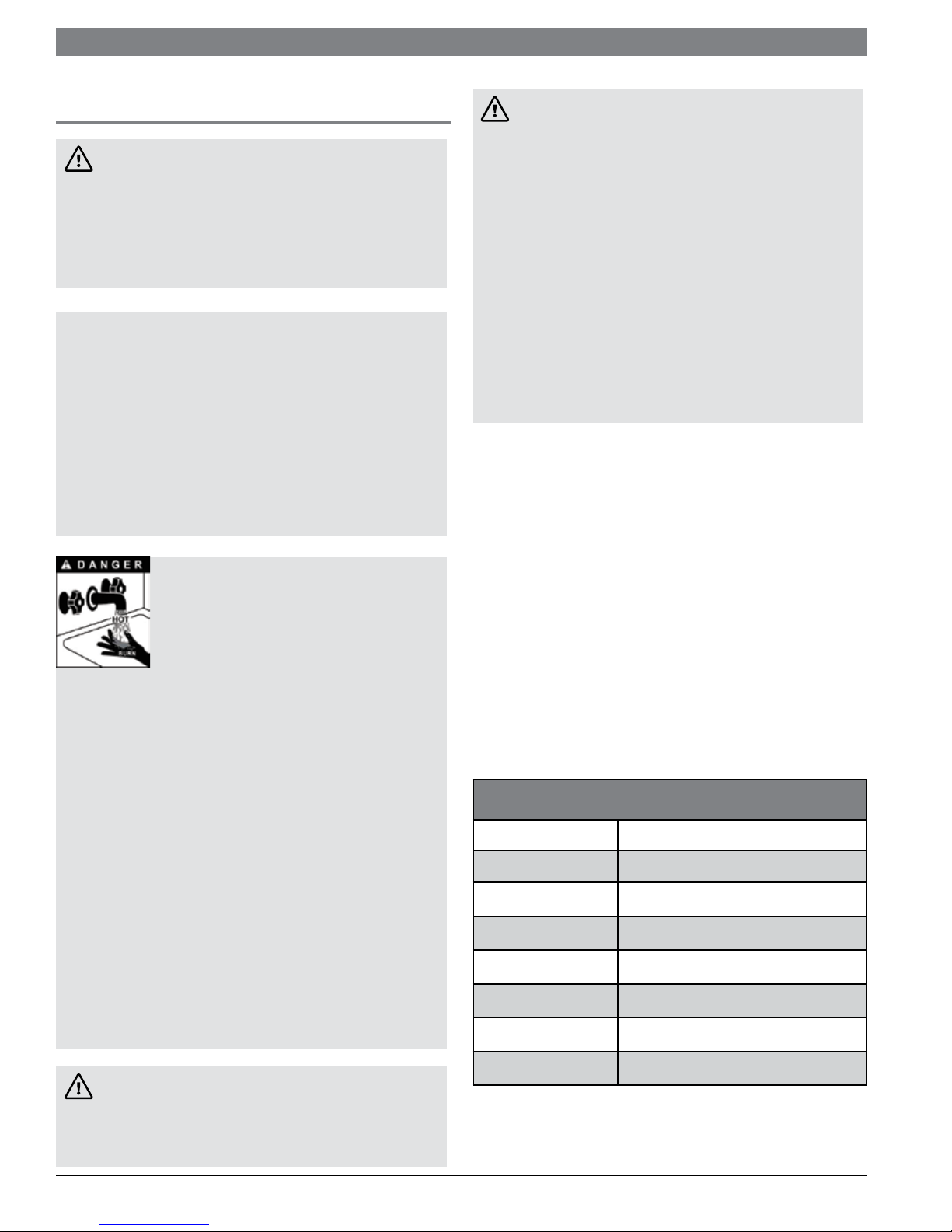
HOT WATER CAN SCALD!
• Water heated to temperatures for
clothes washing, dish washing, and other
sanitizing needs can scald and cause
permanent injury.
• Children, elderly, and infirm or physically handicapped
persons are more likely to be permanently injured by
hot water. Never leave them unattended in a bathtub or
shower. Never allow small children to use a hot water
tap or draw their own bath.
• If anyone using hot water in the building fits the above
description, or if state laws or local codes require
certain water temperatures at hot water taps, you must
take special precautions:
• Use lowest possible temperature setting.
• Install some type of tempering device, such as an
automatic mixing valve, at hot water tap or water
heater. Automatic mixing valve must be selected and
installed according to valve manufacturer’s
recommendations and instructions.
• Water passing out of drain valves may be extremely
hot. To avoid injury:
• Make sure all connections are tight.
• Direct water flow away from any person
• Protection Must Be Taken Against Excessive
Temperature and Pressure! Installation of a
Temperature & Pressure (T&P) relief valve is required.
WARNING
If the information in this manual is not followed
exactly, a fire or explosion may result causing
property damage, personal injury or loss of life.
This appliance MUST NOT be installed in any location
where gasoline or flammable vapors are likely to be
present.
WHAT TO DO IF YOU SMELL GAS
• Do not try to light any appliance.
• Do not touch any electric switch; do not use any
phone in your building.
• Immediately call your gas supplier from a neighbor’s
phone. Follow the gas supplier’s instructions.
• If you cannot reach your gas supplier, call the fire
department.
• Installation and service must be performed by a
qualified installer, service agency, or the gas
supplier.
When Servicing the Indirect Water Heater -
To avoid severe burns, allow the appliance to cool
before performing maintenance.
Indirect water heater operation –
Should overheating occur or gas supply fail to shut off, do
not turn off or disconnect electrical supply to circulator.
Instead, shut off the gas supply at a location external to
the appliance.
Do not use this appliance if any part has been under
water. The possible damage to a ooded appliance can be
extensive and present numerous safety hazards. Any
appliance that has been under water must be replaced.
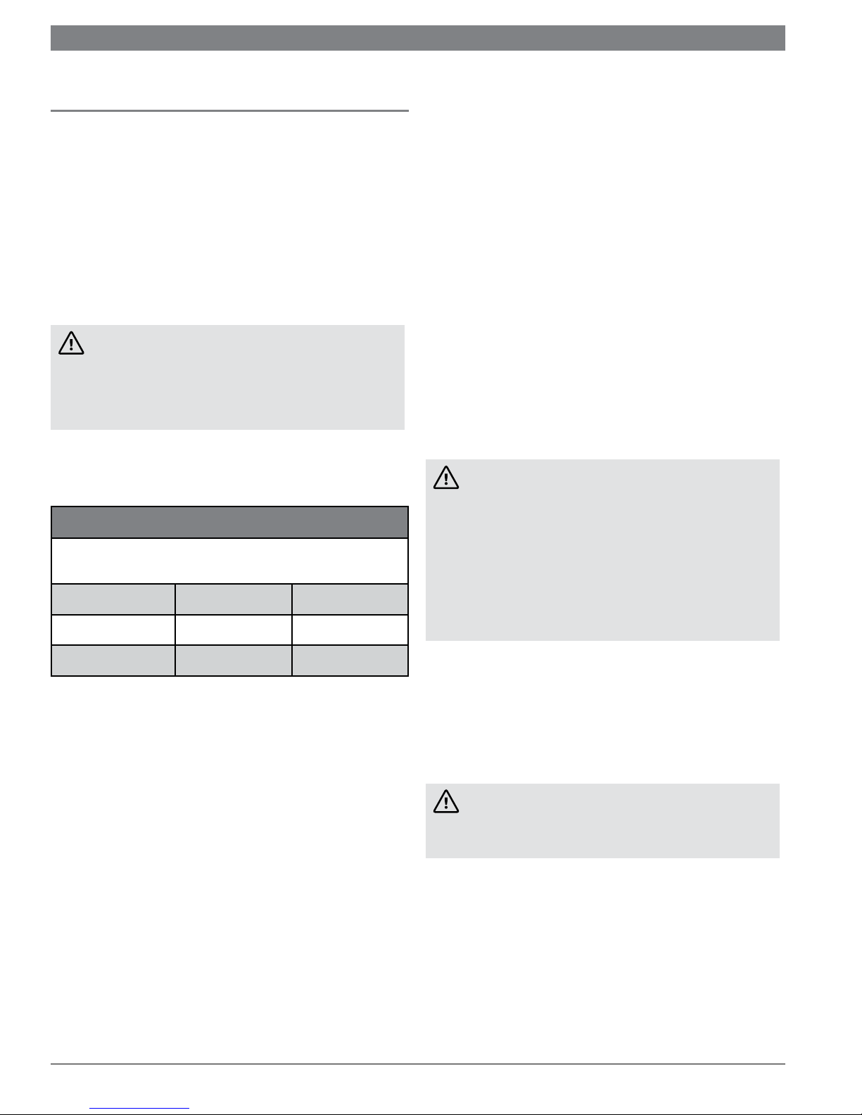
The following chart details the relationship of water
temperature and time with regard to scald injury and may
be used as a guide in determining the safest water
temperature for your applications.
APPROXIMATE TIME / TEMPERATURE
RELATIONSHIPS IN SCALDS
120° F More than 5 minutes
125° F 1 ½ to 2 minutes
130° F About 30 seconds
135° F About 10 seconds
140° F Less than 5 seconds
145° F Less than 3 seconds
150° F About 1 ½ seconds
WARNING
Failure to adhere to the guidelines on this page can
result in severe personal injury, death, or substantial
property damage.
Indirect Fired Water Heaters Installation and Operating Manual
155° F About 1 second
| 5
Installation & Operating Manual
1 General Information
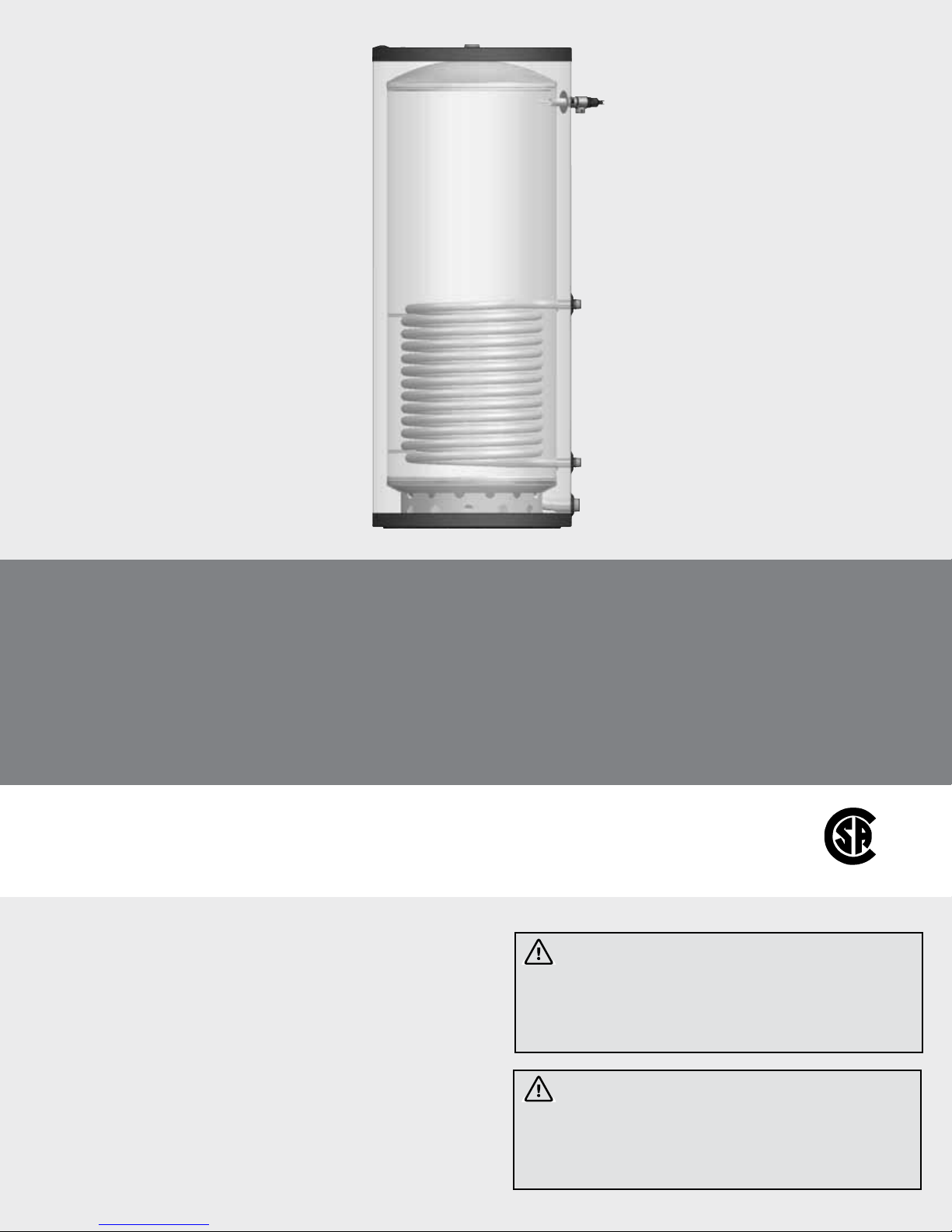
The SST series indirect water heater (FIG. 1-1) is designed
to generate domestic hot water in conjunction with a hot
water boiler using forced boiler water circulation. This
indirect water heater consists of a 316L Stainless Steel
tank in which a smooth 304L stainless steel coil is located
(Table 1A). Boiler water is pumped through the coil and
heats the water in the tank. This tank is not intended for
use in pool heating applications or for heating any uid
other than water. It is also not intended for use in gravity
hot water heating systems.
Operating Restrictions:
• Maximum domestic hot water temperature is 194°F.
• Maximum boiler water temperature is 210°F.
• Maximum working pressure for the vessel tank is 150
psig.
Component Materials Table 1A
Component Material
Tank 316L Steel Stainless Steel
Coil 304L Stainless Steel
Insulation Polyurethane
Jacket Polypropylene/ABS
Single-Wall Heat Exchanger
National Standard Plumbing Code
Single-wall heat exchangers in water heaters comply with
the National Standard Plumbing Code provided that:
• boiler water (including additives) is practically non-toxic,
having a toxicity rating or class of 1, as listed in Clinical
Toxicology of Commercial Products, and
• boiler water pressure is limited to a maximum of 30 psig
by approved relief valve.
Uniform Plumbing Code
Single-wall heat exchangers are permitted if they satisfy all
of the following requirements:
1. The heat transfer medium is potable water or contains
only substances which are recognized as safe by the
U.S. Food and Drug Administration.
2. The pressure of the heat transfer medium is maintained
less than the normal minimum operating pressure of the
potable water system.
3. The equipment is permanently labeled to indicate that
only additives recognized as safe by the FDA shall be
used in the heat transfer medium.
Other heat exchanger designs may be permitted where
approved by local code.
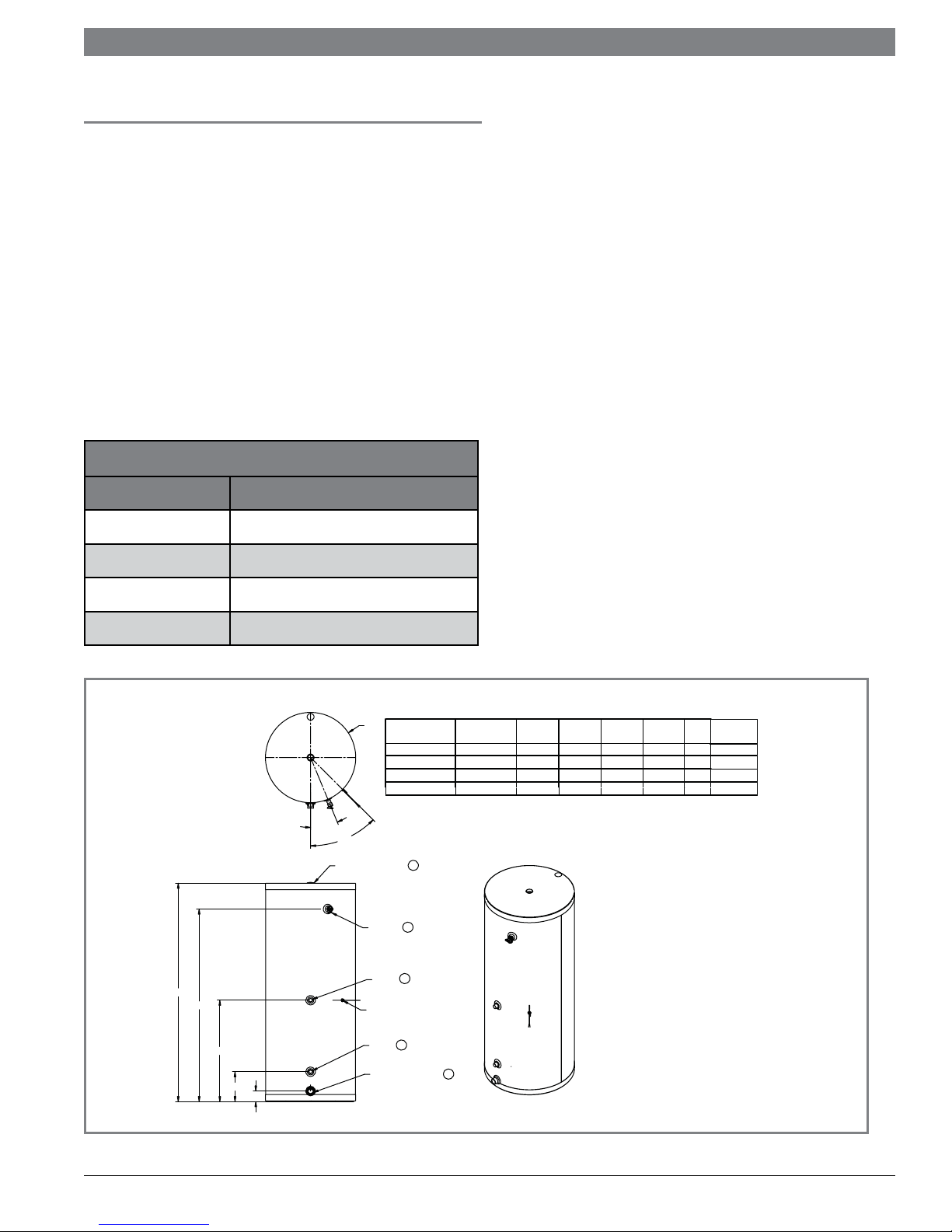
Figure 1-1
“F”
PART NO.
SST150-40
SST250-65
SST300-80
SST450-119
NOTES:
22.5°
45°
1” NPT (SEE NOTE 1)
“E”
“D”
“C”
“B”
“A”
1. 1-1/2” NPT ON SST MOD ELS.
2
1
3/4” NPT
3
1” NPT
AQUASTAT/SENSOR WELL
4
1” NPT
1” NPT (SEE NOTE 1)
“A”
(in.)
3
3 1/4
3 1/4
3 1/4
5
“B”
(in.)
8 1/4
9 1/4
9 1/4
9 1/4
SST150 - SST450
25 1/4
31 3/4
“D”
“C”
(in.)
(in.)
48 1/2
28
52 1/2
28
61 3/4
60 1/4
1. RELIEF VALVE CONNECTION
2. HOT WATER OUTLET
3. BOILER WATER IN
4. BOILER WATER OUT
5. DRAIN/COLD WATER INLET
“E”
(in.)
56
60
70
69
WEIGHT
“F”
FULL OF WATER
(in.)
(lbs.)
20
24
24
28
515
820
921
1268
6 |
Indirect Fired Water Heaters Installation and Operating Manual
2 Pre-installation
Installation & Operating Manual
1. The installation must conform to the instructions in this
manual and all applicable local, state, provincial, and
national codes, laws, regulations, and ordinances.
Installations in Canada must conform to B149.2
Installation Code.
2. Be certain the domestic water supply to the tank has
physical and chemical characteristics that fall within the
limits shown in Table 2A. Where questions exist as to
the composition of the water on the job, a qualied
water treatment expert should be consulted.
CAUTION
Water with characteristics outside the limits shown in
Table 2A may severely shorten the life of the tank due
to corrosion. Damage to tanks in such cases is not
covered under warranty.
3. Read and understand all installation requirements in
this manual.
Water Chemistry Requirements Table 2A
Water used in the tank must have characteristics falling
within the following limits:
Characteristic Min. Max.
Ph 6.0 8.0
Locating the Tank
1. Choose a location for your water heater centralized to
the piping system. You must also locate the SST water
heater where it will not be exposed to freezing
temperatures. Additionally, you will need to place the
water heater so that the controls, drain, and inlet/
outlets are easily accessible. This appliance must not be
installed outdoors, as it is certied as an indoor
appliance, and must also be kept vertical on a level
surface.
2. Keep distance between boiler and water heater to a
minimum to:
a. reduce piping heat loss
b. provide minimal friction loss
3. Figure 1-1 on page 6 shows the weights of all the tanks
lled with water. Make sure that the location chosen for
the tank is capable of supporting it.
CAUTION
This appliance must be placed where leakage from
the relief valve, leakage from the related piping, or
leakage from the tank or connections, will not result
in damage to the surrounding areas, or to the lower
floors of the building. A water heater should always
be located in an area with a floor drain or installed in
a drain pan suitable for water heaters. The
manufacturer shall not be held liable for any such
water damage.
Chloride (PPM) -- 80
4. The tank may be located some distance from the boiler
provided the pump is designed to provide the ow
called for in Table 3B - Pressure Drop Values, through
the coil. Also, the further the tank is from the boiler, the
longer the response of the boiler will be to a call from
the tank zone. Insulate piping between the boiler and
the tank.
WARNING
Failure to properly support the tank could result in
property damage or personal injury.
Recommended Clearances
The installation location must provide adequate clearances
for servicing and proper operation of the water heater. A
12 inch vertical clearance is recommended from the top of
the water heater. A zero clearance is allowed for the sides
of the water heater. However, boiler and servicing
clearances must be gured when locating the water
heater.
Indirect Fired Water Heaters Installation and Operating Manual
| 7
Installation & Operating Manual
3 Boiler Side Piping
Figures 3-1 thru 3-4 show typical boiler side piping for
several common situations. Regardless of which system is
used it is imperative that the ow rates called for in Table
3B are developed through the coil. This requires properly
sized piping and a properly sized pump. The system shown
in FIG’s 3-1 thru 3-4 are described below:
DHW Prioritization
This piping system is designed to provide direct hot water
priority over the other zones in the heating system. When
there is a Domestic Hot Water (DHW) call for heat, the
controller will shut off the boiler circulator and activate
the domestic hot water circulator. Once the DHW demand
is satised, the boiler circulator will be readjusted as
demand requires. The circulator must be large enough to
move the boiler water through the coils. The
recommended piping for a DHW priority system is
depicted in FIG. 3-1
Zone with Circulator to Aquastat
This system is like the circulator zone system on a straight
heat job except that one of the zones goes to the tank
instead of radiation. As on any circulator zone system
check valves should be installed in each zone to prevent
unwanted circulation through zones which are not calling
for heat. Figure 3-2 illustrates typical circulator zone
piping.
Zone with Valve to Aquastat
As with the circulator zone system, this system is just like
a standard heating zone system except that one of the
zones is connected to the tank coil as shown in FIG. 3-3.
The system circulator must be large enough to move boiler
water through the coil regardless of the ow rate required
through the heating zones.
.
Multiple Tank Connections (Boiler Side)
Multiple tank installations must be done in the “reversereturn” manner. The reason for this is to create the same
pressure drop (and therefore, the same ow) through the
coil of each tank. The boiler manifold piping must be sized
so that each coil has the ow rate called for in Table 3B.
Because the pressure drop through tank coils varies from
size to size, it is hard to predict the ow rate that will be
developed through each coil when two tanks of different
sizes are placed in the same manifold. For this reason it is
best not to mix tanks of different sizes in the same zone if
their recovery is critical.
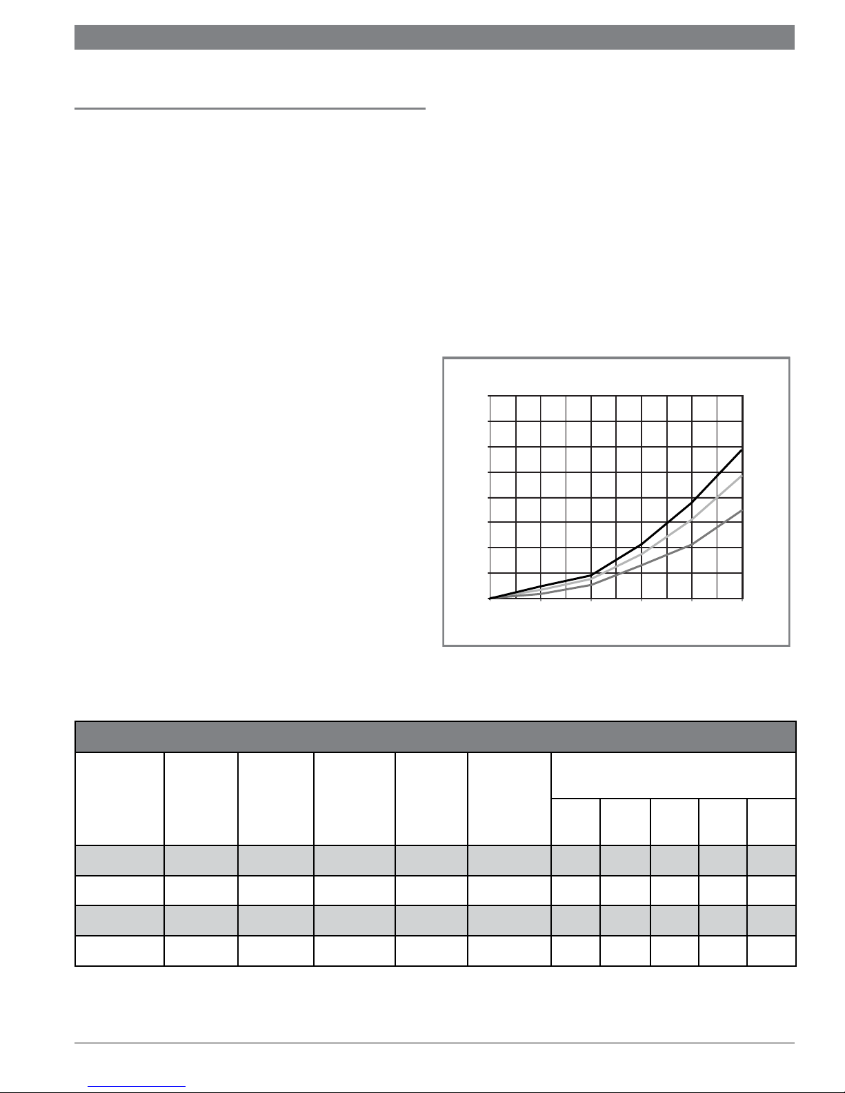
Pressure Drop Chart Table 3A
16
14
12
10
8
6
Head Loss (Ft. of Hd.)
4
2
0
0 5 8 12 16 20
SST450-119
SST250-65/
SST300-80
SST150-40
Flow Rate
Pressure Drop Values Table 3B
Water
Outlet
(IN)
Model
Water
Inlet
(IN)
SST150-40 1 1 1 30.8 10.0 0.41 1.04 2.34 4.16 6.49
SST250-65 1.5 1.5 1 41.5 13.5 0.61 1.57 3.53 6.27 9.80
SST300-80 1.5 1.5 1 41.5 13.5 0.61 1.57 3.53 6.27 9.80
SST450-119 1.5 1.5 1 67.3 22.0 0.73 1.87 4.22 7.50 11.71
8 |
Coil
Connection
(IN)
Pressure Drop (FT/HD)
Coil
Length
(FT)
Surface
area
(SQ-FT)
5
GPM8 GPM
12
GPM
16
GPM
Indirect Fired Water Heaters Installation and Operating Manual
20
GPM
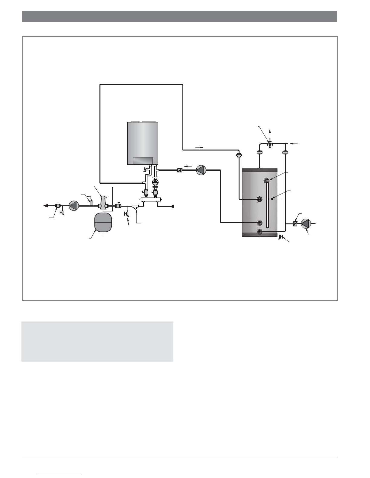
TO
SYSTEM
BALL VALVE
(TYPICAL)
SEPARATOR
SYSTEM SUPPLY
SENSOR
SYSTEM
CIRCULATOR
EXPANSION
TANK
AIR
DRAIN
POINT
GB 142
BOILER
Y-STRAINER
(RECOMMENDED)
FROM
SYSTEM
Installation & Operating Manual
HOT
WATER
OUT
COLD
WATER
IN
PRESSURE RELIEF
VALVE
TANK SENSOR /
AQUASTAT
CHECK VALVE
RECIRCULATION
DRAIN
( FIELD SUPPLY )
PUMP
DOMESTIC
HOT WATER
CIRCULATOR
ANTI-SCALD
MIXING VALVE
SST series tank
Figure 3-1 GB142 Boiler Low Loss Header piping
NOTICE
Please note that these illustrations are meant to show
system piping concept only, the installer is
responsible for all equipment and detailing required
by local codes.
Indirect Fired Water Heaters Installation and Operating Manual
| 9
 Loading...