

Bosch SPX5ES55UC/19, SPX5ES55UC/20, SPX5ES55UC/14, SPX5ES55UC/07, SPX5ES55UC/06 Installation Guide
...
0"3
O_
0
0
0
03
Important Safety instructions
To avoid possible injury or property damage, OBSERVE
ALL WARNINGS AND CAUTIONS.
These instructions are intended for use by qualified
installers only. The dishwasher must be installed by a
qualified service technician or installer.
, In addition to these instructions, the dishwasher
shall be installed to meet all electrical and plumb-
ing codes and ordinances (both national and local).
Read these installation instructions completely and
follow them carefully. They will save you time and ef-
fort and help to ensure safety and optimum dishwasher
performance.
IMPORTANT
, The dishwasher drain hose must be installed with
a portion of it at least 20" (508mm) off the cabinet
floor; otherwise the dishwasher may not drain prop-
erly.
Inspect the Dishwasher
After unpacking the dishwasher and prior to installation,
thoroughly inspect the dishwasher for possible freight
or cosmetic damage. Report any damage immediately.
Cosmetic defects must be reported within 30 days of
installation.
NOTE: Do not discard any bags or items that come
with the original package until after the entire installation
has been completed.
This dishwasher is intended for indoor residential
use only, and should not be used in commercial
food service establishments.
NEW INSTALLATION - If the dishwasher is a new
installation, most of the work must be done before
the dishwasher is moved into place.
REPLACEMENT - If the dishwasher is replacing
another dishwasher, check the existing dishwasher
connections for compatibility with the new
dishwasher, and replace parts as necessary.
, This appliance has been found to be in compliance
with CAN/CSA-C22.2 No. 167/UL 749. It is the
responsibility of the owner and the installer to
determine if additional requirements and standards
apply in specific installations.
, Not for outdoor use.
A
Avoiding General Hazards
Do not use the dishwasher until it is completely
installed. When opening the door on an uninstalled
dishwasher, carefully open the door while supporting
the rear of the unit. Failure to follow this warning can
cause the dishwasher to tip over and result in serious
injury.
Before installing the "L"-shaped supplied countertop
mounting brackets (select models), decide which
method will be used to secure the dishwasher into its
opening. Once these mounting brackets are installed
on the dishwasher, removing them is difficult and will
damage the mounting brackets and the dishwasher.
in some conditions, hydrogen gas can form in a hot
water system that has not been used for weeks.
Hydrogen gas is explosive.
Before filling a dishwasher from a system that has
been off for weeks, run the water from a nearby faucet
in a well ventilated area until there is no sound or evi-
dence of gas.
Temperatures required for soldering and sweating will
damage the dishwasher's base and water inlet valve.
If plumbing lines are to be soldered or sweated, keep
the heat source at least 6" (152.4 mm) away from the
dishwasher's base and water inlet valve.
Removing any cover or pulling the dishwasher from the
cabinet can expose hot water connections, electrical
power and sharp edges or points. Handle with care.
Avoiding Electrical Shock/Fire Hazards .._.
Do not allow the electrical and water supply lines to
touch. Separate channels are provided under the
dishwasher.
Do not work on an energized circuit. Doing so could
result in serious injury or death. Only qualified electri-
cians should perform electrical work. Do not attempt
any work on the dishwasher electric supply circuit
until you are certain the circuit is de-energized.
Make sure electrical work is properly installed. There
should be no loose electrical connections. Ensure all
electrical connections are properly made.
The customer has the responsibility of ensuring that the
dishwasher electrical installation is in compliance with
all national and local electrical codes and ordinances.
The dishwasher is designed for an electrical supply
of 120V, 60 Hz, AC, connected to a dishwasher-
dedicated, properly grounded electrical circuit with a
fuse or breaker rated for 15 amps. Electrical supply
conductors shall be a minimum #14 AWG copper only
wire rated at 75°C (167°F) or higher.
This appliance must be connected to a grounded metal,
permanent wiring system, or an equipment-grounding
conductor must be run with the circuit conductors and
connected to the equipment-grounding terminal or
lead on the appliance. Do not use extension cords.
Avoiding Plumbing/Scalding Hazards'_
Do not perform any work on a charged hot water line.
Serious injury could result. Only qualified plumbershould
perform plumbing work. Do not attempt any work on
the dishwasher hot water supply plumbing until you
are certain the hot water supply is shut off.
Do not over tighten the 90 ° elbow. Doing so may
damage the water inlet valve and cause a water leak.
Temperatures required for soldering and sweating
will damage the dishwasher's water inlet valve. If
plumbing lines are to be soldered or sweated, keep
the heat source at least 6" (152.4 mm) away from the
dishwasher's water inlet valve.
Check local plumbing codes for approved plumbing
procedures and accessories. All plumbing should be
done in accordance with national and local codes.
These instructions depict an installation method for
stainless steel braided hose or PEX hot water supply
lines. If using copper tubing or other material for
water supply, defer to a licensed plumber for proper
installation.
3
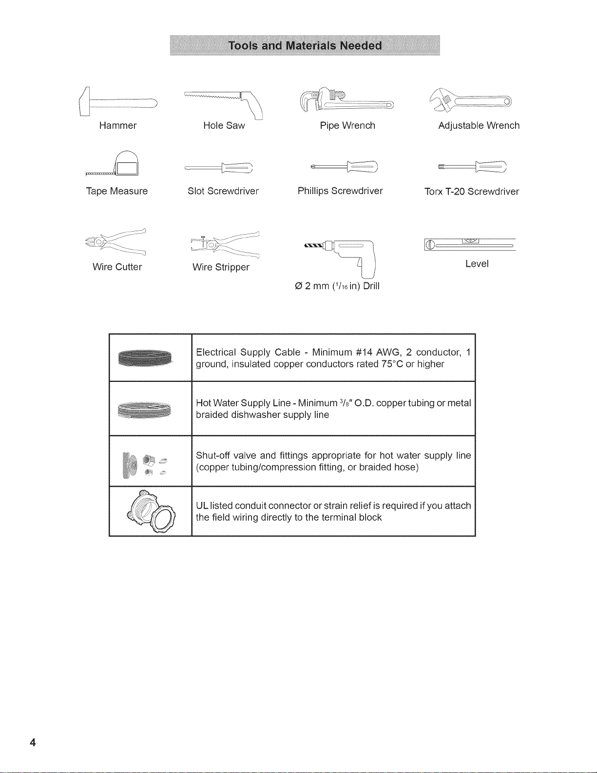
Hammer Hole Saw
Pipe Wrench Adjustable Wrench
Tape Measure
Wire Cutter
Slot Screwdriver
Wire Stripper
Electrical Supply Cable - Minimum #14 AWG, 2 conductor, 1
ground, insulated copper conductors rated 75°C or higher
Hot Water Supply Line - Minimum 3/8"O.D. copper tubing or metal
braided dishwasher supply line
Shut-off valve and fittings appropriate for hot water supply line
(copper tubing/compression fitting, or braided hose)
Phillips Screwdriver
O 2 mm (1/16in) Drill
Torx -[-20 Screwdriver
Level
UL listed conduit connector or strain relief is required ifyou attach
the field wiring directly to the terminal block
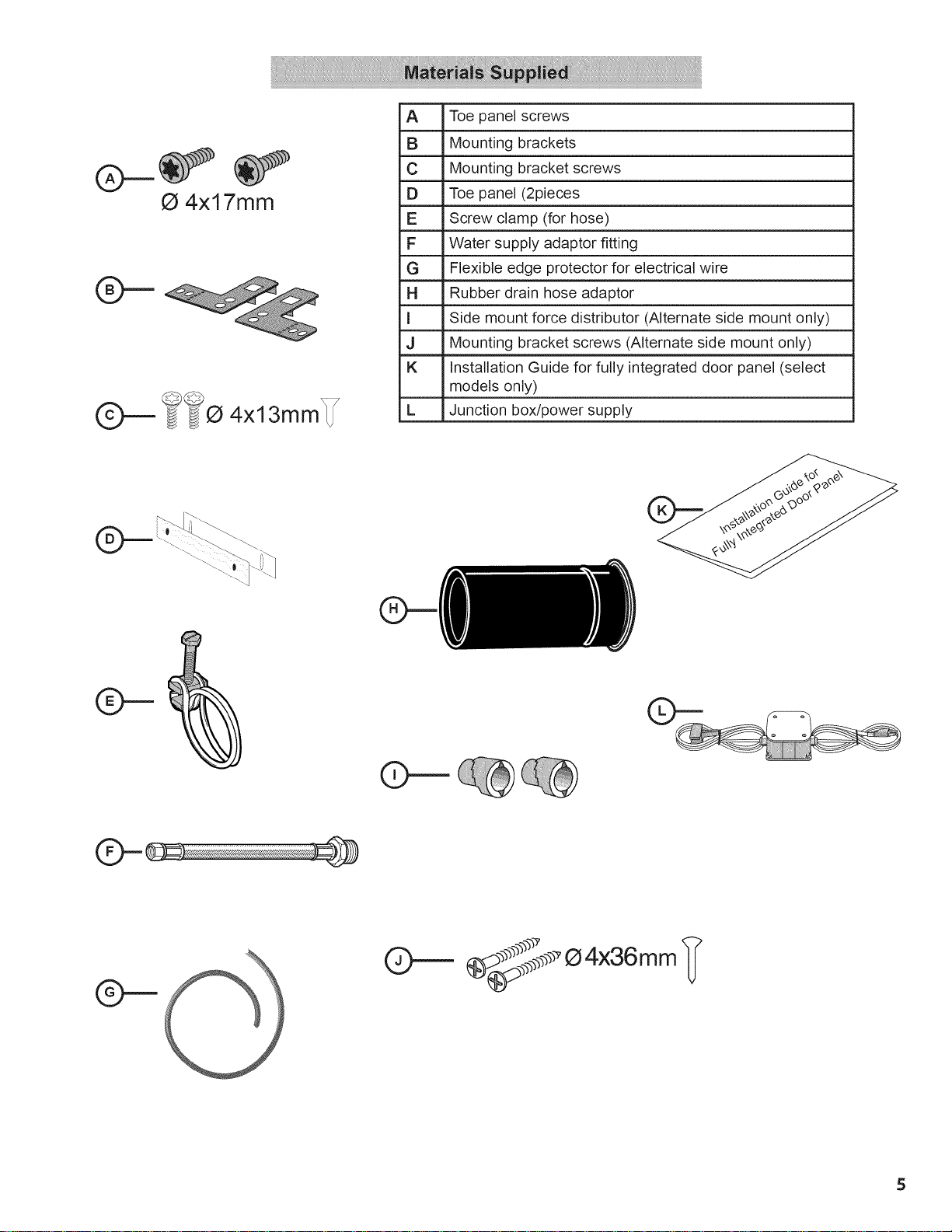
Q 4x17mm
C ? 4x 3r r T
A Toe panel screws
B Mounting brackets
C Mounting bracket screws
D Toe panel (2pieces
E Screw clamp (for hose)
F Water supply adaptor fitting
G Flexible edge protector for electrical wire
H Rubber drain hose adaptor
I Side mount force distributor (Alternate side mount only)
J Mounting bracket screws (Alternate side mount only)
K Installation Guide for fully integrated door panel (select
models only)
L Junction box/power supply
_:p_p__._¢__Q4x36mm_
5
Avoid Scalding or Electrical Shock Hazard!
Make sure the water supply and electrical supply
are shut off before installation or service.
NOTE: This dishwasher is designed to be enclosed on the
top and both sides by standard residential kitchen cabinetry.
Select a location as close to the sink as possible for easy
access to water supply and drain lines.
For proper dishwasher operation and appearance, ensure
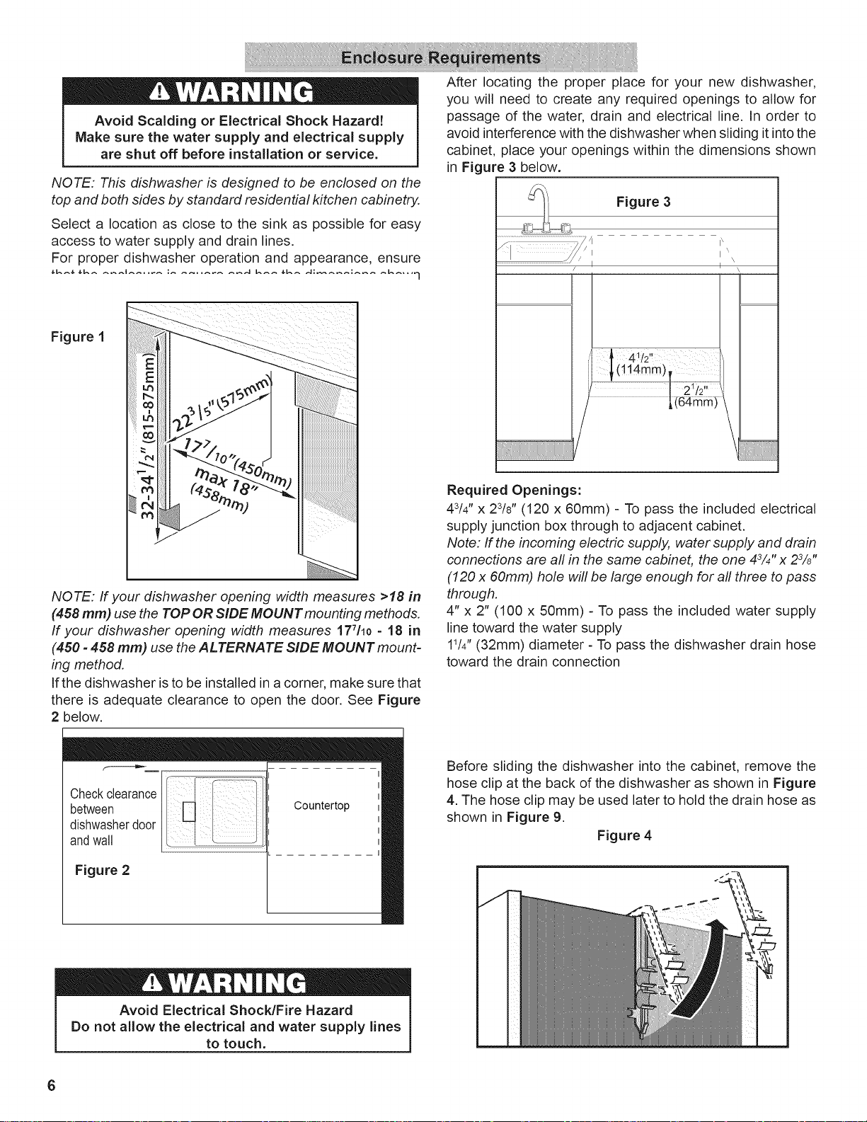
Figure 1
NOTE: If your dishwasher opening width measures >18 in
(458 mm) use the TOP OR SIDE MOUNT mounting methods.
If your dishwasher opening width measures 177/10=18 in
(450 =458 mm) use the ALTERNATE SIDE MOUNT mount-
ing method.
If the dishwasher is to be installed in a corner, make sure that
there is adequate clearance to open the door. See Figure
2 below.
After locating the proper place for your new dishwasher,
you will need to create any required openings to allow for
passage of the water, drain and electrical line. In order to
avoid interference with the dishwasher when sliding it into the
cabinet, place your openings within the dimensions shown
in Figure 3 below.
Figure 3
Z _/ p
I // i I'
...................................................................../ I I N\
/ _ 4!/2" '/
i (114mm)
i ........... I
l,(64mrflr_
Required Openings:
43/4"x 23/8" (120 x 60mm) - To pass the included electrical
supply junction box through to adjacent cabinet.
Note: If the incoming electric supply, water supply and drain
connections are all in the same cabinet, the one 43/4"x 23/8"
(120 x 60mm) hole will be large enough for all three to pass
through.
4" x 2" (100 x 50mm) - To pass the included water supply
line toward the water supply
11/4"(32mm) diameter - To pass the dishwasher drain hose
toward the drain connection
between /
Chockc,ea,a0c:
dishwasherdoor /
andwall [ ..................................................
Figure 2
Avoid Electrical Shock/Fire Hazard
Do not allow the electrical and water supply lines
to touch.
6
Countertop
Before sliding the dishwasher into the cabinet, remove the
hose clip at the back of the dishwasher as shown in Figure
4. The hose clip may be used later to hold the drain hose as
shown in Figure 9.
Figure 4
/
Electrical Preparation
Avoid Electrical Shock Hazard
Do not work on an energized circuit. Doing so
could result in serious injury or death. Only
qualified electricians should perform electrical
work. Do not attempt any work on the dishwasher
electric supply circuit until you are certain the
circuit is de=energized.
Avoid Fire Hazard
Make sure electrical work is properly installed.
Only qualified electricians should perform
electrical work.
Electrical Supply
The customer has the responsibility of ensuring that the
dishwasher electrical installation is in compliance with all
national and local electrical codes and ordinances. The
dishwasher is designed for an electrical supply of 120V,
60 Hz, AC, connected to a dishwasher-dedicated, properly
grounded electrical circuit with afuse or breaker rated for 15
amps. Electrical supply conductors shall be a minimum #14
AWG copper wire rated at 75°C (167°F) or higher.
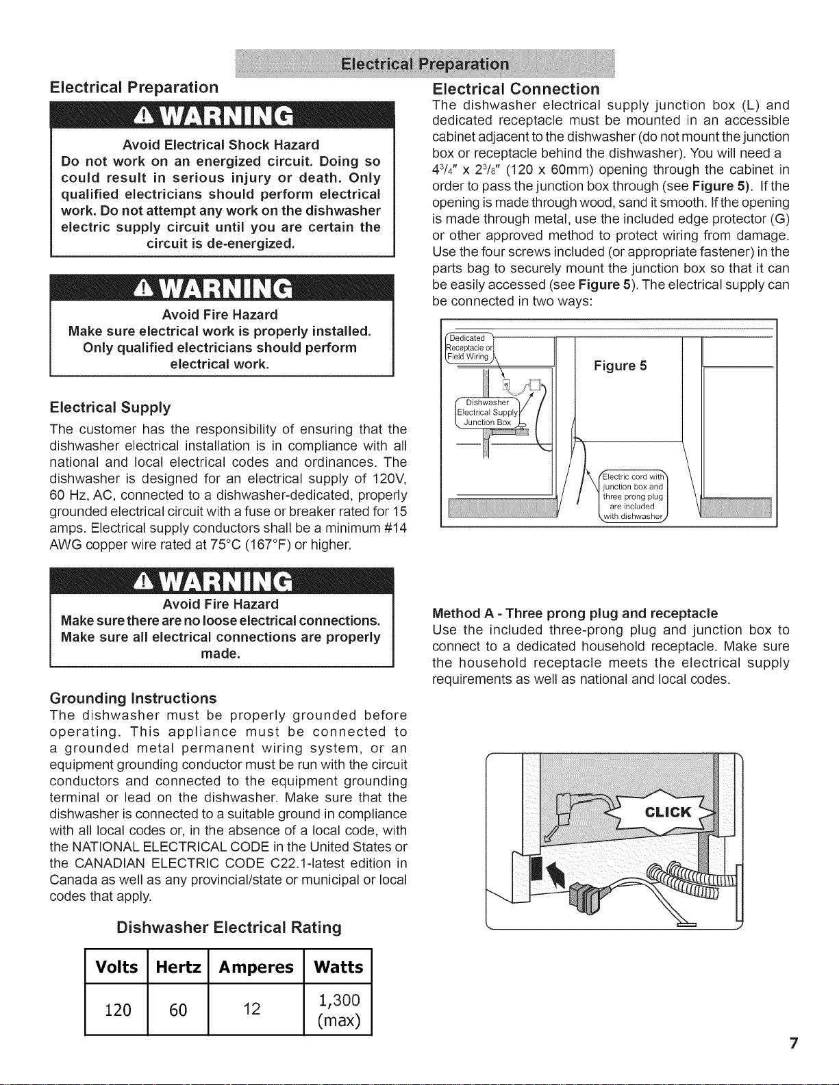
Electrical Connection
The dishwasher electrical supply junction box (L) and
dedicated receptacle must be mounted in an accessible
cabinet adjacent to the dishwasher (do not mount the junction
box or receptacle behind the dishwasher). You will need a
43/4" x 23/8" (120 x 60mm) opening through the cabinet in
order to pass the junction box through (see Figure 5). If the
opening is made through wood, sand itsmooth. Ifthe opening
is made through metal, use the included edge protector (G)
or other approved method to protect wiring from damage.
Use the four screws included (or appropriate fastener) in the
parts bag to securely mount the junction box so that it can
be easily accessed (see Figure 5). The electrical supply can
be connected in two ways:
Figure 5
!_k fElectric cord with"
/
junction box and
three prong plug
are included
\with dishwasher,,
Avoid Fire Hazard
Make sure there are no loose electrical connections.
Make sure all electrical connections are properly
made.
Grounding Instructions
The dishwasher must be properly grounded before
operating. This appliance must be connected to
a grounded metal permanent wiring system, or an
equipment grounding conductor must be run with the circuit
conductors and connected to the equipment grounding
terminal or lead on the dishwasher. Make sure that the
dishwasher is connected to a suitable ground in compliance
with all local codes or, in the absence of a local code, with
the NATIONAL ELECTRICAL CODE in the United States or
the CANADIAN ELECTRIC CODE C22.1-1atest edition in
Canada as well as any provincial/state or municipal or local
codes that apply.
Dishwasher Electrical Rating
Volts Hertz Amperes Watts
Method A - Three prong plug and receptacle
Use the included three-prong plug and junction box to
connect to a dedicated household receptacle. Make sure
the household receptacle meets the electrical supply
requirements as well as national and local codes.
120 60 12 1,300
(max)
7
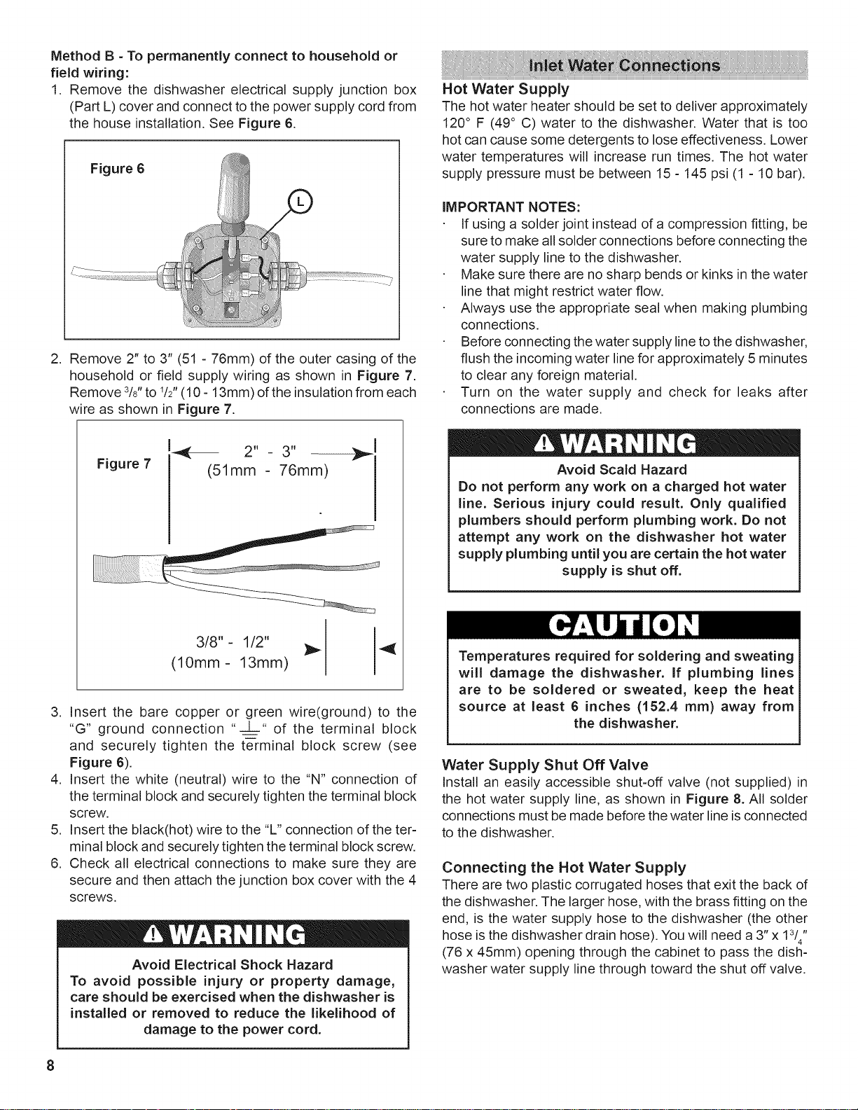
Method B - To permanently connect to household or
field wiring:
I. Remove the dishwasher electrical supply junction box
(Part L) cover and connect to the power supply cord from
the house installation. See Figure 6.
Figure 6
,
Remove 2" to 3" (51 - 76mm) of the outer casing of the
household or field supply wiring as shown in Figure 7.
Remove 3/8"to 1/2"(10 - 13mm) of the insulation from each
wire as shown in Figure 7.
I
Figure 7
-,_-- 2" - 3" ---_,J,
(51ram - 76ram)
I
Hot Water Supply
The hot water heater should be set to deliver approximately
120° F (49° C) water to the dishwasher. Water that is too
hot can cause some detergents to lose effectiveness. Lower
water temperatures will increase run times. The hot water
supply pressure must be between 15 - 145 psi (1 - 10 bar).
IMPORTANT NOTES:
If using a solder joint instead of a compression fitting, be
sure to make all solder connections before connecting the
water supply line to the dishwasher.
Make sure there are no sharp bends or kinks in the water
line that might restrict water flow.
Always use the appropriate seal when making plumbing
connections.
Before connecting the water supply line to the dishwasher,
flush the incoming water line for approximately 5 minutes
to clear any foreign material.
Turn on the water supply and check for leaks after
connections are made.
Avoid Scald Hazard
Do not perform any work on a charged hot water
line. Serious injury could result. Only qualified
plumbers should perform plumbing work. Do not
attempt any work on the dishwasher hot water
supply plumbing until you are certain the hot water
supply is shut off.
3/8"- 1/2" }_ 4{
(10mm- 13mm)
3. Insert the bare copper or green wire(ground) to the
"G" ground connection "--L-" of the terminal block
and securely tighten the te-rminal block screw (see
Figure 6).
4. Insert the white (neutral) wire to the "N" connection of
the terminal block and securely tighten the terminal block
screw.
5. Insert the black(hot) wire to the "L" connection of the ter-
minal block and securely tighten the terminal block screw.
6. Check all electrical connections to make sure they are
secure and then attach the junction box cover with the 4
screws.
Avoid Electrical Shock Hazard
To avoid possible injury or property damage,
care should be exercised when the dishwasher is
installed or removed to reduce the likelihood of
damage to the power cord.
Temperatures required for soldering and sweating
will damage the dishwasher. If plumbing lines
are to be soldered or sweated, keep the heat
source at least 6 inches (152.4 ram) away from
the dishwasher.
Water Supply Shut Off Valve
Install an easily accessible shut-off valve (not supplied) in
the hot water supply line, as shown in Figure 8. All solder
connections must be made before the water line isconnected
to the dishwasher.
Connecting the Hot Water Supply
There are two plastic corrugated hoses that exit the back of
the dishwasher. The larger hose, with the brass fitting on the
end, is the water supply hose to the dishwasher (the other
hose is the dishwasher drain hose). You will need a 3" x 13//'
(76 x 45ram) opening through the cabinet to pass the dish-
washer water supply line through toward the shut off valve.
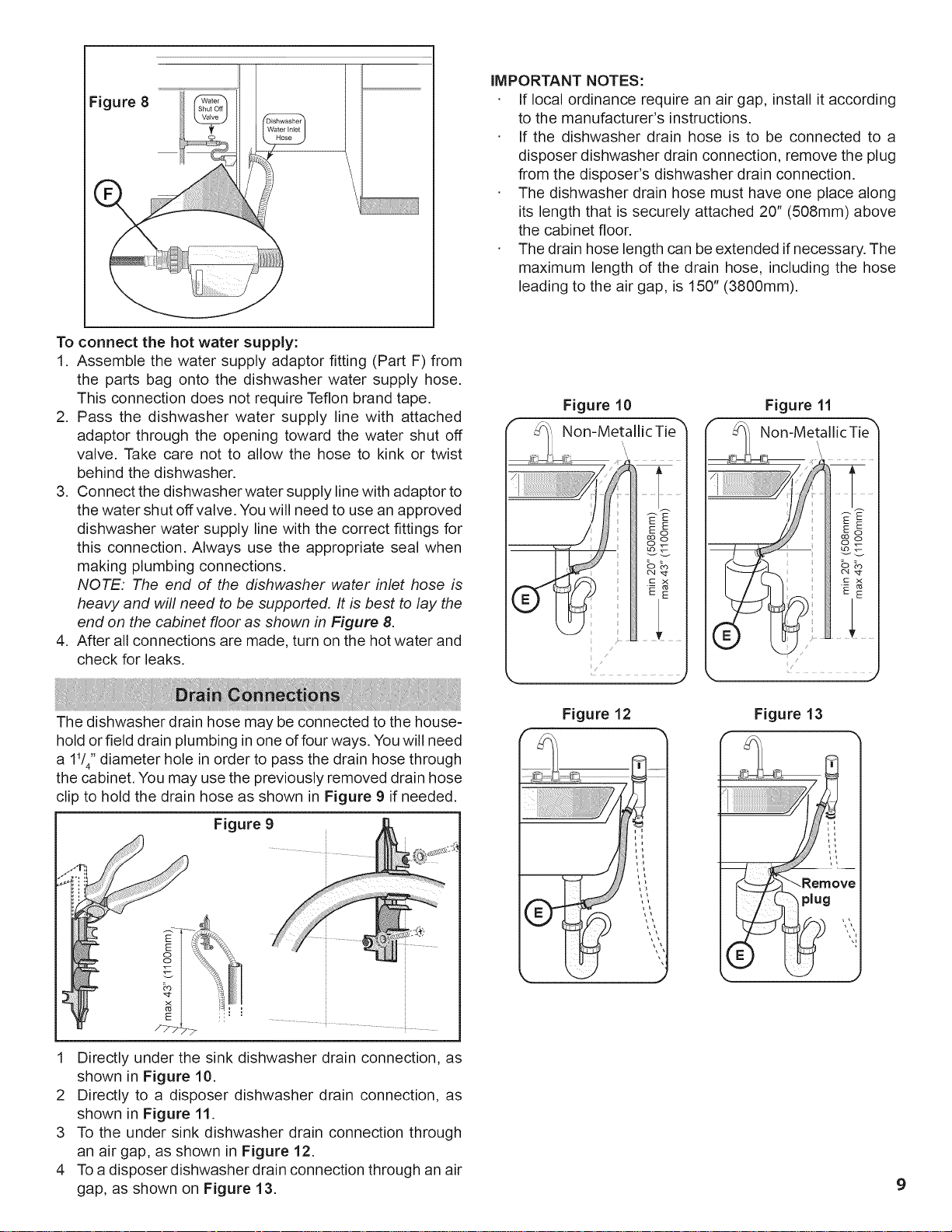
Figure 8
To connect the hot water supply:
1. Assemble the water supply adaptor fitting (Part F) from
the parts bag onto the dishwasher water supply hose.
This connection does not require Teflon brand tape.
2. Pass the dishwasher water supply line with attached
adaptor through the opening toward the water shut off
valve. Take care not to allow the hose to kink or twist
behind the dishwasher.
3. Connect the dishwasher water supply line with adaptor to
the water shut off valve. You will need to use an approved
dishwasher water supply line with the correct fittings for
this connection. Always use the appropriate seal when
making plumbing connections.
NOTE: The end of the dishwasher water inlet hose is
heavy and will need to be supported. It is best to lay the
end on the cabinet floor as shown in Figure 8.
4. After all connections are made, turn on the hot water and
check for leaks.
iMPORTANT NOTES:
If local ordinance require an air gap, install it according
to the manufacturer's instructions.
If the dishwasher drain hose is to be connected to a
disposer dishwasher drain connection, remove the plug
from the disposer's dishwasher drain connection.
The dishwasher drain hose must have one place along
its length that is securely attached 20" (508mm) above
the cabinet floor.
The drain hose length can be extended if necessary. The
maximum length of the drain hose, including the hose
leading to the air gap, is 150" (3800mm).
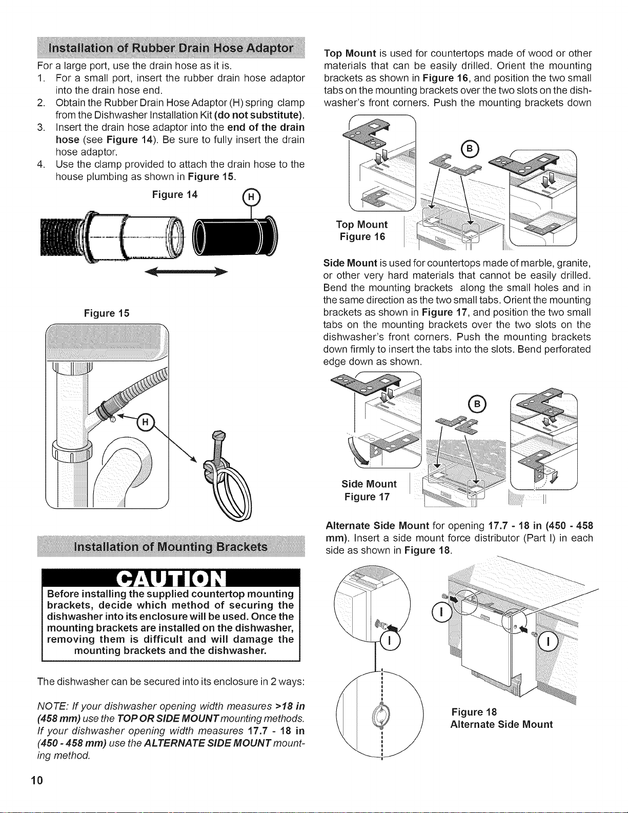
Figure 10 Figure 11
..................... j
The dishwasher drain hose may be connected to the house-
hold or field drain plumbing in one of four ways. You will need
a 11/4'' diameter hole in order to pass the drain hose through
the cabinet. You may use the previously removed drain hose
clip to hold the drain hose as shown in Figure 9 if needed.
Figure 9
E
E
oo
.................... i .......................... i ..........
Directly under the sink dishwasher drain connection, as
shown in Figure 10.
2 Directly to a disposer dishwasher drain connection, as
shown in Figure 11.
3 To the under sink dishwasher drain connection through
an air gap, as shown in Figure 12.
4 To a disposer dishwasher drain connection through an air
gap, as shown on Figure 13.
Figure 12
Figure 13
9
For a large port, use the drain hose as it is.
1. For a small port, insert the rubber drain hose adaptor
into the drain hose end.
2. Obtain the Rubber Drain Hose Adaptor (H) spring clamp
from the Dishwasher Installation Kit (do not substitute).
3. Insert the drain hose adaptor into the end of the drain
hose (see Figure 14). Be sure to fully insert the drain
hose adaptor.
4. Use the clamp provided to attach the drain hose to the
house plumbing as shown in Figure 15.
Figure 14 (_
Figure 15
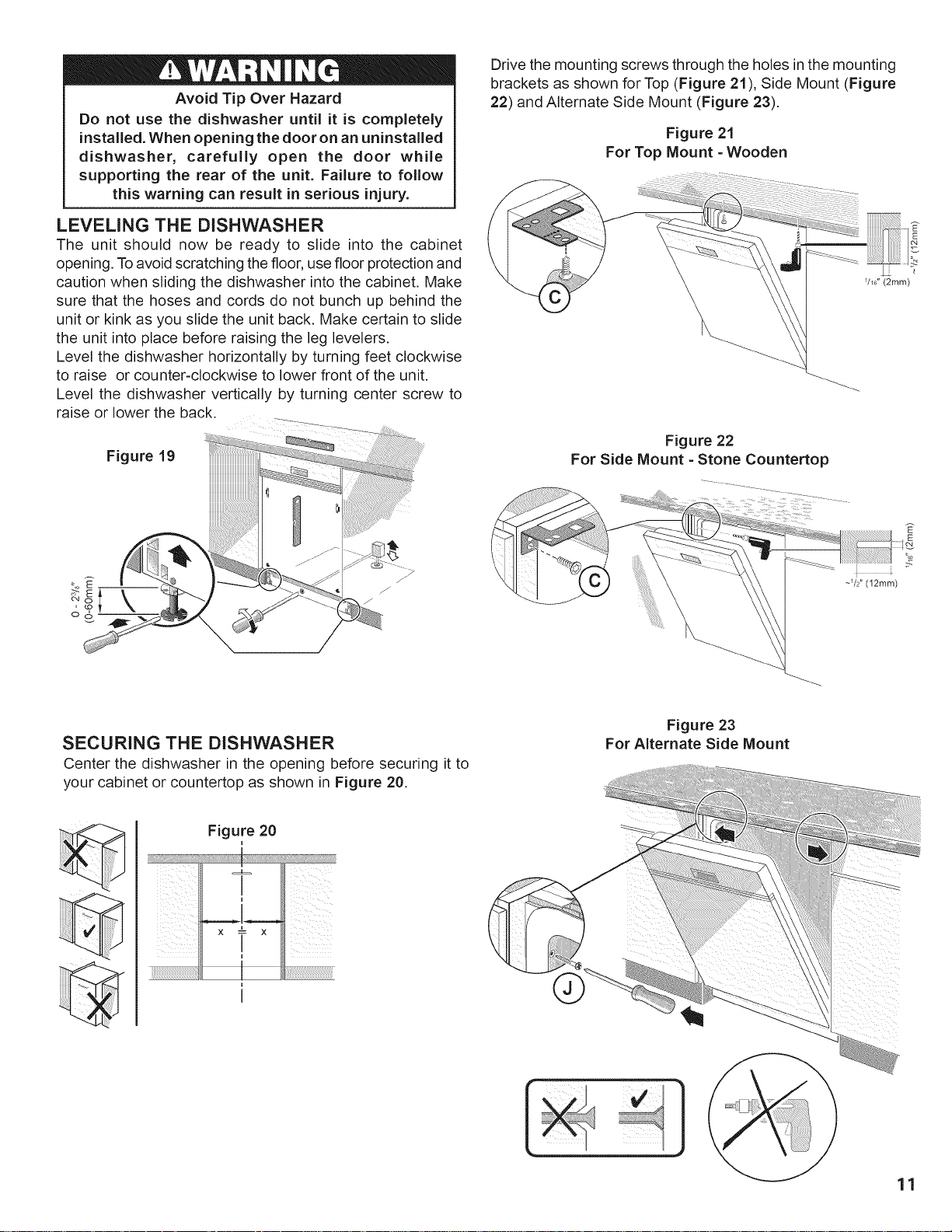
Top Mount is used for countertops made of wood or other
materials that can be easily drilled. Orient the mounting
brackets as shown in Figure 16, and position the two small
tabs on the mounting brackets over the two slots on the dish-
washer's front corners. Push the mounting brackets down
®
Top Mount
Figure 16
Side Mount is used for countertops made of marble, granite,
or other very hard materials that cannot be easily drilled.
Bend the mounting brackets along the small holes and in
the same direction as the two small tabs. Orient the mounting
brackets as shown in Figure 17, and position the two small
tabs on the mounting brackets over the two slots on the
dishwasher's front corners. Push the mounting brackets
down firmly to insert the tabs into the slots. Bend perforated
edge down as shown.
Before installing the supplied countertop mounting
brackets, decide which method of securing the
dishwasher into its enclosure will be used. Once the
mounting brackets are installed on the dishwasher,
removing them is difficult and will damage the
mounting brackets and the dishwasher.
The dishwasher can be secured into its enclosure in 2ways:
®
Side Mount
Figure 17
Alternate Side Mount for opening 17.7 - 18 in (450 - 458
mm). Insert a side mount force distributor (Part I) in each
side as shown in Figure 18.
NOTE: If your dishwasher opening width measures >18 in
(458 mm) use the TOP OR SiDE MOUNT mounting methods.
If your dishwasher opening width measures 17.7 - 18 in
(450 =458 ram) use the ALTERNATE SIDE MOUNT mount-
ing method.
10
Figure 18
Alternate Side Mount
Avoid Tip Over Hazard
Do not use the dishwasher until it is completely
installed. When opening the door on an uninstalled
dishwasher, carefully open the door while
supporting the rear of the unit. Failure to follow
this warning can result in serious injury.
LEVELING THE DISHWASHER
The unit should now be ready to slide into the cabinet
opening. Toavoid scratching the floor, use floor protection and
caution when sliding the dishwasher into the cabinet. Make
sure that the hoses and cords do not bunch up behind the
unit or kink as you slide the unit back. Make certain to slide
the unit into place before raising the leg levelers.
Level the dishwasher horizontally by turning feet clockwise
to raise or counter-clockwise to lower front of the unit.
Level the dishwasher vertically by turning center screw to
raise or lower the back.
Figure 19
Drive the mounting screws through the holes in the mounting
brackets as shown for Top (Figure 21), Side Mount (Figure
22) and Alternate Side Mount (Figure 23).
Figure 21
For Top Mount - Wooden
_/E6"(2ram)
Figure 22
For Side Mount - Stone Countertop
SECURING THE DISHWASHER
Center the dishwasher in the opening before securing it to
your cabinet or countertop as shown in Figure 20.
Figure 20
X t X
/
i
i_:;_:_:_!i_!i_!i_!i_!i_!i_!i_!i_!i_!i_!i_!i_!i_!i_!i_!i_!i_!i_!i_!i_!i_!i_!i_!i_!i_!i_!i_!i_!i_!i_!i_!i_!i_!::::_!::i:iI
I
I
~_/2" (12ram)
Figure 23
For Alternate Side Mount
11
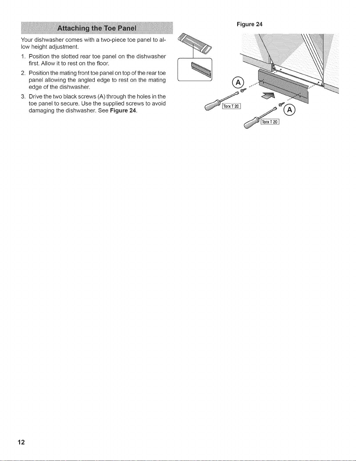
Your dishwasher comes with a two-piece toe panel to al-
low height adjustment.
1. Position the slotted rear toe panel on the dishwasher
first. Allow it to rest on the floor.
2. Position the mating front toe panel on top of the rear toe
panel allowing the angled edge to rest on the mating
edge of the dishwasher,
3. Drive the two black screws (A) through the holes in the
toe panel to secure. Use the supplied screws to avoid
damaging the dishwasher. See Figure 24.
Figure 24
12
 Loading...