

Page 1
273 Branchport Avenue
Long Branch, N.J. 07740
(800) 631-2148
Thank you for using our products
www.wheelockinc.com
INSTALLATION INSTRUCTIONS
3 MESSAGE EXPANDER MODULE (SP4-3MEM)
(FOR SP40/2)
Use this product according to this instruction manual. Please keep this instruction manual for future reference.
MODEL NUMBER:
SP4-3MEM
GENERAL:
The 3 Message Expander Module (SP4-3MEM) is designed to be used with Wheelock’s SP40/2 SAFEPATH4 panel. The SP4- 3MEM provides a
means of expanding the number of digital voice messages by as many as three.
One SP4-3MEM can be connected to the SP40/2 panel. It is connected inside the panel enclosure in the center of the SP40/2 motherboard.
The SP4-3MEM contains its own microprocessor and digital memory chip. It can playback up to three prerecorded digital messages. The digital
voice memory chip memory capacity is divided into three 20-second sections. Each section corresponds to one of the corresponding input circuits. If
the length of a message exceeds the 20 seconds, it will continue playback into the next section. The next section cannot contain a new message. The
exception is the third section, which will stop playback at the end of the 20 seconds. The following table describes the playback feature.
NOTE: All CAUTIONS and WARNINGS are identified by the symbol . All warnings are printed in bold capital letters.
WARNING: PLEASE READ THESE INSTRUCTIONS CAREFULLY BEFORE USING THIS PRODUCT. FAILURE TO COMPLY
WITH ANY OF THE FOLLOWING INSTRUCTIONS, CAUTIONS AND WARNINGS COULD RESULT IN IMPROPER
APPLICATION, INSTALLATION AND/OR OPERATION OF THESE PRODUCTS IN AN EMERGENCY SITUATION, WHICH
COULD RESULT IN PROPERTY DAMAGE AND SERIOUS INJURY OR DEATH TO YOU AND/OR OTHERS.
Message 1 Message 2 Message 3
Table 1: Playback Features
3 Message Selection <20 sec <20 sec <20 sec
2 Message Selection >20 sec but <40 sec <20 sec
2 Message Selection <20 sec >20 sec but <40 sec
1 Message Selection >40 sec but < 60 sec
< = symbol for less than
> = symbol for greater than
The digital message chip shall be recorded at Wheelock Inc. The SP40/2 does not have the capability to record messages at the panel. When
purchased a 3 Message Expander Module custom message chip shall be recorded and installed by the manufacturer. The digital message chip cannot
be purchased and installed on site.
The NAC input voltage range for initiating the messages is 8 to 33VDC. The operating voltage on the circuit board is 5VDC. The standby current is
35mA, and the maximum alarm current is 45mA.
The three NAC inputs on the SP4-3MEM provide initiation of the message in the corresponding section on the digital voice message chip. These
inputs have a higher priority than the three messages on the SP40/2. The following is a list in the order of priority on the SP40/2 when the SP43MEM is used:
1. SP40/2 On board Microphone
2. Remote Microphone (SPRM) (Optional)
3. SP4-3MEM IN-A1
4. SP4-3MEM IN-A2
5. SP4-3MEM IN-A3
6. SP40/2 IN1
7. SP40/2 IN2
8. SP40/2 IN3
9. Night Ringer
10. Telephone Page
11. Background Music
Copyright 2004 Wheelock, Inc. All rights reserved.
P84482 D
Sheet 1 of 8
Page 2
MATERIALS:
When the SP4-3MEM is received, the following items shall be included:
One – SP4-3MEM PC board with the message kit already installed.
Two – Male to male 10 pin interconnectors
One – Teflon standoff
One – Screw
One – Pair of wires to connect the SP4-3MEM to the SP40/2
WIRING INSTRUCTIONS:
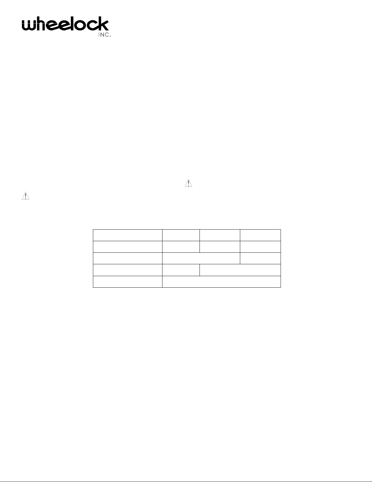
NOTE: The terminal blocks (TB1 and TB2) on the SP4-3MEM are removable. To remove a terminal block, pull the block straight
up from the circuit board as shown in Figure 1. Attach wires to the desired connections, then plug the terminal block back on the
board being careful to match and align the pins.
Figure 1: Removable Terminal Block
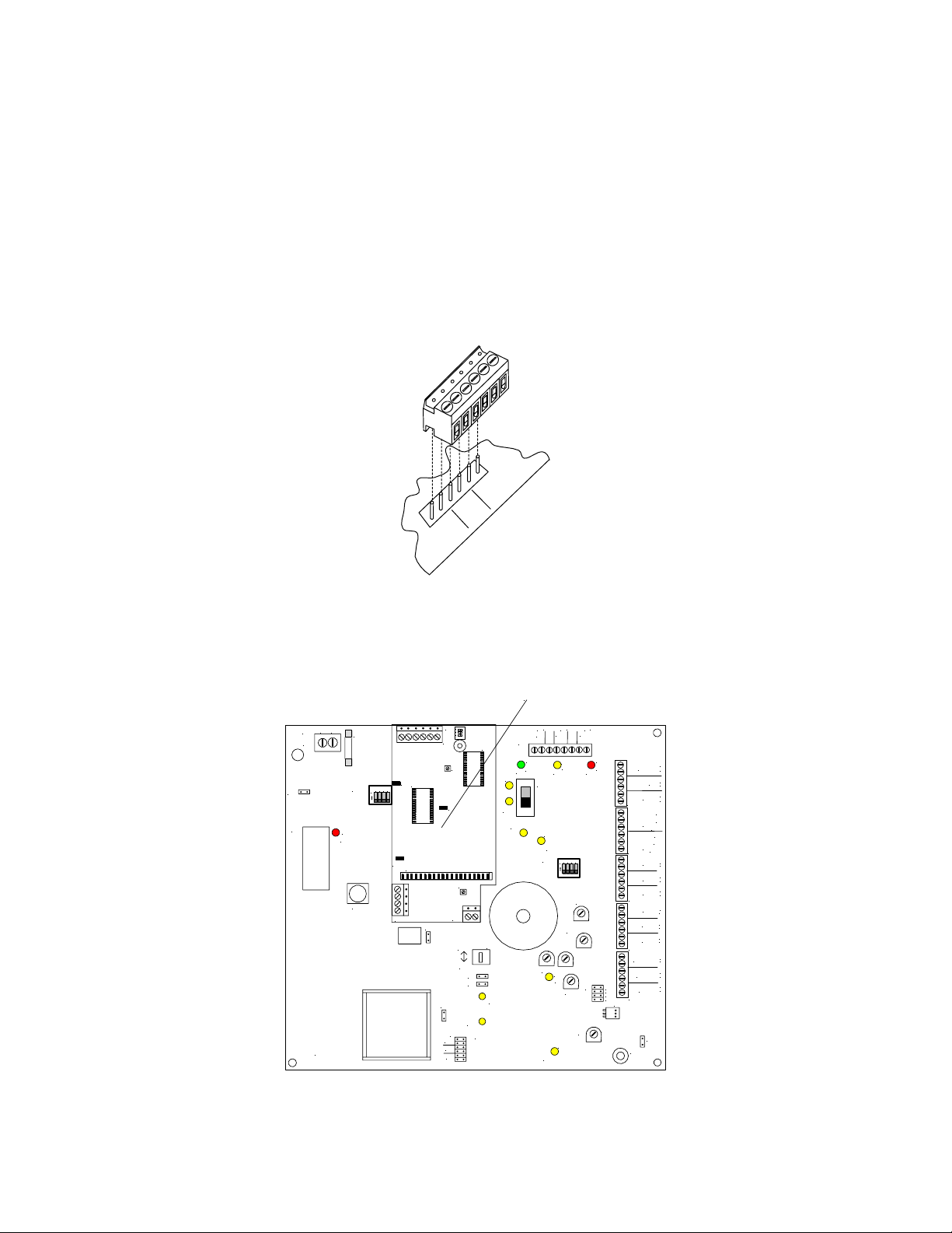
MOUNTING INSTRUCTIONS:
Figure 2 shows the SP4-3MEM mounted to the SP40/2 motherboard. Figure 3 shows the correct mounting procedure
SP4-3MEM
1
O N
L
N
AC
TB7
W1
U8
P84014 REV
RECORD
D34
SW2
MIC1
F2
4
2 3
1
ON
W2
TB2
SW1
32
TB1
W1
R36
U4
W3
J1
R23
TB3
W3
NAC
CC
W5
W4
W7
D58
J4
100V
70V
25V
AUDIO
OPEN
U7
D54
SW4
AUDIO
SHORT
TB1
D11
AC
BAT
D37
Figure 2: SP4-3MEM mounted to the SP40/2 motherboard
AC
GRN
IN
+
SW1
_
_
SW3
D49
D60
D39
STB
OPEN
TONE
_
+
+
24V
BAT
STB
TBL
YEL
RED
D13
D14
3
R
1
2
4
2 3
1
ON
TEL
BGM
AUX
IN
GF
1V
J2
25V
AUX
70V
100V
DV
+
STB OUT
_
+
RET
_
+
STB IN
_
TB2
A
NO
L
NC
M
COM
NO
T
NC
R
B
COM
TB3
+
IN3
_
+
IN2
_
+
IN1
_
TB4
+
NR
_
+
TEL
_
+
BGM
_
TB5
+
AUDIO OUT
_
+
_
CC/NAC
+
_
AUX IN
TB6
J3
W6
E1
.
P84482 D
Sheet 2 of 8
Page 3
STANDOFF
SCREW
1
SW1
O N
32
TB1
U7
W1
R36
U4
W3
W2
10 PIN MALE TO MALE
INTERCONNECTOR (2
L
N
AC
TB7
W1
U8
P84014 REV
RECORD
D34
F2
4
2 3
1
ON
SW2
D22
DV
D35
MIC
AMP
D36
MIC1
W8
)
_
_
+
IN
TB1
AC
GRN
D11
AC
SW1
D9
D10
W2
W3
W7
J4
100V
70V
25V
BAT
D37
STB
SHORT
SW4
NAC
CC
W5
W4
D54
AUDIO
SHORT
D58
AUDIO
OPEN
_
+
+
24V
BAT
STB
TBL
YEL
RED
D13
D14
D39
STB
OPEN
3
R
1
2
SW3
4
2 3
1
ON
TEL
BGM
TONE
D49
AUX
IN
J2
AUX
DV
GF
D60
J1
TB2
+
STB OUT
_
+
RET
_
+
STB IN
_
TB2
A
NO
L
NC
M
COM
NO
T
NC
R
B
COM
TB3
+
IN3
_
+
IN2
_
+
IN1
_
TB4
+
NR
_
+
TEL
_
+
BGM
_
TB5
+
AUDIO OUT
_
+
_
CC/NAC
1V
25V
70V
100V
J3
+
_
AUX IN
TB6
W6
E1
R36
R23
TB3
Figure 3: Shows the correct mounting
1. Remove the mounting screw from the top center of the SP40/2 motherboard. Place screw aside for use in Step 5.
2. Screw the male end of the standoff into the hole from Step 1.
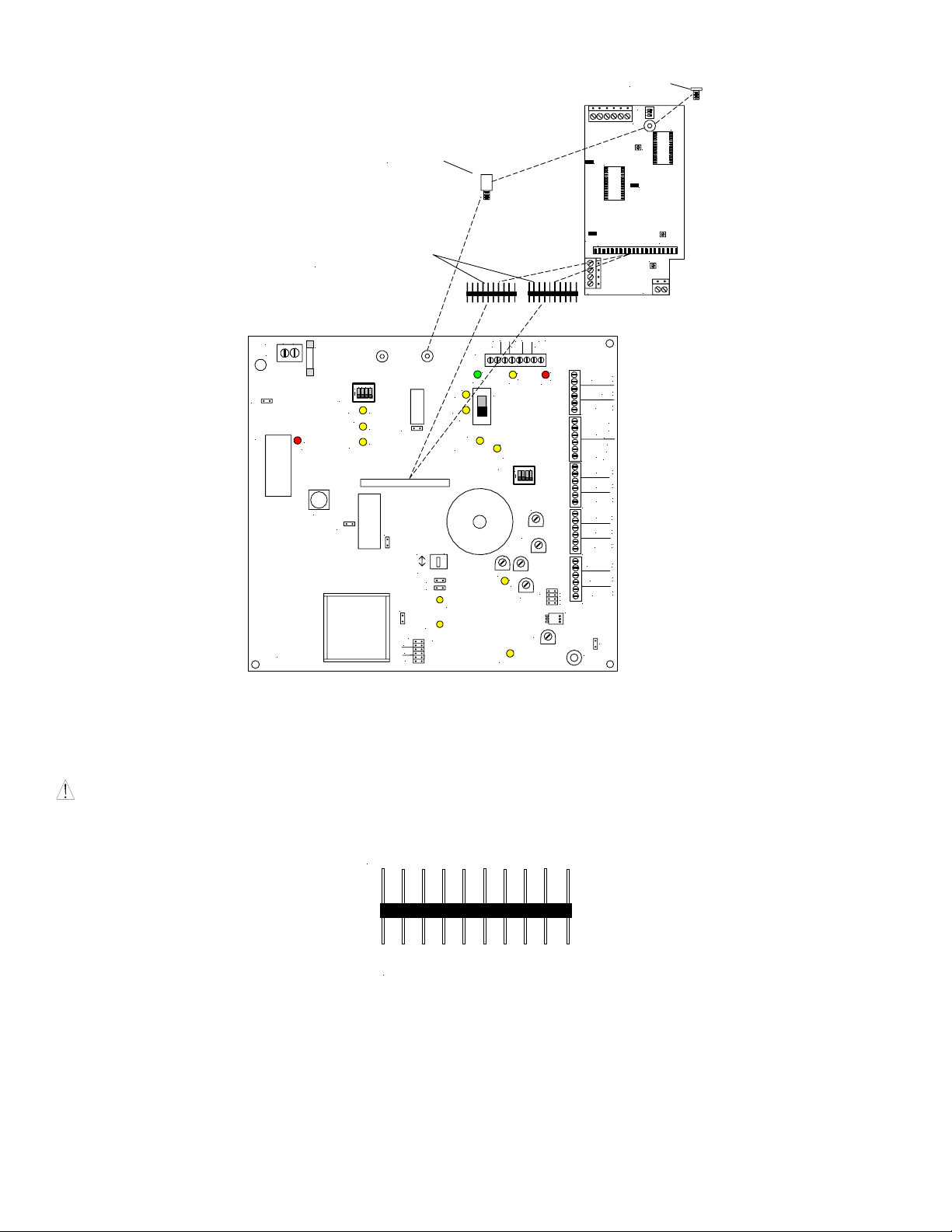
CAUTION: The 10 pin male-to-male interconnector pins are two different lengths. Mount the shorter pins into J1 female
connector on the motherboard.
LONGER PINS CONNECT THROUGH THE
BOTTOM OF THE SP4-3MEM PC BOARD
SHORTER PINS CONNECT TO THE
SP40/2 MOTHERBOARD
Figure 4: 10 pin male-to-make interconnector
3. As shown in Figure 4, connect the short pins on the two 10 pin male-to-male interconnectors to the 20 pin female connector J1 on
the motherboard.
4. Position the bottom of the SP4-3MEM PC board connector J1 over the two 10 pin interconnectors mounted on the SP40/2
motherboard. When all pins are properly aligned, press firmly on the SP4-MEM3 PC board until the board is properly seated.
5. Using the screw removed in Step 1, secure the SP4-3MEM PC board to the SP40/2 motherboard.
P84482 D
Sheet 3 of 8
Page 4

WIRING INSTRUCTIONS:
IN A1
FACP NA C
INPUT
8 TO 33VDC
IN A3
IN A2
W1
W2
1
O N
SW1
2
3
TB1
R36
U4
W3
J1
U7
CC
R23
AUX IN
TB2
TB3
AUX OUT
Figure 5: Wiring Connections
1. Connect NAC (8 to 33VDC) circuits to IN A1, IN A2, and/or IN A3 to play the desired message(s).
2. Connect the AUX OUT on the SP4-3MEM to the AUX IN on the SP40/2 motherboard.
WIRING INSTRUCTION WHEN USED WITH THE REMOTE MICROPHONE (SPRM)
NOTE: When the SP4-3MEM is used, the Remote Microphone (SPRM) shall be connected to the SP4-3MEM PC board and not to
the SP40/2 motherboard.
The Remote Microphone (SPRM) shall be connected to the AUX IN and the CC terminals on TB2 on theSP4-3MEM. It shall not be
connected to the SP40/2 motherboard.
1. Connect the SPRM 24VDC input to the ±24V terminals on TB1of the SP40/2.
2. Connect the AUDIO terminals on the SPRM to the AUX IN terminals on TB2 (SP4-3MEM).
3. Connect the STATUS(CC) terminals on the SPRM to the CC terminals on TB2 (SP4-3MEM).
4. Switch SW4 (NAC/CC) on the SP40/2 to the CC position.
NOTE: The maximum wire length from the SP4-3MEM to the SPRM is 2000 ft.
P84482 D
Sheet 4 of 8
Page 5

1
O N
SW1
32
TB1
R36
W1
U4
W3
J1
R23
TB3
W3
NAC
CC
W5
W4
W7
D58
J4
100V
70V
25V
AUDIO
OPEN
U7
R59
D54
SW4
AUDIO
SHORT
TB1
D11
AC
BAT
D37
REMOTE MICROPHONE
+
24VDC
-
+
STATUS (CC)
-
+
RM AUDIO
-
SW4 NAC/CC
SWITCH
L
N
AC
TB7
W1
U8
654321
P84014 REV
RECORD
D34
SW2
MIC1
F2
4
2 3
1
ON
W2
TB2
Figure 6: Remote Microphone Connections
WIRING SPECIFICATIONS:
Cable Size: NAC inputs accept #12 - #18 American Wire Gauge (AWG).
OPERATING INSTRUCTIONS:
SW1 - STROBE
IN A3
IN A2
W1
U4
ACTIVATION SWITCH
IN A1
1
O N
SW1
32
TB1
R36
W1 - DV FAIL
BACKUP TONE
W3
AC
GRN
_
+
BAT
IN
D13
SW1
D39
STB
OPEN
SW3
ON
TONE
D49
AUX
IN
GF
D60
U7
_
_
+
+
24V
STB
TBL
YEL
D14
R
3
1
2
4
2 3
1
TEL
BGM
J2
AUX
DV
RED
STB OUT
TB2
TB3
TB4
TB5
AUDIO OUT
CC/NAC
1V
AUX IN
25V
70V
TB6
100V
J3
E1
MESSAGE
MEMORY CHIP
R36 - DV
VOLUME ADJUST
STB IN
A
L
M
T
R
B
IN3
IN2
IN1
NR
TEL
BGM
W6
+
_
+
RET
_
+
_
NO
NC
COM
NO
NC
COM
+
_
+
_
+
_
+
_
+
_
+
_
+
_
+
_
+
_
W3 - PRE-ALERT
TONE
W2 - AUX INPUT
SUPERVISION
CC
AUX IN
W2
J1
R59
R23
TB2
TB3
R59 - PRE ALERT
TONE VOLUME
R23 - AUX OUT
VOLUME ADJUST
AUX OUT
Figure 7: 3MEM Setting
P84482 D
Sheet 5 of 8
Page 6

Table 2: 3MEM Settings
Name Function Description
SW1 Strobe Activation Switch
3-position DIP switch. ON position on any or all positions
activates strobe NAC circuit(s) on SP40/2 when corresponding
NAC input is selected.
W1 DV Fail Backup Tone Jumper ON – Code 3 Tone
Jumper OFF – Continuous Tone
W2 Aux Input Supervision Jumper ON – No Remote Microphone (SPRM) installed.
Remove jumper when installing SPRM.
W3 Pre-Alert Tone Jumper ON – Plays DV Fail Backup Tone (two rounds of Code
3 Tone or Continuous) prior to digital voice message from
SP4-3MEM.
INA1, 2 = Code 3
INA3 = Continuous
R23 Aux Out Volume Adjust Adjusts output volume of Remote Microphone (SPRM)
R36 DV Volume Adjust Adjust digital voice message volume
R59 Tone Volume Adjust Adjust pre alert tone volume and DV tone backup volume.
1. Select strobe activation using switch SW1 on the SP4-3MEM
SP40/2
2. Remove jumper W8 on the SP40/2 motherboard. This enables supervision of the SP4-3MEM. See Figure 8.
3. Set Jumper J2 to “1V”.
4. Set switch SW4 to the “CC” position.
5. Insert jumper W5 to disable supervision of the “CC” input terminals on the SP40/2.
_
_
L
N
AC
TB7
W1
U8
F2
RECORD
D34
MIC1
SW2
4
2 3
1
ON
DV
MIC
W2
AMP
W8
W3
W7
100V
70V
25V
NAC
CC
W4
W5
AUDIO
OPEN
AC
BAT
AUDIO
SHORT
STB
SHORT
+
IN
TB1
D11
AC
GRN
SW1
STB
OPEN
SW3
TONE
AUX
GF
_
+
+
24V
BAT
TBL
STB
YEL
RED
3
R
1
2
4
2 3
1
ON
TEL
BGM
IN
AUX
1V
25V
70V
100V
J3
DV
STB OUT
TB2
TB3
TB4
TB5
AUDIO OUT
CC/NAC
AUX IN
TB6
STB IN
A
L
M
T
R
B
IN3
IN2
IN1
NR
TEL
BGM
W6
RET
COM
COM
+
_
+
_
+
_
NO
NC
NO
NC
+
_
+
_
+
_
+
_
+
_
+
_
+
_
+
_
+
_
E1
W8 SP4-3MEM
SUPERVISION
ENABLE
W5 CONTACT
CLOSURE
SUPERVISION
Figure 8: SP40/2 Setting
SW4 NAC/CC
SWITCH
J2 AUXILIARY INPUT
VOLTAGE SELECT
P84482 D
Sheet 6 of 8
Page 7

TROUBLESHOOTING PROCEDURES:
Figure 9 shows the location of the power and trouble LED's on the SP4-3MEM PC board.
1. Insure that the green POWER LED D16 is “ON”. If no LED's are lighted, check the SP40/2 to insure it is on. Turn power off
prior to checking the 20 pin terminal and insuring all pins are properly seated.
2. Verify wiring is correct.
3. Verify jumpers are correct.
4. If the yellow DV TROUBLE LED is “ON”, a Digital Voice Memory Chip (U7) failure is indicated. Also the SP40/2 will
indicate a trouble condition.
5. If the yellow AUX TROUBLE LED is “ON”, a Remote Microphone (SPRM) trouble has occurred. Also the SP40/2 will
indicate a trouble condition. Troubleshoot the SPRM and connecting wiring.
6. A failure of the SP4-3MEM will cause a trouble condition to occur on the SP40/2 turning ON the TROUBLE LED. Turn power
off prior to removing the SP4-3MEM and insure the SP40/2 functions correctly. If the SP40/2 operates properly, replace the
SP4-3MEM with a new one.
1
O N
SW1
32
TB1
U7
R36
W1
U4
D15
W3
D15 DV TROUBLE
(YELLOW)
D14 AUXILIARY
D14
TROUBLE (YELLOW)
D16 POWER ON
(GREEN)
W2
J1
TB2
D16
R59
R23
TB3
Figure 9: 3MEM POWER and TROUBLE LEDS
ANY MATERIAL EXTRAPOLATED FROM THIS DOCUMENT OR FROM WHEELOCK MANUALS OR OTHER
DOCUMENTS DESCRIBING THE PRODUCT FOR USE IN PROMOTIONAL OR ADVERTISING CLAIMS, OR FOR
ANY OTHER USE, INCLUDING DESCRIPTION OF THE PRODUCT'S APPLICATION, OPERATION, INSTALLATION
AND TESTING IS USED AT THE SOLE RISK OF THE USER AND WHEELOCK WILL NOT HAVE ANY LIABILITY
FOR SUCH USE.
P84482 D
Sheet 7 of 8
Page 8

Limited Warranty
Wheelock products must be used within their published specifications and must be PROPERLY specified, applied, installed, operated,
maintained and operationally tested in accordance with these instructions at the time of installation and at least twice a year or more
often and in accordance with local, state and federal codes, regulations and laws. Specification, application, installation, operation,
maintenance and testing must be performed by qualified personnel for proper operation in accordance with all of the latest National
Fire Protection Association (NFPA), Underwriters' Laboratories (UL), Underwriters’ Laboratories of Canada (ULC), National
Electrical Code (NEC), Occupational Safety and Health Administration (OSHA), local, state, county, province, district, federal and
other applicable building and fire standards, guidelines, regulations, laws and codes including, but not limited to, all appendices and
amendments and the requirements of the local authority having jurisdiction (AHJ). Wheelock products when properly specified,
applied, installed, operated, maintained and operationally tested as provided above are warranted against mechanical and electrical
defects for a period of three years from date of manufacture (as determined by date code). Correction of defects by repair or
replacement shall be at Wheelock's sole discretion and shall constitute fulfillment of all obligations under this warranty. THE
FOREGOING LIMITED WARRANTY SHALL IMMEDIATELY TERMINATE IN THE EVENT ANY PART NOT FURNISHED
BY WHEELOCK IS INSTALLED IN THE PRODUCT. THE FOREGOING LIMITED WARRANTY SPECIFICALLY
EXCLUDES ANY SOFTWARE REQUIRED FOR THE OPERATION OF OR INCLUDED IN A PRODUCT. WHEELOCK
MAKES NO REPRESENTATION OR WARRANTY OF ANY OTHER KIND, EXPRESS, IMPLIED OR STATUTORY
WHETHER AS TO MERCHANTABILITY, FITNESS FOR A PARTICULAR PURPOSE OR ANY OTHER MATTER.
USERS ARE SOLELY RESPONSIBLE FOR DETERMINING WHETHER A PRODUCT IS SUITABLE FOR THE USER'S
PURPOSES, OR WHETHER IT WILL ACHIEVE THE USER'S INTENDED RESULTS. THERE IS NO WARRANTY AGAINST
DAMAGE RESULTING FROM MISAPPLICATION, IMPROPER SPECIFICATION, ABUSE, ACCIDENT OR OTHER
OPERATING CONDITIONS BEYOND WHEELOCK'S CONTROL.
SOME WHEELOCK PRODUCTS CONTAIN SOFTWARE. WITH RESPECT TO THOSE PRODUCTS, WHEELOCK DOES
NOT WARRANTY THAT THE OPERATION OF THE SOFTWARE WILL BE UNINTERRUPTED OR ERROR-FREE OR
THAT THE SOFTWARE WILL MEET ANY OTHER STANDARD OF PERFORMANCE, OR THAT THE FUNCTIONS OR
PERFORMANCE OF THE SOFTWARE WILL MEET THE USER'S REQUIREMENTS. WHEELOCK SHALL NOT BE LIABLE
FOR ANY DELAYS, BREAKDOWNS, INTERRUPTIONS, LOSS, DESTRUCTION, ALTERATION, OR OTHER PROBLEMS
IN THE USE OF A PRODUCT ARISING OUT OF OR CAUSED BY THE SOFTWARE.
THE LIABILITY OF WHEELOCK ARISING OUT OF THE SUPPLYING OF A PRODUCT, OR ITS USE, WHETHER ON
WARRANTIES, NEGLIGENCE, OR OTHERWISE, SHALL NOT IN ANY CASE EXCEED THE COST OF CORRECTING
DEFECTS AS STATED IN THE LIMITED WARRANTY AND UPON EXPIRATION OF THE WARRANTY PERIOD ALL
SUCH LIABILITY SHALL TERMINATE. WHEELOCK IS NOT LIABLE FOR LABOR COSTS INCURRED IN REMOVAL,
REINSTALLATION OR REPAIR OF THE PRODUCT BY ANYONE OTHER THAN WHEELOCK OR FOR DAMAGE OF ANY
TYPE WHATSOEVER, INCLUDING BUT NOT LIMITED TO, LOSS OF PROFIT OR INCIDENTAL OR CONSEQUENTIAL
DAMAGES. THE FOREGOING SHALL CONSTITUTE THE SOLE REMEDY OF THE PURCHASER AND THE EXCLUSIVE
LIABILITY OF WHEELOCK.
IN NO CASE WILL WHEELOCK'S LIABILITY EXCEED THE PURCHASE PRICE PAID FOR A PRODUCT.
Limitation of Liability
WHEELOCK'S LIABILITY ON ANY CLAIM OF ANY KIND, INCLUDING NEGLIGENCE AND BREACH OF WARRANTY,
FOR ANY LOSS OR DAMAGE RESULTING FROM, ARISING OUT OF, OR CONNECTED WITH THIS CONTRACT, OR
FROM THE MANUFACTURE, SALE, DELIVERY, RESALE, REPAIR OR USE OF ANY PRODUCT COVERED BY THIS
ORDER SHALL BE LIMITED TO THE PRICE APPLICABLE TO THE PRODUCT OR PART THEREOF WHICH GIVES RISE
TO THE CLAIM. WHEELOCK'S LIABILITY ON ANY CLAIM OF ANY KIND SHALL CEASE IMMEDIATELY UPON THE
INSTALLATION IN THE PRODUCT OF ANY PART NOT FURNISHED BY WHEELOCK. IN NO EVENT SHALL
WHEELOCK BE LIABLE FOR ANY CLAIM OF ANY KIND UNLESS IT IS PROVEN THAT OUR PRODUCT WAS A
DIRECT CAUSE OF SUCH CLAIM. FURTHER, IN NO EVENT, INCLUDING IN THE CASE OF A CLAIM OF
NEGLIGENCE, SHALL WHEELOCK BE LIABLE FOR INCIDENTAL OR CONSEQUENTIAL DAMAGES. SOME STATES
DO NOT ALLOW THE EXCLUSION OR LIMITATION OF INCIDENTAL OR CONSEQUENTIAL DAMAGES, SO THE
PRECEDING LIMITATION MAY NOT APPLY TO ALL PURCHASERS.
3/04
P84482 D
Sheet 8 of 8
 Loading...