

Bosch Solution 880 Operating Manual
EN
Operators Guide
Solution 880
CC408

CC408 | Operators Guide | Notices EN | 2
Bosch Security Systems | 5/04 | 920050O.OG.112
Copyright Notice
Unless otherwise indicated, this publication is the
copyright of Bosch Security Systems Pty Ltd
(“Bosch”). All rights are reserved.
You may download a single copy of this publication.
By downloading the publication you agree that you
will: (i) only use the publication for your own
reference; (ii) not commercially exploit or charge any
person for the use of the publication; and (iii) not
modify the publication in any way without the prior
written permission of Bosch.
Except as specified above or where authorised by the
Copyright Act 1968 (Cth), no part of this publication
may be reproduced, transmitted, modified or stored,
in any form or by any means, without the prior
written permission of Bosch.
Notice of Liability
This material is designed for use by tradespeople with
expertise in the installation of this product. Persons
without appropriate expertise should seek assistance
before attempting installation.
While care was taken in the preparation of this
material, Bosch Security Systems Pty Ltd and its
representatives are not responsible to any person or
entity for any loss or damage directly or indirectly
caused by information in, or any omission from, this
material.
Bosch Security Systems Pty Ltd reserves the right to
make changes to features and specifications of its
products at any time without prior notification.
New Zealand Telepermit Notes
The grant of a telepermit for a device in no way
indicates Telecom acceptance of responsibility for the
correct operation of that device under all operating
conditions.
This equipment will not be used in any manner that
could constitute a nuisance to other telecom
customers.
Immediately disconnect this equipment should it
become physically damaged and arrange for its
disposal or repair.
The transmit level from this device is set at a fixed
level and because of this, there may be circumstances
where the performance is less than optimal. Before
reporting such occurrences as faults, please check the
line with a standard telepermitted telephone and do
not report a fault if the telephone performance is
satisfactory.
This device is equipped with pulse dialling while the
Telecom standard is DTMF tone dialling. There is no
guarantee that Telecom lines will always continue to
support pulse dialling.
Use of dialling, when this equipment is connected to
the same line as other equipment, may give rise to
bell noise and also cause a false answer condition.
Should such problems occur, the user should not
contact the Telecom Faults Service.
This equipment is set up to carry out test calls at predetermined times. Such test calls interrupt any other
calls that may be set up on the line at the same time.
The timing set for such test calls should be discussed
with the installer.
The timing set for test calls from this equipment may
be subject to drift. If this proves to be inconvenient
and your calls are interrupted, then the problem of
timing should be discussed with the equipment
installer. The matter should not be reported as a fault
to Telecom Faults Service.
This equipment shall not be set up to make automatic
calls to the Telecom 111 Emergency Service.
This equipment should not be used under any
circumstances that may constitute a nuisance to other
Telecom customers.
In the event of any problem with this device, the
systems battery, AC mains supply, and telephone line
should be disconnected. The user is to arrange with
the supplier of the device to make the necessary
repairs.
Should the matter be reported to Telecom as a wiring
fault and the fault proven to be due to this product, a
call-out charge will be incurred.

CC408 | Operators Guide | Contents EN | 3
Bosch Security Systems | 5/04 | 920050O.OG.112
Contents
1. Introduction ......................................................5
2. Specifications .................................................... 5
3. Features ............................................................. 5
4. Codepad Indicators.......................................... 6
4.1 Zone Indicators.................................................6
4.2 AWAY Indicator..............................................6
4.3 STAY Indicator ................................................6
4.4 System Disarmed..............................................6
4.5 MAINS Indicator .............................................7
4.6 Off Indicator/Zone Sealed .............................. 7
4.7 On Indicator/Zone In Alarm..........................7
4.8 FAULT Indicator ............................................. 7
4.9 Audible Indications..........................................7
5. Arming the System...........................................7
5.1 Arming in AWAY Mode.................................8
5.2 Arming in STAY Mode 1................................8
5.3 Arming in STAY Mode 2................................8
5.4 Programming STAY Mode 2 Zones ..............9
6. Disarming the System......................................9
7. User Codes........................................................9
7.1 Adding User Codes.......................................... 9
7.2 Adding Radio Remote User Codes................9
7.3 Deleting User Codes/Radio User Codes.......9
8. Radio Transmitter Operations......................10
9. Alarms .............................................................10
9.1 Duress Alarm..................................................10
9.2 Panic Alarm ....................................................10
9.3 Fire Alarm.......................................................11
9.4 Medical Alarm................................................ 11
9.5 Tamper Alarm (Access Denied) ...................11
10. Isolating Zones................................................11
10.1 Standard Isolating ..........................................11
10.2 Code to Isolate ...............................................11
11. Setting the Date and Time ............................ 11
12. Fault Analysis Mode ......................................12
12.1 AC Fail ............................................................12
12.2 System Faults ..................................................12
12.3 Fault Descriptions...........................................12
13. Telco Arm/Disarm Sequence (Call Forward
On/Off) ........................................................... 13
13.1 Telco Arm Sequence......................................13
13.2 Telco Disarm Sequence.................................13
14. Turning Outputs On/Off...............................14
15. Reset Latching Outputs................................. 14
16. Codepad ID/Buzzer Tone Change .............. 14
17. Testing............................................................. 14
17.1 Horn Speaker Test......................................... 14
17.2 Bell Test .......................................................... 14
17.3 Strobe Test...................................................... 14
17.4 Walk Test Mode............................................. 14
17.5 Test Report .....................................................14
18. Event Memory Recall.................................... 15
19. Day Alarm ...................................................... 15
20. Remote Arming By Telephone .................... 15
21. Domestic Dialling ..........................................16
21.1 Acknowledging Domestic Calls.................... 16
21.2 Programming Domestic Telephone
Numbers.......................................................... 16
21.3 Disable Domestic Dialling ............................16
22. Partitioning .....................................................17
22.1 Master Partitioned Codepad Indicators....... 17
22.1.1 Zone Indicators .............................................. 17
22.1.2 Area On/Off Indicators................................. 17
22.2.1 Area Display Indicators................................. 17
22.2.2 Status Indicators ............................................. 17
22.3 Operating From A Master Partitioned
Codepad.......................................................... 17
22.4 Operating From Area Addressable
Codepads ........................................................ 17
23. Basic Pager Reporting ...................................18
24. Glossary of Terms.......................................... 20
25. Installation Notes ........................................... 22
Figures
Figure 1: CP5 Eight Zone LED Codepad............... 6
Figure 2: CP5 Eight Zone LCD Codepad .............. 6
Figure 3: RE012 – 2 Channel Keyfob
Transmitter .............................................. 10
Figure 4: RE013 – 4 Channel Keyfob
Transmitter .............................................. 10
Figure 5: CP5 LED Codepad Showing Audible
Alarm Buttons ......................................... 10
Figure 6: Master Partitioned Codepad.................. 17
Figure 7: Basic Pager Display ................................19

CC408 | Operators Guide | Contents EN | 4
Bosch Security Systems | 5/04 | 920050O.OG.112
Tables
Table 1: Specifications ............................................. 5
Table 2: Zone Indicator ...........................................6
Table 3: AWAY Indicator....................................... 6
Table 4: STAY Indicator .........................................6
Table 5: MAINS Indicator ...................................... 7
Table 6: FAULT Indicator ......................................7
Table 7: Audible Indicators..................................... 7
Table 8: Arming Methods ....................................... 7
Table 9: Keyfob Audible/Visual Indications ......10
Table 10: Fault Condition Indicators .....................12
Table 11: Telco Arm/Disarm Dialling Digits........ 13
Table 12: Domestic Dialling Telephone Digits.....16
Table 13: Zone Status Display Descriptions.......... 18
Table 14: System Status........................................... 18
Table 15: Glossary of Terms...................................20
CC408 | Operators Guide | 1. Introduction EN | 5
Bosch Security Systems | 5/04 | 920050O.OG.112
1. Introduction
Congratulations on selecting the Solution 880 Model
CC408 Control Panel to protect you and your
property. To obtain the most from your unit, take the
time to read through this manual and familiarise
yourself with the operating features of this system. In
all aspects of planning, engineering, styling,
operation, convenience, and adaptability, we have
sought to anticipate your every possible requirement.
Programming simplicity and speed were some of the
major considerations and we believe that our
objectives in this area were more than satisfied.
This guide explains all aspects of operating the
control panel. All system parameters and options are
detailed. Suitability is left up to the individual. Every
system can be tailored to meet all requirements
quickly and easily.
2. Specifications
Table 1: Specifications
Temperature Range
0oC to +45 oC
(+32
o
F to +113 oF)
Humidity
10% to 95%
Power Source
TF008 Plug Pack –
240 VAC/18 VAC @ 1.3 A
Stand-By Current
65 mA
Current Draw In
Alarm Condition
115 mA
Current Draw In
Alarm Condition
with Codepad
105 mA
Back-Up Battery
6 Ah/12 VDC Rechargeable
sealed lead acid battery
Dimensions (case,
packed in carton)
30.6 cm x 26.2 cm x 8.4 cm
(12.05 in. x 10.31 in. x 3.31 in.)
Weight
2.5 Kg (5.51 lb.)
Supplier Code
N771
New Zealand
Telepermit
PTC 211/98/083
Malaysia Approval
Number
Pending
The Austel permit issued for this product
is subject to the following conditions:
The Solution 880 Model CC408 Control
Panel can only be powered by a Bosch
Security Systems TF008 Plug Pack
(Approval Number Q92128).
Test the sirens, strobe, and zones at
weekly intervals. See Section 17 Testing
for further information.
3. Features
The Solution 880 Control Panel uses the latest in
microprocessor technology to provide you with more
useful features and superior reliability and
performance. The main features of the control panel
are listed below:
• Eight programmable User Codes
• STAY Mode and AWAY Mode operation
• Six programmable burglary zones
• Two programmable 24-hour zones
• Siren and/or dialler lockout per zone
• Delayed reporting
• Built-in telephone fail monitor
• Day alarm
• Remote arming
• Answering machine bypass
• Event memory recall
• Upload/download programmable
• Auxiliary output (Output 2)
• Relay output
• Eight radio remote user codes
• Entry and exit warning beeper
• EDMSAT – satellite siren compatible
• Separate fire alarm sound
• Dual reporting
• Sensor watch
• Dynamic battery testing
• Automatic arming/automatic disarming
• AC fail and system fault indicators
• Walk Test Mode
• Monitored siren output (Output 1)
• Strobe output
• Telco arm/disarm sequence (call forwarding)
CC408 | Operators Guide | 4. Codepad Indicators EN | 6
Bosch Security Systems | 5/04 | 920050O.OG.112
4. Codepad Indicators
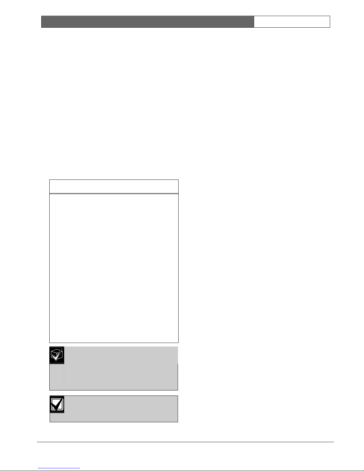
Figure 1: CP5 Eight Zone LED Codepad
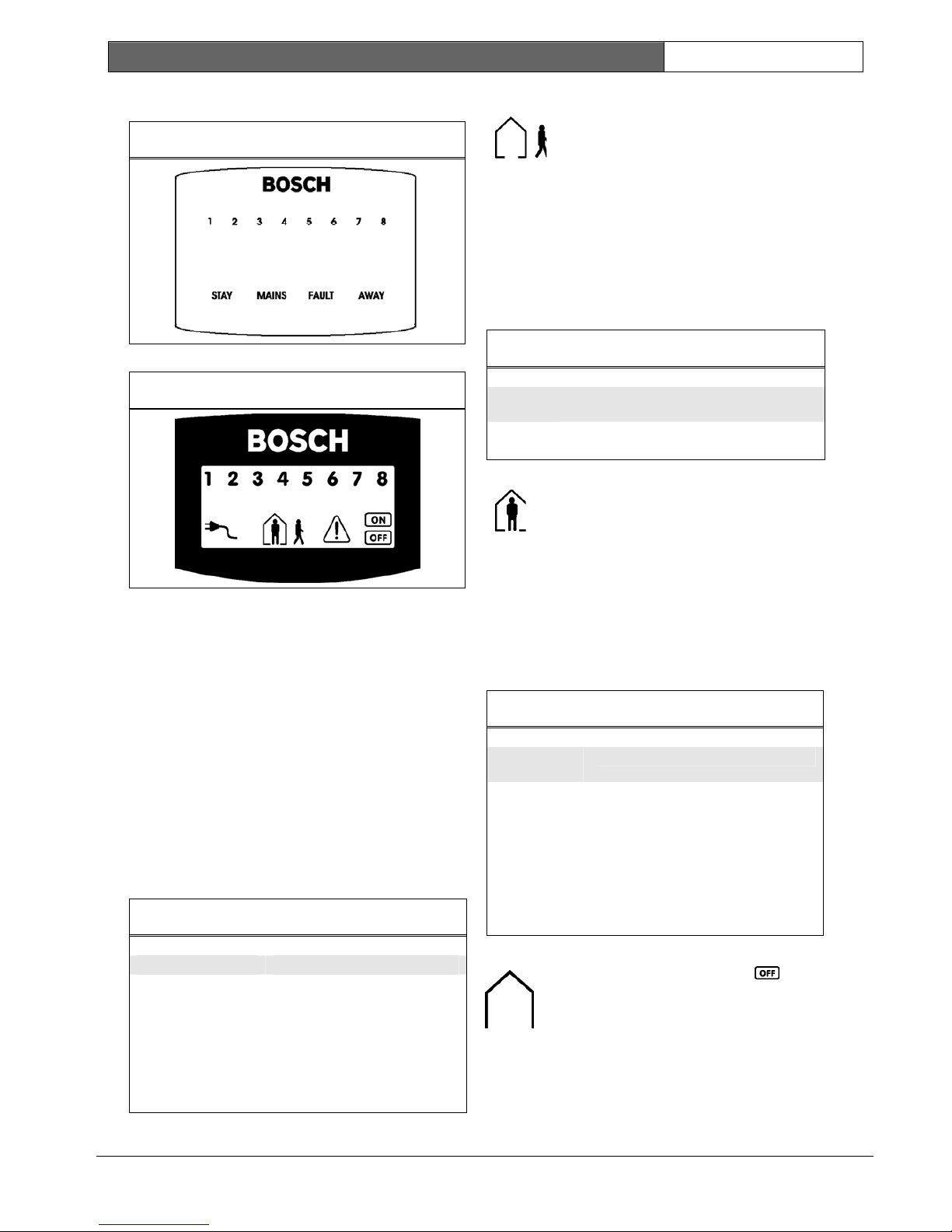
Figure 2: CP5 Eight Zone LCD Codepad
The codepad is the communications interface
between you and your alarm system. Use the
codepad to issue commands. The codepad offers
both visual and audible indications that guide you
through the general operation.
The codepad incorporates numerous indicators.
There are zone indicators that show the condition of
each zone and four other indicators for general
status. The following pages outline a list of situations
and the relevant indicators that are seen.
4.1 Zone Indicators
1 2 3 ….
The zone indicators (1 to 8) display
the status of the zones. Table 2 lists the
various situations that the indicators
display (such as, Zone Sealed/Zone
Unsealed).
Table 2: Zone Indicator
Zone Indicator Definition
On Zone is unsealed.
Off Zone is sealed.
Flashing Fast
(0.25 seconds on/
0.25 seconds off)
Zone is in alarm condition.
Flashing Slow
(1 second on/
1 second off)
Zone is manually isolated or
selected to be isolated.
4.2 AWAY Indicator
The AWAY indicator displays the
system is armed in AWAY Mode. The
AWAY indicator also flashes in unison
with the STAY indicator when
programming various options
throughout the Operators Guide.
See Section 5.1 Arming in AWAY Mode
for information on the different
methods of arming the system in
AWAY Mode.
Table 3: AWAY Indicator
AWAY
Indicator
Definition
On System is armed in AWAY Mode.
Off System is not armed in AWAY Mode.
4.3 STAY Indicator
The STAY indicator displays the system
is armed in STAY Mode 1 or STAY
Mode 2. The STAY indicator also flashes
in unison with the AWAY indicator
when programming various options
throughout the Operators Guide.
See Section 5.2 Arming in STAY Mode 1 for
different methods of arming in STAY
Mode 1. See Section 5.3 Arming in STAY
Mode 2 to arm in STAY Mode 2.
Table 4: STAY Indicator
STAY
Indicator
Definition
On System is armed in STAY Mode 1 or
STAY Mode 2.
Off System is not armed in STAY Mode 1
or STAY Mode 2.
Flashing twice
a second
Zone Isolating Mode or setting STAY
Mode 2 zones.
Flashing once
every 3
seconds
Day alarm status – day alarm turned
on.
4.4 System Disarmed
This indicator displays with the
indicator when the system is disarmed.
CC408 | Operators Guide | 5. Arming the System EN | 7
Bosch Security Systems | 5/04 | 920050O.OG.112
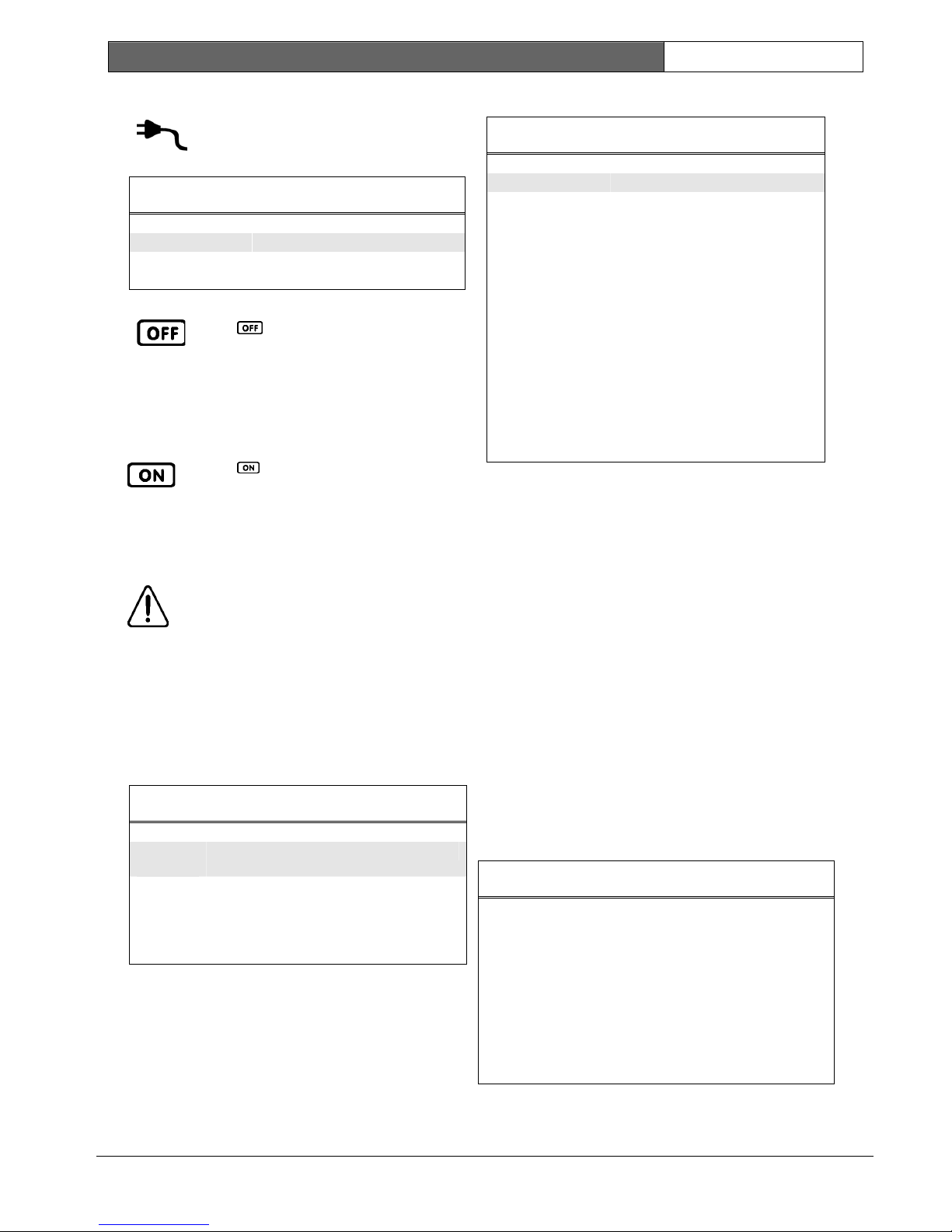
4.5 MAINS Indicator
The MAINS indicator displays the
systems AC mains supply is normal or
failed.
Table 5: MAINS Indicator
MAINS Indicator Definition
On AC mains power normal.
Flashing AC mains supply failed.
4.6 Off Indicator/Zone Sealed
The
indicator displays when the
system is in the disarmed state and
flashes when a zone becomes unsealed
during the disarmed state. The
indicator stops flashing when all zones
are sealed.
4.7 On Indicator/Zone In Alarm
The
indicator displays when the
system is armed in AWAY Mode and
flashes when an alarm occurs. The
indicator resets once a valid user code
is entered.
4.8 FAULT Indicator
The FAULT indicator displays the
system detected a system fault. See
Section 12. Fault Analysis Mode for
additional information on system faults.
Every time a new system fault is
detected (such as, FAULT indicator
flashing), the codepad beeps once
every minute. Pressing the [#] button
once cancels the once a minute beep
and acknowledges the fault (such as,
FAULT indicator on steady).
Table 6: FAULT Indicator
FAULT
Indicator
Definition
On There is a system fault that must be
rectified.
Off The system is normal, there are no faults.
Flashing There is a system fault that must be
acknowledged.
4.9 Audible Indications
Table 7 defines the audible indicators
generated by the codepad buzzer.
Table 7: Audible Indicators
Audible Indicator Definition
One short beep A button was pressed on the
codepad, or end of exit time when
armed in STAY Mode 1 or STAY
Mode 2.
Two short beeps The system accepted your code.
Three short beeps The requested function was
executed.
One long beep Indicates the end of exit time when
armed in AWAY Mode, or the
requested operation was denied or
aborted.
One beep every
second
Walk Test Mode is currently active
or warning before automatic arming
takes place.
One short beep
every minute
There is a system fault waiting to
be acknowledged.
5. Arming the System
There are several ways to arm the system depending
on whether you are:
• Leaving the premises and require all active zones
to be in a ready state for an intruder.
• Remaining in the premises and only require part
of the system to be in a ready state for an
intruder.
If a zone is not sealed at the end of exit time, the
zone is automatically isolated and constantly displays
on the remote codepad. The zone becomes an active
part of the system when the zone reseals. For
example, if a window is left open after exit time
expires, the window is not an active part of the
system until the window is closed. Opening the
window after exit time expired causes an alarm
condition.
Table 8 defines the different methods for arming the
system.
Table 8: Arming Methods
AWAY Mode
Arms the entire system. See Section 5.1
Arming in AWAY Mode.
STAY Mode 1
Arms all zones except those programmed
to be automatically isolated by the
installer. See Section 5.2 Arming in
STAY Mode 1.
STAY Mode 2
Arms all zones except those programmed
to be automatically isolated by the Master
Code holder. See Section 5.3 Arming in
STAY Mode 2.
CC408 | Operators Guide | 5. Arming the System EN | 8
Bosch Security Systems | 5/04 | 920050O.OG.112
Forced Arming
The feature of arming the system when a zone is not
sealed is known as forced arming. If the system does
not arm and a long beep is heard, forced arming is
not permitted. If this is the case, ensure that all zones
are sealed or manually isolated before arming the
system.
5.1 Arming in AWAY Mode
When you leave your premises and require all zones
to be in a ready state to detect intrusion, you arm the
system in AWAY Mode. When returning to your
premises, disarm your system (see Section 6. Disarming
the System) so you do not sound a false alarm.
There are two different methods for arming the
system in AWAY Mode. Method one is standard and
always operates. Method two is optional and may be
disabled by your installer if you do not want to use
single button arming.
Arming in AWAY Mode, Method 1
Enter your user code followed by the [#] key (for
example, [2 5 8 0 #]). Two beeps sound and the
AWAY indicator displays. Exit time starts counting.
Arming in AWAY Mode, Method 2
Hold down the [#] key until two beeps sound.
The AWAY indicator displays and exit time starts
counting.
5.2 Arming in STAY Mode 1
STAY Mode 1 is only used when the perimeter and
unused areas of the premises must be armed to
detect if an intruder is entering the premises. At the
same time it allows you to move freely within an area
that is automatically isolated.
Only your security company can program
zones automatically isolated in STAY
Mode 1.
There are two different methods for arming the
system in STAY Mode 1. Method one is standard
and always operates. Method two is optional and
may be disabled by your installer if you do not want
to use single button arming.
Entry Guard Timer for STAY Mode 1
When arming the system in STAY Mode 1, an
optional entry timer called Entry Guard Timer For
STAY Mode 1 is available. Use this entry timer to
delay the sirens if a zone is not automatically isolated
and triggers an alarm condition. Entry Guard Timer
For STAY Mode 1 is the delay time used for all
zones except 24-hour zones when the system is
armed in STAY Mode 1 or STAY Mode 2.
If the Entry Guard Timer For STAY Mode 1 is
programmed and a zone not automatically isolated is
triggered, the codepad beeps twice per second until
the entry timer expires or the system disarms. If the
alarm condition is not reset by entering your user
code followed by the [#] key (for example,
[2 5 8 0 #]) before the entry timer expires, the sirens
activate into alarm. Only your installer can program
this feature.
Arming in STAY Mode 1, Method 1
Enter your user code followed by the [*] key (for
example, [2 5 8 0 *]). Two beeps sound and the
STAY indicator displays. Exit time starts counting.
Any zones programmed to be automatically isolated
in STAY Mode 1 flash until exit time expires. At the
end of exit time, all zones selected to be
automatically isolated turn off and the codepad gives
one short beep.
Arming in STAY Mode 1, Method 2
Hold down the [*] button until two beeps are heard.
The STAY indicator displays and exit time starts
counting.
Any zones programmed to be automatically isolated
in STAY Mode 1 flash until exit time expires. At the
end of exit time, the zone indicators turn off and the
codepad emits one short beep.
5.3 Arming in STAY Mode 2
STAY Mode 2 is only used when the perimeter and
unused areas of the premises must be armed to
detect an intruder from entering the premises while
you move freely within an area that is automatically
isolated. Any Master Code user can program zones
to be automatically isolated in STAY Mode 2.
Entry Guard Timer For STAY Mode 2
When arming the system in STAY Mode 2, an
optional entry timer called Entry Guard Timer For
STAY Mode 2 is available. Use this entry timer to
delay the sirens if a zone is not automatically isolated
and triggered into alarm condition. Entry Guard
Timer for STAY Mode 2 is the delay time used for
all zones except 24-hour zones when the system is
armed in STAY Mode 1 or STAY Mode 2.
If the Entry Guard Timer For STAY Mode 2 is
programmed and a zone not automatically isolated
triggers, the codepad beeps twice a second until the
entry timer expires or the system disarms. If the
alarm condition is not reset by entering your user
code followed by the [#] button (for example,
[2 5 8 0 #]) before the entry timer expires, the sirens
activate into alarm. Only your installer can program
this option.

CC408 | Operators Guide | 6. Disarming the System EN | 9
Bosch Security Systems | 5/04 | 920050O.OG.112
Arming in STAY Mode 2
Hold down the [0] button until two beeps sound.
The STAY indicator lights and exit time starts
counting.
Any zones programmed to be automatically isolated
in STAY Mode 2 flash until exit time expires. At the
end of exit time, all zones selected to be
automatically isolated extinguish and the codepad
provides one short beep.
5.4 Programming STAY Mode 2 Zones
You can only program zones to be automatically
isolated in STAY Mode 2 if you have a Master Code.
How to Program STAY Mode 2 Zones
1. Enter your four-character Master Code, followed
by the [4] and [#] keys (for example,
[2 5 8 0 4 #]). Three beeps sound and the STAY
indicator flashes.
2. Enter the zone number to be automatically
isolated, followed by the [*] key (for example,
[1 *] = Zone 1, [2 *] = Zone 2).
The selected zone flashes. If you make a mistake,
enter the same zone number followed by the [#]
key to clear the incorrect zone.
To select additional zones to be automatically
isolated in STAY Mode 2, repeat Step 2 as many
times as required.
3. To exit this mode, press the [#] key when you
have selected all zones to be automatically
isolated in STAY Mode 2. Two beeps sound and
the STAY and AWAY indicators turn dark.
6. Disarming the System
When you enter the premises after the system is
armed in AWAY Mode, or if you have armed the
system in STAY Mode 1 or STAY Mode 2, you must
disarm the system before entry time expires to
disable detection devices that activate an alarm. Only
your installer can program the entry time.
If there was an alarm condition prior to disarming
the system, a flashing zone indicator displays
indicating a previous alarm on that zone.
How to Disarm the System
Enter your user code followed by the [#] key (for
example, [2 5 8 0 #]). Two beeps sound.
7. User Codes
7.1 Adding User Codes
Only the Master Code holder can add or change
other system user codes, including the Master Code.
Up to eight user codes can be programmed to
operate the system.
How to Add a User Code
1. Enter your four-character Master Code, followed
by [1] and [#] (for example, [2 5 8 0 1 #]).
Three beeps sound and the STAY and AWAY
indicators flash.
2. Enter the user code number (1 to 8) followed by
the [#] key (for example, [2 #] = User 2, [8 #] =
User 8). Two beeps sound and the selected user
number displays on the codepad indicators.
3. Enter the digits required for the new code
followed by the [#] key (for example, for user
code 5768, enter [5 7 6 8 #]). Two beeps sound
and the STAY and AWAY indicators turn dark.
To add or change other user codes, repeat this
procedure as many times as required.
7.2 Adding Radio Remote User Codes
Only the Master Code holder can add or change
other system user codes, including the Master Code.
Up to eight radio user codes (User Codes 9 to 16)
can be programmed to operate the system.
How to Add a Radio Remote User Code
1. Enter your four-character Master Code, followed
by the [1] and [#] keys (for example,
[2 5 8 0 1 #]).
Three beeps sound and the STAY and AWAY
indicators flash.
2. Enter the radio remote user code number (9 to
16), followed by the [#] key (for example, [9 #] =
User 9, [1 6 #] = User 16). Two beeps sound and
the selected user number displays on the
codepad indicators.
3. Press any button on the keyfob so the system
learns the ID number. Two beeps sound and the
STAY and AWAY indicators extinguish.
To add or change other radio remote user codes,
repeat this procedure as many times as required.
7.3 Deleting User Codes/Radio User
Codes
Only the Master Code holder can delete other
system user codes.
How to Delete a User Code
1. Enter your four-character Master Code, followed
by the [1] and [#] keys (for example,
[2 5 8 0 1 #]).
Three beeps sound and the STAY and AWAY
indicators flash.
2. Enter the user code number (User Code 1 to 8,
Radio User Code 9 to 16), followed by the [#]
key (for example, [2 #] = User 2, [1 6 #] = User
16). Two beeps sound and the selected user
number displays on the codepad indicators.
3. Press the [*] key to delete the selected user code.
Two beeps sound and the STAY and AWAY
indicators turn dark. To delete other user codes,
repeat this procedure as many times as required.
 Loading...